1. Introduction
Walking is not only one of the most fundamental activities that enables a person to be an active member of our society, but it is also the key to maintain the health condition [
1]. For people who have completely lost their walking ability due to spinal cord injury, therefore, it is mandatory to stand up and perform walking motions frequently with the help of assistive devices (e.g., a harness system, a robotic rehabilitation treatment system, etc. [
2]) to maintain the health condition. In this aspect, powered exoskeletons provide the complete paraplegic with the possibility to walk on the real ground, which is meaningful for rehabilitation of complete paraplegics, as well as their mobility.
Powered exoskeletons have been developed by many researchers in recent years, and several robots have been commercialized [
3]. Among many applications of the wearable robots, ones for assisting people with complete paraplegia may be the most advanced. Wheelchairs can improve the mobility of patients with complete paralyses, but they cannot provide standing postures and bipedal walking, which are important for healthcare. Many studies have shown that bipedal walking training can increase life satisfaction [
1,
2,
4,
5]. ReWalk, a commercial robot by ReWalk Robotics [
6], is being distributed to rehabilitation hospitals around the world. In addition, Ekso [
7] from Ekso Bionics, Indego [
8] from Parker Hannifin corporation and Rex [
9] from Rex Bionics are commercially available robots for disabled and paralyzed people. Many other robotic exoskeletons are being developed and commercialized [
10,
11].
The mechanism and control of powered exoskeletons have been studied mainly in terms of efficient force transmission generating a natural gait pattern. Through intensive studies, this has reached the completion stage to some extent. For more improved usability of powered exoskeletons for people with complete paralyses, it is important to accomplish not only the transmission of the actuation force, but also the immediate recognition of the user intention. At the same time, the user must be informed immediately if any event (e.g., mode change, fault detection, battery discharge, etc.) occurs in the robot system. Therefore, it is mandatory to design a user-friendly, comfortable, convenient, yet reliable user-interface (UI).
Various intention detection methods have been studied. One of the promising methods is to measure the physical contact force, such as a ground reaction force (GRF), measuring the reaction force between the ground and the user’s foot [
12,
13]. The GRF can be a real-time indicator of whether or not the feet are on the ground, but the intention cannot be detected in advance. In general, when the GRF is measured below a certain threshold value, the foot leaves the ground and is detected as a swing phase. However, for the case of complete paraplegics, it is impossible to generate the swing phase due to the complete loss of motor function of the lower limb. Human motion intent can also be detected using biomedical signals such as electromyography (EMG) of the leg muscles [
14,
15,
16,
17,
18,
19]. The EMG method is not suitable for patients who have completely lost their motor and sensor functions because they cannot sense the actual motion or contraction of the muscles.
The intention of movement is transferred by electrical signals induced by the brain’s neurons, and a control method using a brain-machine interface (BMI) has recently been widely studied. An invasive BMI method has been used in monkeys in many studies to measure and analyze the brain signals of body movements [
20,
21]. However, the invasive BMI methods are too risky and cannot be applied to daily-life applications [
10,
22]. As a non-invasive BMI application, scalp electroencephalographic (EEG) has been utilized also [
10]. For example, many applications used the EEG-based BMI to detect intention and control the assistive devices, such as orthotic devices and wheelchairs [
11,
23,
24,
25]. Donati et al. applied the EEG-based BMI to their exoskeleton robot and a gait training platform to confirm the effectiveness of the long-term training [
26]. Although the BMI intention recognition method is being studied intensively, it is not yet reliable and suitable for powered exoskeletons, which require
detection reliability. Malfunctions of the exoskeleton robot due to incorrect detection may add a significant risk to user safety [
10]. Therefore, these methods are not yet suitable for the UI of a robot for complete paraplegics for mobile use; a new UI system that makes the user reliably interact with the robot with minimal distraction is necessary.
In this paper, a new UI of the WalkON Suit, a powered exoskeleton for complete paraplegics, developed by Angel Robotics Co. Ltd. (formerly SG Robotics Co. Ltd., Singapore), is introduced. The new UI consists of see-through display (STD) glasses, as well as an OLED display and two tact switches installed on the handle of a crutch. The STD glasses are usually utilized for augmented-reality applications [
27,
28], but are utilized as a head-up display to transfer necessary information from the robot to the user in this paper. The wearer of the WalkON Suit can check the overall operation state, such as the foot displacement, the trunk inclination, the current gait mode, the elapsed time and the total step counts through the STD glasses, as well as through the OLED display of the crutch. The proposed UI system improves the usability of the WalkON Suit, such that the wearer’s field of view is widened and the training period with the robot is shortened, resulting in improvement of the overall safety and walking speed.
The WalkON Suit with the proposed UI system was utilized for a complete paraplegic to carry the torch of the Pyeongchang Paralympics 2018, as shown in
Figure 1. In addition to the new UI, the WalkON Suit revealed through the Pyeongchang Paralympics was different from the previous version introduced at the Cybathlon 2016 [
29] in many aspects. In particular, the design of the WalkON Suit has been improved aesthetically while fulfilling the role of a torch bearer. In this paper, the proposed UI system of the WalkON Suit and its verification by a human subject are introduced.
This paper is organized as follows.
Section 2 introduces the mechanical and electrical configuration of the WalkON Suit briefly.
Section 3 explains the motivation and the realization method of the proposed UI system. The experimental results are provided and discussed in
Section 4.
Section 5 concludes this paper and proposes future works.
2. Configuration of the WalkON Suit
The WalkON Suit has various unique features. For example, it utilizes a bi-articular actuation mechanism, which actuates both the hip and knee joints simultaneously. The bi-articular mechanism improves the overall energy efficiency significantly [
30]. The brace of the WalkON Suit is manually fabricated by medical orthotists and customized for each user, which is to guarantee the best fitness between the human body and the robot.
The WalkON Suit was first introduced to the public through the Powered Exoskeleton Race of the Cybathlon 2016 [
29], where the pilot of the WalkON Suit, Mr. Byeongwook Kim, won the bronze medal. The control of the WalkON Suit, however, was not simple enough for a paralyzed user, because the user had to check the operation state continuously through a small LCD display, like the other powered exoskeletons.
An improved version of the WalkON Suit was introduced in the torch relay of the Pyeongchang Paralympics 2018. Both robots for Cybathlon and Pyeongchang Paralympics share the same actuation mechanism, basic UI system, crutches, and so on, as shown in
Figure 2. Four synchronized 100-W BLDC motors are utilized to actuate each joint in both systems. The hip joints are actuated directly by the motors, and the knee joints are bi-articularly actuated through a linkage mechanism [
29]. The bi-articular mechanism is effective for controlling the position of an end-effector (i.e., the foot of the robotic leg), because it is similar to the human musculoskeletal system. In addition, all the hip and knee joint motors are mounted in the backpack placed at the trunk; therefore, the knee joint motor does not impose any unnecessary burden unlike the conventional mono-articular mechanism [
31].
The Cybathlon version of the WalkON Suit introduced in 2016 used the CompactRIO of National Instruments as the primary control processor, while the second prototype introduced in this paper uses a customized printed circuit board and the system on module (SoM) manufactured by the same company. By this replacement, the weight of the processor has been reduced from 2250 g to 77 g.
In addition, the UI system of the WalkON Suit has been improved compared to that in 2016. The crutches of the WalkON Suit are specially designed as a primary user interface; a -inch OLED display and two tact switches are installed on the handle of the crutch. Moreover, the information mandatory for the paralyzed human to control the WalkON Suit is informed through see-through display (STD) glasses specially developed for the WalkON Suit. The details of the proposed UI are described in the following section.
3. Design of UI System for the WalkON Suit
A person with paralysis due to complete spinal cord injury often encounters the impairment of both sensory and motor functions of the lower limbs. Therefore, the sensors and the motion analysis system of the powered exoskeletons should be able to monitor the overall status of the human-robot system, and the status should be informed to the user immediately and continuously.
People without gait disorders can walk uncautiously without checking their foot displacement or the balancing state. As normal walking is a habitual task, a normal person can do other things such as talking or looking around while walking. In this sense, the UI for powered exoskeletons should not impose much distraction on the user while operating the robot. The UI system of the WalkON Suit is developed in this manner.
3.1. Posture Analysis with the Conventional UI
Since the sensory function, as well as the motor function, of complete paraplegics is impaired, they are not able to recognize their postures. Thus, they need to observe their leg movements frequently for maintaining balance. For example, they need to know which foot will move forward (i.e., swing forward) to make the appropriate trunk movement for balancing. This is still necessary even after being fully adapted to the powered exoskeleton.
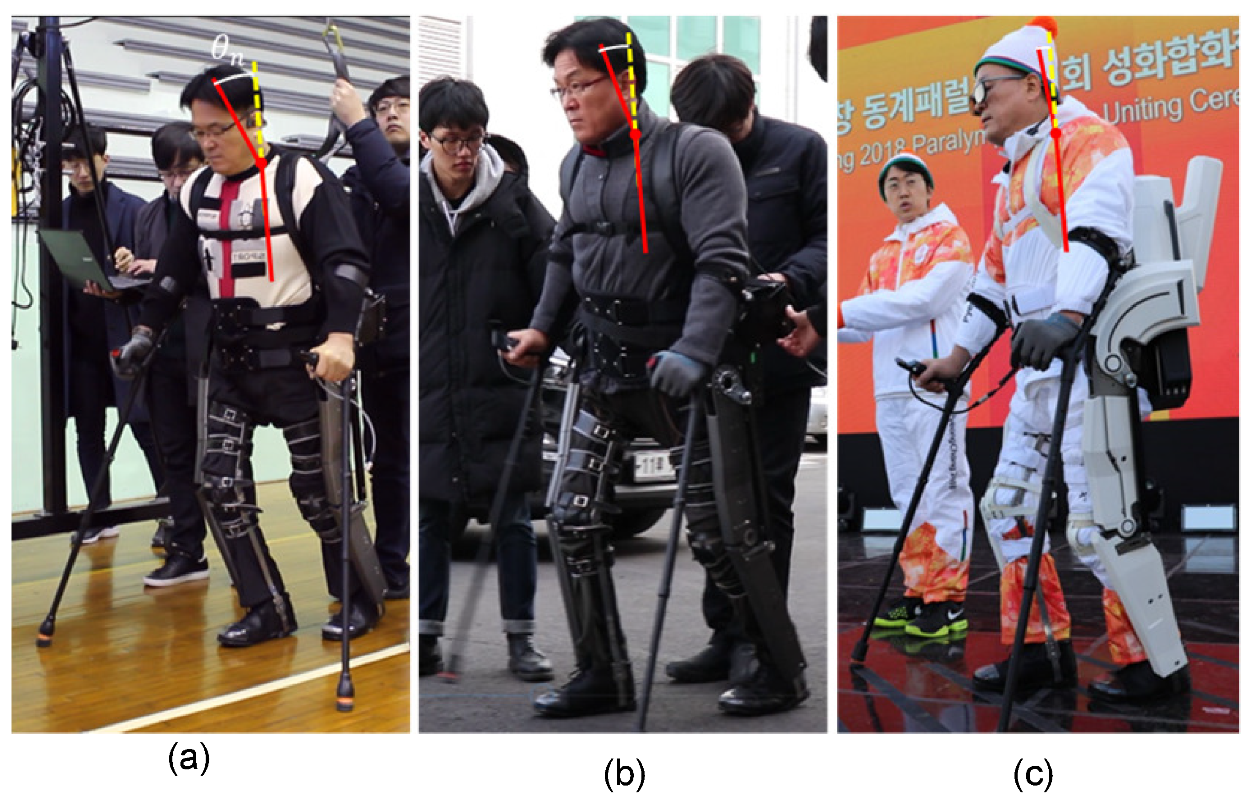
The posture to observe their lower limbs, however, is not easy for complete paraplegics wearing a powered exoskeleton. Since the flexion angle range of the neck is limited, they need to slightly lean forward to observe the leg movements, as shown in
Figure 3a. Moreover, they need to bend their neck even more excessively when staring at the screen to operate the robot, as shown in
Figure 3b, because the display is usually installed at the crutches or at the chest. It should be noted that leaning forward not only makes the overall posture unstable, but also imposes a large burden on the shoulder joints.
Figure 4 shows the schematic analysis of the posture of a person wearing the WalkON Suit. As the posture is quasi-static when staring at the screen, the forces acting on the crutches can be calculated by the static moment balance equation with respect to the foot (i.e., the point
B in
Figure 4):
or:
where
l is the distance between the foot and the shoulder joint,
and
are respectively the forces acting on the feet and the crutches,
and
are respectively the angles of the body inclination and the neck flexion and
and
are respectively the masses of the head and the overall body excluding the head, as shown in
Figure 4.
is a ratio to define the position of the center of mass of the whole body including the human and the robot. For the sake of simplicity, it was assumed that all the forces are in the vertical direction and the frontal plane posture is well-balanced. In addition, it was assumed that
l is the same as the distance from the shoulder joint to the tips of the crutches, which is a reasonable assumption in practice, because the length of the crutches is determined in this manner.
By a simple free body diagram analysis, it can be easily found that the force acting on the crutches, i.e.,
, has the same magnitude as the force acting on the shoulder joints. It should be noted in (
2) that
is increased as
and
increase. As the shoulder joints are vulnerable to repetitive large forces, the magnitude of
must be minimized, which requires minimizing
and
. This is, however, not simple in practice, because of the limitations in the UI, shown in
Figure 3.
3.2. Configuration of the Proposed UI System
Figure 5 shows the overall configuration of the proposed UI system for the WalkON Suit. The user transfers a command (i.e., the human intention to initiate or to terminate a leg motion) through two tact switches installed on the crutch (see
Figure 5a). Then, the user receives information necessary to operate the robot and to check the overall status through an OLED display installed on a crutch (see
Figure 5b) and see-through display (STD) glasses (see
Figure 5c). Both the displays show basically the same information, but the STD glasses show more details.
3.3. Interface for the Persons in the Vicinity
For safe operation, it is important to notify persons in the vicinity of a powered exoskeleton immediately when any risk or hazardous event is detected or expected. Like all the other powered exoskeletons, the WalkON Suit is not able to stand up from the ground by itself, and the user (i.e., a complete paraplegic) cannot restore the standing posture once having fallen down. Therefore, it is mandatory to prevent any hazard of falling down. To monitor the risks of falling down, the WalkON Suit has a risk monitoring algorithm [
29], which continuously checks the status of the battery and actuators, the trunk inclination, and so on. In order to notify the potential risk detected by the algorithm to the persons in the vicinity of the WalkON Suit, a multi-color LED and buzzer are utilized, as shown in
Figure 5d.
3.4. Input Interface for the User of the WalkON Suit
Since the advanced methods such as voice recognition or EEG analysis are not yet fully reliable, a physical interface such as tact button switches may still be the most intuitive and reliable means for an input interface. Complete paraplegics wearing powered exoskeletons should hold the crutches for stabilizing and maintaining the body balance. Therefore, the crutches of the WalkON Suit are designed not only to meet the ergonomic conditions, but also for the user to access and operate the tact switches easily while holding the crutches.
The number of tact switches to be installed on the crutch handle should be determined considering both the complexity of operation and the possibility of maloperation. (1) If the number of tact switches is less than that of the motion modes, which are the different leg motions that a powered exoskeleton can realize according to the user’s command, it is mandatory for the user to select the desired mode by pressing the button(s) appropriate times. This may cause an operation error due to the user’s mistake. (2) If the number of tact switches matches that of the motion modes, the operation strategy becomes simple. The powered exoskeleton introduced in [
32] used four tact switches to control four motion modes. In this case, however, too many buttons may be necessary, which increases the risk of maloperation.
Since the paraplegic user should hold the crutch handle tightly while operating the powered exoskeleton, the workspace of the thumb is the only area where tact switches can be placed. Therefore, the number of tact switches of the crutch handle of the WalkON Suit was selected as two; Button 1 and Button 2, as shown in
Figure 5. The main function of Button 1 is action or select, and that of Button 2 is the termination of the current mode. The action and select are distinguished by the duration of pressing Button 1, i.e., the user can initiate an action by pressing Button 1 for a short duration, and select any desired mode by pressing Button 1 for a longer duration.
The two tact switches are used to mange the following four motion modes.
3.4.1. Sit Mode
This is the motion mode to sit down. Sit mode can be selected after completing stand mode or align mode, as listed in
Table 1. When the user makes a command of action (i.e., pressing Button 1 for a short duration) in sit mode, the WalkON Suit starts bending both the hip and knee joints until sitting on the chair. If the user is already sitting, the robot does not take any action even if the action command is made.
Since the user may embark on the powered exoskeleton from a wheelchair, the algorithm of the WalkON Suit starts from sit mode.
3.4.2. Stand Mode
This is a motion mode to stand up. Stand mode can be selected after completing sit mode, as listed in
Table 1. When the user makes an action command in stand mode, the WalkON Suit starts extending both the hip and knee joints until standing straight. If the user is already standing, the robot does not take any action. After standing up, the user can start walking, sitting down or re-aligning his/her legs.
3.4.3. Walk Mode
This is a motion mode to move forward. Walk mode can be selected after completing stand mode or align mode, as listed in
Table 1. Walk mode consists of two motion phases, swing and stance, according to the ground contact condition. If the user makes an action command while the left foot is placed forward, then the left leg is controlled as the stance phase, and the right leg is controlled as the swing phase to place the right foot forward. Likewise, the right leg is in the stance phase, and the left leg is in the swing phase, when the user makes an action command while the right foot is placed forward.
If it is the first time making an action command in walk mode after completing stand mode or align mode, the right leg starts the swing phase first.
It should be noted that the user must make supplementary efforts to stabilize the overall posture while walking. As walk mode consists of two different actions (i.e., the stance and swing phases), the user must always check which foot is placed forward before making an action command.
3.4.4. Align Mode
This is a motion mode to re-align the legs. Align mode can be selected after completing stand mode or walk mode, as listed in
Table 1. When the user makes an action command in align mode, the WalkON Suit starts positioning the feet one by one such that both feet are placed at the same position. After completing align mode, the user should be standing straight.
Figure 6 shows the overall operation strategy of the WalkON Suit using the two tact switches. The selectable modes are expressed with different-colored lines in
Figure 7.
3.5. Output Interface 1 of the WalkON Suit: OLED Display
As the number of tact switches is less than the number of motion modes, it is mandatory for the user to select the desired mode by pressing the buttons appropriate times. For this purpose, a display is necessary, and thus, an OLED display is installed on the handle of a crutch to indicate the mode lists that the user can select, as shown in
Figure 5.
When the robot is turned on so that the program is in an initialization mode, the display shows the logo of the WalkON Suit, as in
Figure 8a.
Figure 8d shows an example of the mode list. In the example of
Figure 8, if the user makes a select command (i.e., Button 1 pressed for a long duration), sit mode is to be selected, and the display is changed as in
Figure 8e. Then, the robot is in sit mode, and it starts sitting down when the user makes an action command (i.e., pressing Button 1 for a short duration). In this procedure, the display shows
Figure 8f.
Figure 8b,c show the examples of stand mode and walk mode. In walk mode, the feet positions are also displayed, as shown in the figure, to help the user be aware of which foot will move forward.
3.6. Output Interface 2 of the WalkON Suit: Head-Up Display with See-Through Display Glasses
A head-up display (HUD) refers to any transparent display that provides necessary information without requiring users to look away from their usual viewpoints [
33,
34]. As the name of HUD describes, it is a UI system that allows a user to obtain information for operating machines with the head positioned up. It is also a great advantage of an HUD that the users do not have to repetitively change the eye focus between distant objects and near displays. HUDs have been proposed for many applications. For example, an HUD is being utilized for military purposes to overlay tactical information.
In this paper, an HUD is proposed for the user of the WalkON Suit to walk with the head positioned up, i.e., to minimize
and
in
Figure 4. This is very important, because the larger
and
, the more increased burden to the users’ arms, as in (
2). Excessive
and
may result in falling forward, which is fatal for a complete paraplegic wearing a robot. In order for the user to be able to walk with his/her head straight up, an HUD may be a good solution to provide the necessary information to operate the WalkON Suit without looking at the toe or the display of the crutch. However, unlike the HUDs in the other applications, such as vehicles and airplanes, the powered exoskeletons do not have a windshield in front of the user. Therefore, to realize the HUD system in the WalkON Suit, smart glasses that have a see-through display (STD) are utilized, as shown in
Figure 9. The transparent display of the smart glasses allows the user to view information while looking forward.
The STD glasses system receives the operation status of the WalkON Suit (e.g., the motion modes) via Bluetooth serial communication. In addition to the motion modes, the remaining battery level, the total number of steps and the system error status are displayed on the STD glasses. As the WalkON Suit must operate safely even if the Bluetooth connection is lost, the data are transmitted only from the robot to the glasses.
The STD glasses include a transparent screen, which shows a progress indicator, the foot positions, a warning indicator and an analysis result after completion of walking. The transparent screen of STD glasses shows an image overlapped with the environment. In the display that the user sees, a donut chart shows how long the user has walked with respect to the maximum step counts, which is preset (see
Figure 9a). On the center of the donut chart, the number of steps and the current motion mode are displayed; e.g., walk mode is shown in
Figure 9c. The foot positions are also shown, as in
Figure 9d, which allows the user looking forward while walking. In addition to the necessary information related to motion modes, the STD glasses also show warning messages if any potential hazard is detected, as in
Figure 9e. When the operation is terminated, the total operation time and the total number of steps are displayed as in
Figure 9f.
5. Discussion and Conclusions
In this paper, a new user interface for a powered exoskeleton, the WalkON Suit, for complete paraplegics was introduced. The WalkON Suit is a robot developed for complete paraplegics and aimed at allowing the wearer to walk freely in the outdoors and had showed its possibilities through events such as Cybathlon 2016 and the Pyeongchang Paralympics Games 2018. Therefore, the WalkON Suit is not a rehabilitation device for short-term or long-term treatment effects in medical use, but rather a device that allows people to do their daily activities. With the proposed powered exoskeleton, a complete paralysis patient will be able to improve his/her quality of life by obtaining a feeling of walking, gaining confidence and participating in social activities. As a person with complete spinal cord injury can neither move, nor sense the lower limb, it was mandatory for the users of the previous version of the WalkON Suit [
29] to observe their leg movements continuously. Moreover, the conventional UI utilized a small display installed on the crutch or on the chest, which required looking down when operating the powered exoskeletons. For these reasons, the user of a powered exoskeleton had to look down frequently, which caused gait instability, reduced walking speed and shoulder and neck pain. Therefore, in this paper, a new user-interface (UI) of a powered exoskeleton for complete paraplegics was introduced. The proposed UI system consisted of two tact switches and a display installed on the crutch and a head-up display based on glasses with a see-through display (STD).
Different technologies may also be available for detecting the gait intentions of people, such as EMG and foot pressure patterns, which are more suitable for people with partial impairment in walking ability, The foot contact status may be indicated by a visual, tactile or auditory interface, as important information indicating that the wearer of the robot is ready to begin the next step. Donati et al introduced a long-term gait training protocol using a combination of virtual reality training, visual-tactile feedback training, powered exoskeleton training and robotic body weight support (BWS) gait training on a treadmill [
26]. However, the effects of single training in tactile feedback, virtual-reality training or exoskeleton training, respectively, have not been clearly verified yet. Many studies have shown that it is possible to use a brain-machine-interface (BMI) for control of robotic exoskeletons [
35,
36,
37,
38].
Although the methods listed above provided powered exoskeletons with the possibility to interact with humans in a more sophisticated way, they are not yet reliable for complete paraplegics in practice. According to the authors’ experience, the best user interface for each paraplegic user may be highly dependent on the personal preference of the individual. For example, complete paraplegics who have completely lost their proprioception, like the human subject who participated in this research, are very sensitive to the reliability of the robot system. When a robot does not recognize a command (i.e., the motion intention) on occasion, they become very nervous. This may be a general case for people with complete paraplegia, as their body is vulnerable and their curability with respect to any further injury is very poor. Therefore, the most important requirement for the powered exoskeletons of complete paraplegics is reliability. This is the reason why the proposed system was developed based on buttons and an HUD to reduce their physical burden to check their leg positions visually frequently, while maintaining a high operation reliability. Complete paraplegics with the ASIA level of A or B, in particular those with complete loss of sensory functions, neither generate any EMG signal nor feel the damaged body parts. Therefore, it is clear that the EMG is not a proper solution for the user-interface for such users. A haptic device may be a good solution to deliver the interaction forces with an environment (e.g., the ground reaction force) to the body part that is not damaged (e.g., the trunk) by bypassing the cut spinal nervous system. For example, the human subject who participated in this research has a spinal injury at the level of T-10, which means he does not have any feeling below his navel. For this case, it is impossible to transfer all the necessary tactile information through the haptic system. Nevertheless, the authors fully admit that a haptic device is a good solution for people with incomplete paraplegia and with a low paraplegia level. In particular, for those with loss of sensory function only below the knee joints, the haptic device would be a perfect solution for regaining the gait stability. This will definitely be the future work of this paper.
In this paper, a combination of buttons and an HUD was applied as a user interface for a complete paraplegic user wearing a powered exoskeleton. The proposed method was developed for the sake of 100% reliability while providing the minimal necessary information for realizing a stable gait. The finite state machine for operating the robot with buttons was optimized to minimize the number of clicks to minimize any potential malfunction by selecting an undesired motion mode. The proposed UI system was applied to the WalkON Suit, a powered exoskeleton for complete paraplegics. As the STD glasses provided the necessary information for operating a powered exoskeleton, such as a progress indicator, the foot positions, a warning indicator, etc., the user of the WalkON Suit did not have to look down continuously to check the leg movements and to watch the display on the crutch. Consequently, the proposed UI system resulted in a critical improvement in the gait stability, the gait speed, as well as the user experience. The WalkON Suit with the proposed UI was utilized for the torch relay of the 2018 Pyeongchang Paralympics. A complete paraplegic successfully walked about 20 m carrying a torch and delivered it to the next torch bearer.
The proposed UI method was verified by only one subject in this paper. For the proof of the generality of the effectiveness of the proposed method, a statistical study with enough human subjects may be necessary. A practical problem was that the powered exoskeleton used in the experiment, called the WalkON Suit, was custom-fitted, which means that the robot could be worn only by the human subject who participated in this paperwork. Nevertheless, we believe that the improvement in the gait speed and the neck posture was scientifically meaningful even though it was a result verified by only a single subject. We assumed that the limited gait speed and the poor gait stability were due to the problem of complete paraplegics needing to check their leg positions visually frequently, and we proposed an engineering solution to solve this problem by adopting the see-through display technology. The experimental result showed that the proposed hypothesis was correct from the engineering viewpoint. A new version of the WalkON Suit, which can be worn by multiple users, is being developed by Angel Robotics. Once the new version of the WalkON Suit is ready, a statistical study of the user interface will be carried out, which is the future work of this paper.
The application of a whole-body control method to a powered exoskeleton to enable walking without holding crutches may also be a possible topic in the future work. Currently, there is no exoskeleton available on the market that supports self-balancing [
2,
39]. Therefore, powered exoskeletons for over-ground walking of people with complete paraplegics need supplementary equipment such as a cane, forearm crutches or a wheeled walker [
2]. Future research on how to safely fall down and get up again while wearing robots will also be conducted. This can be more realistic and practical than developing robust exoskeletons that do not collapse.


