Article

Smart Grid Testing Management Platform (SGTMP) †

1
Faculty of Science, University of Amsterdam, Spui 21, 1012 WX Amsterdam, The Netherlands
2
Faculty of Informatics, Masaryk University, 602 00 Brno, Czech Republic
*
Author to whom correspondence should be addressed.
The research was supported from ERDF/ESF “CyberSecurity, CyberCrime and Critical Information Infrastructures Center of Excellence” (No. CZ.02.1.01/0.0/0.0/16_019/0000822).
Appl. Sci. 2018, 8(11), 2278; https://doi.org/10.3390/app8112278
Submission received: 12 October 2018 / Revised: 2 November 2018 / Accepted: 14 November 2018 / Published: 18 November 2018
(This article belongs to the Special Issue Smart Grid and Information Technology)

Abstract

:
The Smart Grid (SG) is nowadays an essential part of modern society, providing two-way energy flow and smart services between providers and customers. The main drawback is the SG complexity, with an SG composed of multiple layers, with devices and components that have to communicate, integrate, and cooperate as a unified system. Such complexity brings challenges for ensuring proper reliability, resilience, availability, integration, and security of the overall infrastructure. In this paper, we introduce a new smart grid testing management platform (herein called SGTMP) for executing real-time hardware-in-the-loop SG tests and experiments that can simplify the testing process in the context of interconnected SG devices. We discuss the context of usage, the system architecture, the interactive web-based interface, the provided API, and the integration with co-simulations frameworks to provide virtualized environments for testing. Furthermore, we present one main scenario about the stress-testing of SG devices that can showcase the applicability of the platform.

1. Introduction

Traditional power grids distributed and managed energy from a centralized system in one direction, from the energy provider to the customers [1]. With growing demands for reliability and efficiency of the grid operation, there has been a necessity to develop a more interactive, interconnected, and dynamic grid model [2]. As a result, smart grids (SGs) improve electricity management by involving advanced two-way communications and operational capabilities, which allow one to deliver electricity in a more efficient, reliable, sustainable, and safer way [3,4]. The SG technology regulates smart devices at consumers’ home and buildings with the aim to save energy and decrease costs [5].
Software testing plays a relevant and significant role in today’s society, to provide reliable and safer systems [6,7,8]. However, testing in the context of SGs is extremely complex due to the multi-layer structure of the overall infrastructure. Many layers need to coexist, each one responsible for different areas such as communication protocols, information exchange, and service provision [9]. Each of these layers has to be tested separately and as a whole system to ensure faultless and reliable energy supply [10]. Furthermore, the nature of SGs as a cyber-physical system involves integration with hardware devices, making use of modeling and simulations highly relevant to discovering integration issues at scale [11,12].
Many SG testing/simulation platforms have emerged over the years, focusing on simulating part of the complexity within SGs, both at the power and at the communication network level [13]: Smart GridLab [14], GridSim [15], Smart-Grid Common Open Research Emulator (SCORE) [16], Smart Grid Testbed [17], and GridLAB-D [18] are some of the main platforms available. In general terms, the main goal of such platforms is to provide researchers with instruments necessary to aid in a more reliable comparison of solution designs in the context of the SG infrastructure, be it communication-, hardware-, or software-related. All these platforms have the ultimate goal to provide a common testbed for SG implementation capabilities, with the main understanding that the complexity of SG modeling calls for so-called “co-simulations”: the evaluation of multiple independent simulations integrated using a software interface [13].
The goal of this paper is to present the implementation details, experiences, and open issues derived from the development of a platform, a smart grid testing management platform (herein referred to as SGTMP), that can support SG devices and hardware-in-the-loop testing and simulations. SGTMP supports test management, test execution, co-simulations of hardware-software components, test monitoring, and reporting. The platform is focused on closing the gap in current co-simulation research as discussed in Steinbrink et al. [19], regarding the provision of a configurable, GUI-supported environment to support cyber-physical systems testing and modeling. SGTMP is a Java-based web-application with a supporting REST API that can allow one to manage tests and run hardware/software simulations.
The article is structured as follows. In Section 2, we explain the SG concept and the requirements for an SG testing environment, together with the support of a testing process. The architecture and implementation of SGTMP are discussed in Section 3, with details about the integration of testing and co-simulations, supported by the Mosaik framework [20,21]. Section 4 proposes a deployment scenario to demonstrate a practical application of the platform for SG components stress testing. Section 5 includes the conclusions and future works.

2. Background

In this section, we cover background and motivation for the creation of SGTMP. We look first at the context of SG, and we then move to general testing concepts and important requirements for SG testing as well as the decision regarding which testing processes/co-simulations should be used within SGTMP.

2.1. Smart Grid (SG)

An SG builds upon a traditional power distribution grid, adding several layers to allow for smart two-way communication (power and information flows) to improve the quality of provided services [1]. At its core, communication between SG components is accomplished by connecting all of the components and sensors into a grid network [3]. An SG can be described through three main systems: a smart infrastructure system (energy, information, and communication infrastructure fundamental for the smart grid), a smart management system (providing advanced management and control services), and a smart protection system (providing advanced grid reliability analysis, failure protection, and security and privacy protection services) [3].
The complexity of the SG is well represented by the smart grid architecture model (SGAM) framework, defined by the CEN-CENELEC-ETSI standardization group [9]. SGAM suggests considering different levels to tackle the SG complexity: the component layer (physical and virtual devices), the communication layer (e.g., stacking the different protocols), the information layer (modeling of information), the function layer (provided functionality), and the business layer (business goals in terms of services provided). All these layers need to be considered for the provision of SG-related services.
The core component for monitoring and source of consumer data for predictions in an SG is a smart meter (SM). SMs are located at each power distribution endpoint (residential or industrial). They are responsible for monitoring the power consumption like traditional energy meters; in addition, they also send usage statistics back to the grid, which allows instant collection of energy consumption for a given region [4]. Together with other data from the grid, instant power production and a power consumption profile can be generated. Over time, a consumption model can be developed, which will serve as a way to predict power usage over time. The prediction can be used to intelligently change the power production of non-renewable energy power plants to meet the current and near-future energy demand, which will help to save resources and at the same time prevent potential blackouts [22]. With the help of SM deployments, the time required to detect these abnormalities is significantly reduced when compared to a traditional power distribution grid [4,23,24].
One of the main advantages of an SG is the self-healing capability. Therefore, in case of a failure of a power supplier or distributor, the grid can automatically re-route power across a different network or send an alert to other power generators to increase their power output [25]. In a traditional grid, this typically leads to blackouts for the entire distribution region. Another benefit of an SG is that individual power producers may decide to add electricity to the grid, mainly from renewable resources (e.g., photovoltaic panels and wind turbines) [25]. By allowing even small-scale producers to sell energy into the grid, the overall environmental impact of power production from non-renewable sources is reduced, granting better load balancing during times of peak power usage.

2.2. Smart Grid Testing Requirements

The complexity of the SG poses several challenges that are at the basis of the conception of the SGTMP software system. This section discusses the requirements for creating an SG testing environment from the software perspective. The software environment can take care of simulation orchestration and test result processing and can provide meaningful feedback from each test to the user.
The SG domain encompasses many areas as represented by the SGAM framework [9]. Each of these areas must be tested in isolation and as a whole system before deployment, when evaluating system changes or as a continuous testbed for the replication of errors reported from already deployed infrastructure. SGTMP is designed to adhere to the requirements described in this section to the full extent allowed by the underlying technologies. We summarize SG testing requirements from a series of survey papers (Kok et al. [26], Karnouskos and Holanda [27], Wang et al. [28], Hahn et al. [29]). A summary of the requirements described in this section is in Table 1.
As discussed in Kok et al. [26], at the core of each SG modeling goal, there are aspects of the power grid (electricity flow) and data flows between entities related to the power grid. Power flow can be either real or simulated. For non-simulated power flows, the energy is created by actual hardware (generators powered by turbines, photovoltaic panels, etc.), and this power is transmitted to other parts of the grid. Another possibility is to use simulated power flow, where all or some of the power flow is simulated in software. If all of the tested energy distribution devices are virtualized or it is possible to provide hardware devices with only the simulated readings, this alternative can provide more significant flexibility in simulated devices. If certain tested devices require power from the grid to function, it is possible to take a hybrid approach, in which the power flow is still simulated; however, the devices requiring power are attached to a generator, whose power output is controlled by the simulation environment.
From the information exchange side, an SG testing process must consider different device types: (i) devices exchanging data not attached directly to the power grid (Type), (ii) devices directly attached to the power grid not exchanging data (Type B; i.e., not “smart” devices), (iii) devices both connected to the power grid and exchanging data (Type C), and (iv) intruders (both physical and virtual, Type D) [26,29]. Each of these device types presents a different challenge for the testing platform. Type B devices are primarily power lines and transformers without any network reporting capabilities. They are primarily required for knowing about the entire SG topology and come into play in system-wide simulations, where all SG components must be tested. Type A devices are part of the SG and are thus sending data to other parts of the grid, receiving data from other parts of the grid or external systems. These devices do not have to be software only: they can be, for example, weather stations used for predicting the power output of photovoltaic panels. By sending commands to other components, they can influence the state of the SG. In the SG domain, these types of devices are primarily control systems (e.g., supervisory control and data acquisition (SCADA) control systems). Type C devices are a combination of Type A and Type B devices; therefore, the simulation environment must be capable of interacting and simulating parts of both the power grid and the information exchange network. Type D devices are mainly concerned with simulation and study of cyber-physical attacks on the SG. By being able to test cyber-physical attacks, it is possible to evaluate SG safety and identify potential attack vectors. Once an attack is taking place in a testing environment, it can be further used for automatic anomaly and intrusion detection on the network. Network analysis can be either real-time, or it can be run after the testing process has finished—if it requires a significant amount of processing. Additionally, the testing environment should support features such as controllable packet loss, congestion simulation, and variable network bandwidth.
The evaluation of SG testing is another important requirement [26,27]. Extensive interaction captures between all of the devices under test, and any outside interactions with the system need to be considered. No interactions should be done outside of the simulation/testing environment, since these interactions cannot be captured, reproduced, and analyzed, leading to unreproducible tests. In an ideal situation, if all of the data exchange and state data is captured, it should be possible to “play back” the entire testing process or observe the state of any device at a specific point in time. For long-running tests, this is a critical requirement, as it can be infeasible to re-run the tests to recreate the exact circumstances of the failure. These requirements lead to the next one: handling large amounts of data for processing and storage. If the state of the tests has to be recorded at each specific time, there must be a logging system in place to handle processing of all of this data and subsequent storage for future retrieval. For real-time systems, the logging system must also process data continuously for extended periods of time (days to months) without failure. Extensive logging can also aid in analyzing component or whole system crashes and aid in determining the root cause of a device failure (e.g., destruction and firmware inoperability) where the device is no longer operational and data cannot be retrieved directly. Another requirement is being able to view the testing state and state of the devices during the testing/simulation process to immediately know the state of all devices. This can be used to detect any possible faults early in the process, saving time.
An SG can be deployed to many locations and it can span several cities, regions, and countries. It is therefore essential to test an SG not only for one specific topology but for multiple possible topologies [27,28]. The topology of the SG to be deployed is not always known in advance during the evaluation phase. It can be desirable to know if the created SG model will generalize to multiple possible topologies. This result can be accomplished by generating various SG topologies, either automatically as in [28] or based on real-world data and requirements.
From the point of view of integrating different simulators, the testing platform must support several types of simulators made by several companies and with no guarantees of compatibility [27]. The simulators can be single unit systems, communicating through a defined interface (both software and hardware) or the simulator can be composed of several units, creating a multi-agent system (MAS) [30,31]. A single MAS can be reduced through abstraction to a single unit system, so the internals of the MAS can be considered a black box for the simulation. An alternative is to decompose the MAS into its components and connect them by the simulation framework. The advantage of this approach is that parts of the MAS can be virtualized/exchanged more efficiently while keeping other hardware parts for hardware-in-the-loop (HIL) testing. Each simulator can be purely hardware (e.g., power generator), software (e.g., weather station), or a combination of the two (e.g., smart meter).

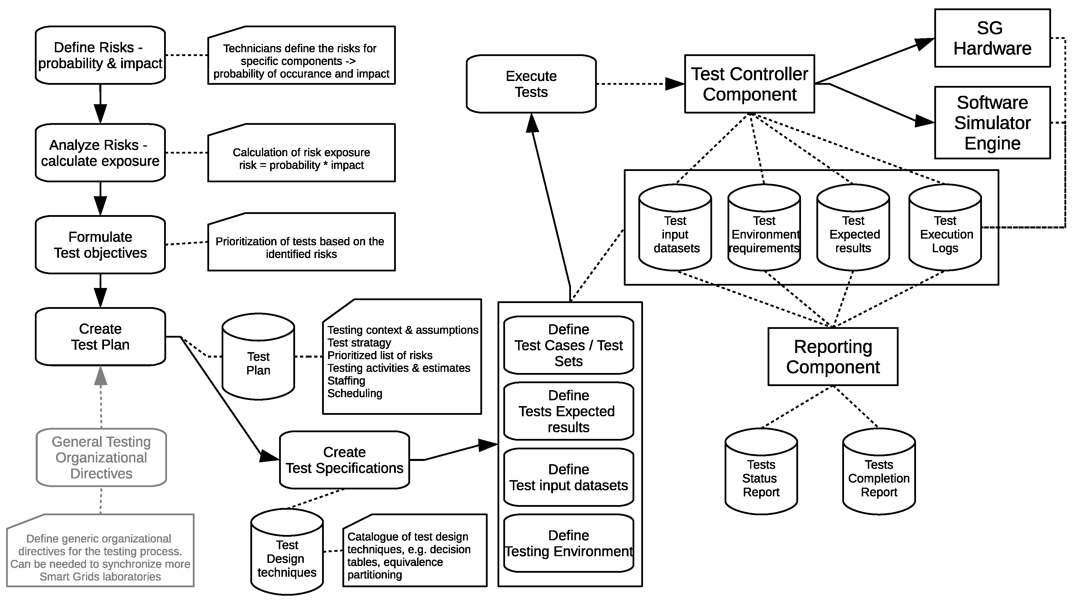
2.3. The ISO/IEC/IEEE 29119 Testing Process

Software testing standards/models provide a way to perform tests on a uniform and consistent basis [32]. Standards allow for test results to be repeatable and reproducible [33]. For the implementation and usage of SGTMP, we considered the underlying testing process that can be supported, as all the data models need to be adapted. Several benefits can be derived from the adoption of a testing standard/framework. From a general point of view, the main advantage is to define and follow processes and practices that have been applied in similar contexts and proven beneficial over time [32]. Another benefit is to ease the communication among all project stakeholders. This can refer to the standard to understand the documented steps in the process, allowing long-term process improvement.
There are many testing process models/standards which can be adopted within an organization, and a full discussion would be outside the scope of this work. More extensive discussions about characteristics of different testing standards can be found in works by Afzal et al. [32], Garcia et al. [34], and Garousi et al. [35,36], Swinkels [37], Farooq and Dumke [38], Farooq [39], Abdou et al. [40]. In this work, we considered the most reported models: Test Maturity Model integration (TMMi), Test Process Improvement (TPI), Critical Testing Process (CTP), Systematic Test and Evaluation Process (STEP), and ISO/IEC/IEEE 29119 [32,34]. To support SGTMP, we selected the ISO/IEC/IEEE 29119 standard, a standard created in 2013, expected to reach full adoption in upcoming years. The standard can be used for a wide variety of application domains and levels of criticality and is not specific to any particular life cycle, so it is applicable for testing on projects using sequential, iterative, and agile approaches [33]. Extensions to the standard and adaptations are expected to emerge over the years: it is as such expected that more adaptations of standards/frameworks/methodologies will emerge in the upcoming years, possibly based on ISO/IEC/IEEE 29119, making SGTMP easier to adapt.
The supported testing process is based on ISO/IEC/IEEE 29119 indications (Figure 1). The current implementation does not support all the steps, but SGTMP was created taking into account possible extensions. ISO/IEC/IEEE 29119 suggests that a risk-based approach is considered [41]: tests should be prioritized by the more risky components regarding impact and probability of occurrence. Test techniques are selected for each test, and test plans can be defined, containing necessary information about context, tests, the table of risks and their rating, test strategy, staffing, and scheduling. Test specifications are defined based on the design specification, case specification, procedure specification, data requirements, and environment requirements. It is important to note and store all conditions of a test run (such as particular external parameters). Once tests have been defined, they can be run by the platform by interfacing with the software and hardware devices. The test controller takes test specifications and requirements and runs the tests. When tests are executed, different reports and logs are automatically created. These are important to determine the test status results and cause of possible incidents (e.g., hardware failures).

2.4. SG Simulations and Co-Simulations

One relevant part of SGTMP is the support for SG simulations, as test cases can be too complex to be managed due to the vast amount of layers, components, scenarios, and device states. SGTMP can support co-simulations, defined as the coordinated execution of more simulation models with different representations and runtime environments [19,21]. Co-simulations can be seen as the composition of different simulators [42] and are a current trend in the SG domain, as recent research shows (e.g., Bian et al. [43], Li et al. [44]). As we will detail in the implementation part, SGTMP supports the Mosaik framework for co-simulations [20,21].

2.5. Related Works

To our knowledge, there are no existing platforms that can be directly compared to SGTMP. The one that is nearest in terms of implementation is the one in Annor-Asante and Pranggono [17], where a smart grid testbed with low-cost hardware and software is proposed based on the Arduino microcontroller, XBee radio modules (wireless data acquisition modules), a botnet simulator, and intrusion detection systems. The aim of the platform is to aid in research and education, similar to our previous work [22]. However, the focus of the platform in Annor-Asante and Pranggono [17] is more on cybersecurity and not on the provision of a general management platform for testing and simulations, as is SGTMP.
Other comparable platforms are SmartGridLab [14], GridSim [15], Smart-Grid Common Open Research Emulator (SCORE) [16], and GridLAB-D [18], although these platforms are more focused on the simulation of communication networks within SGs, compared to SGTMP [45]. SmartGridLab [14] proposes a wireless network to emulate a network composed of smart meters, power switches, suppliers, and appliances. Such a testbed can be used for different scenarios, such as demand-response energy pricing changes. GridSim [15] allows simulating power grid operation, control, and communications at the scale required for meaningful SG scenarios. It comprehends power systems simulations, communication, and control center applications. SCORE [16] is an emulator platform for both SG power and communication networks. The communication module supports several wireless communication models and protocols, while the power module can emulate power flows and energy models. SCORE can be used to evaluate several SG scenarios (e.g., real-time demand-response pricing changes). GridLAB-D [18] presents a power system modeling and simulation environment, allowing integration with third-party data management and analysis tools. Compared to SGTMP, GridLAB-D is more focused on the algorithmic part of simulations, allowing one to model and simulate various aspects of SGs (e.g., peak load management).

3. Implementing SGTMP

Based on the requirements discussed in Section 2.2 and the testing process described in Section 2.3, we implemented SGTMP to support the testing and simulation of SG devices (https://github.com/mschvarc/SGTMP). SGTMP has several parts, namely the Mosaik Interface written in Python and the Java-based testing platform. The testing platform encompasses test management and test execution, viewing test/simulation results, and a web interface. For a technician using the platform, this is the primary entry point to SGTMP. For developers, there is an extension of the Mosaik high-level Java API for the integration of existing simulators into this system. Existing Mosaik simulators can be integrated with little changes required.

3.1. Assumptions

There are some assumption about the overall platform implementation.
  • A test can involve a single component or several interacting components that can be either real hardware devices or simulated by software simulators. In all cases, SGTMP will allow for the interaction of the different simulators, with the precondition that the necessary interfacing code has been implemented (see Section 3.6). One aim of SGTMP is to make this process as simple as possible, yet it cannot be fully automated to provide more flexibility.
  • The main expectation is that SGTMP can be used to simulate various scenarios to improve the decision-making process (e.g., analyzing results from thousands of smart meters running concurrently), mainly aiding for devices of Types A,B,C (see Section 2.2). SGTMP was not meant as a platform to test cyber-attacks (intruder devices, Type D, Section 2.2), as this would require different design constraints. However, potentially, other network communication-based simulators could be integrated in SGTMP (e.g., OMNET++ [46,47]). Such integration was not among the goals at the basis of the SGTMP design.
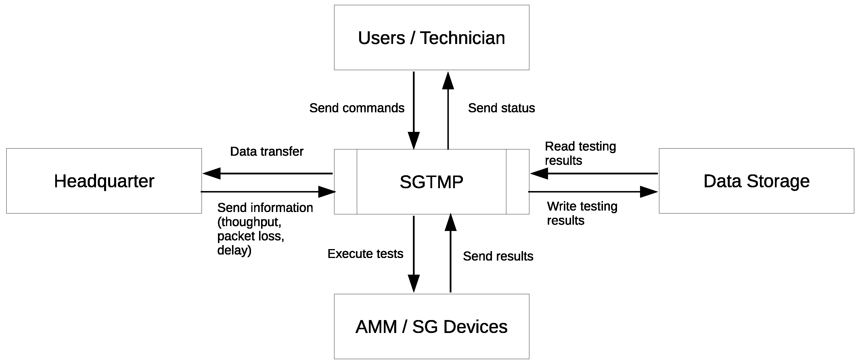
3.2. Context

The context diagram of SGTMP (Figure 2) shows the testing system interaction with other systems/actors. The main actors using the platform can be users/technicians of an SG testing laboratory that can provide commands and receive feedback about operation results. These actors can be directly on-site and provide commands to run the simulation/testing sessions. The system interacts with remote headquarters (if necessary) providing data transfer information and sending information about throughput, packet loss, and delay. SGTMP needs to interact with data storage for logs and with any data that needs to be stored to allow for reporting, monitoring, and resuming of tests/simulations performed. SGTMP interacts with either virtual/physical hardware software devices: AMM (advanced metering management) and SG devices, which cover the device discussion in the SG requirement testing part (Section 2.2).

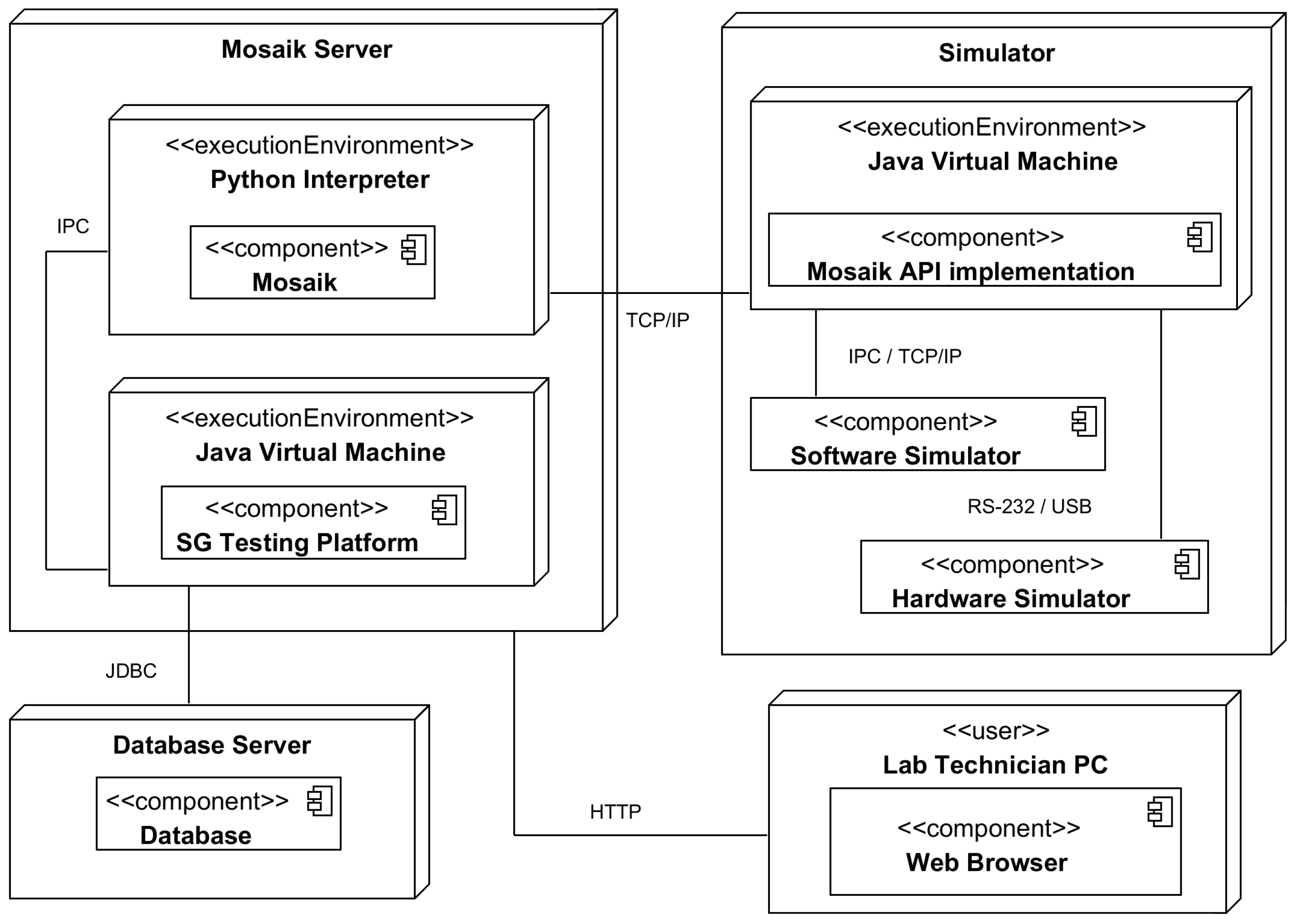
3.3. Platform Architecture

The deployment diagram shows the SGTMP design from a high-level point of view (Figure 3). The primary component is the SGTMP core module, running within the Java virtual machine. The functionality is exposed via Java and REST APIs, together with an HTTP GUI server implementing a subset of the functionality, allowing technicians to upload test definitions containing the SG topology and the test pass criteria, to schedule tests for execution and inspect the results in a visual form. On the same server, the Mosaik interface must be running to support a connection to the Mosaik framework via inter-process communication (IPC). The Mosaik interface, along with Mosaik, is responsible for communication with other simulators. Each simulator must implement the Mosaik API to be able to communicate with Mosaik. The implementation of the Mosaik API takes care of communication and data exchange with both software and hardware simulators. Software simulators can be running on the same machine, or they can be accessed remotely: the Mosaik API implementation serves only as a bridge between them. Hardware simulators can be connected to the simulator via a hardware interface (e.g., RS-232, Ethernet, USB), and the API implementation is responsible for managing the connection and other administrative tasks. The database server is a data store for storing all of the related test data, which are generated before, during, and after each test run. The connection between SGTMP and the database is handled by Java Database Connectivity (JDBC).
In the next sections, we discuss the main implementation details of SGTMP, first covering the testing management part and how tests are modeled, run, and executed. In the second part, we include the integration of simulations within the platform through the Mosaik framework.

3.4. Test Execution and Result Processing

A test represents only a static view of how a test should be run: without actually executing a test, no data can be gained, nor can a device be tested. A test is only a template from which test runs are made. It is a main requirement that each test can be executed under repeatable conditions, given that the data and topology remain unchanged. Once either the laboratory technician or another part of SGTMP schedules a test for execution, one or more test runs are created. This section describes what happens to each test run and how the results are evaluated both during and after each test run and simulation.

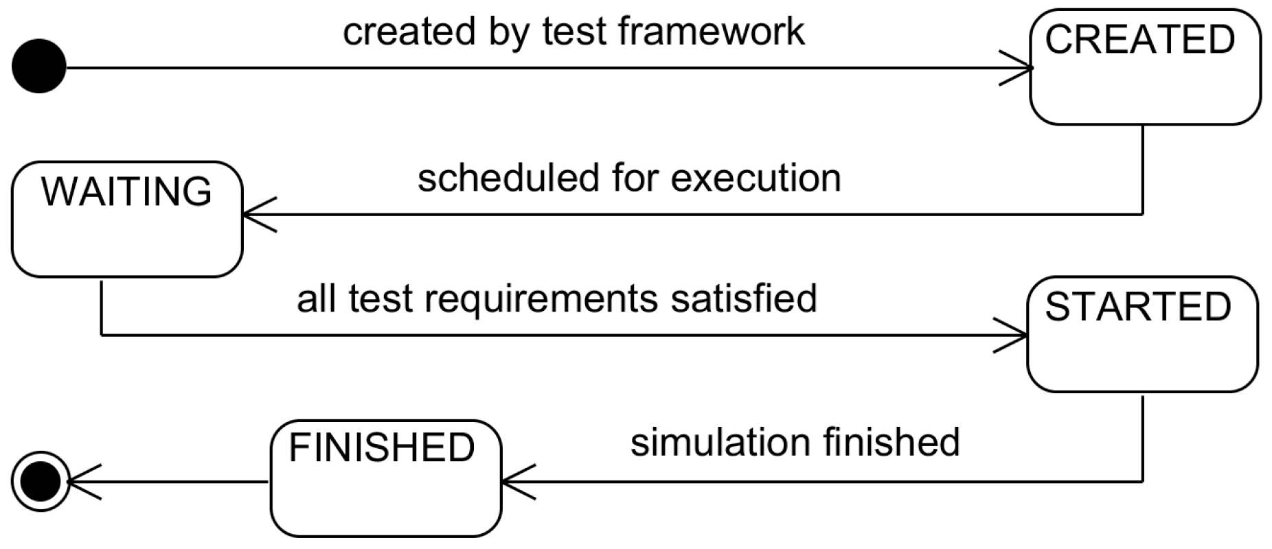
3.4.1. The Test Executor

The test executor is used to initiate the creation of each test run from a single test. All test runs are initially in the CREATED state and are waiting to be executed. The user makes a request to execute a new test, and this request is then forwarded to the test executor. After creating all of the test runs (using a strategy discussed in Section 3.4.2), the test executor then selects test run(s) that can be immediately executed. For each test run, a new testing process and any other user-specified local processes are launched. Once it is confirmed that all of the processes are successfully started or have finished (in case the process merely initiates another process), the testing task can begin. All outputs of the processes are recorded and stored along with the test run results for later review by a laboratory technician in case an incident occurred. The test executor is also capable of generating incidents if any of the setup tasks fail, which can imply that the test must be examined for possible configuration errors.

3.4.2. The Test Run Scheduler

Once a test run is created, its status is set as CREATED. Given that a single test might create several test runs, depending on the amount of configuration value permutations, it is not sufficient to start each test run as soon as it is created. Besides, each test/test run has several requirements. From the scheduling perspective, the most important are the simulator requirements, which describe the simulators that must be made available for the duration of the test run. Given that it is desirable to have as many running tests as possible at the same time, test runs must be selected so that they will not attempt to use each other’s resources, which could result in a deadlock or unpredictable simulation results. Figure 4 shows the life cycle of an individual test run. The scheduler is responsible for transitioning test runs into the STARTED stage, ideally with the best efficiency as specified by the business or SG laboratory metrics [48].
Possible selection strategies include, but are not limited to, the following:
  • Maximize test runs: This strategy tries to maximize the number of test runs that can be executed in parallel by trying to find the best combination of simulator utilization and the number of test runs. If a solution is found, the result will be the largest possible amount of test runs executed at once, at the cost of increased selection time; however, test case generation plays a role in the extensiveness of the test results [49].
  • Maximize simulator usage: This strategy is a complement of the “Maximize test runs” strategy. Here the amount of simulators (resources) is maximized per each test. The reason might be that tests with more simulators are more important (integration tests as opposed to single simulator tests).
  • OS scheduling-based: This strategy uses well-known OS scheduling algorithms for selecting test runs to execute. The simulation requirements and currently used simulators can be used to ensure fairness and resource usage optimization. All of the queued test runs for execution are considered.
  • Heuristics-based: This strategy uses different metrics from the ones described above for prioritizing test runs, such as risk or business importance. This aspect can be the Feature priority, where the highest priority features would be selected first, using a secondary selection strategy for selecting a test that currently has all of the available resources. Other metrics, such as the maximization of diagnostic information available per test [50], can be considered.
For all scheduling algorithms, one important consideration is that the tests involve simulations, and as such tests cannot be paused once started, only aborted and transitioned to the finished state. Given the time complexity of the “Maximize test runs” and “Maximize simulator usage” strategies, dynamically selected strategy combinations could be used. For more complex scenarios, another process could attempt to pre-compute an optimal solution, taking into account the expected run-time of currently running tests and the timeliness of another test run to be executed. The process of test launching can be repeated until there are no more available test runs to perform.

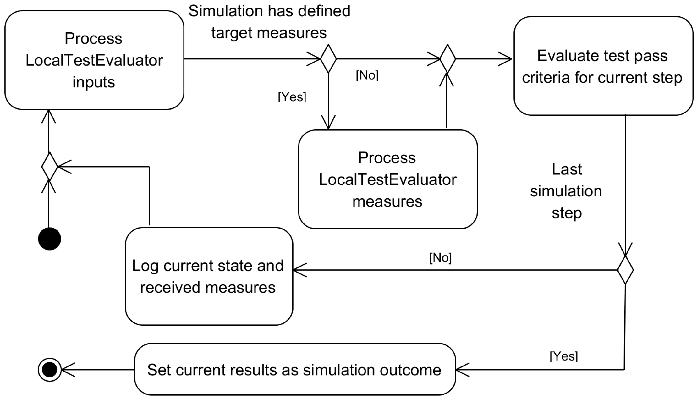
3.4.3. Local Test Evaluators

The local test evaluator is either a separate process with one specific task or another model attached to an existing simulator. In both cases, the local test evaluator is responsible for evaluating the state of its attached model(s) and reporting the step-by-step status as pass/fail to the global test evaluator via standard wire connections. Furthermore, it can send measures to the global test evaluator if it is desirable to have a finer reporting resolution of what happened during each test step. It is advantageous to make local test evaluators part of a simulator to reduce the communication overhead and possibly access internal data that might otherwise have to be transmitted across simulators.

3.4.4. Global Test Evaluators

The global test evaluator is an SGTMP entity which is responsible for gathering all the inputs from local test evaluators. These inputs include their test status and current measures (if supported by a given local test evaluator). In each step, the state of all of the local test evaluators is observed; if all of them indicate a test pass, the global simulator will also indicate a test pass. If there are expected measures that have been set for a given step, they will be evaluated against the received measures from local test evaluators. Together, the combination of measures being in range and the test status indicates whether a simulation completed successfully or not. At the end of the simulation, the simulation results are stored so that they can be read back by the laboratory technician (Figure 5).

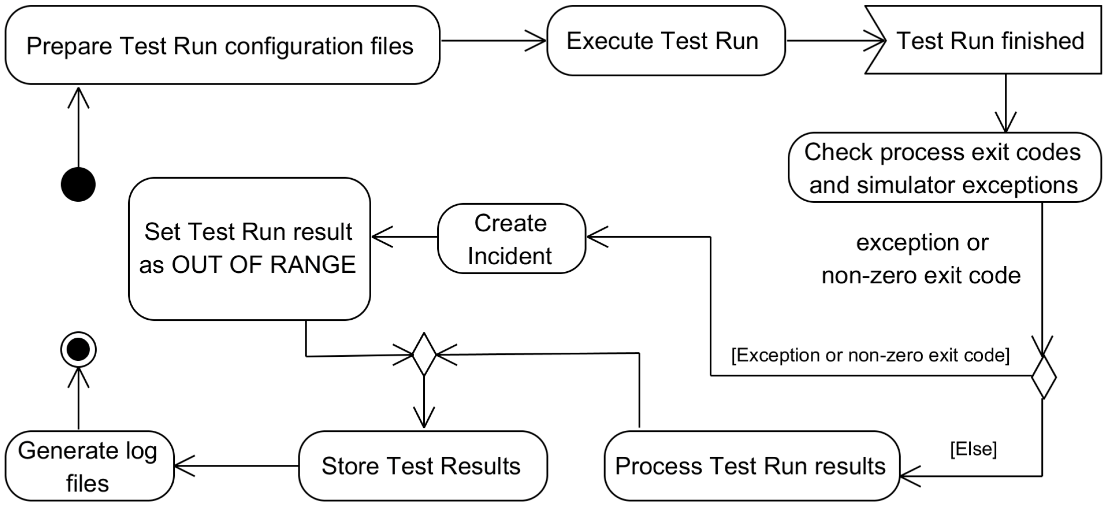
3.4.5. Test Result Processing

Test result processing consists of determining if any incidents occurred during the test run and reading back the global test evaluator results. Incidents at this stage are created for different reasons, like an exception during test execution, no result files found, indicating that the global test evaluator crashed, and/or non-zero return codes of any launched process. Should an incident occur, the test run result is marked as OUT OF RANGE to indicate that the test did not finish as expected. If there were no incidents, the global test evaluator’s final results are processed, and the test run state is set as FINISHED. The user can then view the results at a later time (Figure 6).

3.4.6. Boundary Value Testing

Following the ISO/IEC/IEEE 29119 standard [33], we added a way for the user to specify test boundary values and then run the same set of tests while only changing one value, while keeping the others constant [51]. In this framework, this is made possible by the use of TestTemplateParameters, where the user can specify either the boundary values (their minimum and maximum) or string literals, which will be used as the test parameters. Since each test can have multiple TestTemplateParameters and each TestTemplateParameter might yield several possibilities, all of their permutations must be generated for each test; therefore, each new test execution may produce several test runs with different parameter values from the value domain of each template value.

3.4.7. Logging

A test run can run for hours or even days. It is a requirement to have more information about a test run than only a simple pass/fail result. Certain conditions may be hard to re-create reliably (combination of several factors) or too time-consuming to run again (e.g., fault manifests only after running a simulation for multiple days), or equipment might get damaged in the process, and the technician must determine the exact cause of this failure from only the data which survived. For these purposes, a logging framework was added to SGTMP. There are three parts of the logging framework: test measurement logging, simulator local logging, and Mosaik logging.
Logging of measurements is done by the global test evaluator, which receives all of the tracked measures for each step and is responsible for evaluating whether they are within the specified range for each step, as specified by the relationship between test step and the expected result. In addition to evaluating measures, the component also logs them. These measures are then saved to the database for future analysis, which can be done for each test step. By allowing the users to view all of the measures during a test run, it is possible to determine the state of each testing component for any given step in time.
Each simulator is responsible for logging additional non-measure-related information. If the simulator was launched by SGTMP, the log file will be directly accessible to the user. Simulators started and managed outside of SGTMP must handle their log file.
The final logging component is from the Mosaik framework itself. If a simulation unexpectedly crashes or does not finish, this should be the first log examined. It should contain information regarding which simulators crashed, whether there were any configuration errors or whether Mosaik process itself crashed. This log is available immediately after the Mosaik process quits.

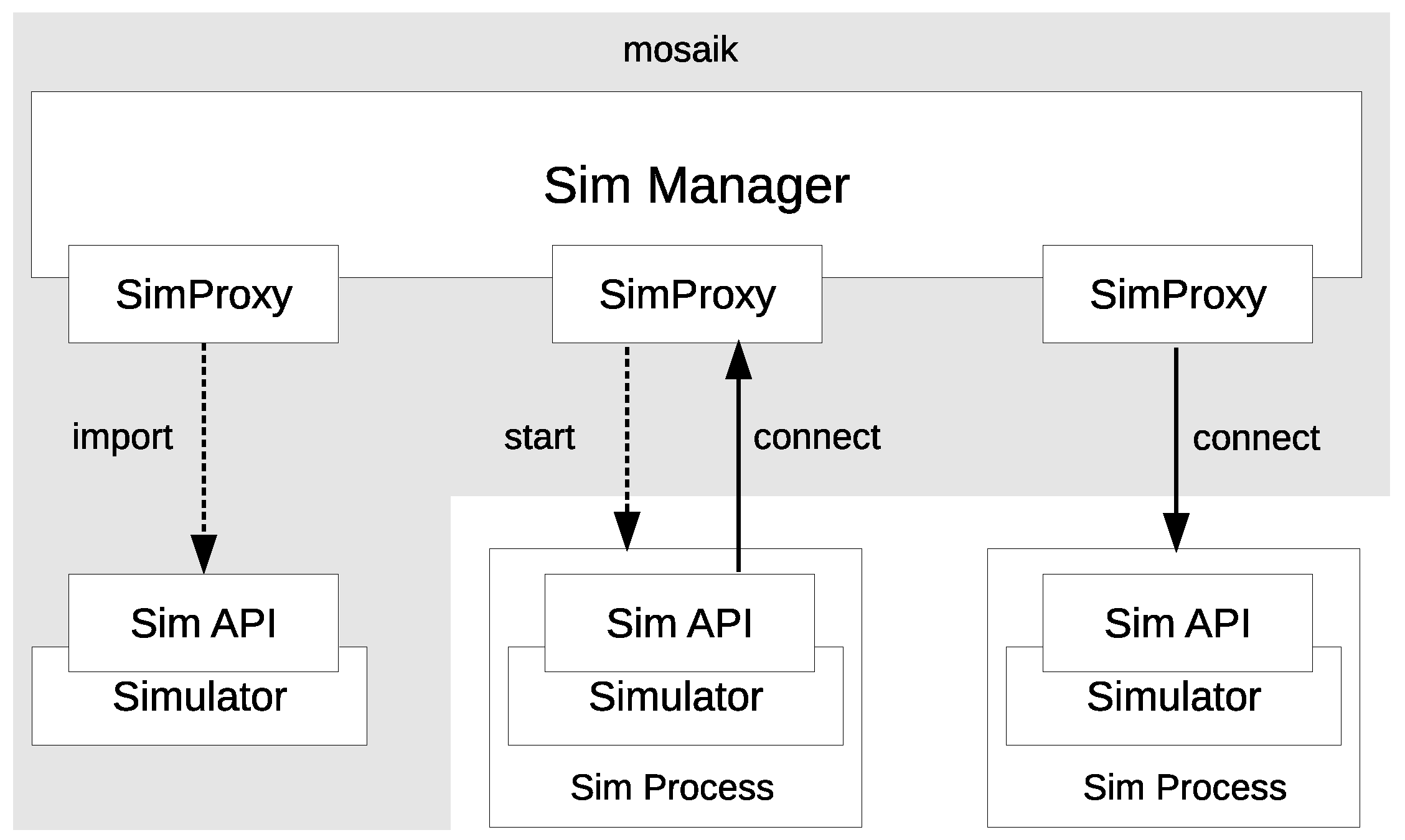
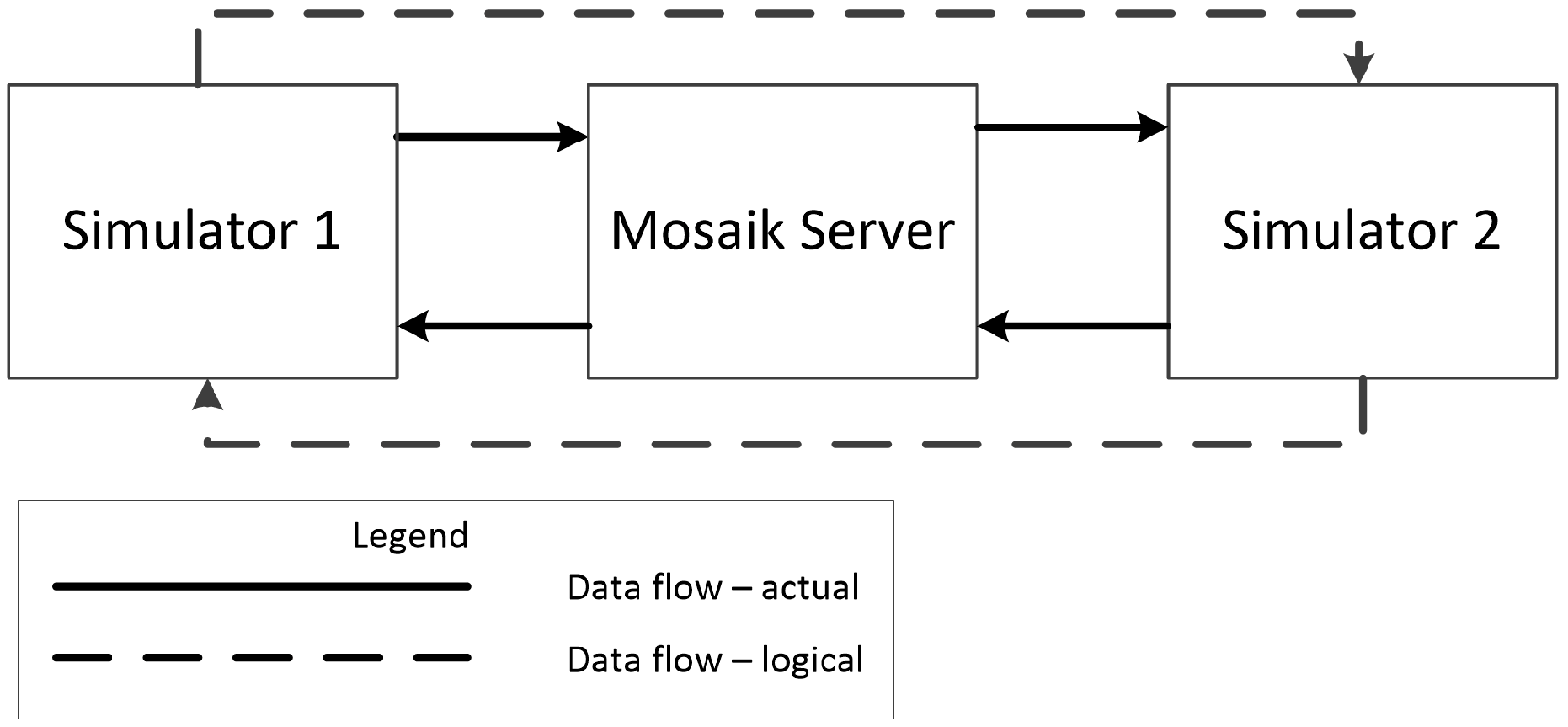
3.5. The Mosaik Co-Simulation Framework

Mosaik is an open-source co-simulation framework written primarily in Python [20,21]. It aims to allow for the connection of multiple independent SG simulation entities into one centralized simulation grid. In this simulation grid, Mosaik takes care of all of the data exchange between the simulation entities and ensures simulator time-frame synchronization. Time-frame synchronization is a crucial feature for all hardware-in-the-loop (HIL) testing frameworks, as all simulation entities can run with variable update rate ranging from once every few milliseconds to minutes or hours [42]. By ensuring time-frame synchronization, all simulation entities can send and receive data from each other without having to worry about the liveness of the received data. This behavior of Mosaik is classified as discrete-event simulation [11], since each simulator runs in its process and receives events signaling the arrival of new data or a request to send data elsewhere.
Mosaik provides a way to connect several independent simulators into one simulation by providing a single API for the user-supplied simulators (Figure 7). A simulator handles input/output sharing via the low/high-level API. Each simulator can have multiple models, and each model can have multiple instances. An example of a simulator can be a program that manages the runtime of several models or an application that interfaces with one or several hardware components. An example of a model can be software simulation of a PV panel given a set of input parameters or the individual hardware components. For some simulation models, allowing various model creations is not possible (e.g., if there is only one hardware component available and concurrent access is forbidden). For purely software-based simulators, care must be taken to ensure the given simulator can handle all of the parallel model processing.
One of the key advantages of Mosaik is its ability to integrate almost any simulator into the simulation by implementing the Mosaik API for each simulator. If the user implements the API for their simulator, the simulator could be almost anything, even a gateway to a completely different simulation framework such as Simulink (https://www.mathworks.com/products/simulink.html). Thus in practice, it is possible to combine several simulation frameworks using Mosaik as the primary data exchange framework. For example, in Mets et al. [53], the possibility of having self-contained Simulink simulators of photovoltaic panels is discussed along with methods for integration of the Simulink simulation model into Mosaik, where power grid entities can be simulated, either by native Mosaik simulators or with user-defined simulators.
The Mosaik framework provides a conceptual abstraction of connecting different simulators, which allows the user to view all of the simulators as directly connected (Figure 8, logical data flow). However, due to the need to ensure that data and individual simulation time frames are synchronized, data must be sent to the central Mosaik server, which takes care of distributing it to the designated model at the appropriate time. Thus, the real model inside the framework is different (Figure 8, actual data flow). This approach allows transparent synchronization of both the time frames and data to be exchanged.

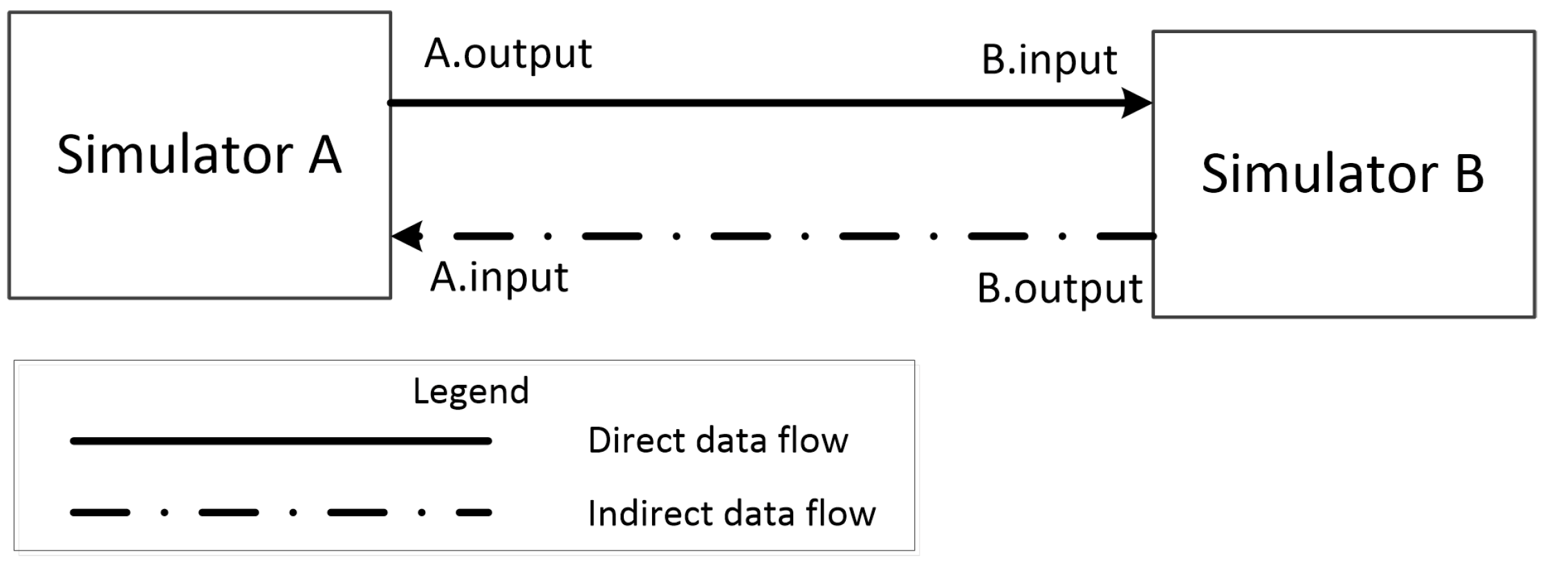
3.6. Java–Mosaik Interface

To interface with Mosaik from SGTMP, we used a process written in Python. It is launched by SGTMP as a separate process once all of the required configuration files have been generated. As an input parameter, it receives all of the configuration files necessary to start an individual simulation: simulation configuration, list of simulators, list of simulator’s models, and how the models are connected. First, the process attempts to establish a connection to all of the specified simulators, if they are an external process, or tries to start a new simulator running locally, based on user-entered parameters. Because several of these configuration files contain additional information that can be only known at runtime, they must be passed to the simulators and models during their creation in this part of the framework. In this phase, all of the asynchronous connection data for each simulator is collected and then, during their production, sent as part of additional information payload. Each simulator then receives data describing the models to create. In the next phase, all of the direct connections are connected in the Mosaik framework. If any connection contains asynchronous data, the information is extracted from the configuration files, and the connection is labeled as accepting asynchronous requests. In the last preparation phase, the simulation length and real-time requirements are entered, and afterward the simulation is started. Once the simulation is finished, either successfully or failed due to some runtime error, the process will terminate. All of the Mosaik process output is logged, including the return code: this information is then processed in SGTMP.

3.7. Configuration Generation

To support various setups of SG laboratories and their equipment, SGTMP gives the users several configuration options which can work best for their requirements. The user can define a global configuration for SGTMP, containing system information and specific setup information for each test. Such flexibility allows SGTMP to be deployed on different devices, after configuration. Internally, SGTMP converts and generates multiple configuration files for each test. The first step runs a templating engine, which allows replacing placeholder values and substituting their real values for each test run. Another essential feature is defining the SG topology for each test. Every test can have several simulators, and these simulators can have multiple models: the user is responsible for specifying how these simulators and models will be created and how they will communicate with each other. Once this is defined, SGTMP takes care of the automatic connection between these entities inside the Mosaik framework. One key addition of SGTMP is that it allows for treating both direct and asynchronous connection requests equally and for abstracting away these differences in the provided simulation API, which gives the user better simulator re-usability for multiple scenarios and SG topologies.

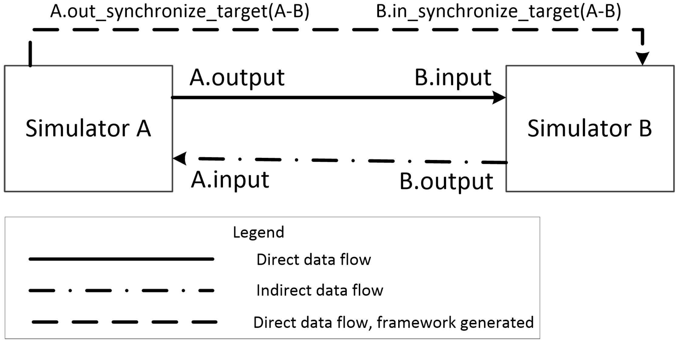
3.8. Enhanced Simulator Connection Support

The Mosaik Scenario API supports wiring two entities by specifying the following two tuples: <source model, destination model> and <output name, input name> (the details are discussed in Section 3.5). One major limitation is that no data flow cycles can be introduced into the data flow multi-graph. Mosaik uses this data flow multi-graph to keep track of the order in whichsimulators should execute their step function, and the order data should flow between the simulators. The user’s models must make asynchronous requests in code, which brings significant inflexibility should the simulation topology change. The following subsection discusses how SGTMP works around this limitation to support simulator transparent cyclic data flows.
After specifying the simulators and their models in the relevant XML configuration files, the user must define how to handle data flows between the entities. SGTMP allows specifying all connections (both direct and asynchronous) using one unified format and only specifying whether the link is direct or indirect. The implemented simulators do not need to distinguish between receiving and sending asynchronous data, as this is now handled automatically inside the AbstractSimulator. The advantage is that all of the data flows are explicitly specified in one file and are no longer tied to a specific simulation topology, which tightly couples two or more simulators together. Now all simulators are independent of the simulation topology and can be re-used in multiple tests. A conceptual model of how the user has to input topology data is in Figure 9, which shows that the user has to distinguish between direct and asynchronous wire connections. However, the user does not have to care about these two modes inside their AbstractSimulator implementation.
New input is added to both simulators (name-generated from their unique id and input names) along with a direct wire connection between them. The goal is to facilitate reverse data flow between the two entities without having to use asynchronous values for the initial data exchange. After this setup, all asynchronous data will flow through the appropriate asynchronous connection automatically (Figure 10).

3.9. Platform API

SGTMP has two methods by which a developer can interact with the system. The first one is the Java API, which exposes all of the SGTMP functionality, including test management, test pass criteria management, launching new tests, and viewing their results. The Java API interfaces directly the internal platform API to provide this functionality. The API is designed for interaction with the SGTMP domain objects in a native way. The second method is using the REST API. This method covers the same functionality as the Java API with only minor differences. These differences are primarily to facilitate more natural data representation using JSON and to follow the REST conventions in access patterns. The SGTMP web uses the REST API to access the platform’s features in a user-accessible way.

4. SGTMP Deployment Scenario—SG Component Stress Testing
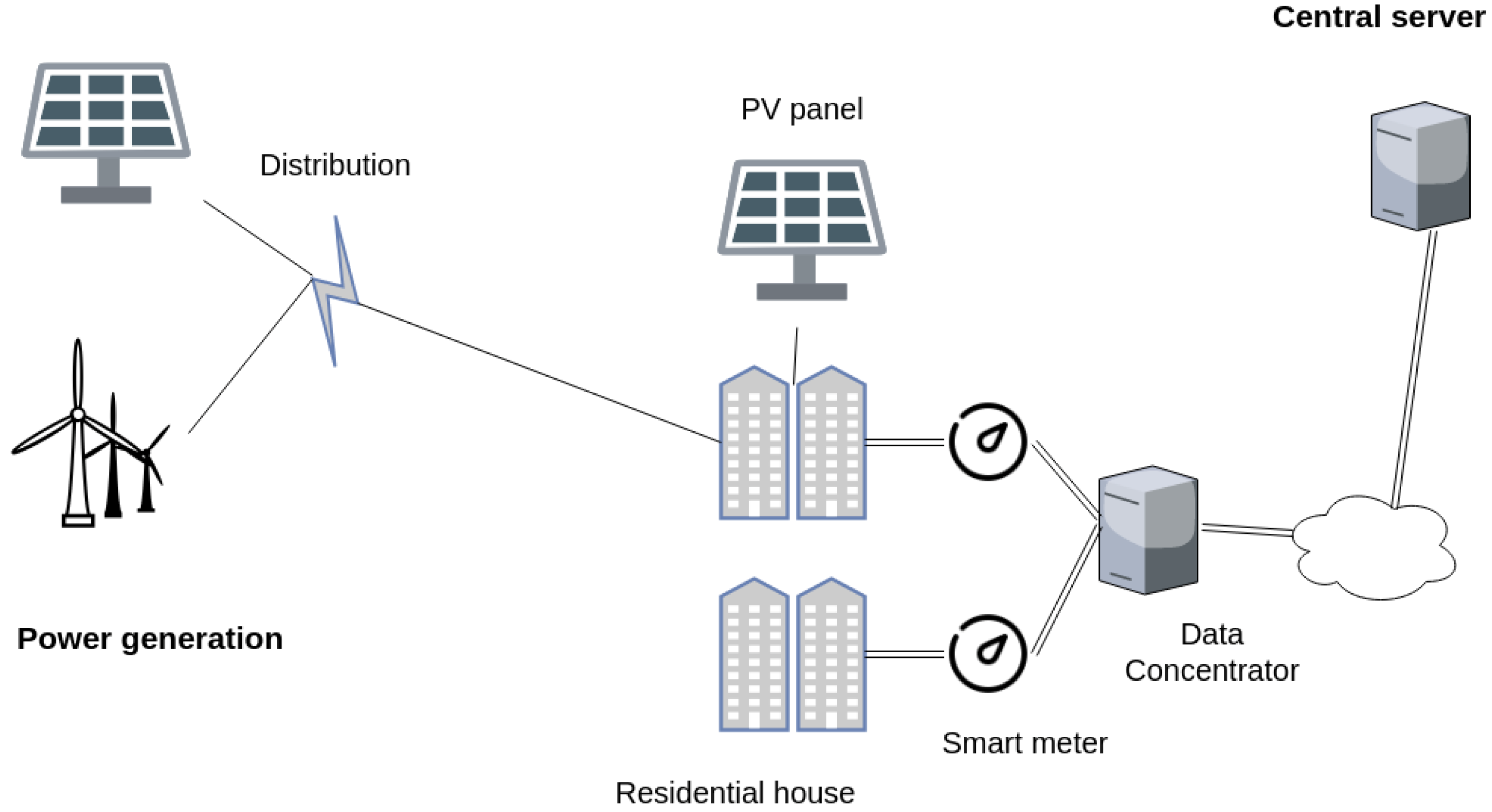
This section presents one main scenario that showcases the usage of SGTMP. The objective of this scenario is to test the interoperability of several SG components when they are connected to one SG system/environment. Because SGTMP allows data collection from every node in the system, multiple test cases can be executed during a single test simulation. Each part of the system is connected to SGTMP for data collection and command transmission.

4.1. SG Topology

The physical test topology is as follows (Figure 11):
  • Several energy sources generating electricity for the SG system. These can include photovoltaic panels, wind turbines, or power plants using non-renewable energy sources. Each of these energy sources can be created at full scale or virtualized, providing only a simulated energy production profile for other parts of the system. For example, this whole layer can be emulated through cheap hardware devices such as Arduino, as described in our previous work in Schvarcbacher and Rossi [22], providing the benefits of a quick set-up for educational needs.
  • Electric distribution lines that collect and transmit energy generated to other parts of the tested network. Depending on the system setup, transmission losses can be simulated or observed in this step.
  • Several houses in one or more neighborhoods connected to the electric distribution lines. Each home must have an SM; some can optionally have photovoltaic panels mounted on their roofs. The energy generated by them can be used inside the house or sold back to the grid.
  • Smart meter data concentrators (SMDCs) attached to the endpoints at each neighborhood. Their amount depends on the specific data collection requirements of the energy distributor.
  • The SG main server, collecting data from SMDC to run aggregated analytics on the data and respond appropriately.
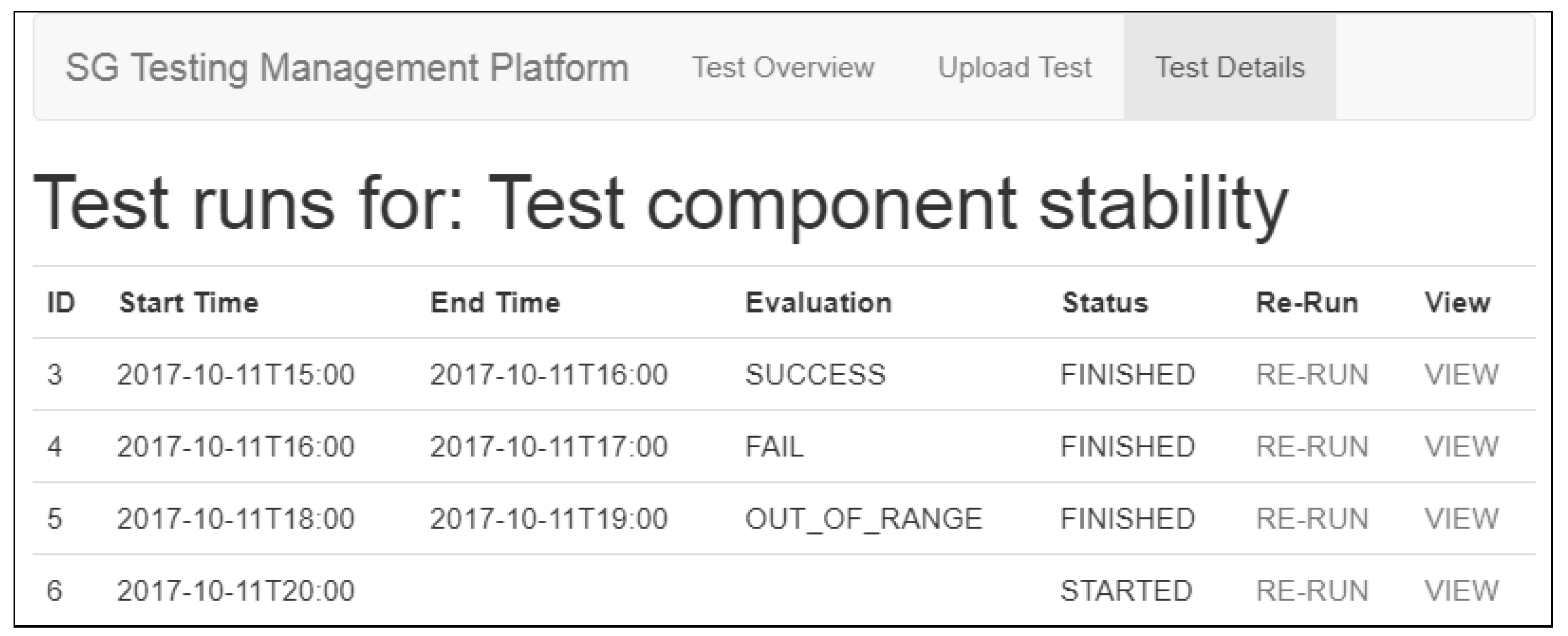
The logical test topology extends the physical one by adding an SGTMP monitoring node to each device or replaces a physical device with a simulated device controlled directly by SGTMP. For hardware devices which require inputs from other devices, these inputs can be either simulated or created by various generators controlled by an SGTMP node. A single device can be tested in isolation, where the rest of the environment is fully simulated. Using a similar principle, only certain parts of the SG topology can be simulated to remain as close as possible to real-world deployments when using hardware. Using the above-described topology, it is possible to perform different tests on each device or at a whole SG level, either per test or at once.

4.2. Test Execution

In this test, the power production is accomplished by using SGTMP controlled photovoltaic panels, based on the prototype described in Schvarcbacher and Rossi [22], where a node for testing SG components was presented. The SG topology in this scenario includes multiple power sources, energy distributors, and energy consumers. Electrical energy is created by using various power production nodes, which consist of a PV panel with an LED array enclosed in a light-proof container. Each of the LEDs is individually controllable, which enables fine-grained control of the light levels inside the container. If enough LEDs are present, a full day–night light cycle profile can be simulated with a light-level resolution depending on the possible Watt output combinations of the LEDs. The power output from the PV panel is then routed outside the container to be used in other parts of the SG system as an energy source. The power production node is a self-contained system controlled only by the simulation platform. In this way, the testing platform can have full control of the energy available for simulation in the SG. By using several of these power production nodes, it is possible to simulate a power grid from various geographical locations with different power outputs sending energy to the energy distribution network. By using an entirely controlled energy source, it is possible to simulate different weather and light conditions and in turn observe their effect on the network.
In this scenario, all systems use real hardware, with power production nodes scaled down for ease of use and setup. The power production node is similar to the one described in Schvarcbacher and Rossi [22]. SM and SMDC are prototype devices provided by an energy distribution vendor for testing. The devices are connected to both the physical energy grid and SGTMP for monitoring and control.
The main focus of this test involves the testing of the SMs attached to the houses and the SMDCs. The SMDC need to be able to handle the data collection from multiple SMs at once without losing data or crashing due to data overloading. Additionally, SMDCs must forward the received data to a central collection server in periodic intervals to enable different parts of the SG infrastructure to respond to currently happening events. Each SM in the network is instructed to send their observed data by an attached SGTMP node to their SMDC. The performance of the SMDC is examined and evaluated using criteria including data loss, maximum responses processed per unit of time, accuracy and percentage of data sent from SMDC to the central collection server. If network losses are ignored, then the SMDC should collect all of the SM data, aggregate it and forward to the central server. Depending on the energy provider criteria, these parameters should not fall below a certain threshold, under which the test is considered a failure. As an example, if the SMDC stops processing any new data from SM following a larger than expected data size (simulated overload), the vendor can be notified with the situation description including the full simulation data set for their tests.
On a low level, SGTMP must instruct the SMs to send data to the SMDC and then measure the used power coming into the house and out of the house (if PV panels are available) to verify the accuracy of data reporting. On the SMDC side, the performance of the SMDC is monitored, including the data sent out of the SMDC to confirm the correct functionality of the data collection process.

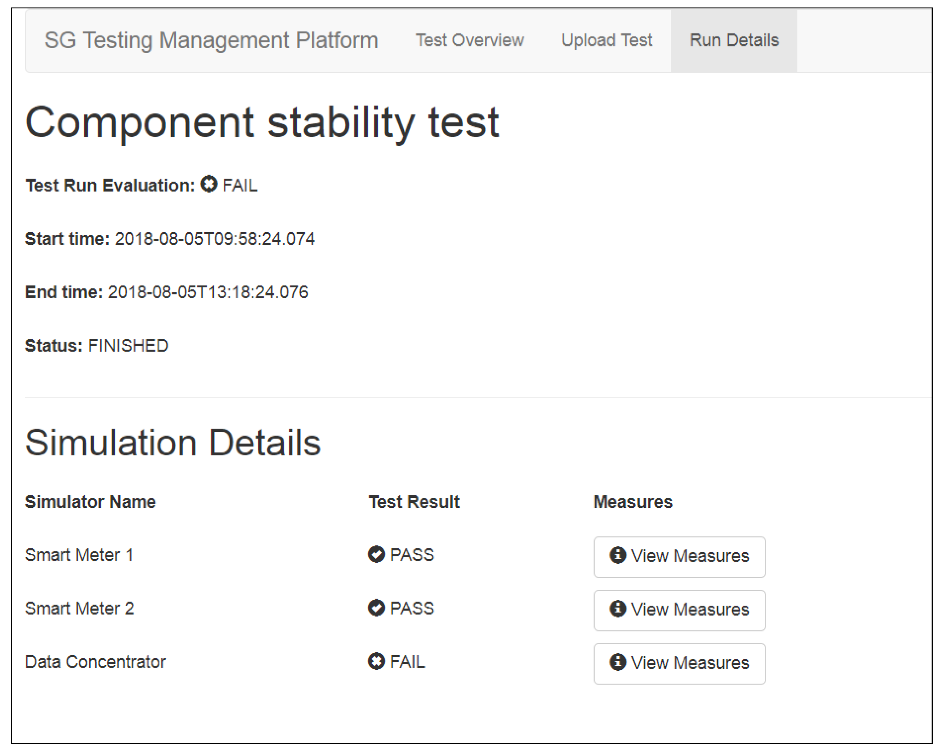
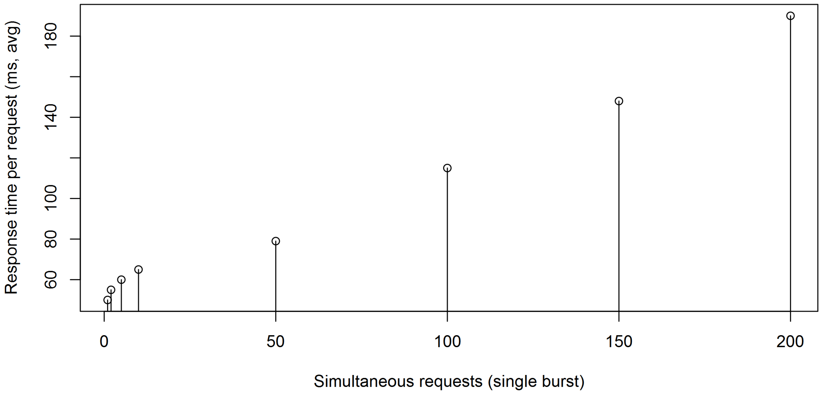
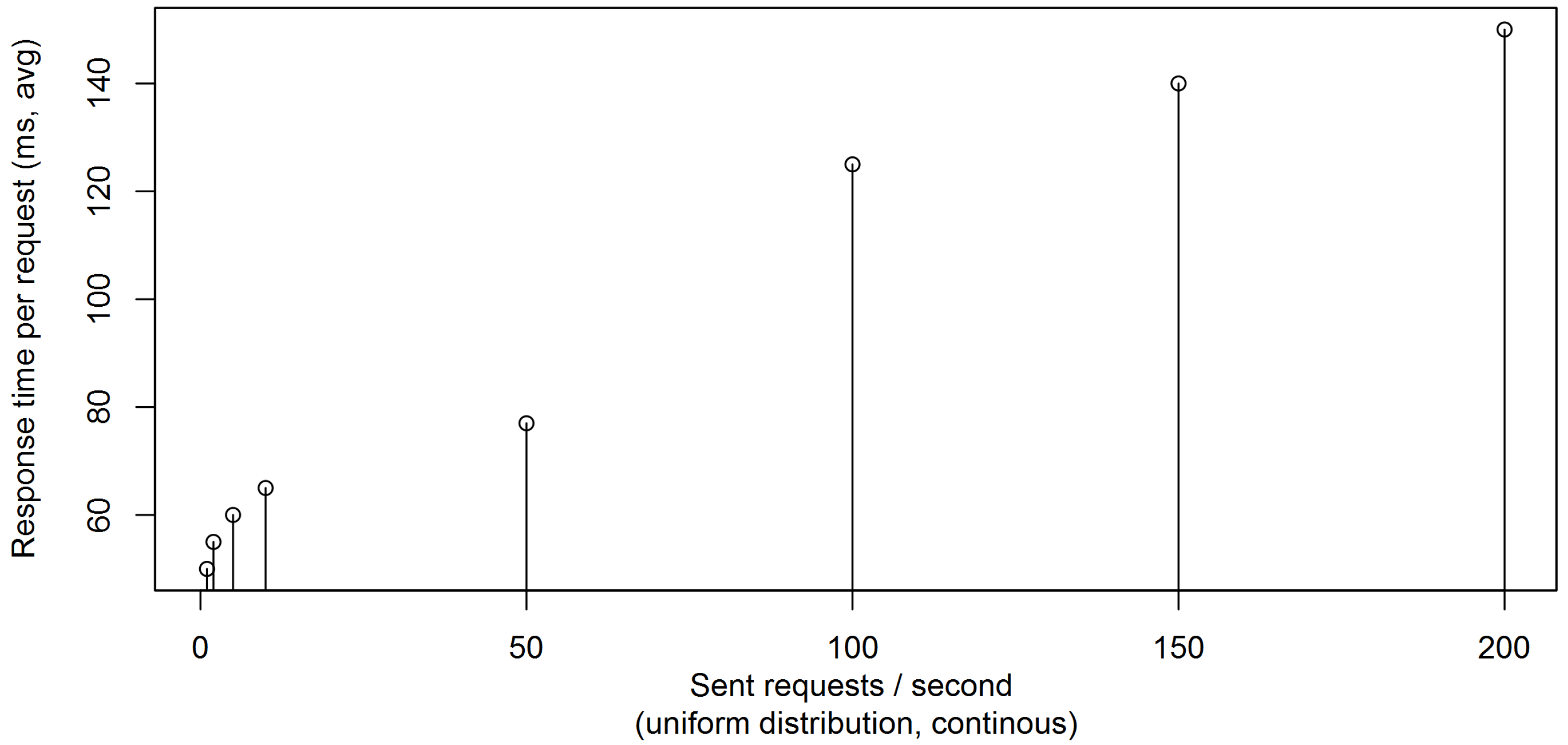
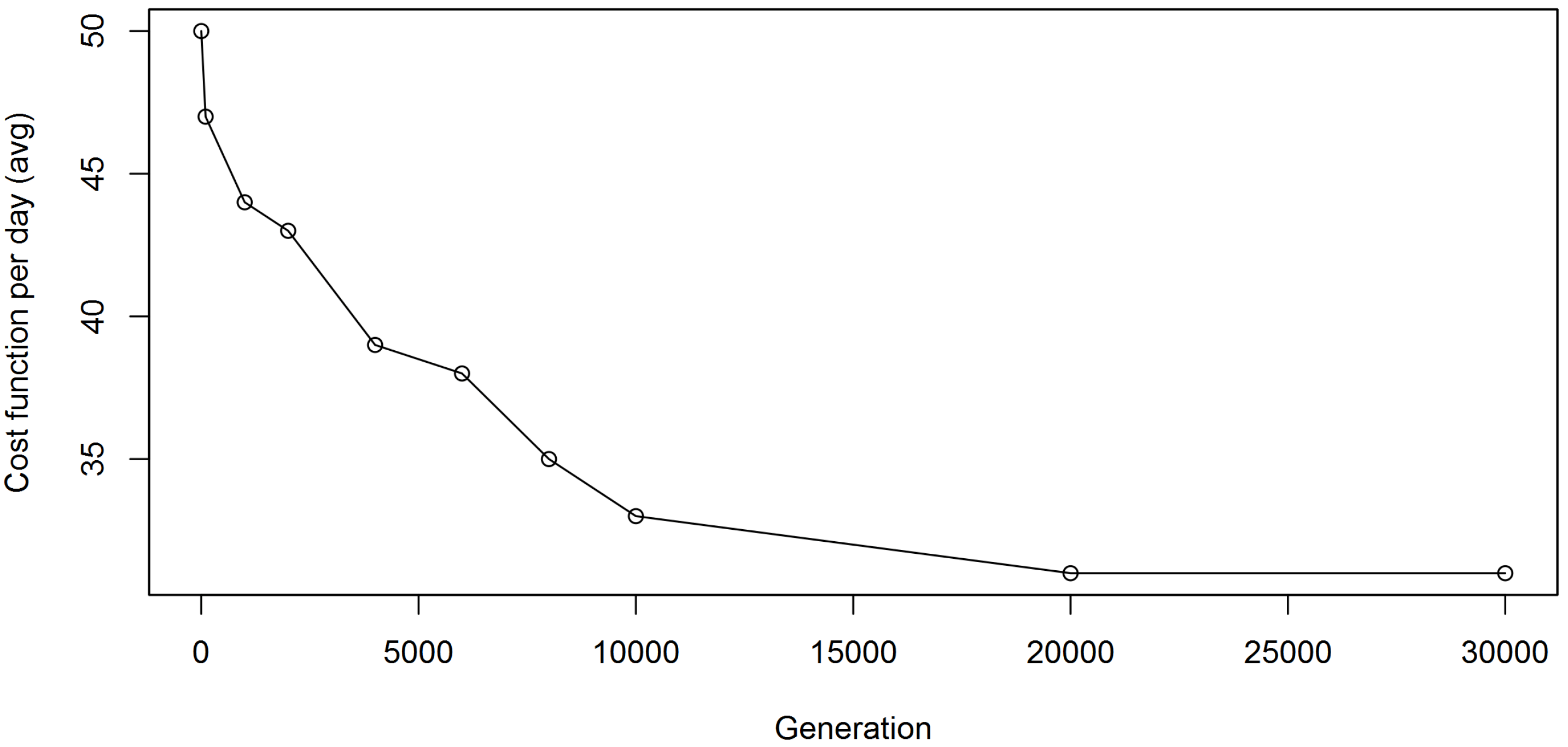
4.3. Simulation Results Overview

The user can perform all of the required tasks using a web browser in the SGTMP GUI. These include creating and editing tests along with defining their test pass criteria and the SG topology. All test definitions can be viewed and modified. From there, individual tests can be started, and their progress examined. The final results can be observed, which provides an overview of all the executed tests including their pass/fail status (Figure 12). A more detailed view, as shown in Figure 13, is also available for each test run, which contains detailed logs collected from each SGTMP node during the simulation. This data can be used to run further analysis outside of SGTMP, such as aggregation and analysis of multiple test runs using tools which are suitable for the user. This data is in JSON format to simplify the analysis of recorded data.
From the collected data, we showcase some of the results created from the observed measures. One example is testing the performance and reliability of the SMDC component under changing network conditions. For this experiment, we used a virtualized SM featuring only the necessary network communication capabilities. These SMs were then requested by SGTMP to send out their payload at the same time to the SMDC, to create a burst traffic load on the network and SMDC. The goal was to determine the behavior (response time per request and reliability) of the SMDC in the worst case scenario in which all SMs send data at once. Figure 14 shows the behavior of a single SMDC under an increasing number of burst data transmitted. Such increase in requests can be defined according to the needs of the tests.
As another example, to test the SMDC under sustained load, we used two hardware SMs connected to a single SMDC. SGTMP instructed each of the SMs to send requests to the SMDC in constant intervals, distributing the requests in a round-robin way between the two SMs. The results of an SMDC in more realistic continuous load are shown in Figure 15.

4.4. Other SGTMP Usage Scenarios

SGTMP is not only limited to the testing of real/virtualized devices. It can be used as a standalone platform to train and then verify machine learning (ML) models for SG components. One example is the development of an SM enhancement to work with variable energy prices (determined by current energy availability) throughout the day. One application is heating water inside a boiler with hot water storage for use throughout the day, optimizing for maximum instant hot water availability or hot water availability at a given time with the lowest price possible. For houses with PV panels, another variable is whether the excess energy should be sold to the grid or used for other planned household tasks. The SG topology in SGTMP for training consists of a power grid providing current energy prices (to which power from PV panel units can be sold), a single SM, an electric water heater with water storage tank, and an optional PV panel unit. The advantage is that, in this setup, there are no hardware components and it is possible to run faster than real-time, allowing quicker data generation. The generated data can be used to train the ML model either off-line, using the data captured in SGTMP or training can be done during an SGTMP test run.
The result of training an ML model using a single SM is shown in Figure 16, which shows how each generation progressed in optimizing the cost function. The model was trained to optimize the cost function, which was the total amount of currency used to heat the water and amount of water above the required minimum for use in other household requirements. Models not meeting the minimum level of water needed at the required time in the day cycle were penalized. The training data was based on taking the prices of electricity in a fixed region over a one-week period with one-hour resolution and cycling this data for the duration of the supervised learning period. Once the learning phase was completed, the resulting model was fixed and placed into a development model of an SM. SGTMP was then used to verify the new SM algorithm for controlling linked smart home appliances—in this case, the water heater based on the state of the energy grid. In the future, we could expand this model to add more input variables to the model and control multiple smart appliances at the same time. This scenario demonstrates how SGTMP can be used for the initial SM prototype development inside an SG, using SGTMP in the first phase to gather data and in the second phase to verify the application of the prototype inside the created SG topology.

5. Conclusions

In this paper, we introduced a smart grid testing management platform (herein referred to as SGTMP) for the execution of real-time hardware-in-the-loop SG tests and simulations that can help to improve the overall reliability, resilience, availability, integration, and security of the SG infrastructure. SGTMP is composed of a Mosaik interface written in Python and a Java-based testing platform that includes test definition, management, scheduling, execution, visualization, and other aspects supported by a web-based interface. We presented the central architecture, the testing management components, and co-simulation interfacing, together with the usage of the platform through an SG component stress testing scenario. Furthermore, we discussed briefly further scenarios (e.g., data model verification/optimization) that can extend the benefits of real/virtualized devices testing provided by SGTMP.
There are several enhancements for SGTMP that are under evaluation, such as the addition of a domain-specific language (DSL) for the configuration (similarly to Nägele and Hooman [54], Nägele et al. [55]), allowing more natural creation and understanding of the models, resulting in faster development of simulation/testing scenarios. Another direction is to evaluate other co-simulation frameworks, looking at the implications for the interaction with power and communication simulators. Many co-simulation frameworks can be considered [13], however, they differ by several criteria, like the type of synchronization offered (discrete events, time stepped, etc...), or like the degree of real-time and HIL support—among other characteristics. Giving support to other co-simulation frameworks can make SGTMP more flexible, at the expense of increased complexity.

Author Contributions

Conceptualization, M.S. and B.R.; Methodology, M.S. and K.H.; Software, M.S.; Supervision, B.R.; Visualization, M.S.; Writing—original draft, M.S., K.H., and B.R.; Writing—review & editing, B.R. and T.P.

Funding

The research was supported by ERDF/ESF “CyberSecurity, CyberCrime and Critical Information Infrastructures Center of Excellence” (No. CZ.02.1.01/0.0/0.0/16_019/0000822).

Conflicts of Interest

The authors declare no conflict of interest.

Abbreviations

The following abbreviations are used in this manuscript:
SGSmart Grid
SGTMPSmart Grid Testing Management Platform
SMSmart Meter
SMDCSmart Meter Data Concentrator
AMMAdvanced Metering Management
HILHardware-In-the-Loop
RESTREpresentational State Transfer
HTTPHyperText Transfer Protocol
GUIGraphical User Interface
APIAdvanced Programming Interface
IPCInter-Process Communication

References

  1. Farhangi, H. The path of the smart grid. IEEE Power Energy Mag. 2010, 8, 18–28. [Google Scholar] [CrossRef]
  2. Lopez, J.; Rubio, J.E.; Alcaraz, C. A Resilient Architecture for the Smart Grid. IEEE Trans. Ind. Inform. 2018, 14, 3745–3753. [Google Scholar] [CrossRef]
  3. Fang, X.; Misra, S.; Xue, G.; Yang, D. Smart grid—The new and improved power grid: A survey. IEEE Commun. Surv. Tutor. 2012, 14, 944–980. [Google Scholar] [CrossRef]
  4. Chren, S.; Rossi, B.; Pitner, T. Smart grids deployments within EU projects: The role of smart meters. In Proceedings of the 2016 IEEE Smart Cities Symposium Prague (SCSP), Prague, Czech Republic, 26–27 May 2016; pp. 1–5. [Google Scholar]
  5. Yan, Y.; Qian, Y.; Sharif, H.; Tipper, D. A Survey on Smart Grid Communication Infrastructures: Motivations, Requirements and Challenges. IEEE Commun. Surv. Tutor. 2012, 15, 5–20. [Google Scholar] [CrossRef] [Green Version]
  6. Young, M. Software Testing and Analysis: Process, Principles, And Techniques; John Wiley & Sons: Hoboken, NJ, USA, 2008. [Google Scholar]
  7. Možucha, J.; Rossi, B. Is Mutation Testing Ready to Be Adopted Industry-Wide? In Proceedings of the International Conference on Product-Focused Software Process Improvement, Trondheim, Norway, 22–24 November 2016; Springer: Berlin, Germany,, 2016; pp. 217–232. [Google Scholar]
  8. Rossi, B.; Russo, B.; Succi, G. Modelling failures occurrences of open source software with reliability growth. In Proceedings of the IFIP International Conference on Open Source Systems, Notre Dame, IN, USA, 30 May–2 June 2010; Springer: Berlin, Germany, 2010; pp. 268–280. [Google Scholar]
  9. CEN-CENELEC-ETSI, Smart Grid Coordination Group. Available online: https://ec.europa.eu/energy/sites/ener/files/documents/xpert_group1_reference_architecture.pdf (accessed on 16 September 2018).
  10. Chren, S.; Rossi, B.; Bühnova, B.; Pitner, T. Reliability data for smart grids: Where the real data can be found. In Proceedings of the 2018 Smart City Symposium Prague (SCSP), Prague, Czech Republic, 24–25 May 2018. [Google Scholar]
  11. Palensky, P.; Widl, E.; Elsheikh, A. Simulating cyber-physical energy systems: Challenges, tools and methods. IEEE Trans. Syst. Man Cybern. Syst. 2014, 44, 318–326. [Google Scholar] [CrossRef]
  12. Khaitan, S.K.; McCalley, J.D. Design techniques and applications of cyberphysical systems: A survey. IEEE Syst. J. 2015, 9, 350–365. [Google Scholar] [CrossRef]
  13. Vogt, M.; Marten, F.; Braun, M. A survey and statistical analysis of smart grid co-simulations. Appl. Energy 2018, 222, 67–78. [Google Scholar] [CrossRef]
  14. Song, W.Z.; De, D.; Tan, S.; Das, S.K.; Tong, L. A wireless smart grid testbed in lab. IEEE Wirel. Commun. 2012, 19, 58–64. [Google Scholar] [CrossRef]
  15. Anderson, D.; Zhao, C.; Hauser, C.; Venkatasubramanian, V.; Bakken, D.; Bose, A. Intelligent Design Real-Time Simulation for Smart Grid Control and Communications Design. IEEE Power Energy Mag. 2012, 10, 49–57. [Google Scholar] [CrossRef]
  16. Tan, S.; Song, W.Z.; Dong, Q.; Tong, L. Score: Smart-grid common open research emulator. In Proceedings of the 2012 IEEE Third International Conference on Smart Grid Communications (SmartGridComm), Tainan, Taiwan, 5–8 November 2012; pp. 282–287. [Google Scholar]
  17. Annor-Asante, M.; Pranggono, B. Development of smart grid testbed with low-cost hardware and software for cybersecurity research and education. Wirel. Pers. Commun. 2018, 101, 1357–1377. [Google Scholar] [CrossRef]
  18. Chassin, D.P.; Schneider, K.; Gerkensmeyer, C. GridLAB-D: An open-source power systems modeling and simulation environment. In Proceedings of the Transmission and Distribution Conference and Exposition, Chicago, IL, USA, 21–24 April 2008; pp. 1–5. [Google Scholar]
  19. Steinbrink, C.; Schlögl, F.; Babazadeh, D.; Lehnhoff, S.; Rohjans, S.; Narayan, A. Future perspectives of co-simulation in the smart grid domain. In Proceedings of the 2018 IEEE International Energy Conference (ENERGYCON), Limassol, Cyprus, 3–7 June 2018. [Google Scholar]
  20. Büscher, M.; Claassen, A.; Kube, M.; Lehnhoff, S.; Piech, K.; Rohjans, S.; Scherfke, S.; Steinbrink, C.; Velasquez, J.; Tempez, F.; et al. Integrated Smart Grid simulations for generic automation architectures with RT-LAB and mosaik. In Proceedings of the 2014 IEEE International Conference on Smart Grid Communications (SmartGridComm), Venice, Italy, 3–6 November 2014; pp. 194–199. [Google Scholar]
  21. Schloegl, F.; Rohjans, S.; Lehnhoff, S.; Velasquez, J.; Steinbrink, C.; Palensky, P. Towards a classification scheme for co-simulation approaches in energy systems. In Proceedings of the 2015 International Symposium on Smart Electric Distribution Systems and Technologies (EDST), Vienna, Austria, 8–11 September 2015; pp. 516–521. [Google Scholar]
  22. Schvarcbacher, M.; Rossi, B. Smart Grids Co-Simulations with Low-Cost Hardware. In Proceedings of the 2017 43rd Euromicro Conference on Software Engineering and Advanced Applications (SEAA), Vienna, Austria, 30 August–1 Septemer 2017; pp. 252–255. [Google Scholar]
  23. Rossi, B.; Chren, S.; Buhnova, B.; Pitner, T. Anomaly detection in smart grid data: An experience report. In Proceedings of the 2016 IEEE International Conference on Systems, Man, and Cybernetics (SMC), Budapest, Hungary, 9–12 October 2016; pp. 2313–2318. [Google Scholar]
  24. Liu, X.; Golab, L.; Golab, W.M.; Ilyas, I.F. Benchmarking Smart Meter Data Analytics. In Proceedings of the 18th International Conference on Extending Database Technology, EDBT 2015, Brussels, Belgium, 23–27 March 2015; pp. 385–396. [Google Scholar]
  25. Hebner, R. Nanogrids, Microgrids, and Big Data: The Future of the Power Grid. Available online: https://spectrum.ieee.org/energy/renewables/nanogrids-microgrids-and-big-data-the-future-of-the-power-grid (accessed on 8 August 2018).
  26. Kok, K.; Karnouskos, S.; Ringelstein, J.; Dimeas, A.; Weidlich, A.; Warmer, C.; Drenkard, S.; Hatziargyriou, N.; Lioliou, V. Field-testing smart houses for a smart grid. In Proceedings of the 21st International Conference and Exhibition on Electricity Distribution (CIRED 2011), Frankfurt, Germany, 6–9 June 2011. [Google Scholar]
  27. Karnouskos, S.; Holanda, T.N.D. Simulation of a Smart Grid City with Software Agents. In Proceedings of the 2009 Third UKSim European Symposium on Computer Modeling and Simulation, Athens, Greece, 25–27 November 2009; pp. 424–429. [Google Scholar]
  28. Wang, Z.; Scaglione, A.; Thomas, R.J. Generating Statistically Correct Random Topologies for Testing Smart Grid Communication and Control Networks. IEEE Trans. Smart Grid 2010, 1, 28–39. [Google Scholar] [CrossRef]
  29. Hahn, A.; Ashok, A.; Sridhar, S.; Govindarasu, M. Cyber-Physical Security Testbeds: Architecture, Application, and Evaluation for Smart Grid. IEEE Trans. Smart Grid 2013, 4, 847–855. [Google Scholar] [CrossRef]
  30. Pipattanasomporn, M.; Feroze, H.; Rahman, S. Multi-agent systems in a distributed smart grid: Design and implementation. In Proceedings of the Power Systems Conference and Exposition, Seattle, WA, USA, 15–18 March 2009; pp. 1–8. [Google Scholar]
  31. Oliveira, P.; Pinto, T.; Morais, H.; Vale, Z. MASGriP—A multi-agent smart grid simulation platform. In Proceedings of the Power and Energy Society General Meeting, San Diego, CA, USA, 22–26 July 2012; pp. 1–8. [Google Scholar]
  32. Afzal, W.; Alone, S.; Glocksien, K.; Torkar, R. Software test process improvement approaches: A systematic literature review and an industrial case study. J. Syst. Softw. 2016, 111, 1–33. [Google Scholar] [CrossRef]
  33. JTC1/SC7, I. ISO/IEC/IEEE 29119 Software Testing Standard. Available online: https://www.iso.org/standard/45142.html (accessed on 12 September 2018).
  34. Garcia, C.; Dávila, A.; Pessoa, M. Test Process Models: Systematic Literature Review. In Communications in Computer and Information Science; Springer: Cham, Switzerland, 2014; pp. 84–93. [Google Scholar]
  35. Garousi, V.; Felderer, M.; Hacaloğlu, T. Software test maturity assessment and test process improvement: A multivocal literature review. Inf. Softw. Technol. 2017, 85, 16–42. [Google Scholar] [CrossRef]
  36. Garousi, V.; Felderer, M.; Hacaloğlu, T. What we know about software test maturity and test process improvement. IEEE Softw. 2017, 35, 84–92. [Google Scholar] [CrossRef]
  37. Swinkels, R. A Comparison of TMM and Other Test Process Improvement Models; Technical Report; Frits Philips Institute, Technische Universiteit: Eidhoven, The Netherlands, 2000; Volume 51. [Google Scholar]
  38. Farooq, A.; Dumke, R.R. Evaluation Approaches in Software Testing; Technical Report; Otto von Guericke University of Magdeburg: Magdeburg, Germany, 2008. [Google Scholar]
  39. Farooq, A. An Evaluation Framework for Software Test Processes. Ph.D. Thesis, Otto von Guericke University of Magdeburg, Magdeburg, Germany, 2009. [Google Scholar]
  40. Abdou, T.; Grogono, P.; Kamthan, P. Managing Corrective Actions to Closure in Open Source Software Test Process. In Proceedings of the 25th International Conference on Software Engineering and Knowledge Engineering, Boston, MA, USA, 27–29 June 2013. [Google Scholar]
  41. Felderer, M.; Ramler, R. Integrating risk-based testing in industrial test processes. Softw. Qual. J. 2014, 22, 543–575. [Google Scholar] [CrossRef]
  42. Gomes, C.; Thule, C.; Broman, D.; Larsen, P.G.; Vangheluwe, H. Co-simulation: State of the art. arXiv, 2017; arXiv:1702.00686. [Google Scholar]
  43. Bian, D.; Kuzlu, M.; Pipattanasomporn, M.; Rahman, S.; Wu, Y. Real-time co-simulation platform using OPAL-RT and OPNET for analyzing smart grid performance. In Proceedings of the Power & Energy Society General Meeting, Denver, CO, USA, 26–30 July 2015; pp. 1–5. [Google Scholar]
  44. Li, W.; Ferdowsi, M.; Stevic, M.; Monti, A.; Ponci, F. Cosimulation for smart grid communications. IEEE Trans. Ind. Inform. 2014, 10, 2374–2384. [Google Scholar] [CrossRef]
  45. Li, W.; Zhang, X. Simulation of the smart grid communications: Challenges, techniques, and future trends. Comput. Electr. Eng. 2014, 40, 270–288. [Google Scholar] [CrossRef]
  46. Varga, A.; Hornig, R. An overview of the OMNeT++ simulation environment. In Proceedings of the 1st International Conference on Simulation Tools and Techniques for Communications, Networks and Systems & Workshops, Marseille, France, 3–7 March 2008; p. 60. [Google Scholar]
  47. Dede, J.; Kuladinithi, K.; Förster, A.; Nannen, O.; Lehnhoff, S. OMNeT++ and mosaik: enabling simulation of Smart Grid communications. arXiv, 2015; arXiv:1509.03067. [Google Scholar]
  48. Ramler, R.; Biffl, S.; Grünbacher, P. Value-based management of software testing. In Value-Based Software Engineering; Springer: Berlin, Germany, 2006; pp. 225–244. [Google Scholar]
  49. Chan, E.Y.K.; Chan, W.K.; Poon, P.L.; Yu, Y.T. An empirical evaluation of several test-a-few strategies for testing particular conditions. Softw. Pract. Exp. 2012, 42, 967–994. [Google Scholar] [CrossRef]
  50. Gonzalez-Sanchez, A.; Piel, É.; Abreu, R.; Gross, H.G.; van Gemund, A.J. Prioritizing tests for software fault diagnosis. Softw. Pract. Exp. 2011, 41, 1105–1129. [Google Scholar] [CrossRef]
  51. Hrabovská, K. Supporting a Smart Grids Laboratory: Testing Management for Cyber-Physical Systems. Master’s Thesis, Masaryk University, Brno, Czech Republic, 2017. [Google Scholar]
  52. Scherfke, S.; Nannen, O.; El-Ama, A. The Simulator Manager—Mosaik 2.3.1 Documentation. Available online: https://mosaik.readthedocs.io/en/latest/simmanager.html (accessed on 12 September 2018).
  53. Mets, K.; Ojea, J.A.; Develder, C. Combining Power and Communication Network Simulation for Cost-Effective Smart Grid Analysis. IEEE Commun. Surv. Tutor. 2014, 16, 1771–1796. [Google Scholar] [CrossRef]
  54. Nägele, T.; Hooman, J. Rapid Construction of Co-simulations of Cyber-Physical Systems in HLA using a DSL. In Proceedings of the 2017 43rd Euromicro Conference on Software Engineering and Advanced Applications (SEAA), Vienna, Austria, 30 August–1 September 2017; pp. 247–251. [Google Scholar]
  55. Nägele, T.; Hooman, J.; Broenink, T.; Broenink, J. CoHLA: Design space exploration and co-simulation made easy. In Proceedings of the 2018 IEEE Industrial Cyber-Physical Systems (ICPS), St. Petersburg, Russia, 15–18 May 2018; pp. 225–231. [Google Scholar]
Figure 1. Proposed testing process for SGTMP based on ISO/IEC/IEEE 29119.
Applsci 08 02278 g001
Figure 2. The SGTMP Context Diagram.
Applsci 08 02278 g002
Figure 3. SGTMP deployment diagram.
Applsci 08 02278 g003
Figure 4. State diagram of a test run execution.
Applsci 08 02278 g004
Figure 5. Activity diagram of a global test evaluator.
Applsci 08 02278 g005
Figure 6. Activity diagram of a test run in SGTMP.
Applsci 08 02278 g006
Figure 7. Architectural view of the Mosaik Framework. Reproduced with permission from: Scherfke et al. [52].
Applsci 08 02278 g007
Figure 8. Mosaik simulation topology from a logical and implementation point of view.
Applsci 08 02278 g008
Figure 9. Conceptual model of how the user specifies connections between two simulators.
Applsci 08 02278 g009
Figure 10. Model of the framework generated simulator connection configuration between two simulators.
Applsci 08 02278 g010
Figure 11. Logical test topology.
Applsci 08 02278 g011
Figure 12. Overview of test runs for a given test definition.
Applsci 08 02278 g012
Figure 13. Details of a test run including simulator view and observed measures for each simulator.
Applsci 08 02278 g013
Figure 14. Single burst response time of an SMDC in milliseconds as the average of all requests under varying number of simultaneously sent requests. Five trials performed.
Applsci 08 02278 g014
Figure 15. Response time of an SMDC in milliseconds as the average of all requests under increasing number of requests per second. Requests are uniformly distributed. Five trials performed.
Applsci 08 02278 g015
Figure 16. The development of the cost function in SGTMP environment across multiple model generations (lower values are better).
Applsci 08 02278 g016
Table 1. Summary of SG testing requirements from the literature.
ReferenceCriteriaSupport Requirements
Kok et al. [26]Power flowReal (1:1, scaled); simulated
Kok et al. [26]Data flowsPower grid only; information grid only; combined
Kok et al. [26], Karnouskos and Holanda [27]Interaction captureRT capture&monitoring; large data volume; simulation playback
Karnouskos and Holanda [27], Wang et al. [28]Topological changesBefore test; at simulation start; during runtime, multiple changes
Karnouskos and Holanda [27]Multi-agent systemsOne entity; breakdown into components
Karnouskos and Holanda [27]Simulator integrationWell defined API; extensibility
Karnouskos and Holanda [27], Hahn et al. [29]Entity classificationPower producer/consumer/transporter; state reporter; network intruder; SCADA
Hahn et al. [29]Network requirementsNetwork analysis; packet injection; expose to simulated intruders
Wang et al. [28]Topology generationAutomatic; determine if model generalizes; model future SG deployments
Wang et al. [28]Testing platformSupport different SG topologies

