Article

Development of an Energy-Efficient Smart Socket Based on STM32F103

1
School of Electric and Information Engineering, Yangzhou Polytechnic Institute, Yangzhou 225002, China
2
School of Engineering, University of South Australia, Adelaide, SA 5095, Australia
3
School of Energy and Power Engineering, Changsha University of Science & Technology, Changsha 410114, China
*
Author to whom correspondence should be addressed.
Appl. Sci. 2018, 8(11), 2276; https://doi.org/10.3390/app8112276
Submission received: 22 October 2018 / Revised: 8 November 2018 / Accepted: 14 November 2018 / Published: 17 November 2018
(This article belongs to the Section Energy Science and Technology)

Abstract

:

Featured Application

The proposed research aims to provide an economic attractive and easier operating solution to reduce the standby energy waste of electric appliances. And the developed system could be a prototype to guide the design and manufacturing of smart sockets.

Abstract

Many efforts have recently been dedicated to developing smart sockets that seek to provide insights into the reduction of standby energy waste coupled to electric appliances. However, not all technical solutions consider the techno-economic benefits in the development. This research presents a hardware solution based on STM32F103 (STM32F103 devices use the Cortex-M3 core, with a maximum CPU speed of 72 MHz) for the development of an energy-efficient smart socket to address the standby energy waste of household electric appliances and associated economic losses. Input-output analysis on monitored voltage and current was employed to assess the performance and examine the precision of the developed system. As it was targeted at facilitating easier operation, the smart socket was developed to be compatible with other remote controllers of household electric appliances. Experimental results indicated that the developed system could measure voltage values accurately to avoid overvoltage for security protection. The measuring unit could monitor current values with high precision to support the energy-saving control. A functional testing was conducted on the prototypes with a lifecycle assessment employed to validate the economic attractiveness of the developed system. Results indicated that the system is user friendly and cost-effective as no extra wiring required and network environment independent. Indeed, indirect fruits, such as lifespan extension and safety enhancement, could also be achieved for appliances.

Graphical Abstract

1. Introduction

Standby energy consumption, commonly known as the energy drawn down by an electrical appliance when it is not in use, contributes a significant amount of energy waste and safety issues in the built environment. With the increasing integration of intelligent systems and involvement of customer electronics in the built environment, the standby energy waste increases rapidly, which has been attracting wide attention from both the academic studies and industries. A survey conducted by the International Energy Agency (IEA) on developed countries indicates that standby energy waste is responsible for up to 10% of household electricity consumption [1]. That means that for a typical household television (TV), with the standby power of 1.8 watts, a daily standby energy loss up to 0.018 kWh, which could be associated with 10 h’ operating. Additionally, the associated greenhouse emissions (GHG) and cost expenditure with energy consumption cannot be ignored. The waste of resources and environmental impacts contributed by standby energy consumption have placed a heavy burden on human society, which correspondingly encourages the technological improvement on standby energy reduction. Over the years, a considerable amount of improvements have been applied to power sockets for function enhancement, such as wireless control and current monitoring. A great deal of these improvements have been developed to contribute standby waste reduction for families.
To address the issues associated with standby energy consumption, this work proposes the development of a smart socket system that is expected to reduce the standby energy waste of electric appliances in the built environment. The major characteristics of the proposed system can be summarized as follows:
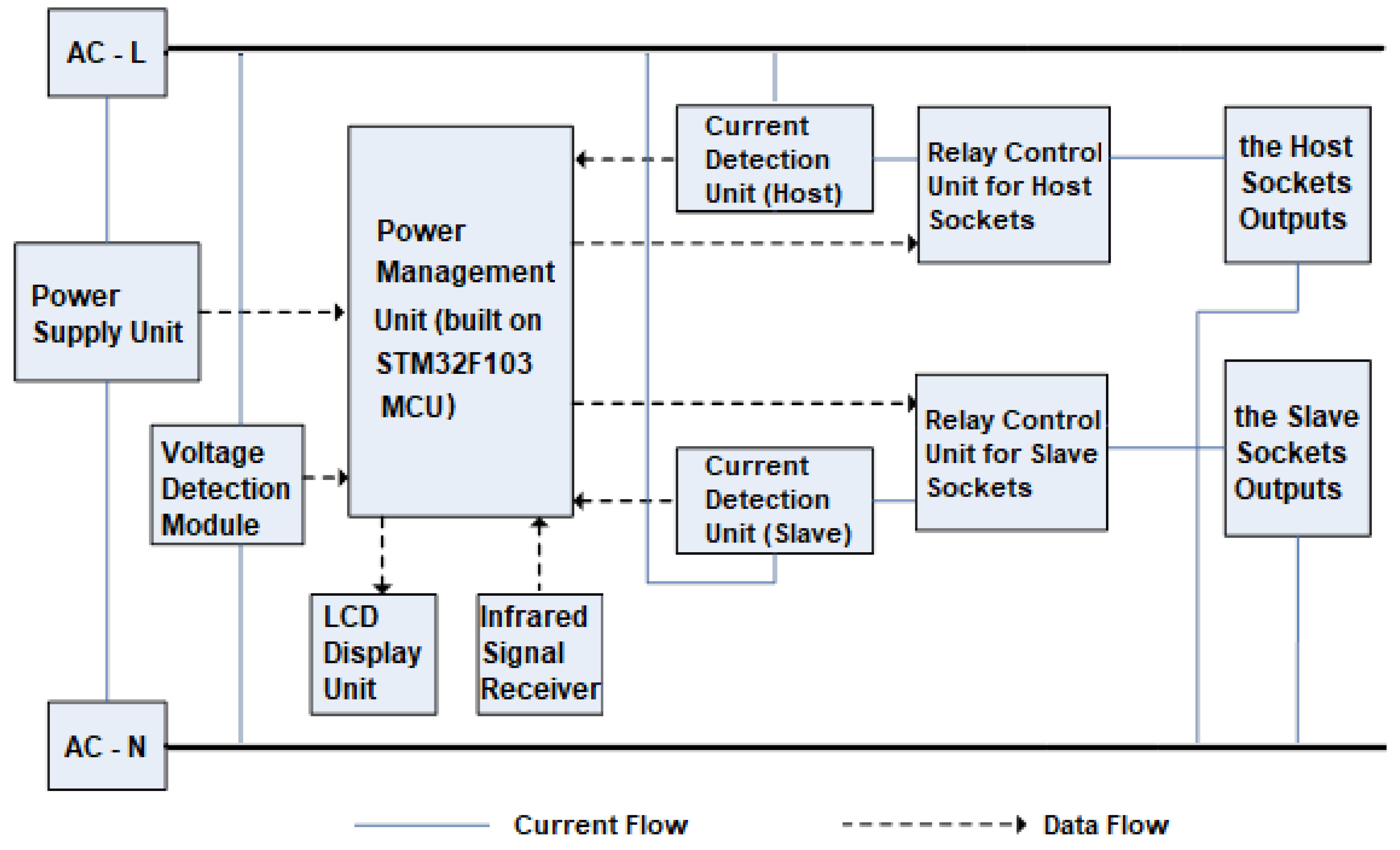
  • A host-slave mechanism was applied to the control strategy for standby energy saving. The working status (switching on or off) of auxiliary/slave devices are controlled by that of the main/host equipment. Once the embodied power management unit built on microchip STM32F103 detected sharp current dropping in host plugs, which is supposed to be a switch-off operation conducted by the occupants, it will then respond quickly to power off the smart socket for the reduction of standby energy waste.
  • The smart socket is compatible with normal remote controllers of electrical appliances, which expanded its application and allows the occupants to switch off or power on the developed smart socket conveniently with normal remote controllers.
  • The safety protection measures have been employed to avoid overvoltage, which is normally recognized to be hazardous in electricity consumption.
  • The developed smart socket system can be easily integrated into the existing household power network. Neither extra wiring nor network connection is required, which promotes the economic attractiveness of the proposed system.
  • An energy-efficient switching power module was designed to power the proposed system, which can further reduce the energy consumption of the smart socket. This allows a reduction in the standby consumption of appliance to zero secondly at a cost of only 0.8 W operational energy use.
With the characteristics mentioned above, the smart socket is a type of “off-the-shelf” product designed to reduce the standby losses of connected electrical appliances. The target end-users of this product are the dwellings with the lower home automation system integrated, but the occupants would like to improve the family energy performance without the involvement of costly high-tech intelligent systems.
To present this research in a logic way, the rest of this paper was structured as follows. Section 2 reviews the recent state-of-the-art smart sockets, and the hardware framework and software design are detailed in Section 3. Section 4 is focused on the experimental validation and discussion. After that, Section 5 presents the precision testing for measurements and error analysis, and Section 6 contains the concluding remarks of this study.

2. Literature Review

Over the decades, great efforts have been devoted to the reduction of greenhouse gas (GHG) emissions, which is commonly recognized as a major contributor to global warming and climate change [2]. As energy conservation is responsible for a considerable amount of GHG emissions, energy-efficient design and standby waste reduction become a key element in the production of customer electronics. Meanwhile, serials of policies and regulations have been issued by governments with financial support provided to encourage energy-saving design and manufacturing of customer electronics [3,4,5]. One important regulation is the ECN 1275/2008, issued by the European Commission (EC) on 6 January 2010, which clarified the standby (off mode) and standby plus (mode provides information or status display in addition to possible reactivation function) consumptions of household and office electrical appliances. According to the statement of this regulation, the standby power consumption of electronics should be less than 1 watt, while that of the standby plus should not exceed 2 watts. In addition, closing mode and/or standby mode is required as a compulsory integration of electronics. This regulation was further developed to limit the standby and standby plus consumptions to 0.5 watt and 1 watt on 6 January 2013, respectively [4].
As to the occupant’s engagement in energy saving, pioneer studies found that energy consumption monitoring and reminding would be an effective way not only for occupants’ education, but also for their behavior changes. A study conducted in Reference [6] proposed an outlets system which can be remotely controlled and monitored by the short message service of a GSM cellular phone. Reference [7] established a web-based system, which can control the on/off mode, as well as schedule the operation automatically (once a week or once a day) of power sockets through internet communications. The developed system can also calculate the power consumption and associated expenditures for the controlled power sockets. The target was to remind occupants with energy consumption details, which was then expected to encourage them into taking energy saving action. The studies in References [8,9] were focused on consumption monitoring and energy-efficient control. Reference [10] proposed a web-based energy management system, which can display the status of appliances and important event information on a touch screen, as well as realize remote control boosted by web ends. A home energy management system was presented in Reference [11]. In this system, real-time easy-to-access information about appliance energy consumption can be provided, with intelligent control strategies and optimization applied locally. Review on recent studies also indicated that demand side management (DSM) has found an effective way contributing to the energy saving at built environment. Apostolopoulos et al. presented a study of DSM in smart grid networks built on reinforcement learning [12]. Palensky and Dietrich demonstrated an outlook in DSM and smart loads with a review of current studies [13].
A great number of intelligent control systems have emerged to support the energy saving of electric appliances in recent years. One important application is the active intelligent power control system built on sensors network. In this type of system, multiple sensors were employed to locate the zones and detect the relevant activities of occupants, and microcontrollers will then the response to the power control of appliances with the received sensor data and programmed control logic. For example, an intelligent power management system was developed in Reference [14] where an automatic system integrated with light sensors and microchips was used for lighting control. In this system, all the controlled zones were equipped with light sensors, and the intelligent system would apply lighting controls based on the detecting results sent by sensors. The Reference [15] worked on the standby energy reduction of electric devices. In this study, a multiple-sensor network was also employed to monitor the energy consumption of appliances. Studies reviewed by Tsai et al. also indicated that multi-sensor systems could improve the accuracy of energy consumption prediction, but suffers from higher system cost and operational energy consumption issues [1]. In another word, the sensor-network based intelligent systems can provide high precision detection and implement accurate energy-efficient control. However, the associated energy consumption of systems was commonly underestimated or even overlooked. Therefore, with the integration of multiple sensors and required devices for the measurement of temperature, distance, position and environmental lighting, the associated energy consumption might also need to be considered to avoid improving one element at the cost of another one.
In the recent years, WIFI, ZigBee, Bluetooth technologies and Internet of Things (IoT) have also found a wide application in the development of energy-efficient control systems and smart sockets. Regarding the different communication manners, intelligent plugs based on Wi-Fi connection were discussed in the literature [16,17,18]. Reference [16] introduced the development of a smart plug built on a low-cost Wi-Fi controller composed of a microcontroller and a Wi-Fi module. Reference [17] demonstrated another Wi-Fi based intelligent socket which was built on an MSP430 microchip controller. This system can be remotely set and operate with two modes, the normal mode and a timing mode. In addition, overload, overvoltage and overcurrent protections were integrated to address safety concerns. There also some smart plugs like the OMG (Object Management Group) in Reference [18] and Wi-Fi kamkunit in Reference [19] were developed to power on/off appliances via Wi-Fi communications.
Bluetooth is another communication technology which is widely applied in smart socket development. A solution was proposed in Reference [8] to control and monitor home appliances by using a Bluetooth low energy (BLE) smart plug as a referent device. The application can be implemented on Android OS to extend its remote operation. Another power outlet system that uses Bluetooth is detailed in [20]. This study proposed a smart office energy management system which can intelligently control the power of PC, monitor, and lights through a location-aware approach based on BLE beacons, smart plugs, and a mobile app. Recently, Zigbee technology has also attracted wide attention in intelligent sockets design. In a study conducted by Han et al., a ZigBee-based energy measurement and communication unit was integrated to monitor the energy consumption of home appliances and lights [21]. Reference [22] combined Zigbee with Internet protocols to carry out both remote and on-site power on/off control and measure the current of home electrics. A similar study was conducted, in Reference [23], where end-users can easily turn on/off the home appliances by connecting the appliances to the smart plug with ZigBee communication. While Reference [24] presented the design and implementation of a ZigBee-based smart power socket system with functions, including remote control, energy consumption monitoring, overconsumption control, vampire currents detection and the avoidance of electrical fires and shocks. The IoT-based structures presented in the Reference [25] interact with the surrounding environment in terms of sensing and metering, processing this information to extract knowledge for optimizing energy efficiency at the demand side. Blanco-Novoa et al. shows the benefits and opportunities that IoT technologies can provide for the internet of energy. The combinations of WIFI, ZigBee, Bluetooth and IoT technologies have increased the intellectualization of appliances and brought more convenience to the end-users. However, intelligent products with complex functions and require more difficult operations might affect the user experience, which will correspondingly limit the application of products. In addition, those designs heavily dependent on the network environment, which might suffer from the reliability and stability of network connections. As in Reference [16], the web browsers used by occupants were required to be in the same local network with the connected devices for a reliable operation.
Smart systems based on sensor networks can provide high-precision detection, however, the operational energy consumption of integrated sensors might contribute significantly to the overall energy expenditure. The integration of WIFI, ZigBee, Bluetooth and IoT contributed significantly to the precisions of measurement and control, but at the cost of increasing the difficulty of operating and affecting user experience, especially for senior people with limited IT background. In addition, the mentioned designs rely heavily on the network environment, which might limit their application due lack of stable internet access. In light of the above, this study aims to develop an independent smart socket for the reduction of standby energy waste of residential and office electric appliances. The advantages of the proposed system might include, but not limited to no requirements on rewiring and large-scale sensors network, as well as to no need to carry out any circuit transformation. Therefore, it is a plug-in-and-use system. As only low costs and low energy consumption elements are included for system construction, the solution is affordable and energy-efficient.

3. System Development

Over the years, a growing number of studies have been conducted with the goal to develop smart and intelligent sockets. These studies, and their subsequent devices, strongly supported the reduction of standby energy waste of electric appliances. However, most of them suffer from heavy dependence on network communications, as well as complex (re)wiring and operating procedures. In this section, the hardware and control mechanism are introduced for the development of an economical easy operating smart socket.

3.1. Framework of the Hardware System

Underpinned on the functional requirements of the proposed energy-efficient smart socket, a hardware framework built on STM32F103 microchip was developed. As shown in Figure 1, the developed system is composed of a power supply unit, an infrared signal receiver, a host-slave control operator, a power management unit built on an STM32F103 microchip, a voltage and current detection module and an LCD (Liquid Crystal Display) unit. As discussed in the previous sections, power outlets on the smart socket are developed as main jacks plugged with host devices and auxiliary jacks providing power connections to slave appliances. Instructions sent by the remotes of host devices are received by the infrared signal receiver and transmitted to the power management unit with monitoring voltage and current data provided by the detection module for logic judgment. Where the power management unit takes the role of data processing and logic operation as the central processing unit (CPU) of the developed system. After that, control signals are sent to the host-slave control operator for the power control of jacks. The host-slave control operator applied in this system is composed of relay control units for both the host and slave sockets, which can response to the control signals to power on or power off the outlets on the smart socket. The LCD module was developed in this system to display the real-time monitoring values of voltage and current, as well as the power status of host devices (“on” or “off”). The power supply unit is a switching power module employed to power the smart socket system in an energy efficient manner. Circuits of the voltage and current monitoring/detecting module are detailed in the following section.

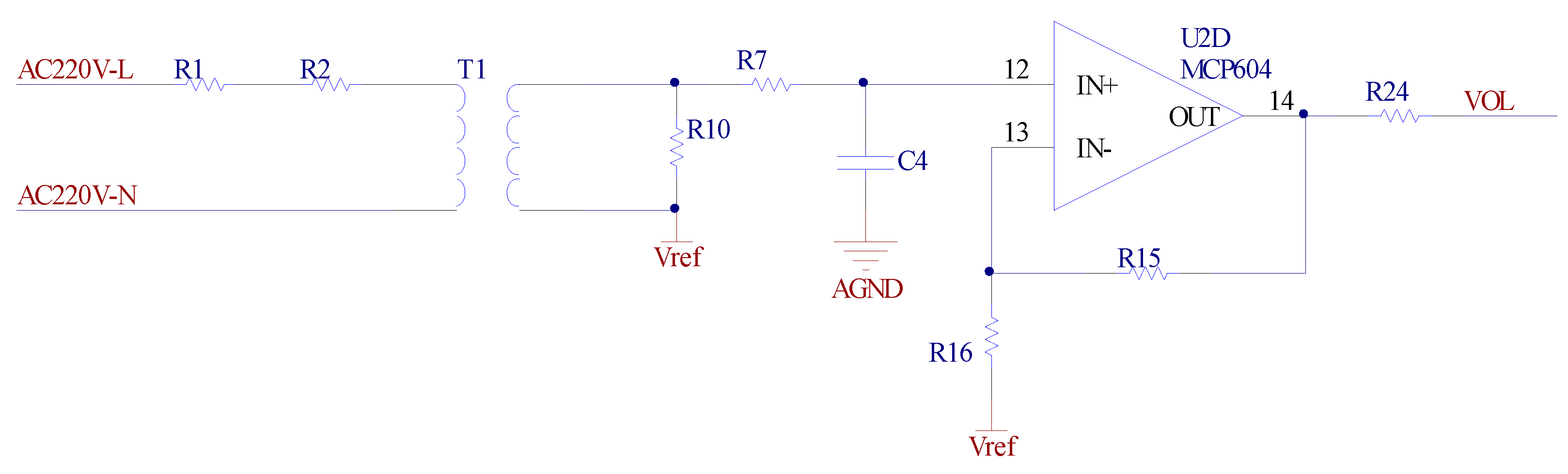
3.2. Voltage Monitoring Unit

The voltage and current detection module in this system are constructed with a voltage monitoring unit and a current monitoring unit. As shown in Figure 2, the voltage monitoring unit is built up with an AC voltage transformer supported by an operational amplifier circuit.
For the electrical isolation between the high voltage and low voltage circuits, the fluctuation of detected voltage values is transformed into current variations in the primary layer of the AC voltage transformer by integrating resistors in this circuit. After that, the current signals are transformed back into voltage values within a predefined range by employing a sensing resistor in the second layer for voltage output, which is easier for measurement. The characteristic values of the selected AC transformer, primary resistor and secondary resistor, as well as associated amplification coefficient and reference voltage are listed Table 1.
Given the proportion of input and output currents is 2 mA:2 mA for the AC voltage transformer, and the value of the primary resistor is 200   K Ω in Table 1. The current value in the primary layer is then obtained as 1.55 mA. The voltage applied on the secondary resistor R 10 is 155 mV. Therefore, the voltage output of the amplifier can be expressed as Equation (1) according to its physical characteristic.
V o = ( 1 + R 15 / R 16 ) V i ( R 15 / R 16 ) V r e f ,
where V o , V i , and V r e f are the output, input and reference voltages respectively, while R 15 and R 16 denote the resistances of resistors R 15 and R 16 . As V i is the resultant of voltages applied at the resistor R 10 and V r e f , the formulae then can be adopted as Equation (2):
V o = V R 10 ( 1 + R 15 / R 16 ) + V r e f .
Given the AC voltage of 220 V and the reference voltage of 1.25 V, the voltage output is regulated within 0.49~2.0 V, which falls in the acceptable detecting range of STM32F103 microchip. The voltage output VOL is connected to the input pin PA0 of the microchip STM32F103 in this system. A related algorithm was designed to read the voltage values of the smart socket, and then the power management unit provides overvoltage protection by cutting off the power supply if the detected voltage value is out of the predefined range.

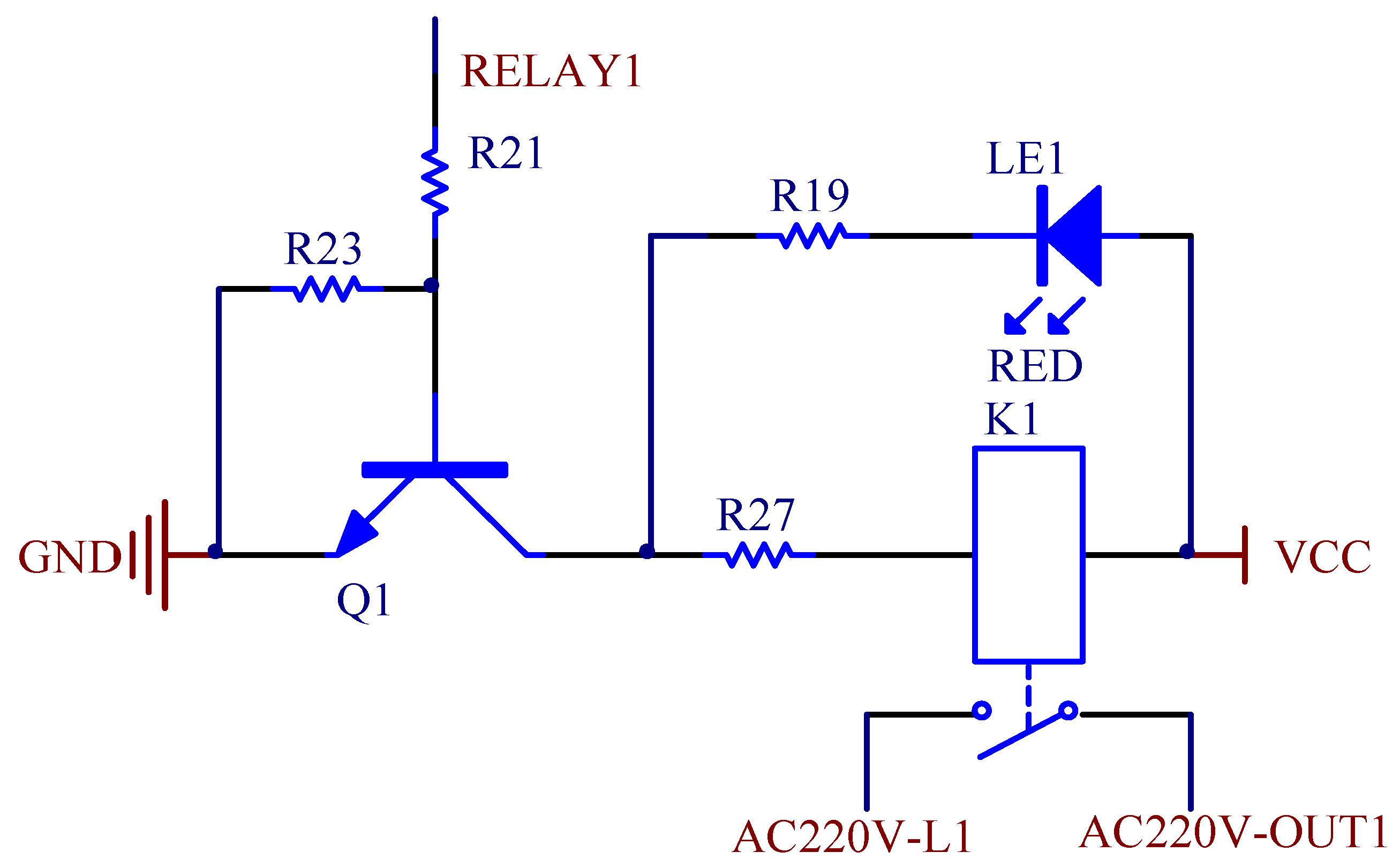
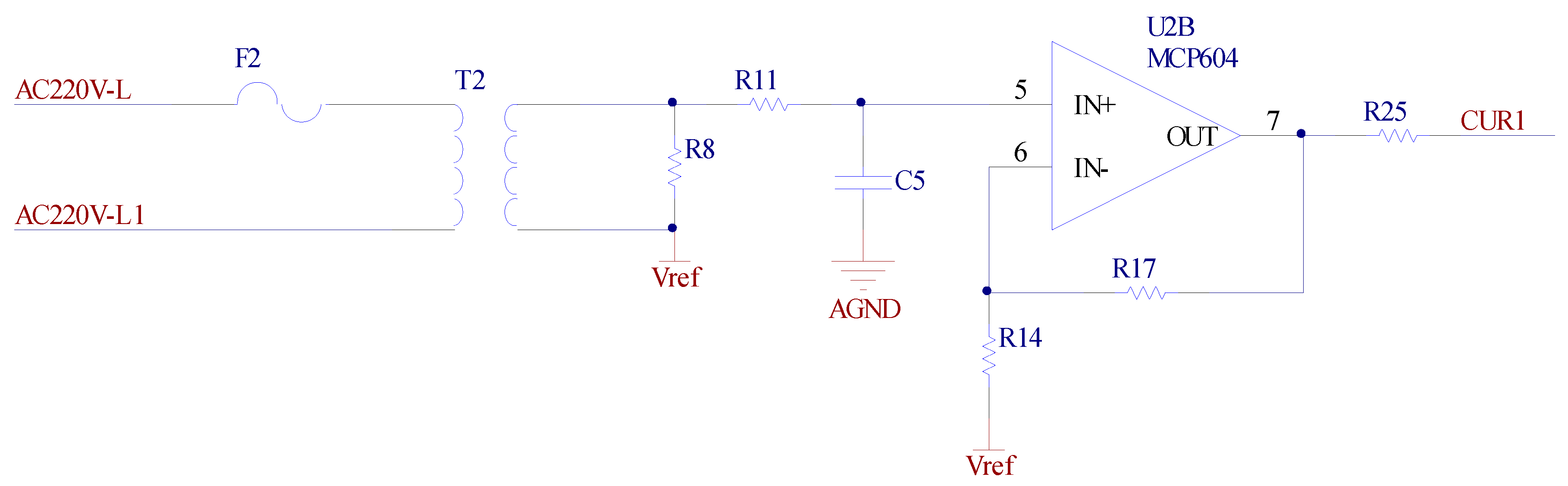
3.3. Current Monitoring Unit

Another element of the voltage and current detection module is the current monitoring unit, which is composed of a current transformer and an operational amplifier circuit. Similar to the voltage monitoring unit, electrical isolation was also applied to limit the current within an acceptable range for detecting, measurement and system protection. The developed unit can convert the 5 A current consumed by appliances into 2.5 mA for measurement proportionally. The characteristic values of the selected current transformer, primary resistor and secondary resistor, as well as associated amplification coefficient and the reference voltage are listed Table 2.
The current monitoring unit is composed of two circuits, as shown in Figure 3 and Figure 4, for the host and slave jacks respectively. Similar to the voltage monitoring circuit presented in Figure 2, the reference voltage of the operational amplifier V r e f is set as 1.25 V, and the output voltage is regulated to be positive after calibration. As the amplification coefficient was preset as 3.9, the range of the voltage output is regulated between 0.28~2.23 V in this case, which aligns with the permitted detecting range of the STM32F103 microchip. The current values of the host and slave jacks can be obtained from a proposed filtering algorithm. Then logic control of power on or off is applied by the power management module based on the obtained current values.
As shown in Figure 3 and Figure 4, the host jack is controlled by an operator built with a relay unit. The control terminal RELAY1 is connected to pin PB8 of the STM32F103 microchip. The output terminal CUR1 of the operational amplifier for the host jack was connected to the pin PA1 of the STM32F103 microchip. In this system, voltage outputs of CUR1 was processed by the microchip STM32F103, and the current value in the host jack is then identified with a filtering algorithm. After that, control signals were transmitted to the control terminals of the host operator RELAY1 to switch the host jack for energy saving. Detailed operation procedure and control logic are presented in the following section. Based on the similar methodology, current monitoring circuit of slave jacks are developed in this study for measurement and control operations.

3.4. Flowchart and System Control Operations

Given the methodology and hardware development stated in previous sections, this section is primarily focused on the control logic design and associated procedure scheduling. From the perspective of function requirement, a status flag was employed in the main program to indicate the status of the host-slave operator. Values of the status flag correspond to the following electricity supply status: 0 for both the host and slave jacks are powered off; 1 for host jacks are switched on, but slave jacks are switched off; while 2 for both the host and slave jacks are powered on. As shown in the flowchart Figure 5, the logical operations can be conducted with the following steps:
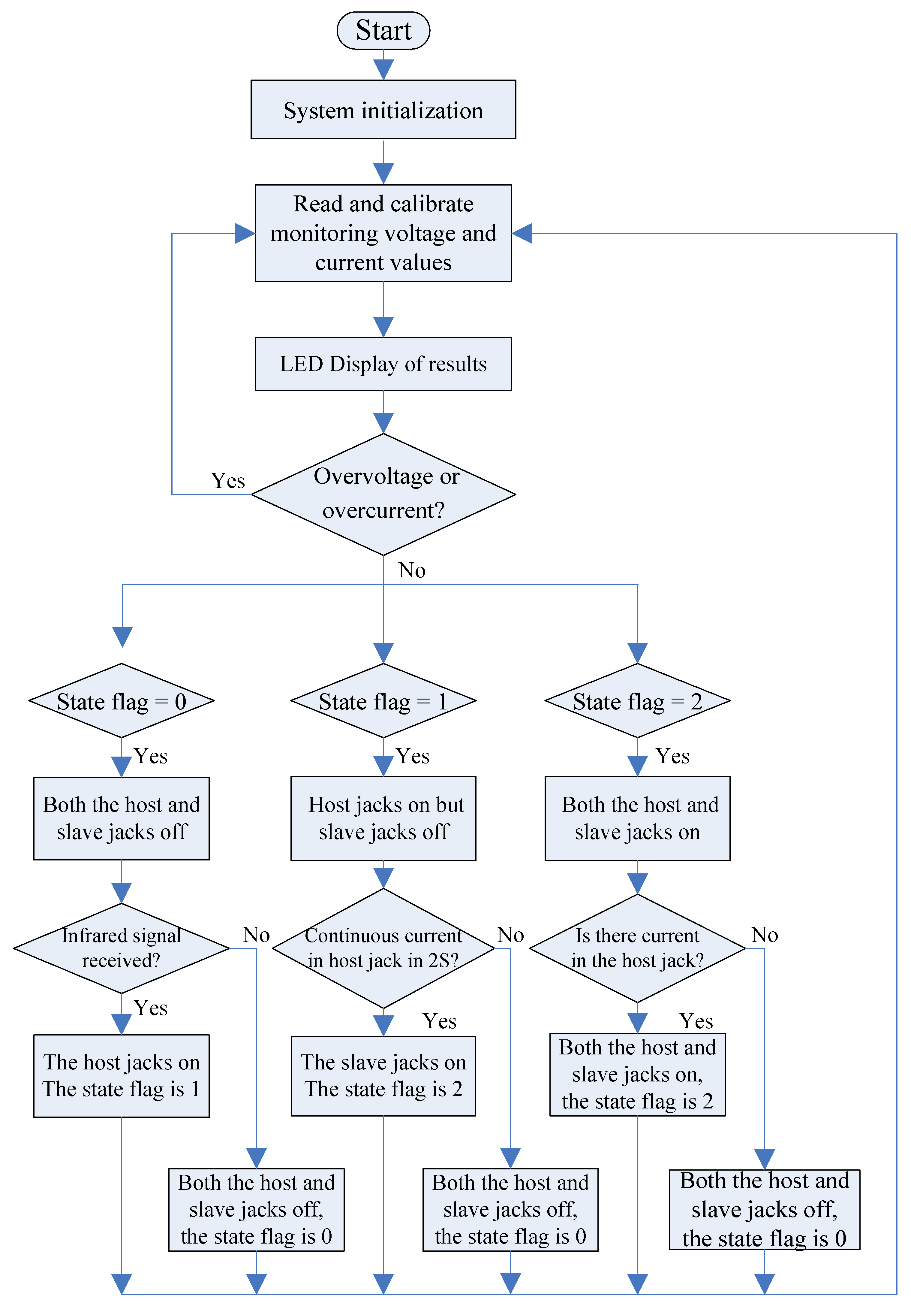
  • System initialization, the value of the flag is set as 0.
  • Read current and voltage values for the host and slave jacks, with the data then transmitted to the power management unit for processing.
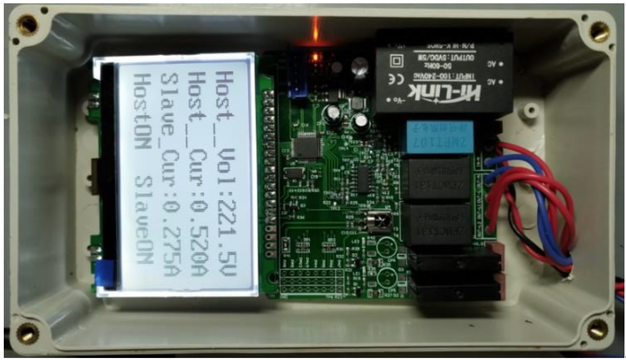
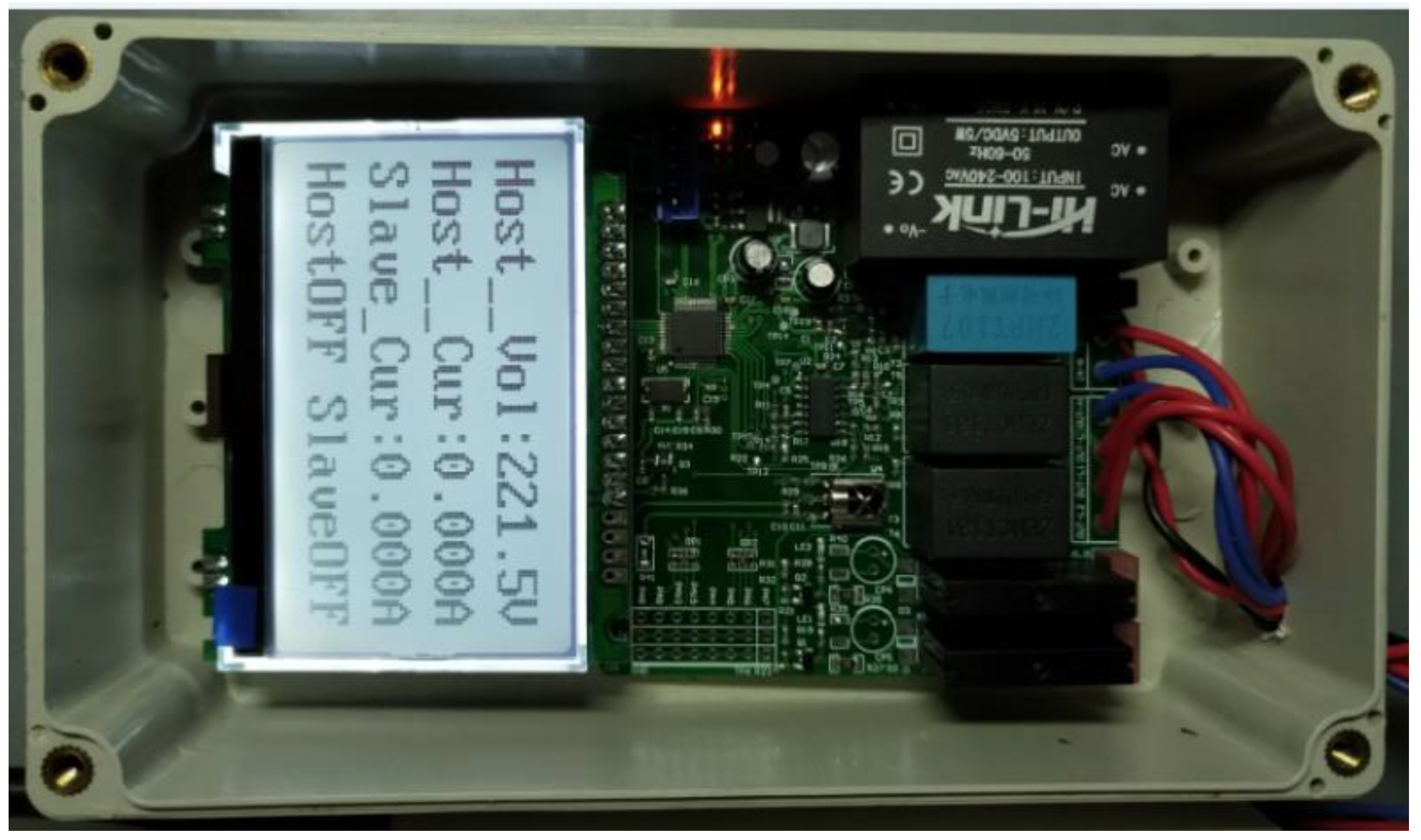
  • After processing and calibration, the values of voltage and current then can be loop displayed on the LCD module.
  • Overvoltage and overcurrent checking. Both the host and slave jacks would be powered off if either overvoltage or overcurrent was detected.
  • Logical decision making considering the flowing three scenarios: Scenario 1, the value of the status flag is 0. If infrared control instruction has been received, the host jacks then would be powered on with the flag set as 1, otherwise, both the host and slave jacks would be powered off with the flag set as 0. Scenario 2, the value of the status flag is read as 1. If the current in host jack continues within 2 s, the slave jacks would be powered on with the flag set as 2, otherwise, both the host and slave jacks would be switched off with the flag set as 0. Scenario 3, the value of the status flag equals to 2. If the host jacks are powered on, no response required, otherwise both the host and slave jacks would be switched off with the flag set as 0. The procedure for smarter control operations can then be described as:
    If (Status flag == 0)Both the host and slave jacks are offIf (Infrared signal received)The host jacks are on and the status flag is set as 1elseBoth the host and slave jacks are off; the state flag is set as 0endelse if (Status flag == 1)Host jacks are on but slave jacks are offIf (continuous current was detected in host jacks within 2 seconds)The slave jacks are on and the status flag is set as 2elseBoth the host and slave jacks are off; the status flag is set as 0endelse if (Status flag == 2)Both the host and slave jacks are onIf (current was detected in the host jacks)Both the host and slave jacks are on; the status flag is set as 2elseBoth the host and slave jacks are off; the status flag is set as 0endend

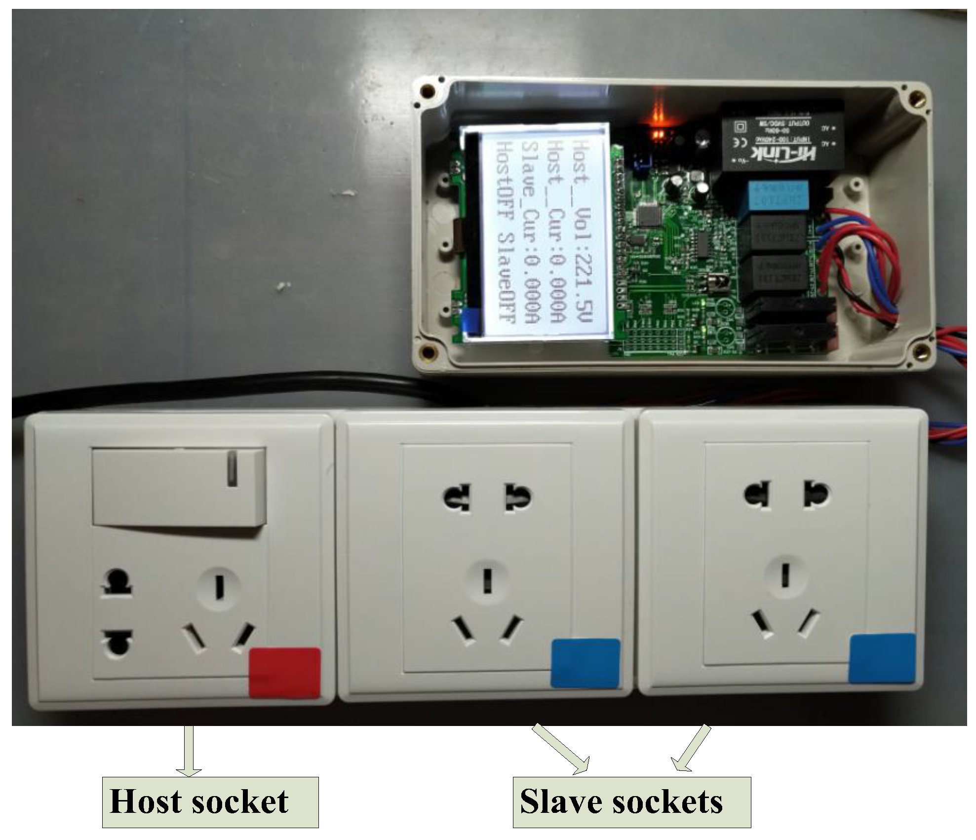
4. Experimental Validation and Discussion

A lab-scale prototype was developed in this section to validate the proposed methodology and test the functional requirements of the energy-efficient smarter socket (see Figure 6). In the experimental validation, a TV set was employed as the host device with a TV receiver box and a stereo system involved as slave appliances. In addition, to evaluate the precision of measurement conducted by the proposed system, error analysis was also included and discussed in this section.

Functional Validation and Lifecycle Assessment

Functional testing indicates that the developed system can fully satisfy the control requirements with a response delay no more than 2 s. With the switch on or wake up of the host device, slave appliances were powered on immediately, and the status “on” displayed on the LCD module. Figure 6 and Figure 7 illustrate that continues electricity supply in both the host and slave jacks is achieved with the switching on of the host device. While switch or sleeping mode of the host device results in a quick power off in slave appliances within less than 2 s’ delay, and the status “off” will be displayed on the LCD module. Figure 8 indicates that both the host and slave jacks were powered off after switching off the host device. With the host-slave control mechanism applied, standby energy reduction of electric appliances is then achieved.
To test the functional requirements and control mechanism, a scenario analysis was conducted in this research with diverse loads applied to the host and slave jacks. The functions of the smart socket were validated indirectly by measuring the current values of host and slave jacks in different scenarios. As shown in Table 3, with no load applied on the host jack in Scenarios 7–9, the current in host jack becomes zero even if there are loads applied on the slave jacks. Moreover, there is no current in slave jacks in this case. This kind of safety design can ensure the power cutting in slave jacks with the turn off of host appliances. While Scenarios 1, 2, 4, 5, and 10 indicate that continuous current in host jacks is a precondition for continuous current in slave jacks. However, in Scenarios 3 and 6, slave jacks were powered off even if there is continues current in the host jack, as no load applied on the slave jacks. In light of the above, it can be concluded that the current in slave jacks are controlled by that in host jacks, which is the fundament of standby energy reduction and safety-oriented design proposed by this research.
Targeting at the energy saving and economic attractiveness associated with the application of the developed smarter sockets, lifecycle analysis was conducted in this research, considering the embodied cost of the smarter socket and the benefits contributed by standby energy saving. Assessment context was established with the following assumptions: Commonly occupied residential appliances, including TV, TV receiver box, and stereo system were included in assessment with their operational power consumption, standby power and daily operating hours are listed in Table 4. The assessment results indicate that application of the developed smart socket can contribute to 6.40%, 77.76% and 38.76% of energy saving for TV, TV receiver box and stereo system respectively. Given the electricity tariff of 60.00 cents/kWh (which is the current market rate applied nationally in China) and the expected lifespan of 20 years for the smarter socket (identified based on the service life of major electronic components), the embodied cost of the smarter socket calculated based on the prices of the components comes to 37.00 Chinese yuan and the lifecycle costs were obtained as shown in Table 4. The assessment results indicate that an investment of 125.60 Chinese yuan (¥37.00 and ¥88.60 as the embodied and operational costs of the smarter socket respectively) might contribute to a standby cost saving up to 1725.60 Chinese yuan in an expected 20 years’ lifecycle. The payback is about 14 times to the investment. The results also show that the standby energy waste, taking 32.63% of the total energy consumption of electrical appliances, is a significant component over their lifecycle operations. On the other hand, the investment payback period was obtained as about 159 days based on the embodied and daily operational costs of the smart socket, as well as the daily standby cost saving. It then can be concluded that the developed smart socket is an economically attractive solution for standby energy and cost reduction.

5. Precision Testing and Error Analysis

Regarding the functional requirements, the voltage and current measure module play a critical role in the control logic operations. This section was developed to validate the precision of the measurement unit and identify the sources of errors. Figure 9 illustrates the results of monitoring voltage displayed on the LCD module. An adjustable AC source was employed to provide an input voltage of 178.00~251.00 V for accuracy testing. It was observed that the errors between measured and real values are less than 3.00%. Further investigation also indicates that the errors presented as a random distribution with a range of −1.05~2.85%. As there is a linear relationship between the input and output voltages shown in Equation (1), a possible explanation is that the errors are attributed to the characteristics of circuit elements. Therefore, precision improvement for the developed smart socket system could be achieved by using electronic elements with higher design and manufacturing qualities.
Current in the host and slave jacks is another important parameter for the control operations and overcurrent protection mechanism of the smart socket system. Therefore, the precision of the current monitoring unit is of great concerns. In the experimental phase, resistors of 100 Ω, 200 Ω, 500 Ω and 1000 Ω were employed as loads to validate the accuracy of current measurement in the host jacks. With a supplied AC voltage of 220 V, the real values, monitoring data and errors of current in the host jocks then can be obtained as shown in Figure 10. It was observed that the error between real value and monitoring data is up to 3.00%, with all the recorded errors fall in the interval of −1.00~3.00%. In addition, the errors are presented with a near linear distribution, which is consistent with the relativity of input–output current shown in Equation (2). These linear errors can be eliminated by applying calibrations on the raw data collected by the monitoring units.
With respect to the error analysis for current values of slave jacks, similar experiments were established in this research with loads, including 100 Ω, 200 Ω, 500 Ω and 1000 Ω resistors integrated invalidations. As shown in Figure 11, the recorded errors fall in the interval of −1.00~3.00%, and proportional to the input current in the slave jacks. Moreover, these types of near linear errors could be calibrated.

6. Concluding Remarks

Standby energy waste contributed significantly to the energy consumption of electric appliances in their operating processes. Over the years, great effort has been devoted to reducing the consumption of standby energy targeting at energy efficiency improvement and associated cost saving. The development of smart socket has been found as a desirable solution to address these concerns. However, previously reviewed literature did not find an optimal design for the development of economic easy operating smart sockets.
In this study, a smart socket system based on STM32F103 microchip was proposed with the highlights, including, but not limited to, easier control, safety design, lower embodied cost, no rewiring required and great performance in standby waste reduction. Findings of this research can be summarized as:
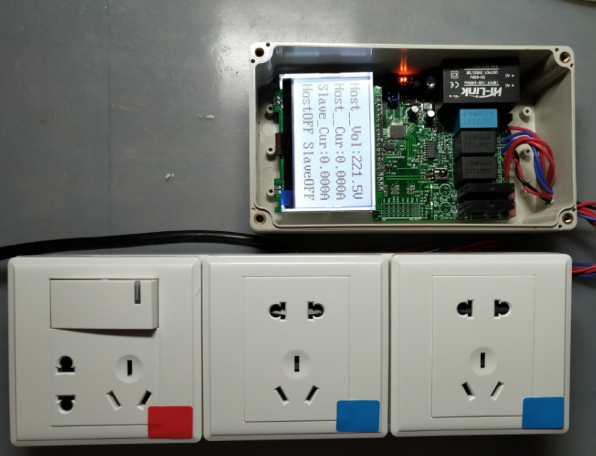
  • Experimental testing and scenario analysis indicate that the developed system can fully satisfy the functional requirements and realize the proposed host-slave control mechanism. The response delay is less than 2 s.
  • Lifecycle analysis illustrated that the integration of the developed smart socket can contribute to 6.40%, 77.76%, and 38.76% of energy saving for TV, TV receiver box and stereo system respectively. Regarding the economic concern, the assessment results indicated that an investment of 125.60 Chinese yuan on the smart socket resulting in a standby cost saving up to 1725.60 Chinese yuan over 20 years. The investment payback period is within 159 days.
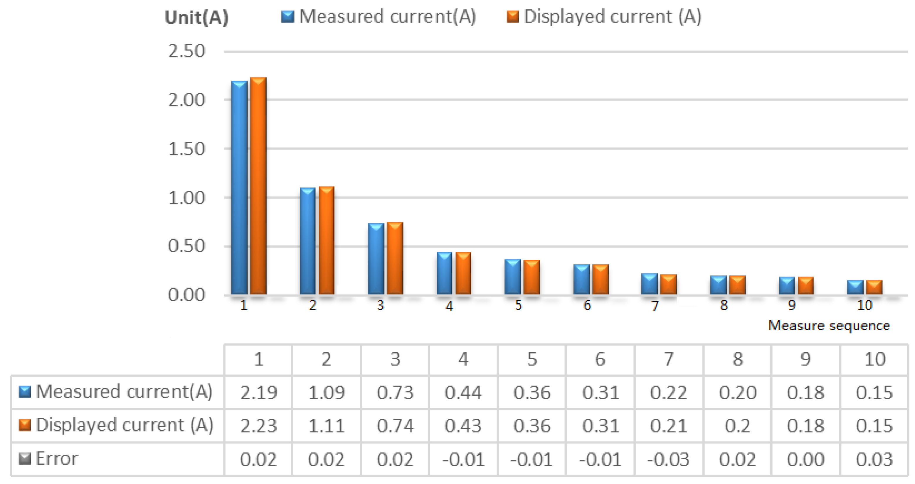
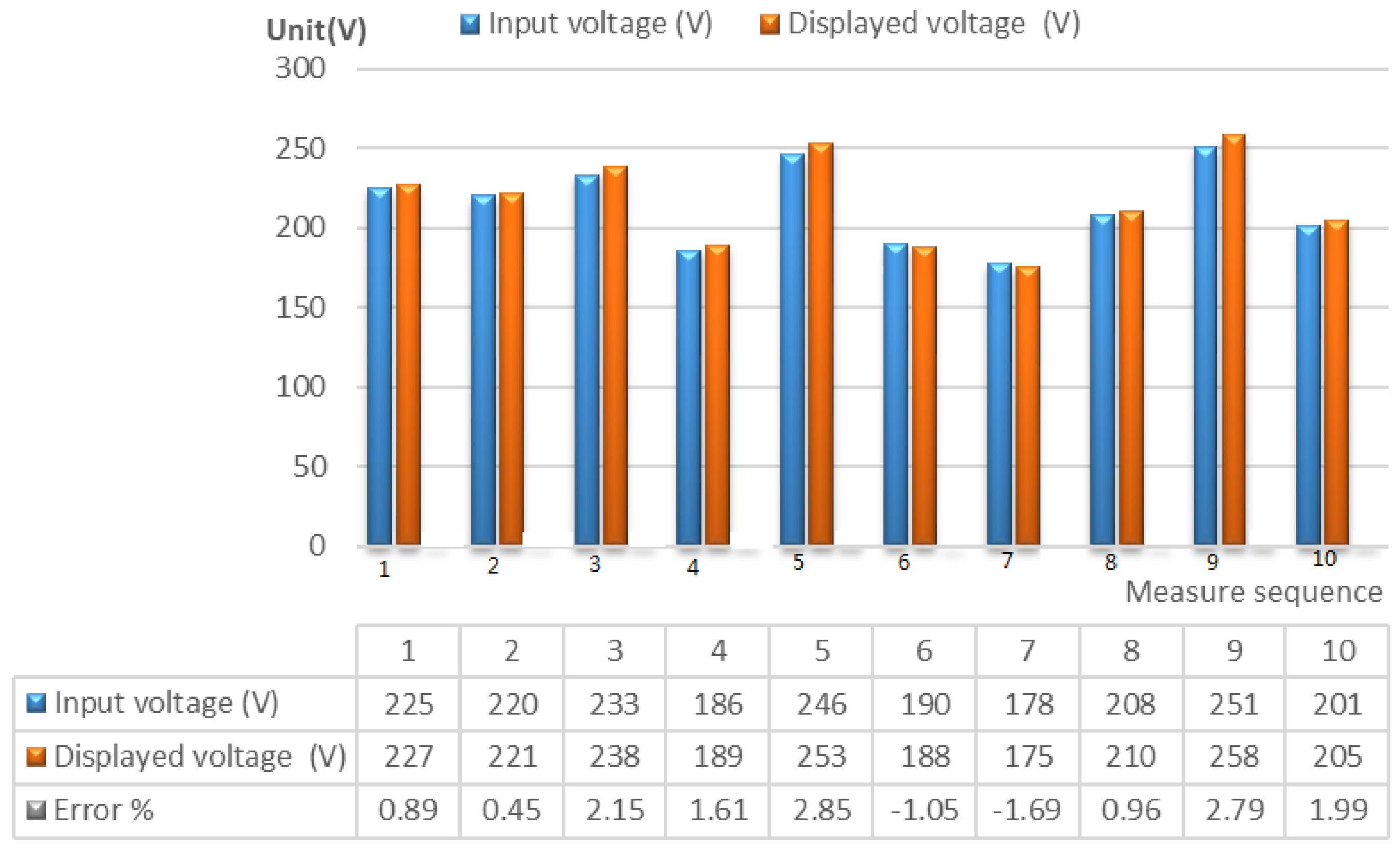
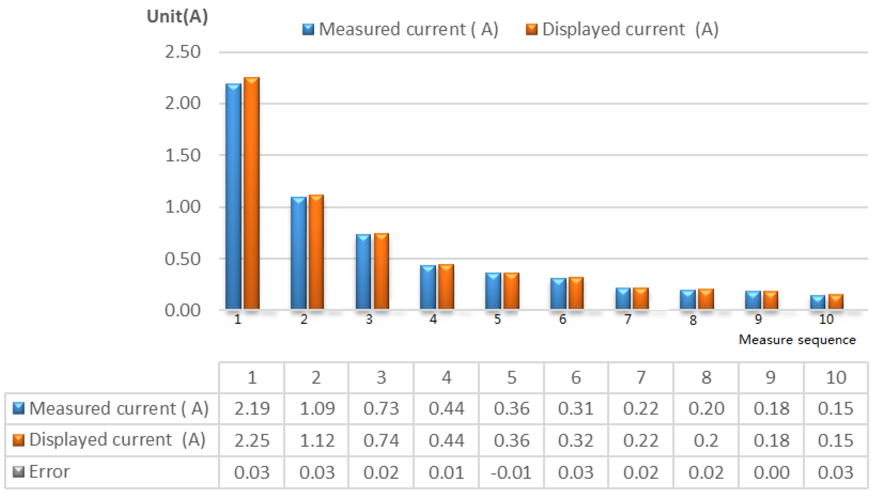
  • Precision testing and error analysis were conducted in this research to validate the reliability and stability of the designed system. Results showed that an acceptable error ratio of less than 3.00% appeared in the measurements of voltage and current values. For the monitoring voltage value, there is a random error which might result from the characteristics of electronic elements. In contrast, the errors in measured current values are proportional to the input current values.
As the fundamental parameters, monitoring voltage and current values play critical roles in control operations, as well as overvoltage and overcurrent protection. Despite the measurement errors of the current system fall within an acceptable range, it is still worth to improve the precision for higher performance system development. Future studies could be focused on precision improvement by employing higher quality electronic components and developing more accurate calibrating algorithms. Moreover, limited by the time frame, LCA was employed to evaluate the economic attractiveness with theoretical analysis established to assess the technical desirable of the developed system. Therefore, it is still worth to conduct further comparisons with existing studies targeting at optimal solutions for the standby waste reduction of electric appliances.

Author Contributions

Conceptualization and methodology, M.M. and B.H.; programming and validation, M.M.; writing—original draft preparation, M.M. and L.L.; writing—review and editing, B.H.; supervision, B.W. and J.C.

Funding

Funding that permitted this research is granted by the Education Department of Jiangsu Province for Outstanding Teaching Teams through the “Green and Blue” project and Yangzhou Polytechnic Institute.

Conflicts of Interest

The authors declare no conflict of interest.

References

  1. Tsai, K.L.; Leu, F.Y.; You, I. Residence energy control system based on wireless smart socket and IoT. IEEE Access 2016, 4, 2885–2894. [Google Scholar] [CrossRef]
  2. Tompros, S.; Mouratidis, N.; Draaijer, M.; Foglar, A.; Hrasnica, H. Enabling applicability of energy saving applications on the appliances of the home environment. IEEE Netw. 2009, 23, 8–16. [Google Scholar] [CrossRef]
  3. Executive Order–Energy Efficient Standby Power Device. Available online: https://georgewbush-whitehouse.archives.gov/news/releases/2001/07/20010731-10.html (accessed on 19 October 2018).
  4. Archived Copy. Available online: https://web.archive.org/web/20110209212259/http://www.fypower.org/news/?p=1386 (accessed on 19 October 2018).
  5. Standby and Off Leaflet. Available online: https://web.archive.org/web/20111109020207/http://www.bis.gov.uk/assets/bispartners/nmo/docs/eup/leaflets/standby-and-off-leaflet.pdf (accessed on 19 October 2018).
  6. Lien, C.H.; Bai, Y.W.; Lin, M.B. Remote-controllable power outlet system for home power management. IEEE Trans. Consum. Electron. 2007, 53, 1634–1641. [Google Scholar] [CrossRef]
  7. Lien, C.H.; Chen, H.C.; Bai, Y.W.; Lin, M.B. Power monitoring and control for electric home appliances based on power line communication. In Proceedings of the 2008 IEEE Instrumentation and Measurement Technology Conference, Victoria, BC, Canada, 12–15 May 2008; IEEE: Piscataway, NJ, USA, 2008. [Google Scholar]
  8. Horvat, I.; Lukac, N.; Pavlovic, R.; Starcevic, D. Smart plug solution based on Bluetooth low energy. In Proceedings of the 2015 IEEE 5th International Conference on Consumer Electronics, Berlin, Germany, 6–9 September 2015; IEEE: Piscataway, NJ, USA, 2015. [Google Scholar]
  9. Morsali, H.; Shekarabi, S.M.; Ardekani, K.; Khayami, H.; Fereidunian, A.; Ghassemian, M.; Lesani, H. Smart plugs for building energy management systems. In Proceedings of the Iranian Conference on Smart Grids, Tehran, Iran, 24–25 May 2012; IEEE: Piscataway, NJ, USA, 2012. [Google Scholar]
  10. Hu, Q.R.; Li, F.X. Hardware design of smart home energy management system with dynamic price response. IEEE Trans. Smart Grid 2013, 4, 1878–1887. [Google Scholar] [CrossRef]
  11. Son, Y.S.; Pulkkinen, T.; Moon, K.; Kim, C. Home energy management system based on power line communication. IEEE Trans. Consum. Electron. 2010, 56, 1380–1386. [Google Scholar] [CrossRef]
  12. Apostolopoulos, P.A.; Tsiropoulou, E.E.; Papavassiliou, S. Demand response management in smart grid networks: A two-stage game-theoretic learning-based approach. Mob. Netw. Appl. 2018, 10. [Google Scholar] [CrossRef]
  13. Palensky, P.; Dietrich, D. Demand side management: Demand response, intelligent energy systems, and smart loads. IEEE Trans. Ind. Inf. 2011, 7, 381–388. [Google Scholar] [CrossRef]
  14. Lee, M.; Uhm, Y.; Kim, Y.; Kim, G.; Park, S. Intelligent power management device with middleware based living pattern learning for power reduction. IEEE Trans. Consum. Electron. 2009, 55, 2081–2089. [Google Scholar] [CrossRef]
  15. Han, J.; Lee, H.; Park, K.R. Remote-controllable and energy-saving room architecture based on ZigBee communication. IEEE Trans. Consum. Electron. 2009, 55, 264–268. [Google Scholar] [CrossRef]
  16. Yaowaluk, T.; Wanchalerm, P. A low-cost Wi-Fi smart plug with on-off and Energy Metering functions. In Proceedings of the 2016 13th International Conference on Electrical Engineering/Electronics, Computer, Telecommunications and Information Technology (ECTI-CON), Chiang Mai, Thailand, 28 June–1 July 2016; IEEE: Piscataway, NJ, USA, 2016. [Google Scholar]
  17. Xu, A.A.; He, S.P. The wireless smart socket control system design. In Proceedings of the 2nd International Conference on Advanced Robotics and Mechatronics (ICARM), Hefei, China, 27–31 August 2017; IEEE: Piscataway, NJ, USA, 2017. [Google Scholar]
  18. Arduinoall Smart Plug Wi-Fi Kankunit Smart Plug 2015. Available online: http://www.arduinoall.com (accessed on 19 October 2018).
  19. Lazada OMG Smart Plug On/Off by 3G Wi-Fi Support an-droid&ios 2015. Available online: http://www.lazada.co.th (accessed on 19 October 2018).
  20. Choi, M.; Park, W.K.; Lee, I. Smart office energy-saving service using bluetooth low energy beacons and smart plugs. In Proceedings of the IEEE International Conference on Data Science and Data Intensive Systems, Sydney, Australia, 11–13 December 2015; IEEE: Piscataway, NJ, USA, 2015. [Google Scholar]
  21. Han, J.; Choi, C.S.; Park, W.K.; Lee, I.; Kim, S.H. Smart home energy management system including renewable energy based on ZigBee and PLC. IEEE Trans. Consum. Electron. 2014, 60, 198–202. [Google Scholar] [CrossRef]
  22. Bai, Y.W.; Hung, C.H. Remote power On/Off control and current measurement for home electric outlets based on a low-power embedded board and ZigBee communication. In Proceedings of the IEEE International Symposium on Consumer Electronics, Vilamoura, Portugal, 14–16 April 2008; IEEE: Piscataway, NJ, USA, 2008. [Google Scholar]
  23. Ahmed, M.S.; Mohamed, A.; Homod, R.Z.; Shareef, H.; Sabry, A.H.; bin Khalid, K. Smart plug prototype for monitoring electrical appliances in Home Energy Management System. In Proceedings of the IEEE Student Conference on Research and Development (SCOReD), Kuala Lumpur, Malaysia, 13–14 December 2015; IEEE: Piscataway, NJ, USA, 2015. [Google Scholar]
  24. Caramés, T.M.F. An intelligent power outlet system for the smart home of the internet of things. Int. J. Distrib. Sens. Netw. 2015, 11. [Google Scholar] [CrossRef]
  25. Blanco-Novoa, O.; Fernandez-Carames, TM.; Fraga-Lamas, P.; Castedo, L. An electricity price-aware open-source smart socket for the internet of energy. Sensors 2017, 17, 643. [Google Scholar] [CrossRef] [PubMed]
Figure 1. System framework of the intelligent power-saving socket. AC-L: Live wire of Alternating Curren AC-N: Neutral wire of Alternating Current.
Applsci 08 02276 g001
Figure 2. Voltage monitoring circuit.
Applsci 08 02276 g002
Figure 3. Current monitoring circuit for the host jacks.
Applsci 08 02276 g003
Figure 4. Host socket relay control unit.
Applsci 08 02276 g004
Figure 5. Flow chart of the program.
Applsci 08 02276 g005
Figure 6. The developed smart socket.
Applsci 08 02276 g006
Figure 7. The monitoring current values displayed on the LCD module (Power on).
Applsci 08 02276 g007
Figure 8. The monitoring current values displayed on the LCD module (Power off).
Applsci 08 02276 g008
Figure 9. Voltage outputs and errors with various AC inputs.
Applsci 08 02276 g009
Figure 10. Current outputs and errors with various AC inputs (host jacks).
Applsci 08 02276 g010
Figure 11. Current outputs and errors with various AC inputs (slave jacks).
Applsci 08 02276 g011
Table 1. Parameters of the voltage monitoring circuit.
DescriptionVoltage Transformer SpecificationsPrimary Resistors (Ω)Secondary Resistor (Ω)Amplification Coefficient (Av)Reference Voltage (V)
Parameters2 mA:2 mA100 k×21004.91.25
Table 2. Parameters of the current monitoring circuit.
DescriptionCurrent TransformerPrimary Resistor (Ω)Secondary Resistor (Ω)Amplification Coefficient (Av)Reference Voltage (V)
Parameters5 A:2.5 mA--1003.91.25
Table 3. Current values of host and slave jacks with different loading contexts.
ScenarioInput Voltage (V)Load of the Host Jack (Ω)Load of the Slave Jack (Ω)Current in the Host Jack (A) Current in the Slave Jack (A)
1220.00100.00100.002.232.25
2220.00100.00200.002.231.11
3220.00100.000.002.220.00
4220.00200.00100.001.112.23
5220.00200.00200.001.111.11
6220.00200.000.001.100.00
7220.000.00100.000.000.00
8220.000.00200.000.000.00
9220.000.000.000.000.00
10220.00500.00500.000.430.44
Table 4. Lifecycle assessment setting and results.
DescriptionOperational Power (W)Standby Power (W)Daily Operating Hours (h)Lifecycle Operational Cost (¥)Lifecycle Standby Cost (¥)
TV100.001.805.002190.00149.80
TV receiver box10.009.205.00219.00765.60
Stereo system60.0010.005.001314.00832.20
Smart socket operational1.000.805.0022.0066.60
Total operational171.0021.805.003745.001814.20
Smart socket embodied 37.00
PCB (Printed Circuit Board) 6.00
Components 14.00
Shell and Packing 5.00
Patch board 12.00

