Featured Application
The proposed formation control method has the potential to be applied in swarm robotics relevant to collaborative searching tasks.
Abstract
By forming a specific formation during motion, the robotic swarm is a good candidate for unknown region exploration applications. The members of this kind of system are generally low complexity, which limits the communication and perception capacities of the agents. How to merge to the desired formation under those constraints is essential for performing relevant tasks. In this paper, a limited visual field constrained formation control strategy inspired by flying geese coordinated motion is introduced. Usually, they flock together in a V-shape formations, which is a well-studied phenomenon in biology and bionics. This paper illustrates the proposed methods by taking the research results from the above subjects and mapping them from the swarm engineering point of view. The formation control is achieved by applying a behavior-based formation forming method with the finite state machine while considering anti-collision and obstacle avoidance. Furthermore, a cascade leader–follower structure is adopted to achieve the large-scale formations. The simulation results from several scenarios indicate the presented method is robust with high scalability and flexibility.
1. Introduction
Swarm robotics is a research field of the multi-robot system inspired by the self-organizing behavior of social animals such as birds, bees, fish, and so forth [1]. Formation control is one of the essential topics of the cooperative behavior of those systems [2]. The goal is to deploy robots regularly and repeatedly within a specific distance from each other to obtain the desired pattern, and then maintain it during movement. The members in the swarm are usually homogeneous with low complexity, only equipped with local sensing and communication devices with decentralized architecture. Swarms can be used for missions such as virgin territories exploration [3], contamination detection or tracking, and disaster search and rescue [4]. We have shown a formation-based distributed processing paradigm for collaborative searching of swarms in a scanner-like manner with a moving line formation [5]. We also extended this paradigm to more general cases not only for line formation but also for V-shaped formations [6]. In those works, the moving formations are treated as a sensor network with dynamically changing positions, so that multi-dimensional based algorithms could be applied in a distributed way. In this paper, we deal with how to get those formations under the constraints of limited visual sensing and communication abilities of each swarm member.
Formation forming problem is a well-studied problem in swarm robotics field. There are many state-of-the-art methods to deal with this problem. There are macroscopic collective behavior-inspired methods such as structured approaches (leader–follower [7], virtual structure [8]), behavior-based methods (finite state machine [9], potential fields [10], and consensus-based control [11]. In addition, multicellular mechanism-inspired formation control has also been developed, such as morphogen diffusion [12], reaction-diffusion model [13], chemotaxis [14], gene regulatory networks [15], etc. A more detailed review was published by Oh et al. [16]. However, sensors equipped in swarms are limited not only by the sensing range but also by the field of view (FOV) [17]. Under the condition of limited FOV, the connectivity of the members cannot be maintained if the omnidirectional sensing model is still applied, thus the above formation control strategies might be invalid under this constraint.
In biological research, the way geese or other big birds fly together in formations is a widely studied phenomenon [18]. Many researchers believe that those species flying in such a way can reduce the flight power demands and energy expenditure, as well as improve orientation abilities by communication within groups [19,20]. Some other works hold the different opinion that this phenomenon is constrained by the visual factors and the formations might be a by-product of the limited field of view of the following birds during flying [21]. The members of the team are communicating indirectly based on their sensed information, which means the communication is also constrained by the FOV [22]. According to Heppener’s research on flying geese [23], the visual field for each eye of a flying goose is with a binocular overlap of , as shown in Figure 1. This means the members in a swarm could only follow others in this visual field, which causes the line or V-shape formations during moving.
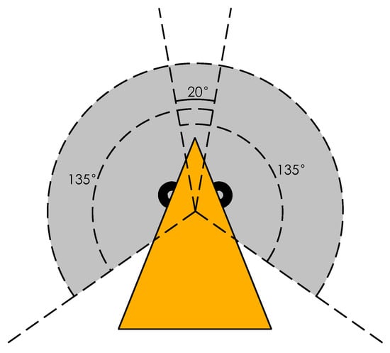
Figure 1.
Geese visual field in biological research.
This paper illustrates a formation forming control strategy inspired by flying geese. This work studies the V-shape formation forming control problem with limited visual field constraints of sensing and communication inspired by flying geese. The leader broadcasts the heading angle directly to the members in a specific range, while each member in this range also broadcasts the heading with some other simple statuses. Members in the so-called visual field limited Time-varying Characteristic Swarm (v-TVCS, which represents sub-swarms with members in the communication range of an agent) receive that information and combine it with the distances and bearing angles observed by itself to reach the motion decisions. Anti-collision and obstacle avoidance are also considered in the proposed method. The main contributions of this paper are the adoption of geese visual field constraint mechanism of formation flying. A behavior-based control strategy for line and V-shape formation forming is also presented combined with a cascade leader–follower structure.
The rest of this paper is organized as follows. In Section 2, we first state the problem of line and V-shape formation control along with the concept of v-TVCS. Section 3 introduces a modified leader–follower structure with behavior-based finite state machine design of proposed formation control strategy. Simulations under different situations are implemented to evaluate our method, and the results are given in Section 4. Section 5 is the dicussion. The conclusion is reached in Section 6.
2. Problem Statement
We suppose each member in the swarm works in the same 2-D Cartesian coordinate system with the following assumptions:
- Limited visual field: The members in the swarm only have a specific visual field in front of them; the visual angle is set to , i.e., .
- Limited perception and communication range: An agent can only communicate with members or sense others or obstacles in a certain local range (R) within the visual field.
- GPS-free: The swarm system is not equipped with GPS, i.e., no member has the global position information to perform formations.
2.1. Kinematic Model of Members
The agent in the swarm uses the following non-holonomic motion model [24], which means the agent is only able to move forward with heading changes.
where are the Cartesian position and heading of agent i, v is the linear velocity in each agent’s coordinates , and is the angular velocity. Suppose each member in the swarm is able to detect relative distances and angles of others in visual field respective to its own coordinates. and are the measured distance and angle of agent j in agent i’s sensing range. We have:
where is the visual angle constraint, . Now, for every agent in the swarm, the formation forming problem translates to finding a pose that make the agent keep the distance and bearings of the nearest neighbor, as well as the same heading angle relative to the reference agent. Furthermore, anti-collision with each other and obstacle avoidance must be considered.
2.2. Visual Field Limited Time-Varying Characteristic Swarm
Under the communication constraint, members in a swarm are not required to connect with other agents outside of some proximity, which defines the notation of communication-based neighborhood first presented by Pugh et al. [25]. The communication-based neighborhood of agent i is a set of teammates within a fixed radius R to the position of agent i, which can be written as:
where is the communication-based neighborhood; N is the number of members in the swarm; denotes agent i; and are spacial positions of i and j agents, respectively; and R is the maximum communication radius. While the swarm is moving, the neighborhoods may change over time, which causes the whole swarm to be divided into several dynamically changing sub-swarms. Xue et al. defined those sub-swarms with the concept of Time-varying Characteristic Swarm (TVCS) [26]. The TVCS of agent i at time t can be represented as follows:
where represents the TVCS of agent i. The number of members in one TVCS is obviously dynamically changing. At time t, is only able to communicate with other agents in . In our case, the perception-based communication range is also limited by the visual field of each member, thus the definition of above TVCS changes to:
where is visual field limited TVCS (v-TVCS), is the bearing angle of in ’s frame, and is the visual field of agent i. The illustration of v-TVCS is shown in Figure 2.

Figure 2.
Visual field limited Time-varying Characteristic Swarm (v-TVCS).
3. Methods
Based on some previous works [7,9,17,26], here, we employ a modified leader–follower structure combined with a behavioral finite state machine to achieve the V-shaped formation control under the constraints we assumed above.
3.1. Behavior Based Approach
Behavior-based method is one of the common choices for swarm robotics, since it is typically decentralized and can be realized with less communication compared to the others [1]. It usually defines some simple rules and actions for members in a swarm to guide them to take particular actions when conditions change; finite state machines (FSM) can realize this. For every swarm member, a finite state machine could be defined as a triple where is a finite non-empty set of states, is a finite non-empty set of inputs, and is the state-transition function set, which describes how inputs I affect states S. Since the member has some blind zone in the back, one cannot see any other member in the case of no individual in its visual field. Furthermore, the members need to fly together in V-shape formation without collision with each other or hit the obstacles. The states in S can be defined as where is searching team members, is anti-collision with other member or obstacle avoidance, and is forming the formation. is the TVCS of agent i at time t; and are the measured distance of the nearest member and the closest obstacle, respectively; and is the safe distance. The input set now can be represented as , where:
The state-transition functions could be listed as follows and are represented in Figure 3.
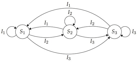
Figure 3.
Finite state machine of designed behavior based approach.
3.2. Cascade Leader–Follower Structure
The leader–follower structure is a frequently used method for formation control for groups of robots. The method, which controls the followers to keep desired distances and bearing angles to the leader, can be represented as:
where and are desired and current distances to the leader respectively; and and are the desired and current bearing angles to the leader, respectively. In our case, one cannot see the leader all the time. Consequently, instead of following the leader, we make the members form the desired formation by following a particular agent in the v-TVCS with the assistance of simple communications.
To cope with this task, the swarm leader, which defines the reference frame for the others, must first broadcast its heading direction. Other members in leader’s v-TVCS will receive this message, combine it with other state messages and then rebroadcast it in their v-TVCS again. Since we aim at building a V-shape formation, this means the leader will divide the swarm into two parts: the left part and the right part. As shown in Figure 4, the desired bearings for the two parts are different. The angle of the formatted V-shape formation is , members of the left part will keep the relative bearing angle to the leader or closest right top member with the same role of , while the right part will keep the desired bearing between the leader or closest left top member with the same role of . Because the desired bearings are different for the two parts, the messages communicated between swarm members should be the received leader’s heading, the agent’s own heading, and the role of which part it belongs. At the initial stage, if one can see the leader, it is able to determine the part role by evaluating the initial leader bearing minus the heading error with the leader. Otherwise, if the leader is not in one’s field of view, it will synchronize its role from the broadcasting of the closest member in its v-TVCS.
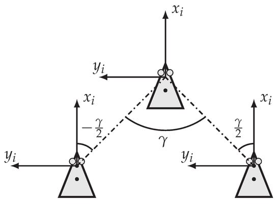
Figure 4.
Desired bearing angle of two parts.
In the case a member cannot see anyone in its visual field, it will search others by rotating with a certain forward speed with turning. Thus, the actions in can be simply defined as:
where and are random forward speed and turn speed, respectively.
Figure 5 shows the relationship with leader and follower. According to Equation (1), the kinematic equations for follower i are established:
where is the heading error with the leader, . On the other hand, according to the feedback control law, we have:
where and are feedback coefficients.
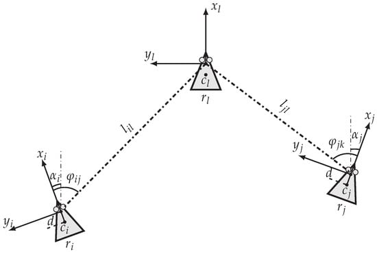
Figure 5.
Configurations of swarm members.
3.3. Anti-Collision and Obstacle Avoidance
Anti-collision and obstacle avoidance is essential for task implementation. It ensures the agents avoid hitting others in the swarm or obstacles in the environment. With the low-complexity swarm in mind, here we use a simplified Vector Field Histogram (VFH) algorithm to achieve this goal. VFH algorithm determines the movement direction by constructing vector field histogram to represent polar obstacle density (POD). First, it divides sensing field of an agent into n sectors and each sector’s cover angle is . Then, the following equation is used to calculate the corresponding POD in the histogram for each sector [27]:
where is the polar obstacle density in sector k, is the probability a point is occupied by an obstacle, is the distance from the center of the agent to point , is the maximum detection range of the sensor, and the dominion of integration is defined as
By applying a threshold to the polar histogram, a set of candidate directions that are closest to the target direction can be obtained. In the next step, the strategy to choose a direction of this set depends on the relationships between the selected sectors and the target sector. It has been proven that this method is effective for obstacle avoidance of mobile robots. In our case, since the simple swarm members need to keep the formation during moving, we have to consider the low computational complexity as well as the velocity constraints. By adopting the fundamental principle of VHF algorithm, we can design our actions in state for anti-collision and obstacle avoidance as follows.
As shown in Figure 6, it is assumed that the robot can detect the ranges in sectors () in its visual field, i.e., to , where is the heading direction of an agent. By considering the effects of neighbor sectors, the smoothed polar obstacle density on kth direction can be represented as:
where l is a positive number that represents the compute window of each direction , is the distance from the center of the agent to the obstacle in direction , is the predefined safe distance, and is the weight of the corresponding neighbor directions, which can be determined by:
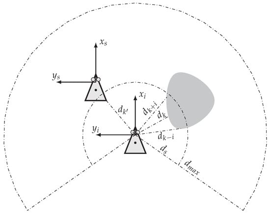
Figure 6.
Sensing sectors with obstacles.
This choice of ensures that the farther the neighbor direction from k is, the smaller the weight is as well as that the current heading direction k has the largest one.
Consequently, denote as the potential direction(s); we can choose the solution direction by:
where is the solution direction, and is a direction that contains a target determined by formation control strategy. Furthermore, the safe distance is related to the turning radius at maximum speed and the update cycle T of the agent, i.e.,
where is the safety coefficient. We can use the following equations to determine the final inputs for anti-collision and obstacle avoidance.
where is the minimal ranges to the obstacles and is the angular resolution of the ranger sensor, i.e., the width of each sector.
3.4. Proposed Formation Control Algorithm
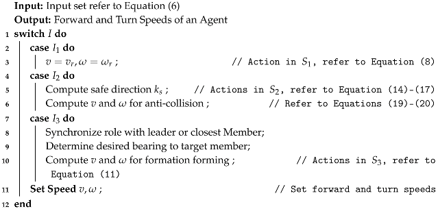
In summary, the computation procedure of each member in the proposed method is as shown in Algorithm 1. The programs are identical for each member, which ensures the high scalability of the system. The agent detects the neighbor members and obstacles, and uses the transfer functions to switch to corresponding actions described above. The complexity of the algorithm is , which is equivalent to most state-of-the-art strategies.
| Algorithm 1: Cascade leader–follower formation control with limited field of view |
 |
4. Results
We evaluated the proposed method using simulations in the stage simulator [28]. We studied the proposed method under the condition of obstacle avoidance, formation with turns, and large populations. The safe distance is set to 5 m while the desired distance is set to m, the desired formation angle is set to , and the target forward speed of the swarm leader is set to 1 m/s. Figure 7 shows the configuration of each member. The large sector with field of view is its communication range. The agent is able to exchange simple data to others in this area. This radius is set to 30 m for simulations with swarms of fewer than 50 members, and 100 m for larger swarms (N = 200). The small sector is the coverage of nine ranger sensors with FOV spread on the with some overlaps for anti-collision and obstacle avoidance. With those configurations, the simulation process and other details are given in following subsections.

Figure 7.
Member configurations in stage simulator.
4.1. Formation Control with Obstacle Avoidance
As mentioned above, the anti-collision strategy of the proposed method includes keep away from each other and obstacle avoidance. Anti-collision is considered for all simulations. The experiment in this section aims to test the strategy in an environment with obstacles. Initially, we put seven swarm members in the bottom part of a 100 m × 200 m environment, with random position and headings. The target direction of the swarm leader is set to the north. Some obstacles are placed on the way to the north, as shown in Figure 8a. The sector around the agent indicates the visual field of each member. Figure 8b shows the swarm leader starts to move to the north, and the other members are adjusting their positions and headings according to the proposed strategy. Each member chooses the corresponding target leader to achieve the cascaded leader–follower structure, and calculates control inputs according to predefined and , as shown in Figure 8c. Figure 8d shows that the formation is formed at around s.

Figure 8.
Formation before encounter obstacles.
When the moving formation encounters obstacles, as shown in Figure 9a,b, the members adjust their forward and turning speeds to obey the defined anti-collision rules to avoid obstacles. Meanwhile, they also keep away from each other during the adjustments. When they pass the barrier region, they start to reform the shape, as shown in Figure 9c. The formation is reshaped at 2 min 6.6 s, as shown in Figure 9d. The trajectories of this simulation are shown in Figure 10. In the figure, we can see the adjustments of the anti-collision movements of each members.
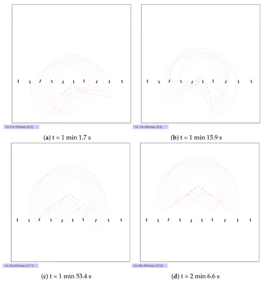
Figure 9.
Formation after encounter obstacles.

Figure 10.
The trajectories of member movements.
4.2. Flexibility Evaluation
In many searching tasks, the entire swarm may need to do more maneuvers than just moving in one direction. Members in a swarm are required to follow the leader’s trajectory change after forming the formation. We test this problem in a swarm with 31 members (1 swarm leader and 30 other members). The swarm leader is set to make a left turn at the position of with the turning speed of 0.1 rad/s. The simulation results are as shown in Figure 11 and Figure 12.
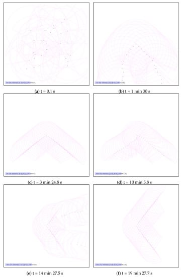
Figure 11.
Formation with turns.
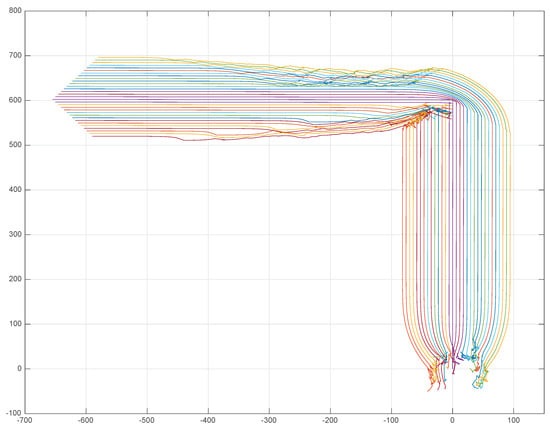
Figure 12.
The trajectories of member movements.
Initially, we put the leader at point , and the other 30 members are distributed in a certain range m around the leader with random positions and headings. Figure 11a shows the initial status of this simulation. After the swarm leader starts to move, the whole group forms the desired V-shape (Figure 11b), and the formation is formed at 3 min 24.8 s (Figure 11c). The formed shape continues to move forward until the swarm leader begins to turn, as indicated in Figure 11d. The swarm then reshapes after the disorder caused by the turn, as shown in Figure 11e. We can see in Figure 11f that the formation reformed at 19 min 27.7 s. The trajectories of this process are shown in Figure 12.
4.3. Large Swarm
One of the distinguishing characteristics of swarm robotics compared to the traditional multi-robot system is low-complexity with robust organization rules, which can be realized in large-scale applications. To evaluate our proposed method in a large swarm, in stage, we use a population of 201 (1 leader and 200 members) for the formation forming test. Similar to the flexibility evaluation, we put the leader at position , and the other 200 members are distributed in the range of m around the leader with random positions and headings, as shown in Figure 13a. The sensing radius is set to 100 m to avoid possible disconnections between different sub-swarms. The target direction of the leader is set to the north with anti-collision, i.e., the swarm leader keeps away from the others, as shown in Figure 13b. After the leader moves be the north most member of the swarm, the remaining simulation processes are shown in Figure 13c–f. It can be seen that the proposed method can form the formation under the condition of large populations of swarm members. The trajectories for this simulation is given in Figure 14.

Figure 13.
Large-scale formation control simulation.

Figure 14.
The trajectories of member movements.
4.4. Statistical Results
We tested the above simulations under each condition several times to get the statistical results. In particular, for the large-scale formation problem, we set a different sensing radius to get the impact of this parameter. As shown in Table 1, the success rates with seven agents in the environment with obstacles and 31 agents in an open environment are both 100%. The sensing radius of those situations is all set to 30 m. For the large-scale test, we set this value to 30 m, 50 m, 70 m and 100 m. The corresponding success rates are , , and , respectively. The sensing radius obviously affects the results of large-scale simulations.

Table 1.
Statistical results of the proposed method.
5. Discussion
It can be seen from the listed results above that the presented formation forming strategy for robotic swarms is proven to be effective with different populations. The following subsections are some more considerations worth discussing.
5.1. The Local Minimal
Formation control strategies with obstacle avoidance often suffer from local minima problems. They are usually caused by the conflicts between the formation control inputs and the anti-collision calculations. In Figure 10, the traces of the last two agents have vibration near the position of , which indicates those two agents have the risk of falling into the local optimum. Fortunately, According to Equation (8), our strategy for formation control has random inputs in the state of . Furthermore, we only calculate nine directions of range sensors for anti-collision. These two points ensure our method can jump out from the risk. Figure 8c indicates the right two members have some delay in reforming the formation due to the time consumed by getting out of the trouble; however, they can still catch up to move with the formation.
5.2. Unbalanced Formations
Since we do not assign the roles for each member before the task, each member gets its role during the simulation. The final results might be unbalanced V-shaped formations, which will affect the coverage of the swarm. As shown in Figure 13f, the number of agents on the left-hand side is never equal to the number on the right-hand side. When this kind of swarm formation is used in some spatially relevant tasks, the coverage area differences should be carefully considered. We also mentioned this issue in one of our previous works, which utilized unbalanced formations for collaborative target searching tasks [6].
5.3. Robustness and Scalability
Robustness and scalability are typical characteristics of swarm systems. Robustness means the system could operate normally in the case of disturbance or individual failure. Since the designed system is fully distributed with high redundancy, some members failing will be compensated by others. The distributed scheme also resists disturbance from surroundings.
Scalability is another essential property of swarm robotics, which implies the system has the ability to work under arbitrary populations. As shown in the simulations with different populations and circumstances, the proposed method is identical for every member of the swarm, so it has high robustness and scalability.
6. Conclusions
This paper introduces a flying geese-inspired V-shaped formation control strategy, which is constrained by the limited field of view. A behavior-based method combined with a cascade leader–follower structure is adapted to get the desired formation. The anti-collision issue including keep away from other members and obstacle avoidance is also achieved with a simplified polar vector field histogram method. Comparing with other methods, we have shown the introduced method is able to form the formations under the condition of the field-of-view constrained sensing and communication. Furthermore, the proposed strategy is fully distributed with robustness and scalability, which has the potential to be utilized in large-scale swarms. Although we have verified the effectiveness of the method through simulation, utilizing it in physical system still has challenges, such as the sensor based communication protocols, the kinematics of different types of robots and so forth. The future work of our research will be focused on implementing the method to physical swarm systems such as mobile robots, UAVs and underwater vehicles.
Author Contributions
Conceptualization, J.Y. and P.B.; Methodology, J.Y.; Software, J.Y.; Validation, X.W., P.B. and J.Y.; Investigation, J.Y., X.W. and P.B.; Resources, X.W.; Data Curation, J.Y.; Writing—Original Draft Preparation, J.Y.; Writing—Review and Editing, P.B.; Visualization, J.Y.; Supervision, X.W.; Project Administration, X.W.; and Funding Acquisition, X.W.
Funding
This research was funded by Shenzhen Science and Technology Innovation Commission grant number JCYJ20170413110656460 and JCYJ20150403161923545.
Conflicts of Interest
The authors declare no conflict of interest.
References
- Brambilla, M.; Ferrante, E.; Birattari, M.; Dorigo, M. Swarm robotics: A review from the swarm engineering perspective. Swarm Intell. 2013, 7, 1–41. [Google Scholar] [CrossRef]
- Trianni, V.; Campo, A. Fundamental collective behaviors in swarm robotics. In Springer Handbook of Computational Intelligence; Springer: Berlin/Heidelberg, Germany, 2015; pp. 1377–1394. [Google Scholar]
- Taraglio, S.; Fratichini, F. Swarm underwater acoustic 3D localization: Kalman vs Monte Carlo. Int. J. Adv. Robot. Syst. 2015, 12, 102. [Google Scholar] [CrossRef]
- Scheutz, M.; Bauer, P. Ultra-low complexity control mechanisms for sensor networks and robotic swarms. Int. J. New Comput. Archit. Appl. 2013, 3, 86–119. [Google Scholar]
- Yang, J.; Wang, X.; Bauer, P. Formation forming based low-complexity swarms with distributed processing for decision making and resource allocation. In Proceedings of the 2016 14th International Conference on Control, Automation, Robotics and Vision (ICARCV), Phuket, Thailand, 13–15 November 2016; pp. 1–6. [Google Scholar]
- Yang, J.; Wang, X.; Bauer, P. Line and V-Shape Formation Based Distributed Processing for Robotic Swarms. Sensors 2018, 18, 2543. [Google Scholar] [CrossRef] [PubMed]
- Panagou, D.; Kumar, V. Cooperative visibility maintenance for leader–follower formations in obstacle environments. IEEE Trans. Robot. 2014, 30, 831–844. [Google Scholar] [CrossRef]
- Askari, A.; Mortazavi, M.; Talebi, H. UAV formation control via the virtual structure approach. J. Aerosp. Eng. 2013, 28, 04014047. [Google Scholar] [CrossRef]
- Balch, T.; Arkin, R.C. Behavior-based formation control for multirobot teams. IEEE Trans. Robot. Autom. 1998, 14, 926–939. [Google Scholar] [CrossRef]
- Spears, W.M.; Spears, D.F. Physicomimetics: Physics-Based Swarm Intelligence; Springer Science & Business Media: Cham, Switzerland, 2012. [Google Scholar]
- Tanner, H.G.; Jadbabaie, A.; Pappas, G.J. Flocking in teams of nonholonomic agents. In Cooperative Control; Springer: Cham, Switzerland, 2005; pp. 229–239. [Google Scholar]
- Foty, R.A.; Steinberg, M.S. The differential adhesion hypothesis: A direct evaluation. Dev. Biol. 2005, 278, 255–263. [Google Scholar] [CrossRef] [PubMed]
- Meinhardt, H.; Gierer, A. Pattern formation by local self-activation and lateral inhibition. Bioessays 2000, 22, 753–760. [Google Scholar] [CrossRef]
- Bai, L.; Eyiyurekli, M.; Lelkes, P.I.; Breen, D.E. Self-organized sorting of heterotypic agents via a chemotaxis paradigm. Sci. Comput. Program. 2013, 78, 594–611. [Google Scholar] [CrossRef]
- Oh, H.; Jin, Y. Evolving hierarchical gene regulatory networks for morphogenetic pattern formation of swarm robots. In Proceedings of the 2014 IEEE Congress on Evolutionary Computation (CEC), Beijing, China, 6–11 July 2014; pp. 776–783. [Google Scholar]
- Oh, H.; Shirazi, A.R.; Sun, C.; Jin, Y. Bio-inspired self-organising multi-robot pattern formation: A review. Robot. Auton. Syst. 2017, 91, 83–100. [Google Scholar] [CrossRef]
- Maeda, R.; Endo, T.; Matsuno, F. Decentralized navigation for heterogeneous swarm robots with limited field of view. IEEE Robot. Autom. Lett. 2017, 2, 904–911. [Google Scholar] [CrossRef]
- Pennycuick, C.J. The Flight of Birds and Other Animals. Aerospace 2015, 2, 505–523. [Google Scholar] [CrossRef]
- Weimerskirch, H.; Martin, J.; Clerquin, Y.; Alexandre, P.; Jiraskova, S. Energy saving in flight formation. Nature 2001, 413, 697–698. [Google Scholar] [CrossRef] [PubMed]
- Galler, S.R.; Schmidt-Koenig, K.; Jacob, G.J.; Belleville, R.E. Animal Orientation and Navigation. NASA SP-262; NASA Special Publication: Washington, DC, USA, 1972.
- Bajec, I.L.; Heppner, F.H. Organized flight in birds. Anim. Behav. 2009, 78, 777–789. [Google Scholar] [CrossRef]
- Strandburg-Peshkin, A.; Twomey, C.R.; Bode, N.W.; Kao, A.B.; Katz, Y.; Ioannou, C.C.; Rosenthal, S.B.; Torney, C.J.; Wu, H.S.; Levin, S.A.; et al. Visual sensory networks and effective information transfer in animal groups. Curr. Biol. 2013, 23, R709–R711. [Google Scholar] [CrossRef] [PubMed]
- Heppner, F.H.; Convissar, J.L.; Moonan, D.E., Jr.; Anderson, J.G. Visual angle and formation flight in Canada Geese (Branta canadensis). Auk 1985, 102, 195–198. [Google Scholar] [CrossRef]
- Qu, Z. Cooperative Control of Dynamical Systems: Applications To Autonomous Vehicles; Springer Science & Business Media: London, UK, 2009. [Google Scholar]
- Pugh, J.; Martinoli, A. Multi-robot learning with particle swarm optimization. In Proceedings of the Fifth International Joint Conference on Autonomous Agents and Multiagent Systems, Hakodate, Japan, 8–12 May 2006; pp. 441–448. [Google Scholar]
- Xue, S.; Zhang, J.; Zeng, J. Parallel asynchronous control strategy for target search with swarm robots. Int. J. Bio-Inspired Comput. 2009, 1, 151–163. [Google Scholar] [CrossRef]
- Siciliano, B.; Khatib, O. Springer Handbook of Robotics; Springer: Berlin/Heidelberg, Germany, 2016. [Google Scholar]
- Vaughan, R. Massively multi-robot simulation in stage. Swarm Intell. 2008, 2, 189–208. [Google Scholar] [CrossRef]
© 2018 by the authors. Licensee MDPI, Basel, Switzerland. This article is an open access article distributed under the terms and conditions of the Creative Commons Attribution (CC BY) license (http://creativecommons.org/licenses/by/4.0/).