Featured Application
Tire model is suitable for vehicle dynamics simulation and tire design.
Abstract
This paper investigates the planar vibration characteristic of heavy load radial tires with a large flat ratio. A proposed tire model with a flexible ring on an elastic continuous foundation is investigated utilizing kinematic modeling and experimental modal analysis. Planar coupling deformation of the radial and tangential direction is considered to enrich the kinematic characteristic of the flexible belt and the continuous sidewall; a flexible ring on an elastic continuous foundation tire model is proposed to investigate the coupling vibration characteristic between the flexible belt and the continuous sidewall. In-extensibility assumption is utilized to simplify the proposed tire model and the planar vibration modal features of the heavy load radial tire are discussed. The variation of the inflation pressure on the radial and tangential stiffness of the sidewall spring model is enriched into the flexible ring on an elastic continuous foundation tire model to extend the modal prediction of the tires with a different inflation pressure. Taking the relative error between the experimental and analytical modal resonance frequency of the tested tire with a different inflation pressure as the object value, structural parameters of the proposed tire model are identified by a backward genetic algorithm. Experimental and theoretical results show that: the planar coupling vibration characteristic of the heavy load radial tire can be predicted precisely with the flexible ring on an elastic continuous foundation tire model; meanwhile, considering the linear variations of the radial and tangential sidewall stiffness due to the inflation pressure, the proposed tire model can be extended to analyze the vibration characteristic of the heavy load radial tire with a different inflation pressure.
1. Introduction
The challenges to engineer a vehicle with the smooth-riding [1], pleasant-sounding [2], and safe-maneuverability [3] characteristics are becoming increasingly difficult and emergently needed. Moreover, the assessments of the vehicle quality and comfort are greatly influenced by their expectations and perceptions of the vehicle Noise Vibration and Harness (NVH) [4], especially for the heavy load vehicle [5] at higher speed. Regarding the vehicle dynamics, the dynamic behavior of the tires is of utmost importance as the tires generating most of the external forces and moments acting on a vehicle for acceleration, steering, and braking conditions. Being the only element of the vehicle contacting with the road, the tire is a key factor regarding the force and vibration generation and transmission. Meanwhile, the accurate prediction of the tire dynamics and the ground-tire interaction [6] have always been of interest. Different tire models with the different model complexity levels have been developed and researched for different applications.
Simplified tire models with an analytical expression or purely empirically/semi-empirical formulae, such as the magic model [7], brush model [8], and LuGre model [9], etc., are used to investigate the longitudinal and lateral dynamics of the tire-road interactions with the computationally effective feature, while the structural elasticity and the flexible deformation of the tire belt and tire sidewall are ignored, leading to the existing deviation under certain manoeuvres. At the other extreme, taking the advantage the powerful computation and the composite characteristic [10], detailed tire models, such as the finite element tire model [6], absolute nodal coordinate formulation (ANCF) finite element tire model [11], and spectral element tire model [12], present the detail material feature and geometrical feature at the expense of much computation resource. Additionally, the detailed tire/road contacting feature can be investigated with the detailed tire and road model, while the large computation resource, the extensive finite element analysis (FEA)-oriented pre-processing, and the difficultly-obtained material parameters limit the extended application for vehicle dynamics.
With less computation resources required than the detailed tire model, and a higher precision than the simplified tire model, the mechanical structure-based tire model [13] is proposed and much research has been devoted to focus on the kinematic modeling and numerical solving. Being the typical tire model respective of the mechanical structure-based tire model, the flexible belt tire model simplifies the tire as the flexible belt on an elastic foundation (referred to as the tire sidewall) and can range from one dimension to three dimensions. The circumference vibration of the flexible belts can be featured as the one-dimensional tire model [14] (referred to as the radial deformation in the polar coordinate system), or the two-dimensional tire model [15] (referred to as the radial and tangential deformation in the polar coordinate system), while the cross-section vibration of the belts [16] is added to form the three-dimensional tire model (referred to as the radial, tangential, and lateral deformation [17] in polar coordinates). The stiffness dimension of the sidewall spring model is consistent with the belt dimension ranging from one dimension [18] to three dimensions [19]. The radial deformation resulting from the inflation pressure and bending stiffness of the flexible belt is validated to be the main influence factor within the low/medial frequency band.
The coupling vibration characteristic between the tire belt and the tire sidewall was revealed as the main factor influencing the planar characteristic of the heavy load radial tire with a large flat ratio. Figure 1 illustrates the coupling vibration between the flexible belt and the continuous sidewall with the same direction. The vibration characteristic of heavy load radial tire was theoretically and experimentally investigated in the prior paper with the flexible beam on an elastic continuous sidewall beam tire model [20], in which the one-dimensional vibration characteristic, due to the radial deformation of the flexible belt, is considered, while the radial and tangential deformation of the flexible belt and the continuous sidewall is ignored. Considering the coupling feature between the radial and tangential deformations of the flexible belt, the flexible ring on an elastic continuous sidewall ring tire model is proposed and developed from the flexible beam on an elastic continuous sidewall beam tire model.
Figure 1.
Schematic coupling vibration between the flexible belt and the continuous sidewall.
In the present paper, the radial and tangential deformation, respectively, of the flexible belt ring and continuous sidewall ring are investigated to enrich the two-dimensional tire model for the heavy load radial tire with a large flat ratio. Additionally, with the stiffness variation of the sidewall spring model to the inflation pressure, the flexible ring on the elastic continuous foundation tire model is extended to the modal prediction of the tires with a different inflation pressure.
2. Theoretical Derivation of the Two Dimension Tire Model
The theoretical modeling of the heavy load radial tire with a large flat ratio was investigated with the flexible beam on an elastic continuous sidewall beam tire model [20] and planar experimental modal analysis was researched. To conclude, the prior research is introduced briefly in the following section.
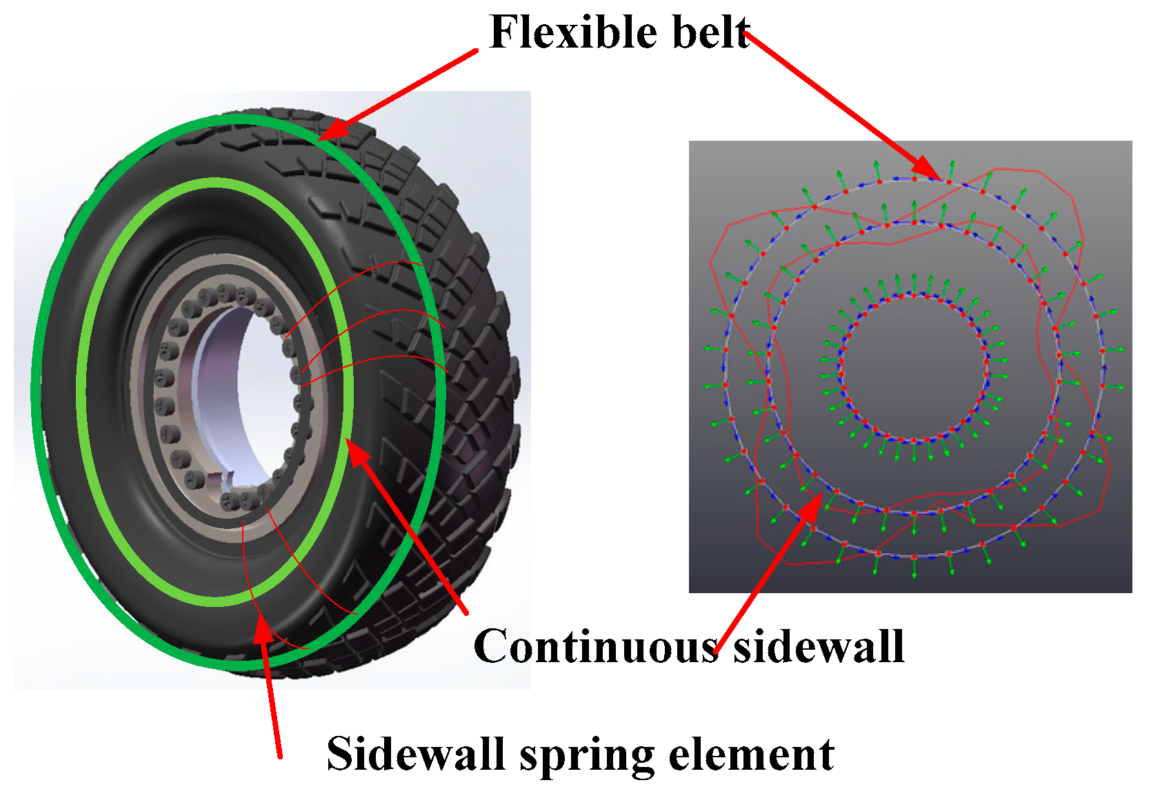
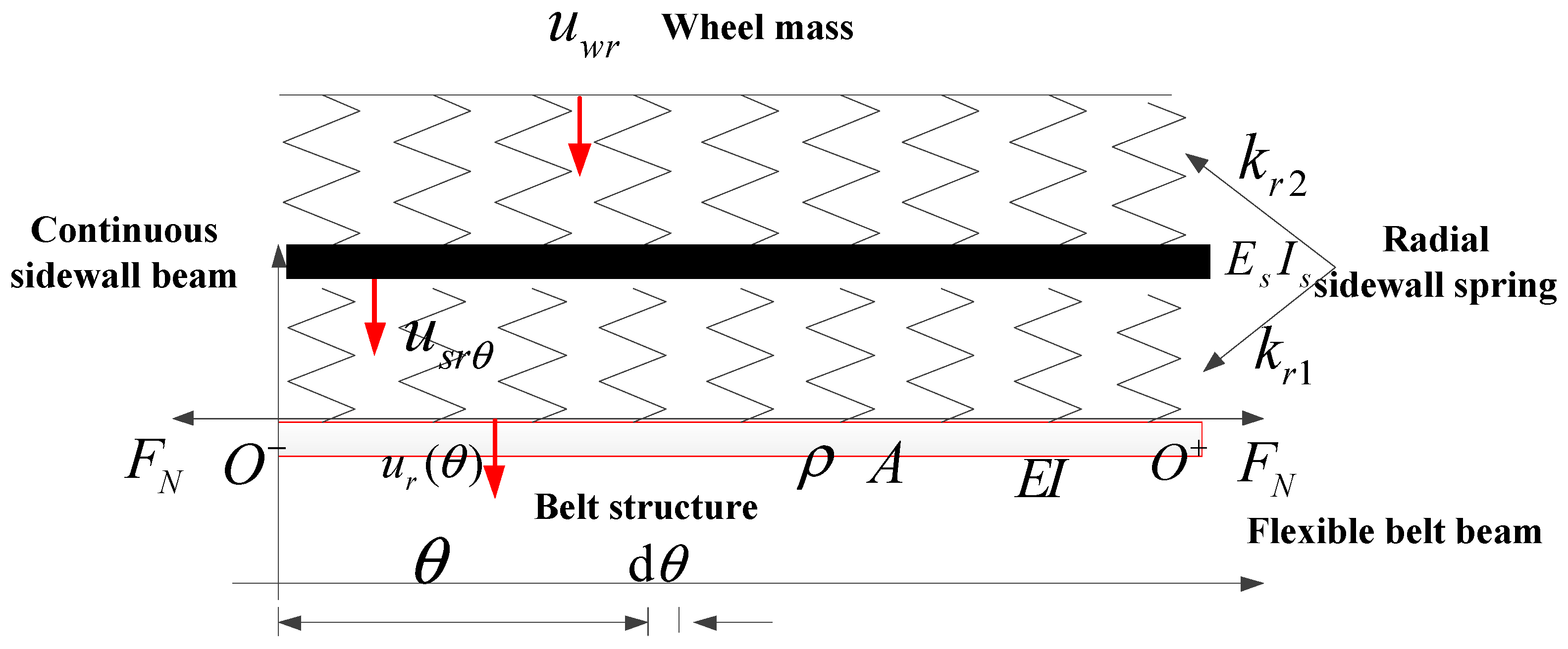
2.1. Flexible Beam on an Elastic Continuous Sidewall Beam Tire Model
The schematic diagram of the flexible beam on an elastic continuous sidewall beam tire model is shown in Figure 2. The bending deformation of the flexile belt and the pre-tension axle force resulting from the inflation pressure was considered. Additionally, the sectional stiffness of the sidewall radial spring and the bending feature of the continuous sidewall beam were added to enrich the one-dimensional tire model. and are, respectively, the horizontal displacement of the flexible belt beam and the continuous sidewall beam at time at point ; and are, respectively, the bending stiffness of the flexible belt beam and the continuous sidewall beam; is the density per line of the belt beam and is the density per rad of the continuous sidewall beam; and are the radial stiffness of the sectional sidewall spring model; and are, respectively, the belt radii and sidewall ring radii; is the pre-tension force due to the inflating pressure and , where is inflation pressure; and is belt width.
Figure 2.
Schematic diagram of the flexible beam on elastic continuous beam tire model.
Equation (1) illustrates the coupling kinematic equations of the flexible beam on an elastic continuous sidewall beam tire model: A. Equation (1a) shows the bending equation of flexible belt beam; B. Equation (1b) implies the bending equation of continuous sidewall beam; C. Equation (1c) illustrates the vibration equation of wheel.
The radial deformation of the flexible belt and the continuous sidewall is considered in the flexible beam on an elastic continuous sidewall tire model, while the coupling deformation characteristic of the continuum mediums, such as the tire belt and the tire sidewall between the radial and tangential deformations exists. Thus, the flexible ring on an elastic continuous foundation tire model is proposed and developed with the radial and tangential deformation of flexible belt ring and the continuous sidewall ring.
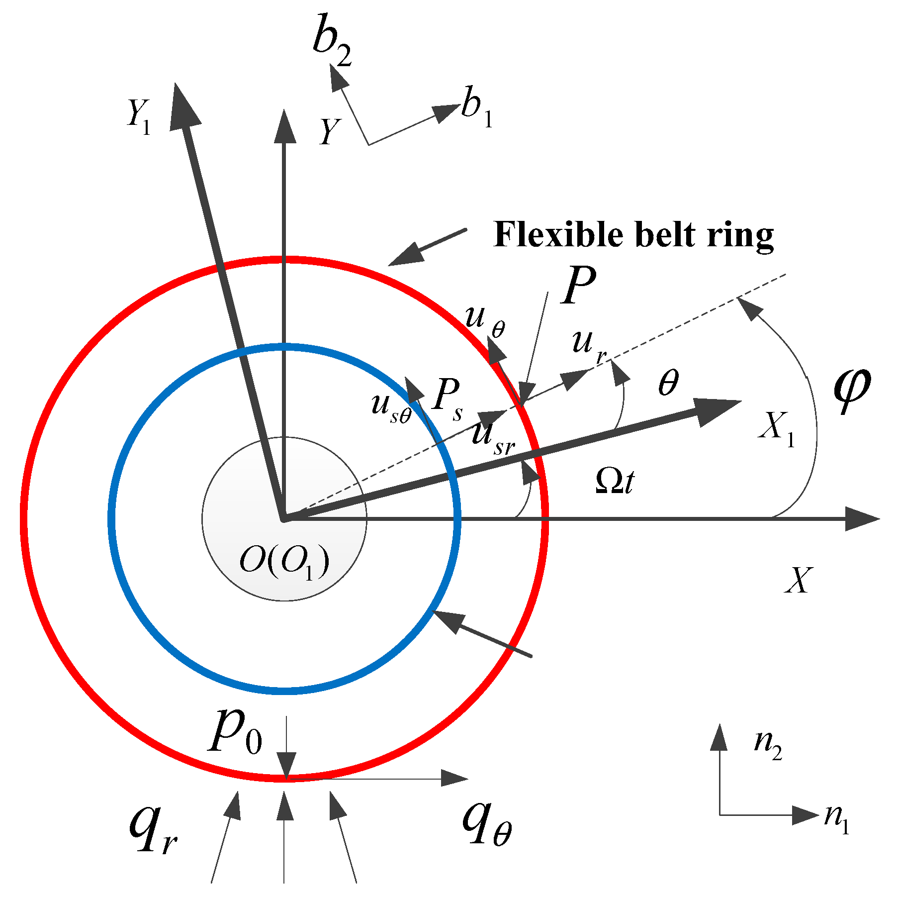
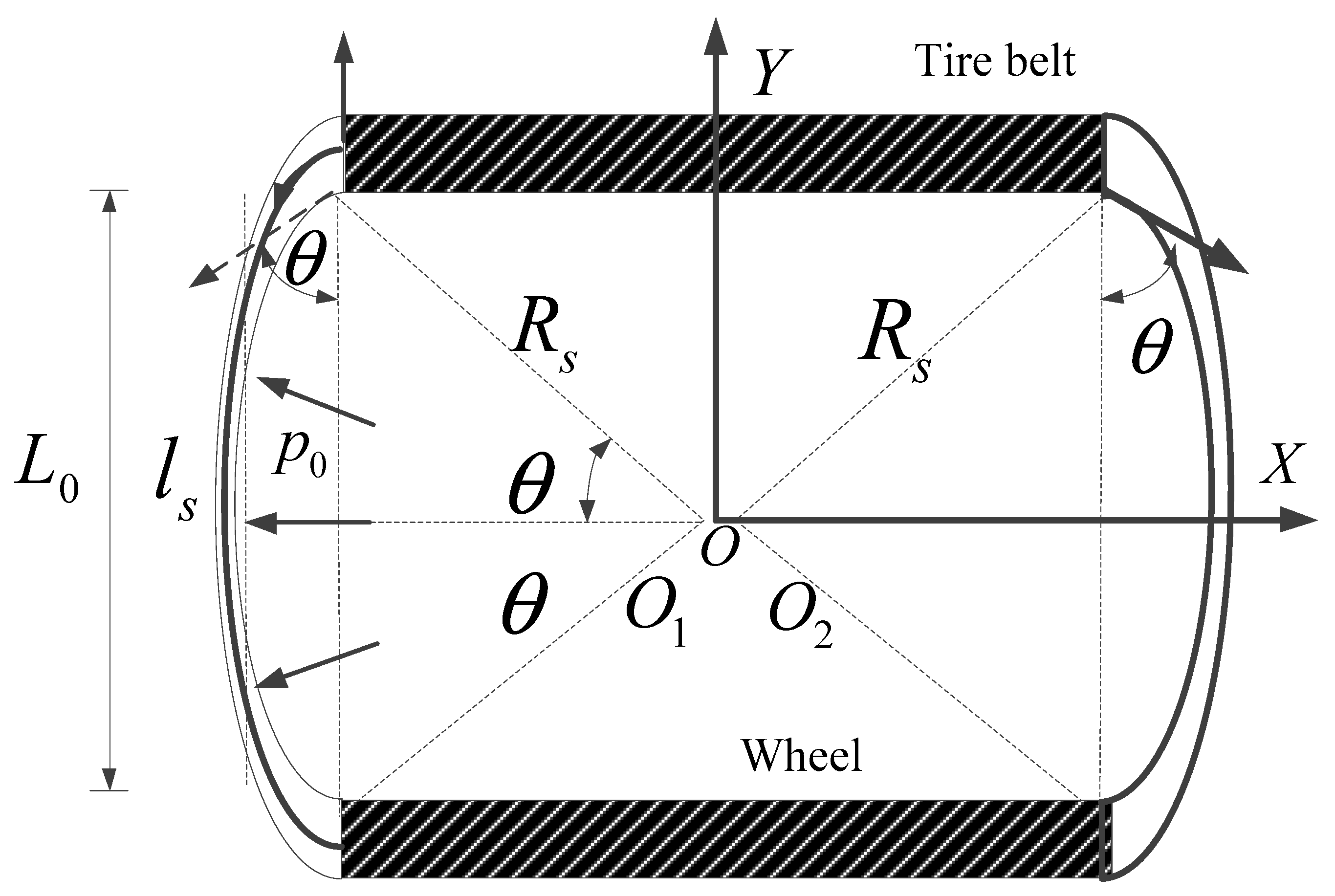
2.2. Flexible Ring on an Elastic Continuous Sidewall Ring Tire Model
The schematic diagram of the proposed two dimension tire model for the heavy load radial tire with a large flat ratio is illustrated in Figure 3. Meanwhile, the three-dimensional coordinate system, named as OXYZ, is shown, in which XOY shows the planar circumferential vibration characteristic of the heavy load radial tire, and YOZ and XOZ illustrate the cross-sectional and out-of-plane vibration characteristic of the heavy load radial tire.
Figure 3.
Schematic diagram of the flexible ring on an elastic continuous foundation tire model.
The main focus of the paper is the circumferential vibration of the heavy load radial tire, so the theoretical modeling and experimental modal analysis of the heavy load radial tire with a large flat ratio is limited within XOY.
With the coupling feature between the radial and tangential deformation of the flexible belt ring and the continuous sidewall ring, the two dimension tire model with a flexible ring on an elastic continuous foundation is developed from the flexible beam on an elastic continuous sidewall beam tire model.
Some important assumptions are highlighted as:
- (1)
- The cross-sections of the flexible belt ring and the continuous sidewall ring keep plane feature and is perpendicular to the middle section during the tire deformation;
- (2)
- The temperature and the inflation pressure keep stable during the tire deformation; and
- (3)
- Considering the decoupling feature between the out of-plane vibration and the planar circumferential vibration, the out of-plane vibration of the tire is ignored.
The flexible ring on continuous sidewall ring tire model consists of four parts:
The radial stiffness of the tire sidewall is modeled with the radial spring (connecting the flexible belt ring and the continuous sidewall ring) and (connecting the continuous sidewall ring and the wheel). Additionally, the tangential stiffness of the tire sidewall is featured with the tangential spring (connecting the flexible belt ring and continuous sidewall ring) and (connecting the continuous sidewall ring and the tire wheel).
A polar coordinate system with the origin point located at the ring center is adapted to the theoretical model. Two polar coordinate systems, named as and , are defined and respectively refer to the polar coordinate system with a non-rotating (fixed) and a rotating coordinate origin frame in Figure 4. , are the arbitrary points of, respectively, the flexible belt and the continuous sidewall. , respectively refer to the tangential and radial deformation of at rotating coordinate , while , respectively refer to the tangential and radial deformation of at rotating coordinate .
Figure 4.
Fixed and rotating coordinate frame of the proposed tire model.
The interval angles between -axis and -axis, -axis and -axis are respectively and . is the angular velocity of the rotating ring with respect to the fixed center /”:
The transformation between the coordinate of the rotating coordinate frame and coordinate of the non-rotating (fixed) coordinate frame is referred as:
2.3. Governing Equations of Hamilton Variation Principle
The kinematic equation of the rotating flexible ring on an elastic continuous foundation tire model can be obtained by applying the Hamilton principle [21]:
2.3.1. Mechanical Energy Analysis of the Tire/Wheel Assembly
The kinetic energy of the flexible belt ring, the tire wheel and the continuous sidewall ring can be referred to as , , and in Equation (5):
where is the line density of the flexible belt ring; is the rad density of the continuous sidewall ring; is the wheel mass; is the wheel moment; and are, respectively, the belt radii and sidewall ring radii; and is the rotating angle of the tire wheel.
The whole kinetic energy of the tire/wheel assembly is calculated as Equation (6):
The potential energy of the tire/wheel assembly, including strain energy of flexible belt ring and continuous sidewall ring and the spring energy of the sectional sidewall spring respectively refer to , , and .
The pre-tension strain of flexible belt ring resulting from inflation pressure is taken into consideration and the strain energy of flexible belt ring is shown in Equation (7) [22]:
where the first part of Equation (7) is the radial strain energy of the flexible belt ring and ; the second part of Equation (7) is the circumferential strain energy of the flexible belt ring and the nonlinear strain : [23]; and the third part of Equation (7) is the initial strain energy of flexible belt ring and is the initial strain resulting from the inflation pressure and the centrifugal force caused by rotation and calculated as Equation (8) in Figure 5:
Figure 5.
Pre-tension strain of flexible belt ring due to the inflation pressure and rotation.
Thus, .
The strain energy of continuous sidewall ring is shown in Equation (9):
where the first part of Equation (9) is the radial strain of continuous sidewall ring; the second part of Equation (9) is the circumferential strain energy of continuous sidewall ring and the nonlinear strain :; the third part of Equation (9) is the initial strain energy of continuous sidewall ring; and is the initial strain resulting from the centrifugal force caused by rotation, .
The spring energy of the radial and tangential sectional sidewall stiffness:
The potential energy of tire/wheel assembly is summed up as Equation (11):
2.3.2. Work Done by the Applied Forces
The work done by the applied forces consists of two parts, including due to the inflation pressure, and related with and as illustrated in Figure 4.
can refer to the product of the middle section area of the flexible belt and the ring width, in which the middle section area of flexible belt is calculated as:
So, and is obtained as:
where, , , and Equation (14) can be simplified as:
, related with and , is derived as:
2.3.3. Kinematic Dynamics of Flexible Ring on an Elastic Continuous Sidewall Ring Tire Model
Equation (5) (kinetic energy of the tire/wheel assembly), Equation (11) (potential energy of the tire/wheel assembly) and Equation (12) are substituted into Equation (4) and the independent variables, including , , , , , , and , are manipulated. With the means of the variation principle, the planar coupling kinematic equations between the flexible belt and the continuous sidewall are obtained as:
where Equation (17a) gives the radial vibration equation of the flexible belt ring; Equation (17b) shows the tangential vibration equation of the flexible belt ring; Equation (17c) gives the radial vibration equation of the continuous sidewall ring; Equation (17d) presents the tangential vibration equation of the continuous sidewall ring; Equation (17e,f,g) respectively illustrate the horizontal, vertical, and rotating movement of the wheel.
3. Planar Modal Characteristic of Heavy Load Radial Tire
The planar modal experiment of the heavy load radial tire with a large flat ratio was implemented to investigate the coupling feature between the flexible belt ring and continuous sidewall ring.
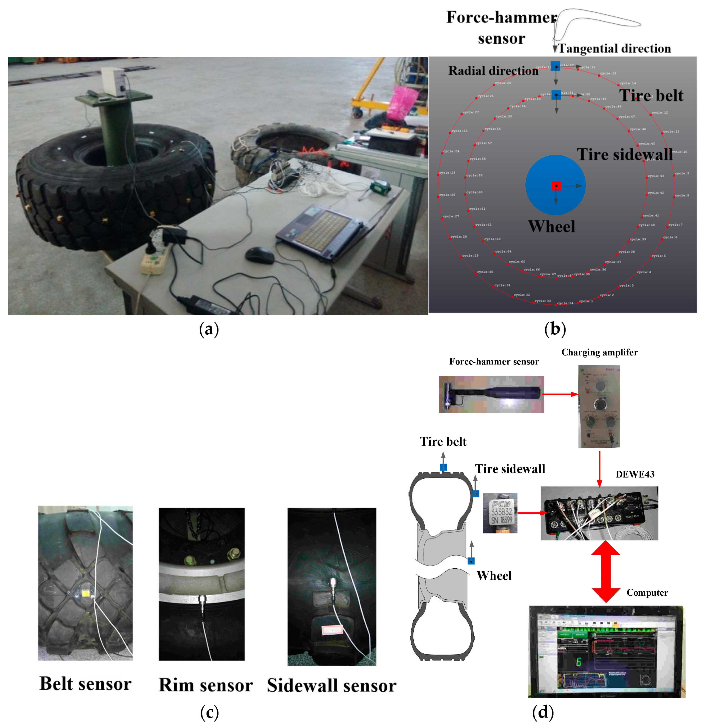
3.1. System Implementation of the Experimental Modal Analysis
Figure 6b shows the schematic diagram of the planar modal experiment of the heavy load radial tire and an experimental hammer test is implemented, the principal features of which are shown in Figure 6a. The system implementation of the experimental modal analysis consists of three main parts, including the excitation part, response part and the data analysis part.
Figure 6.
Schematic diagram of the modal analysis system implementation; (a) experimental picture of the modal analysis; (b) schematic picture of the modal analysis; (c) experimental acceleration sensors; and (d) hardware implementation of the modal analysis.
Vibration excitation is realized using a B&K hammer sensor (Naerum, Denmark), with the input force of the hammer sensor being measured by a force transducer. The PCB accelerometer sensors (PCB Piezotronics, Inc., Depew, NY, USA) are used to measure the resulting acceleration of the tire belt, the tire sidewall and the tire wheel illustrated in Figure 6c, in which the acceleration sensors are attached to the tire with a thin layer of mounting wax. Figure 6d presents the hardware system of the experimental modal analysis, in which by measuring the excitation force with the hammer sensor and the vibration response with the acceleration sensor, the input excitation force and output response acceleration are gathered using high-speed data acquisition equipment, namely a DEWE-43 (Austria).
The experimental transfer function is calculated using spectrum analysis by combining the input excitation force and the output response acceleration. Two additional methods were implemented to further improve the data quality for the measured transfer function:
- (1)
- Linear averaging was used to calculate the transfer function for every excitation point by averaging 10 repetitions of the transfer function measurement; and
- (2)
- The coherence function was checked to evaluate the quality of the measured transfer function to assess the measurement process for every excitation.
The frequency transfer functions for a heavy-load radial tire with a large aspect ratio are shown in Figure 7 to illustrate the vibration characteristics, in which, Figure 7a illustrates the three-dimensional planar transfer function between the excitation at point A and the response. Figure 7b presents the coherence value calculated from the input force and output acceleration response as a means of checking the planar transfer function; furthermore the following conclusion can be made on the basis of Figure 7:
Figure 7.
Planar acceleration transfer functions for a heavy load radial tire with normal inflation pressure: (a) Three-dimensional belt transfer function; and (b) coherence values for the three-dimensional belt.
- (1)
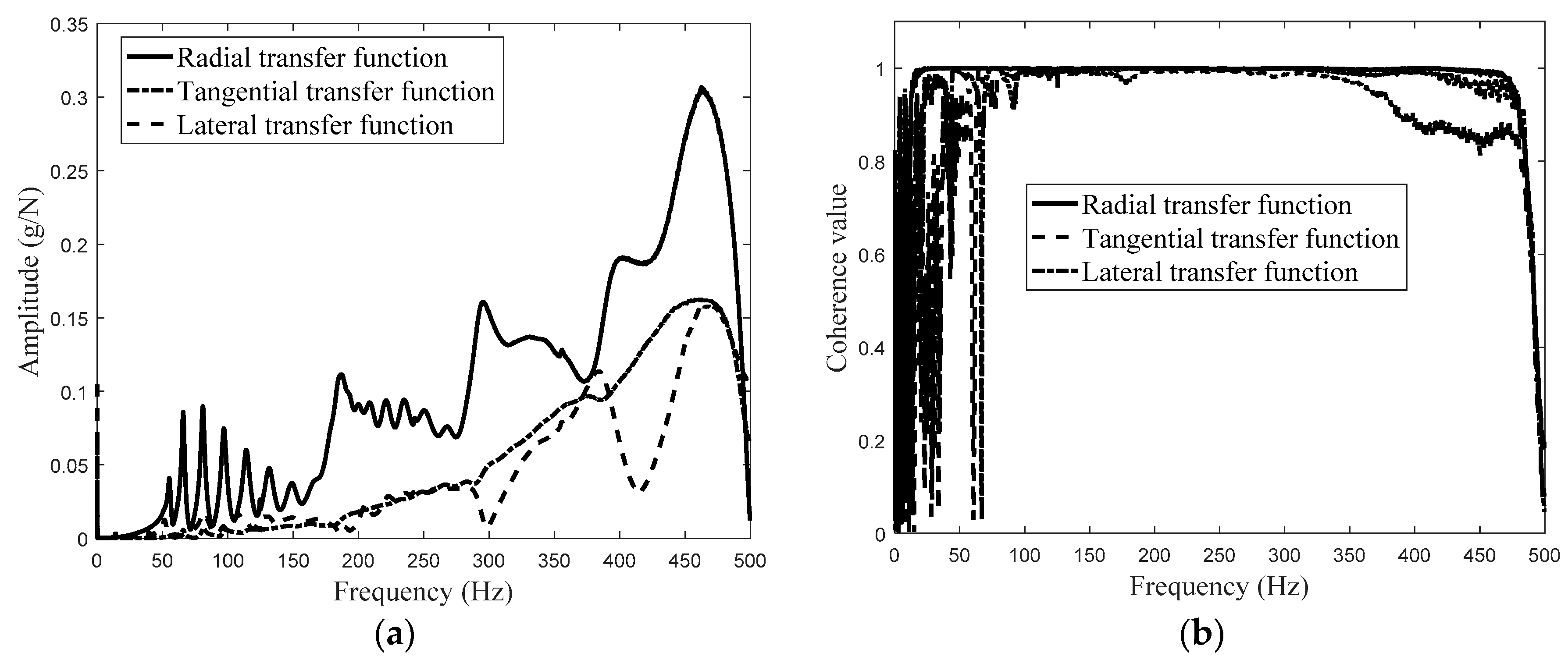
- The three-directional transfer function and coherence values for the excitation force and the response acceleration compared in Figure 7a show that the coherence value of the radial excitation force and the radial acceleration response have a difference of 1 for frequencies below 13 Hz. There is a similar difference of 1 between the coherence value for the radial excitation force and the tangential acceleration response for frequencies below 50 Hz. Beyond the above frequency band, the coherence value of the radial excitation force and the lateral acceleration response fluctuate around the frequency of 75 Hz; and
- (2)
- The larger amplitude of the radial transfer function than the tangential and lateral transfer functions implies that planar radial deformation of the flexible belt is the main vibration source for heavy-load radial tires with a large aspect ratio.
In addition to this, the sectional planar transfer function within 300 Hz can be divided into two parts: 0–160 Hz and 160–280 Hz. The sectional transfer function results for the coupling vibration between the flexible belt and the continuous sidewall, moreover, indicates that coupling vibration between the flexible belt and the continuous sidewall generally needs to be considered when undertaking vibration analysis of heavy-load radial tires with a large aspect ratio.
- (3)
- The structure-cavity coupling vibration peaks at 120 Hz (the first-order structure-cavity resonance frequency) and 240 Hz (the second-order structure-cavity resonance frequency) as shown in Figure 7a. For comparison, the first-order resonance frequency for tires with a small aspect ratio, including bus and truck tires, is typically within 230–250 Hz.
Meantime, the experimental transfer functions of the heavy load radial tire with a different inflation pressure are investigated in Figure 8.
Figure 8.
Planar acceleration transfer functions for a heavy load radial tire with a different inflation pressure: (a) Radial amplitude of the transfer functions; and (b) phase difference of the transfer function.
3.2. Modal Resonance Parameters Identification
The least square complex exponential method is utilized for the modal parameters identification, including the modal resonance frequency, modal damping, and modal shape.
Figure 7 and Figure 8 present the frequency domain vibration characteristic, meanwhile the impulse is needed. Utilizing the inverse FFT method, the impulse response function is given as:
where is the real part.
The impulse response function of the finite time form transforming from the impulse response function is given as:
where ,.
Impulse response functions of the different time can be concluded with the finite time form:
where .
Multiplying Equation (21) by , the calculated equations are summed up:
Substituting and , Equation (22) is transformed as:
Constructing Equation (23) with the time domain result to solve the autoregressive coefficient , the equation is set with the same time interval :
in which, .
Transforming Equation (24) in the matrix form, the equation set is given as Equation (25):
Utilizing the least square method, the autoregressive coefficient is gained:
In which can be given by solving the polynomial equation formed with the autoregressive coefficient . The modal parameters, including modal resonance frequency and modal damping are calculated in Equation (28) and modal shape coefficient is obtained in Equation (29):
The radial and tangential transfer functions are taken as the object transfer function; moreover, utilizing the least square complex exponential method, the modal resonance frequency and modal damping of the heavy load radial tire is identified and the identified transfer function can be calculated. Figure 9 shows the compared results between the experimental and identified transfer functions of the heavy load radial tire with a different inflation pressure. The coupling modal characteristic between the flexible belt ring and the continuous sidewall ring is identified and presented in Figure 10, including modal resonance frequency (Figure 10a), modal damping (Figure 10b), and modal shape (Figure 10c).

Figure 9.
Experimental and identified transfer functions of the excitation point and response points: (a) Real part of the transfer function (0.8 Mpa); (b) imaginary part of the transfer function (0.8 Mpa); (c) real part of the transfer function (0.7 Mpa); (d) imaginary part of the transfer function (0.7 Mpa); (e) real part of the transfer function (0.6 Mpa); (f) imaginary part of the transfer function (0.6 Mpa); (g) real part of the transfer function (0.5 Mpa); (h) imaginary part of the transfer function (0.5 Mpa); (i) real part of the transfer function (0.4 Mpa); (j) imaginary part of the transfer function (0.4 Mpa); (k) real part of the transfer function (0.3 Mpa); and (l) imaginary part of the transfer function (0.3 Mpa).
Figure 10.
Planar experiment modal result of the heavy load radial tire with a large flat ratio; (a) modal resonance frequency with different inflation pressure; (b) modal damping with different inflation pressure; (c) four-sectional modal shape; and (d) five-sectional modal shape.
The compared transfer functions illustrated in Figure 9 show that the discrepancy between the identified transfer functions and the experimental transfer functions of the heavy load radial tire with a different inflation pressure is small, which validates that the least square complex exponential method can satisfy the identification precision as the sixteen orders resonance frequencies existing within 300 Hz.
To conclude:
- (1)
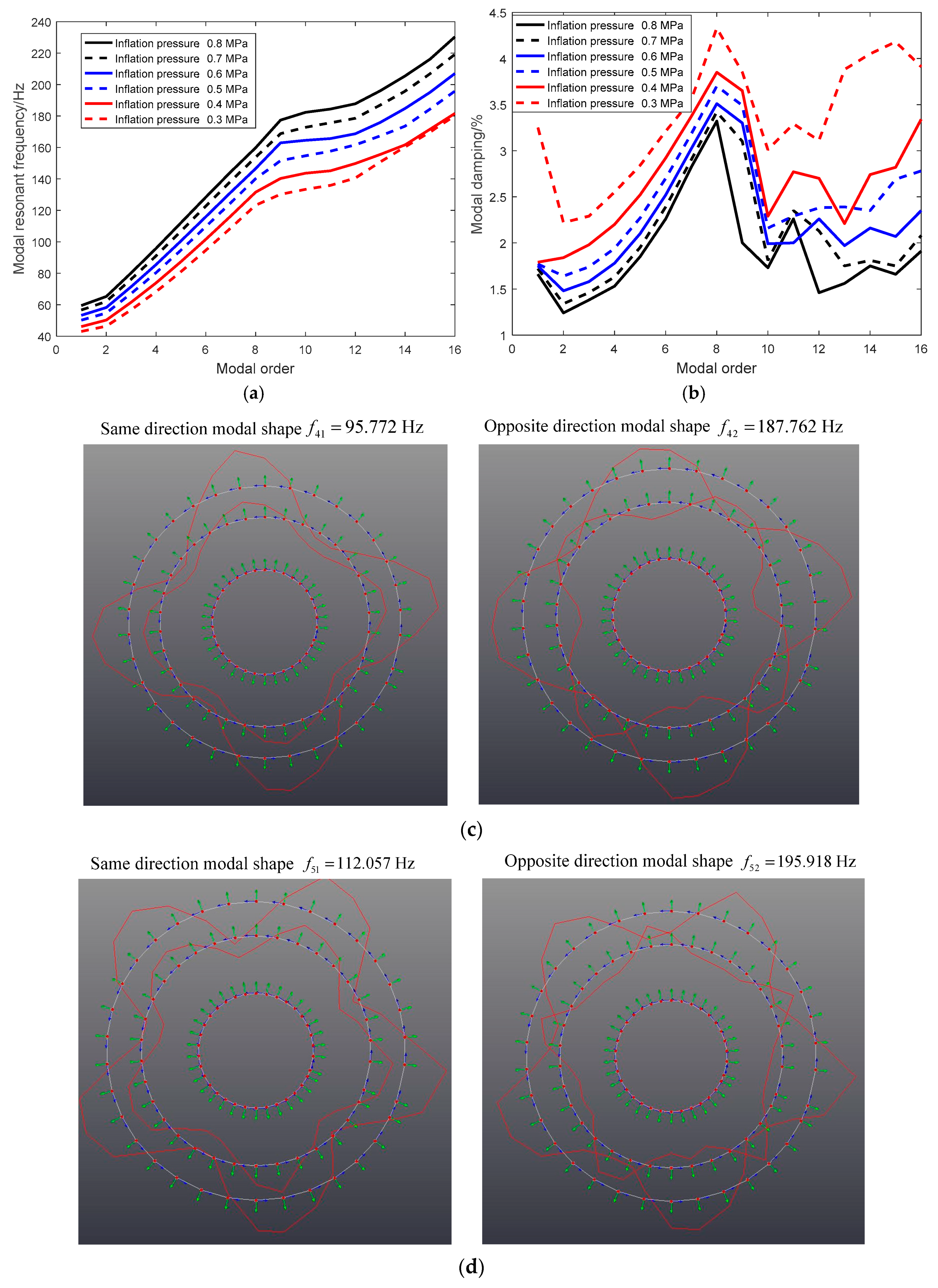
- The sixteen orders modal parameters of the heavy load radial tire are identified within 300 Hz;
- (2)
- The two typical features of the heavy load radial tire resulting from the large flat ratio appear as:
- (3)
- The modal shapes of the heavy load radial tire is harmonic, while the vibration direction of flexible belt and continuous sidewall is different in the low and medium frequency band. The modal shape of the heavy load radial tire within the low frequency is the coupling vibration of flexible belt and continuous sidewall with the same direction, while the modal shape within the medium frequency band is the coupling vibration of flexible belt and continuous sidewall with the opposite direction.
4. Analytical Coupling Modal of the Flexible Belt and the Continuous Sidewall
4.1. Simplification Forms of the Kinematic Equation
The in-extensibility assumption [23] (the circumferential length of the middle surface of the flexible ring, such as the tire belt and the tire sidewall, is constant during tire deformation) is utilized to simplify the dynamic equation of flexible belt:
Substituting Equation (30) into Equation (17a,b), then differentiating Equation (17a) with respect to and adding it to Equation (17b), the kinematic equation of the flexible belt ring with the in-extensibility belt ring assumption is transformed as:
Moreover, the in-extensibility assumption is also used to simplify the dynamic equations of the continuous sidewall ring (the circumferential length of the middle surface of the flexible belt ring and the continuous sidewall ring is constant during the deformation).
The vibration characteristic of the continuous sidewall ring is same or opposite to the flexible belt ring and the in-extensibility assumption can be used to simplify the dynamic equation of the continuous sidewall ring with the similar form as:
The radial and tangential equations of the continuous sidewall ring are transformed as:
The harmonic vibration characteristic of the heavy load radial tire is influenced by the material and geometrical parameters of the tire, moreover is independent with the wheel motion. The wheel is assumed to be fixed and non-rotating, so:
The kinematic equations of the proposed flexible ring on an elastic continuous foundation tire model are transformed as:
4.2. Modal Solution of the Planar Coupling Vibration between the Flexible Belt and the Continuous Sidewall
The rotating feature and the movement of wheel is taken into the completing kinematic equations (Equation (17)) and the simplified forms of the proposed tire model with the In-extensibility assumption are derived as Equation (35). Planar coupling vibration characteristic between the flexible belt ring and the continuous sidewall ring would be further investigated and solved with modal expansion method. The free vibration mode of the flexible belt and the continuous sidewall is assumed in the sinusoidal series illustrated in Equation (36), in which, Equation (36a,b) respectively refer to the circumference vibration modal of the flexible belt ring and the continuous sidewall ring:
Substituting Equation (36) into Equation (35), the planar dynamics of the heavy load radial tire with a large flat ratio are given as:
where , , .
The kinematic equation (Equation (37)) is reorganized as:
The roots of Equation (38) are obtained as Equation (39). Meanwhile, the deformation relationship between the flexible belt ring and the continuous sidewall ring refers to Equation (40):
Analytical modal resonance frequency of the flexible belt ring and the continuous sidewall ring is derived as:
The deformation relationship between the flexible belt ring and the continuous sidewall ring is concluded as:
The coupling relationship of the flexible belt and the continuous sidewall is discussed by comparing the two roots of Equation (29).
The Equation (32) is the identical equation and substituted into Equations (42) and (43) respectively.
Substituting Equation (44) into Equations (42) and (43), the conclusion is made that:
- (1)
- , substituting Equation (44) into Equation (42) and ;
- (2)
- , substituting Equation (44) into Equation (43) and ;
- (3)
- The positive ratio of and with implies the same vibration direction of flexible belt ring and continuous sidewall ring, which is consistent with Figure 10c,d and the conclusion given by the flexible beam on an elastic continuous sidewall beam tire model [23]; and
- (4)
- The negative ratio of and with implies the opposite vibration direction of flexible belt ring and the continuous sidewall ring, which is consistent with Figure 10c,d, and the conclusion given by the flexible beam on an elastic continuous sidewall beam tire model [23].
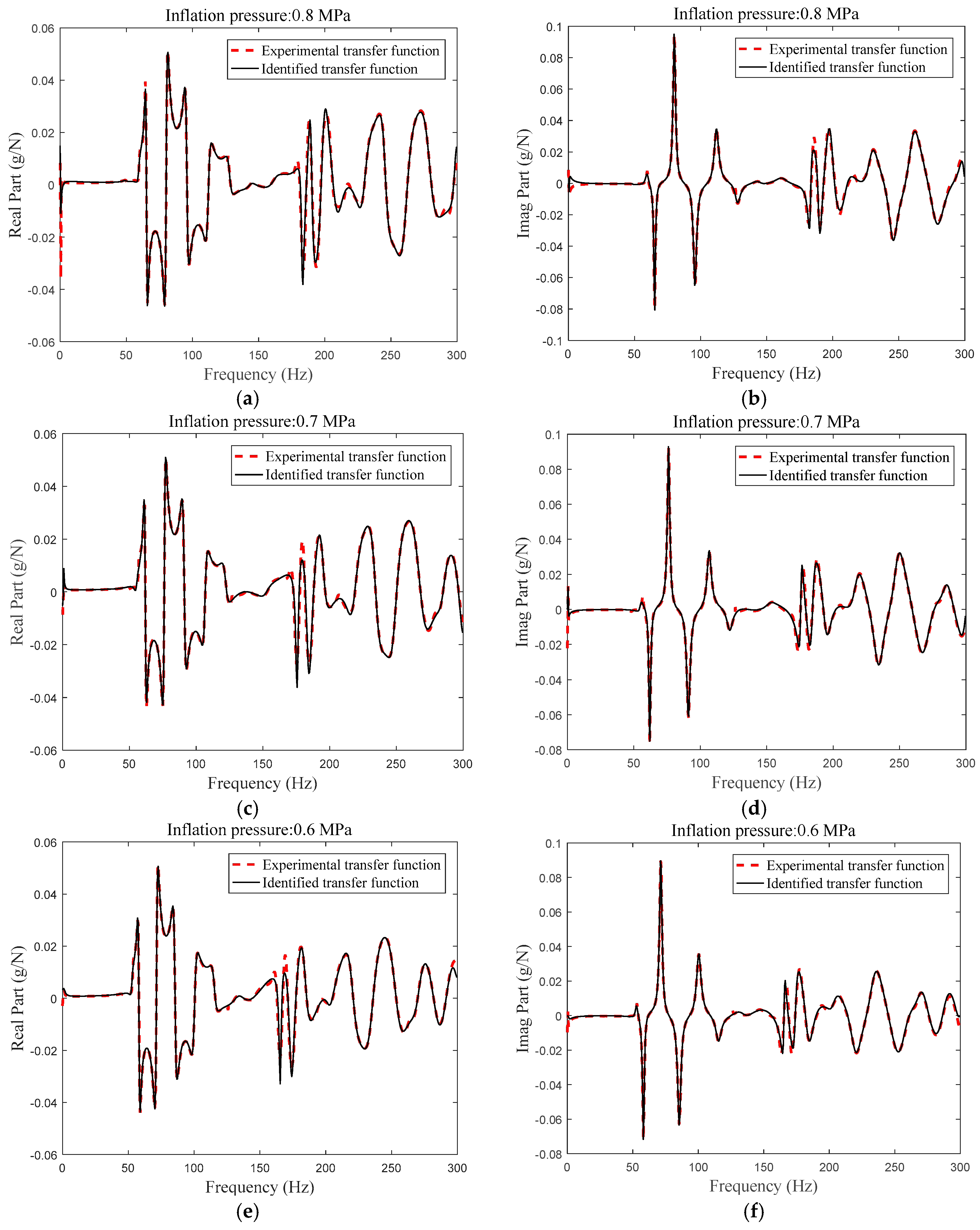
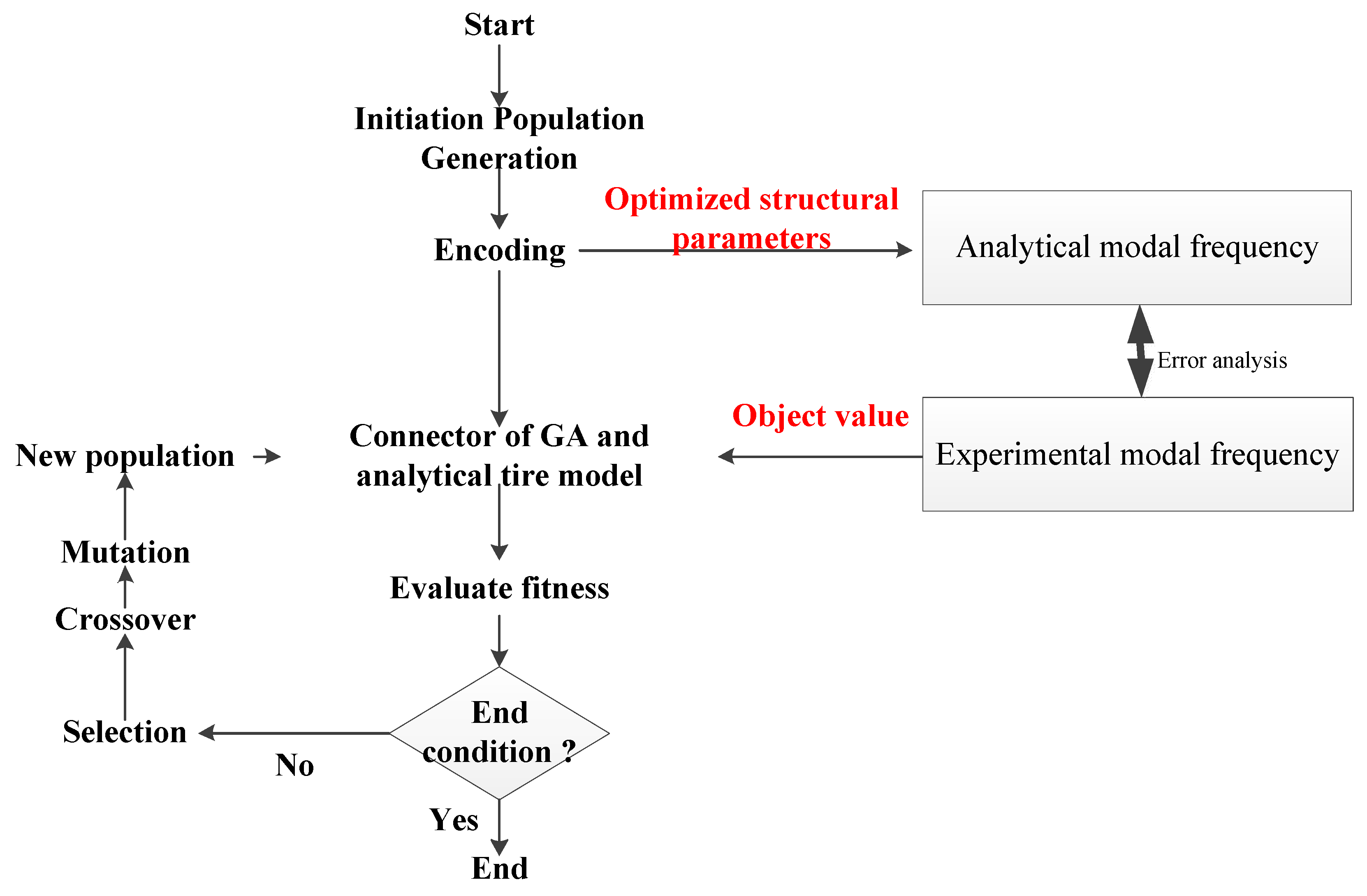
5. Structural Parameters Identification
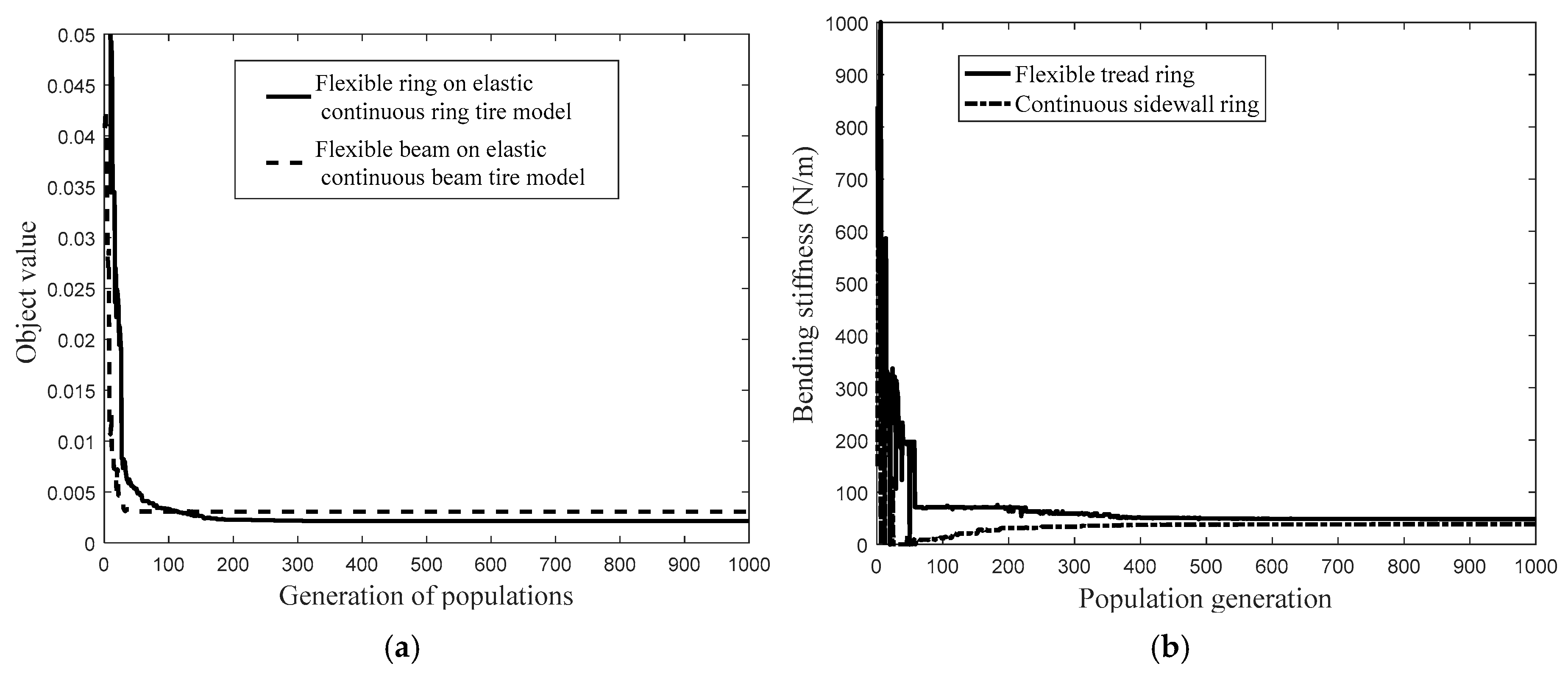
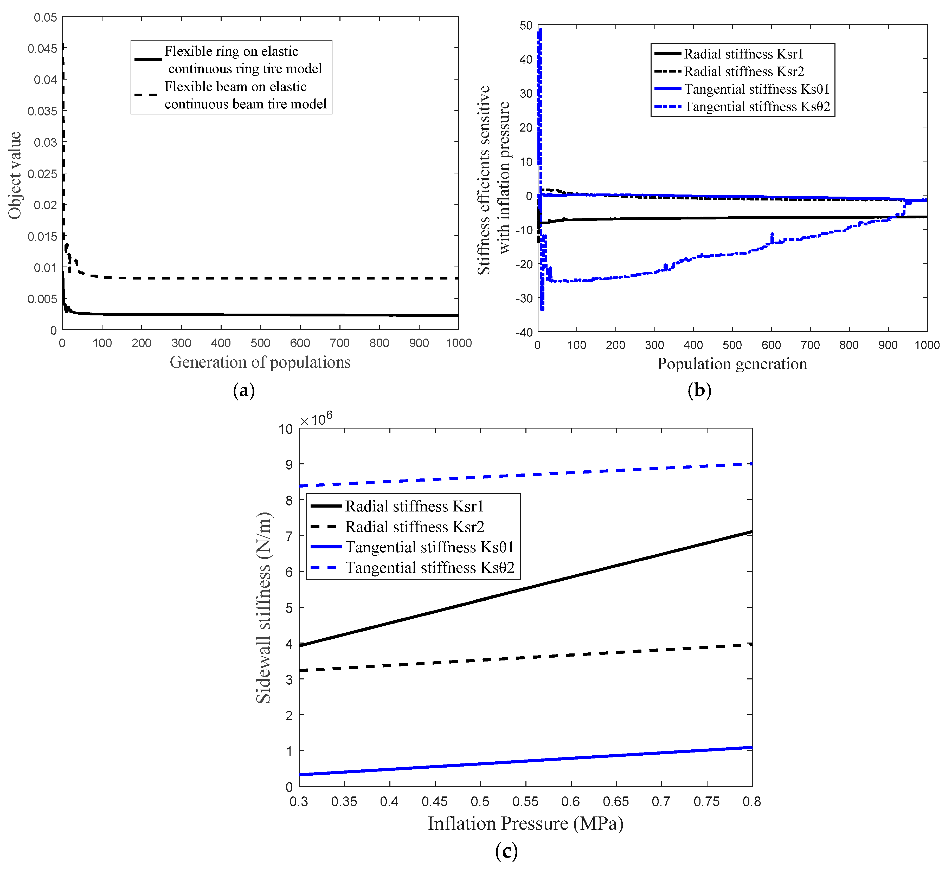
With the disassembly of the heavy load radial tire (Figure 11), some geometrical parameters can be measured directly; meanwhile, some material parameters of the proposed tire model cannot be measured directly and the intelligent algorithm [24] is utilized to identify the unknown material parameters. The parameters of the proposed tire model are listed in Table 1. Taking the error between the experimental modal resonance frequency (Figure 10a modal resonance frequency of heavy load radial tire with normal inflation pressure) and analytical modal resonance frequency (Equation (41)) as the object value, a genetic algorithm (GA) is utilized to identify the unknown structural parameters illustrated in Table 1.
Figure 11.
Disassembled tire test.
Table 1.
Geometrical and structural parameters of the GL073A tire.
The optimization procedure is initialized with a population size of 20, 1000 generations, a generation gap of 0.9, a crossover rate of 0.7, and a mutation rate of 0.1. The major components of the GA are the encoding scheme, fitness evaluation, parent selection, crossover, and mutation operators, illustrated in Figure 12.
Figure 12.
Scheme diagram of the structural parameters identification utilizing GA.
Figure 13 presents the structural parameters of the optimization procedure. The identified result utilizing the flexible ring on an elastic continuous foundation tire model is compared with that using the flexible beam on an elastic continuous sidewall beam tire model and the compared results are shown in Table 2.

Figure 13.
Identification procedure of unknown structural parameters. (a) The compared object value between the flexible ring on an elastic continuous sidewall ring tire model and flexible beam on an elastic continuous sidewall beam tire model; (b) the bending stiffness of flexible belt ring and continuous sidewall ring; (c) the sectional radial stiffness of sidewall spring; and (d) the sectional tangential stiffness of sidewall spring.
Table 2.
Identified parameters of the GL073A tire.
- (1)
- The object value of the parameters identification procedure (Figure 13a) is convergent to the steady point with the optimization procedure proceeding to 200 generations;
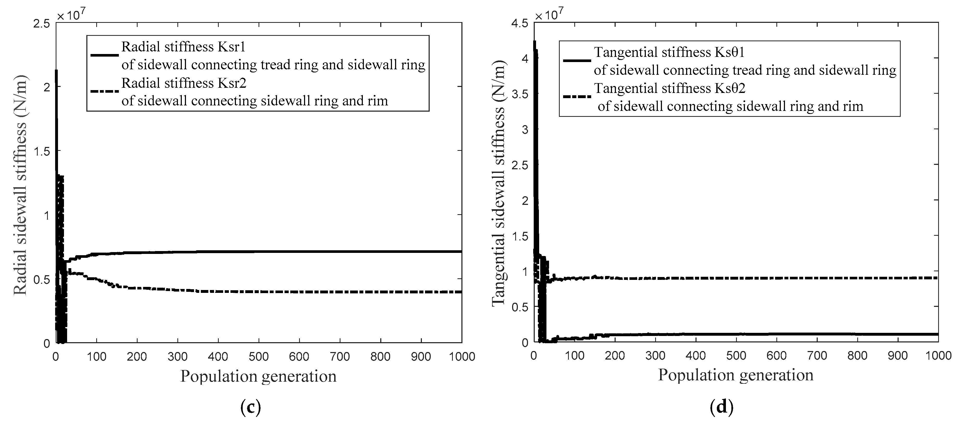
- (2)
- The structural parameters, including: bending stiffness ,, and sidewall stiffness , , and , converge to the optimum solution as the optimization procedure proceeding 400 generations;
- (3)
- The steady object value of identification procedure utilizing the flexible ring on an elastic continuous sidewall ring tire model is compared with that utilizing the flexible beam on an elastic continuous sidewall beam model in Figure 13a. The compared identification procedure implies that the model prediction error using flexible ring on an elastic continuous sidewall ring tire model is less than that utilizing the flexible beam on an elastic continuous sidewall beam model resulting from taking the coupling feature between the radial and tangential deformation of flexible belt ring and continuous sidewall ring into consideration;
- (4)
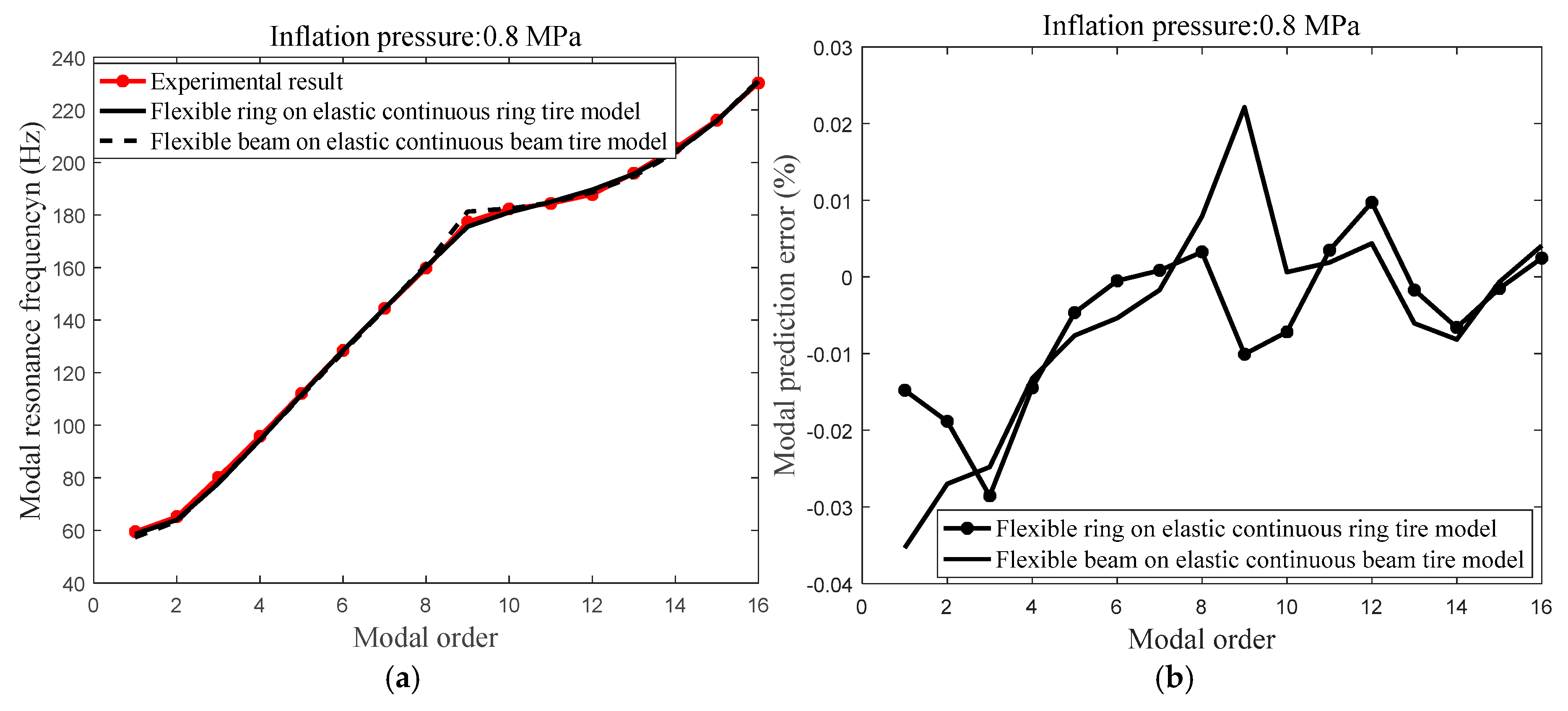
- Table 2 illustrates the identified structural parameters respectively using flexible ring on an elastic continuous sidewall ring tire model and flexible beam on an elastic continuous sidewall beam tire model. The structural parameter bending stiffness of the continuous sidewall ring , identified using the flexible ring on an elastic continuous sidewall ring tire model, is less and the structural parameters bending stiffness of flexible belt ring , and sidewall spring stiffness , are larger than that using the flexible beam on an elastic continuous sidewall beam tire model;
- (5)
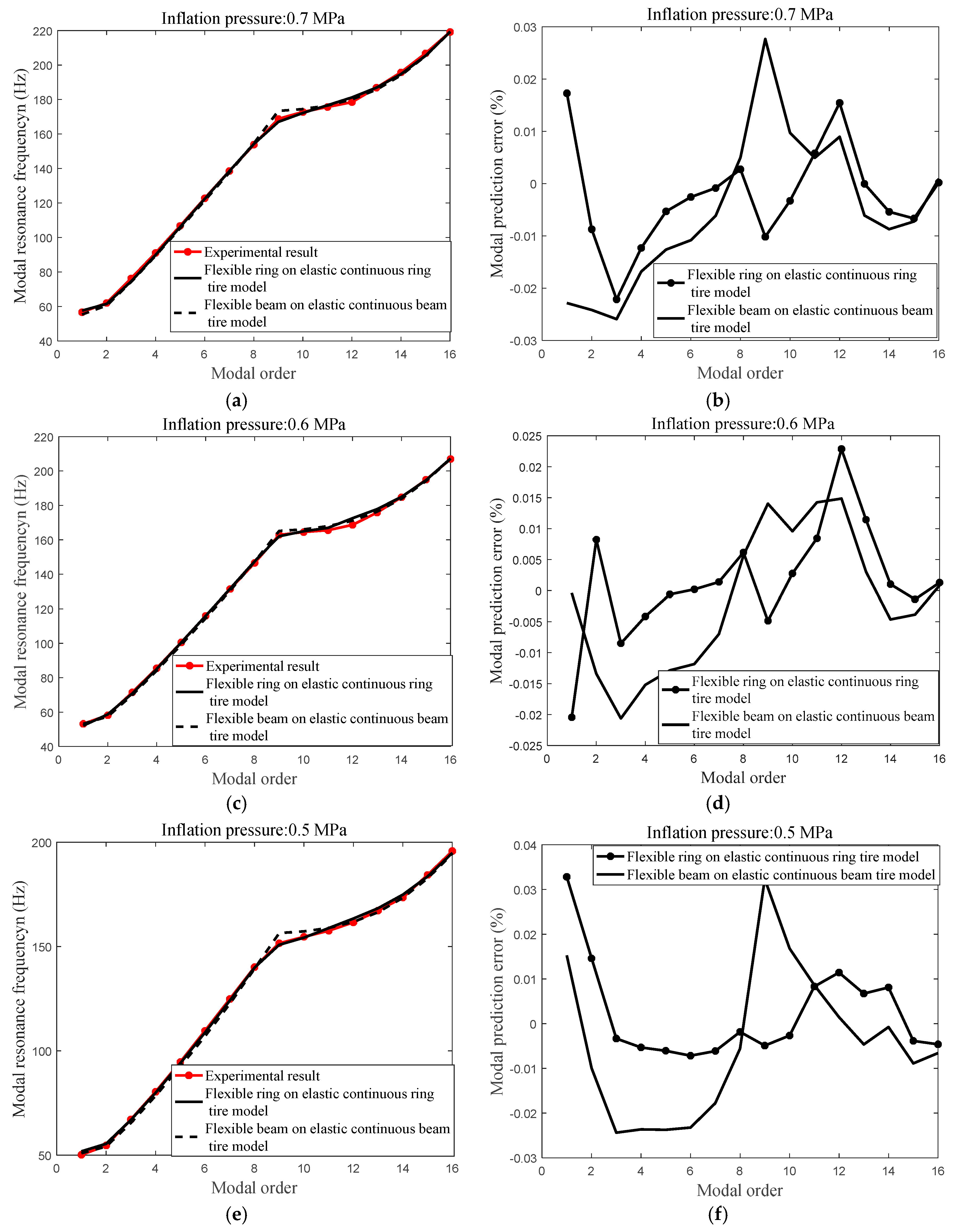
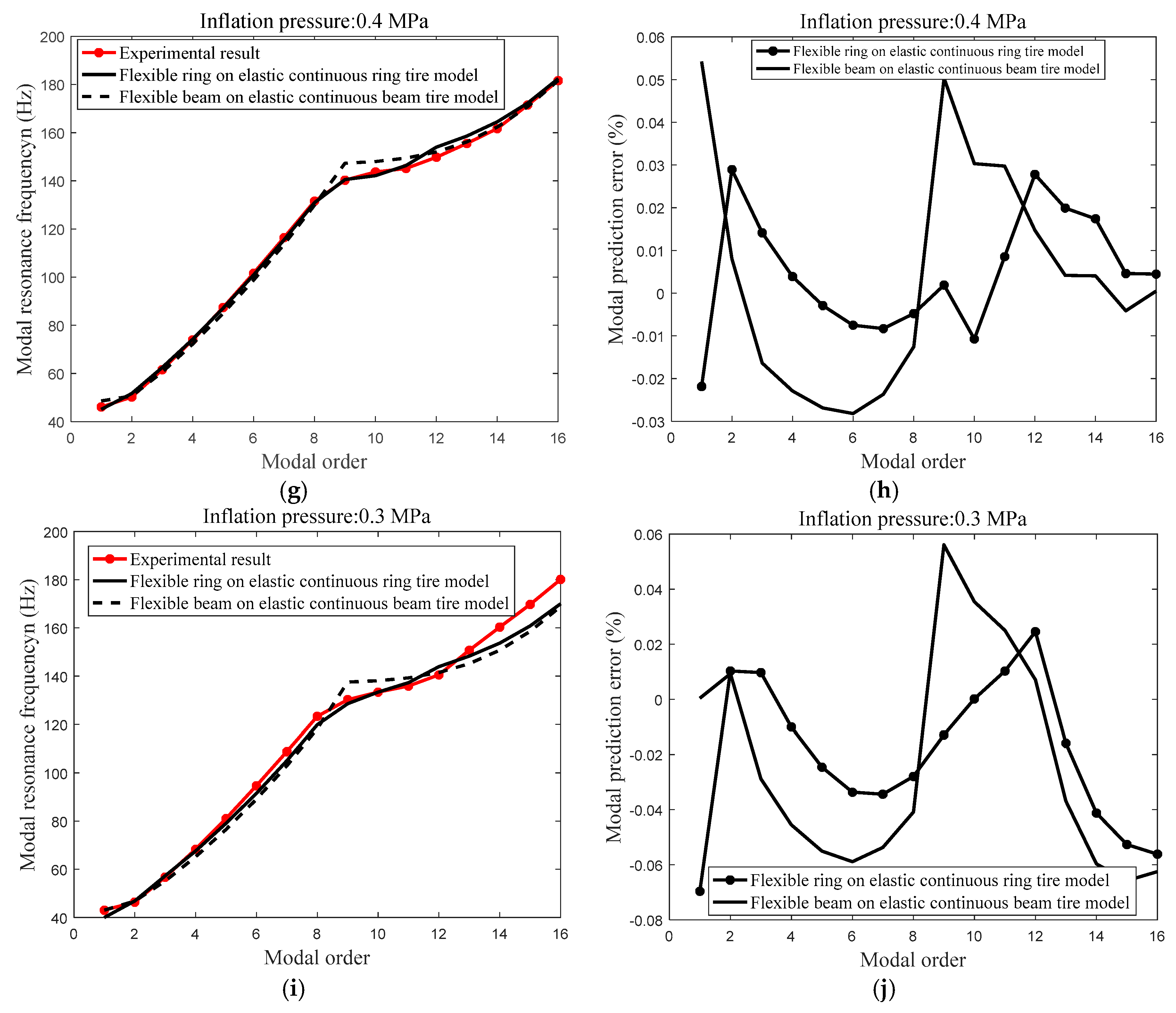
- Figure 14 shows the compared modal resonance frequency of experimental modal resonance frequency (Figure 14b) and the analytical modal resonance frequency, respectively by the flexible ring on an elastic continuous sidewall ring tire model and flexible beam on an elastic continuous sidewall beam tire model; the compared result shows that the error between the analytical modal frequency with normal inflation pressure of the flexible ring on an elastic continuous sidewall ring tire model, and the experimental modal frequency is limited within 3% and less than that of the analytical modal frequency of the flexible beam on an elastic continuous sidewall beam tire model.
Figure 14. Modal prediction with the identified structural parameters; (a) the compared modal resonance frequency between the experimental modal resonance frequency, predicted modal resonance frequency utilizing the flexible ring on an elastic continuous sidewall ring tire model and predicted modal resonance frequency utilizing flexible beam on an elastic continuous sidewall beam tire model; and (b) the compared modal prediction error between predicted modal resonance frequency utilizing the flexible ring on an elastic continuous sidewall ring tire model and predicted modal resonance frequency utilizing flexible beam on an elastic continuous sidewall beam tire model.
6. Discussion
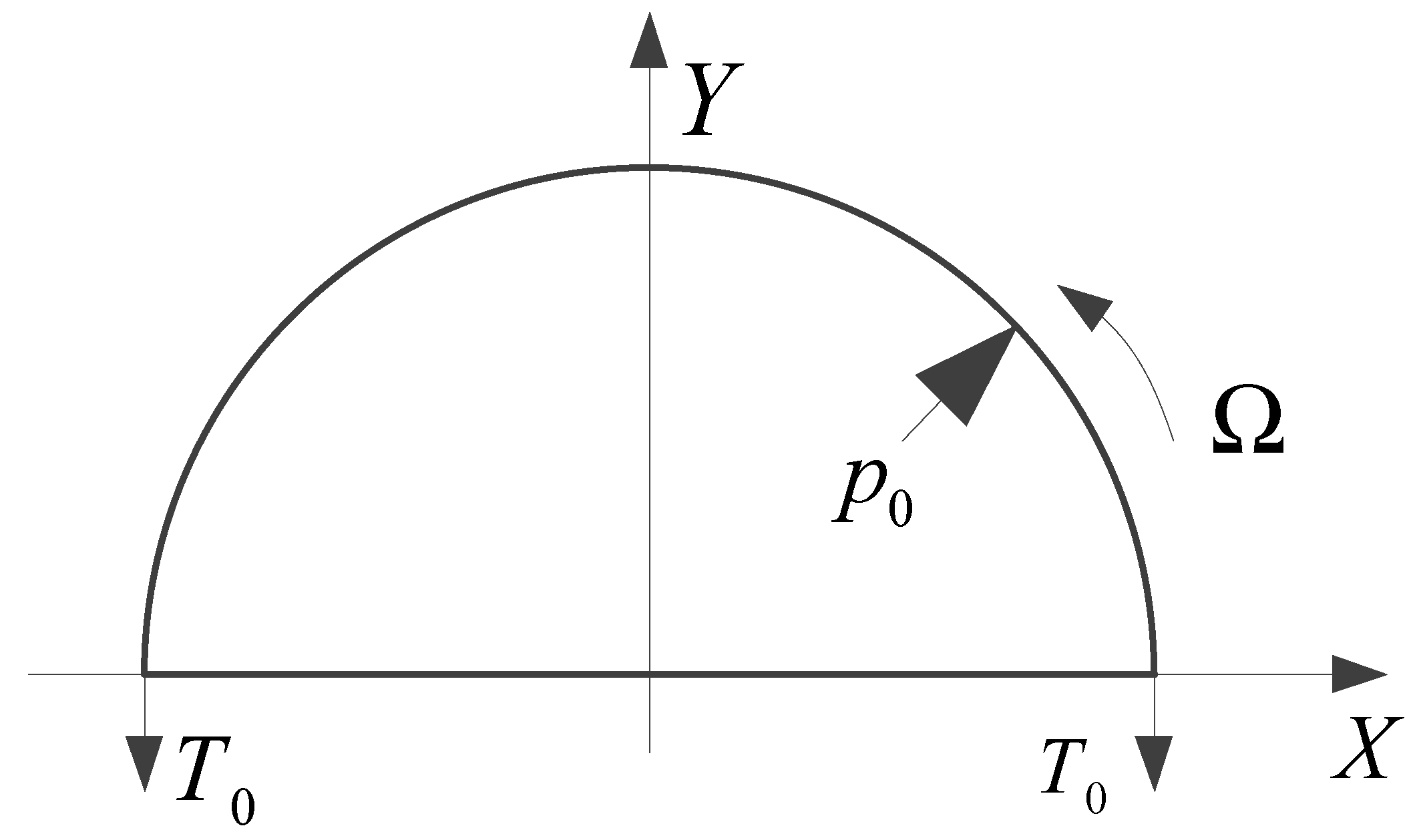
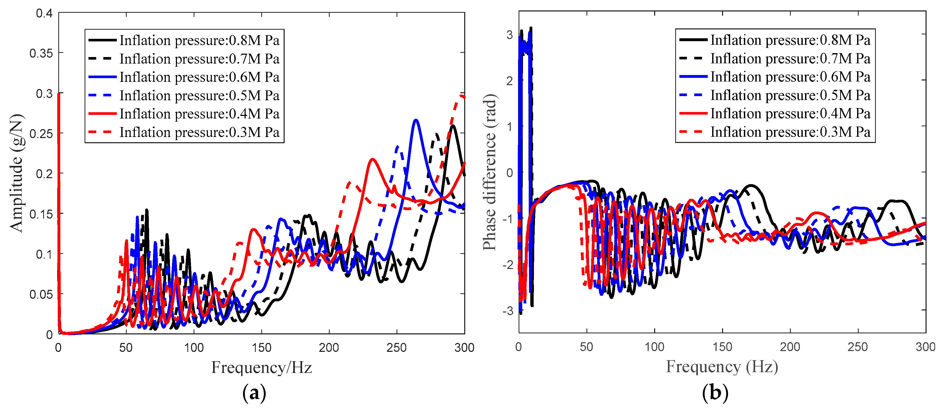
6.1. Variations of Inflation Pressure on the Planar Characteristic
Influence of the inflation pressure on the planar characteristic of the heavy load radial tire consists of two sections:
- (1)
- The pre-tension strain of flexible belt ring resulting from the inflation pressure; and
- (2)
- The variation of the sidewall pre-tension force caused from inflation pressure.
Figure 15 shows the geometrical characteristic of the sidewall arc in which is the radius of the sidewall uniform arc; is the interval angle; is the length of sidewall arc; is the initial vertical distance between the belt and rim; and are, respectively, the centers of the two-piece sidewall.
Figure 15.
Non-linear geometrical feature of the sidewall arc.
The variation of sidewall radial spring stiffness was discussed [25] and the analytical radial stiffness of sidewall was derived as:
where is the radial stiffness of the sidewall spring.
Radial stiffness of the sidewall is sensitive with the inflation pressure and the geometrical feature. Related work has been done by other researchers and the tangential stiffness of the sidewall spring [25] is derived analytically as:
The intersection angle between the tire belt and the sidewall arc is assumed invariable as stretching and compressing deformation of sidewall and the radial stiffness and the tangential stiffness of the sidewall are proportional to the inflation pressure .
Thus, radial and tangential stiffness of the tire sidewall with a different inflation pressure (illustrated in Equations (45) and (46)) refers to:
where , are, respectively, the radial stiffness of the tire sidewall with normal inflation pressure condition; , are, respectively, the tangential stiffness of the tire sidewall with normal inflation pressure condition; is the normal inflation pressure; , are, respectively, the proportional coefficients of sidewall radial stiffness; and , are, respectively, the proportional coefficients of sidewall tangential stiffness.
6.2. Stiffness Coefficients Identification Using a GA
The proportional coefficients of sidewall stiffness sensitive with the inflation pressure are identified utilizing a GA with the modal prediction error of different inflation pressure as the object value. The optimization procedure is initialized with the same parameters list in Section 5 and the identification results of the identification procedure is presented in Figure 16.
Figure 16.
Stiffness coefficients identification procedure; (a) compared object value of flexible ring on an elastic continuous foundation tire model and flexible beam on an elastic continuous sidewall beam tire model; (b) stiffness coefficients of the sidewall spring model; (c) radial and tangential stiffness of the sidewall spring model with a different inflation pressure.
Figure 16a presents the compared object value of flexible ring on an elastic continuous foundation tire model and flexible beam on an elastic continuous sidewall beam tire model. Additionally, Figure 16b shows the stiffness coefficients of the sidewall spring model of the identification procedure and the Figure 16c illustrates the radial and tangential stiffness of the sidewall spring model with a different inflation pressure.
Table 3 lists the identified stiffness coefficients of the sidewall spring model, which is sensitive with the inflation pressure.
Table 3.
Identified stiffness coefficients sensitive to inflation pressure.
Figure 17 presents the compared modal resonance frequency (inflation pressure: 0.7, 0.6, 0.5, 0.4, and 0.3 MPa) between the experimental modal resonance frequency, analytical modal resonance frequency, respectively utilizing the flexible ring on an elastic continuous foundation tire model and flexible beam on an elastic continuous sidewall beam tire model.

Figure 17.
Compared modal resonance frequency between the experimental modal resonance frequency, the predicted modal resonance frequency utilizing the flexible ring on an elastic continuous foundation tire model and predicted the modal resonance frequency utilizing flexible beam on an elastic continuous sidewall beam tire model; (a) vibration modal prediction of the flexible ring on an elastic continuous foundation tire model with inflation pressure: 0.7 MPa; (b) modal prediction error with inflation pressure: 0.7 MPa; (c) vibration modal prediction of the flexible ring on an elastic continuous foundation tire model with inflation pressure: 0.6 MPa; (d) modal prediction error with inflation pressure: 0.6 MPa; (e) vibration modal prediction of the flexible ring on an elastic continuous foundation tire model with inflation pressure: 0.5 MPa; (f) modal prediction error with inflation pressure: 0.5 MPa; (g) vibration modal prediction of the flexible ring on an elastic continuous foundation tire model with inflation pressure: 0.4 MPa; (h) modal prediction error with inflation pressure: 0.4 MPa; (i) vibration modal prediction of the flexible ring on an elastic continuous foundation tire model with inflation pressure: 0.3 MPa; and (j) modal prediction error with inflation pressure: 0.3 MPa; .
- (1)
- The object value of the identification procedure (Figure 16a) is convergent to the steady point with the optimization procedure proceeding over 65 generations;
- (2)
- The steady object value of the identification procedure utilizing the proposed tire model is compared with that utilizing the flexible beam on an elastic continuous sidewall beam model in Figure 16a, and the compared identification procedure implies that the model prediction error using the proposed tire model is less than that utilizing the flexible beam on an elastic continuous sidewall beam model resulting from taking the coupling feature between the radial and tangential deformation of flexible belt ring and continuous sidewall ring into consideration;
- (3)
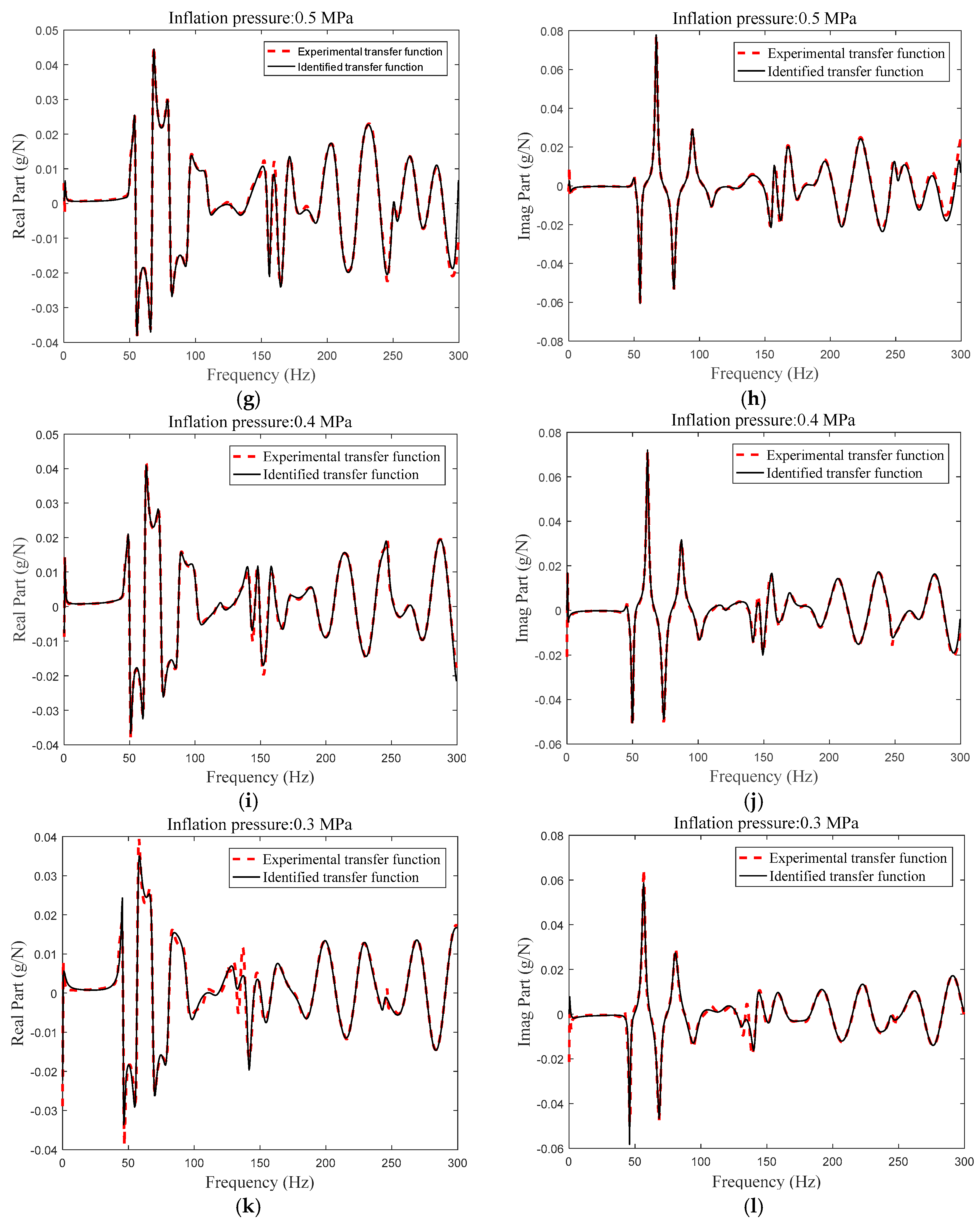
- The errors between the analytical modal frequency with a different inflation pressure (inflation pressure: 0.7, 0.6, 0.5, and 0.4 MPa illustrated in Figure 17) utilizing the flexible ring on an elastic continuous foundation tire model and experimental modal frequency are limited within 3%; meanwhile, the error of analytical modal resonance frequency with inflation pressure of 0.3 MPa is up to 6%; and
- (4)
- The predicted errors utilizing flexible ring on an elastic continuous foundation tire model are less than that utilizing the flexible beam on an elastic continuous beam tire model because of the coupling feature between the radial and tangential deformation of the flexible belt ring and continuous sidewall.
7. Conclusions
Utilizing the theoretical modeling and experimental modal analysis, flexible ring on an elastic continuous foundation tire model is proposed as the two-dimensional tire model to investigate the planar vibration characteristic of the heavy load radial tires with a large flat ratio. The planar coupling feature between the radial and tangential deformations of the flexible belt ring and the continuous sidewall ring is investigated. Additionally, the planar coupling vibration characteristic between the flexible belt ring and the continuous sidewall ring is modeled with a flexible ring on an elastic continuous foundation tire model. Furthermore, modal prediction error of this tire with the normal inflation pressure utilizing the parameters identified can be limited within 3%, and the simplified forms of the flexible ring on an elastic continuous foundation tire model are derived. Additionally, the stiffness variation of the sidewall spring model with respect to the inflation pressure is considered to extend the flexible ring on an elastic continuous foundation tire model. Lastly, structural parameters and the stiffness coefficients, which are sensitive with the inflation pressure, are identified utilizing a genetic algorithm (GA).
To conclude:
- (1)
- Considering the coupling feature of the flexible belt and the continuous sidewall, a flexible ring on an elastic continuous foundation tire models the character of the planar vibration of the heavy load radial tire with a larger flat ratio;
- (2)
- The pre-tension force variations of the flexible belt and the stiffness variations of the two-dimensional sidewall spring model with respect to the inflation pressure are considered and enriched into the flexible ring on an elastic continuous foundation tire model; and
- (3)
- The flexible ring on an elastic continuous foundation tire model with the stiffness variation of the sidewall spring model with inflation pressure can predict the modal frequency of the tires with a different inflation pressure, and the prediction errors of the planar modal frequency of the tires with a different inflation pressure are limited within 3% (inflation pressure: 0.7, 0.6, 0.5, and 0.4 MPa) and 6% (0.3 MPa).
Author Contributions
Q.G. conceived and designed the experiments; Z.L. performed the experiments and analyzed the data; and Z.L. wrote the paper; H.N. analyzed the data and draw the picture.
Funding
This research was funded by National Natural Science Foundation of China grant number [51475462].
Conflicts of Interest
The authors declare no conflict of interest.
References
- Pazooki, A.; Rakheja, S.; Cao, D. Modeling and validation of off-road vehicle ride dynamics. Mech. Syst. Signal Process. 2012, 28, 79–695. [Google Scholar] [CrossRef]
- Cao, R.; Bolton, J.S. Improved Model for Coupled Structural-Acoustic Modes of Tires. SAE Int. 2015, 8, 845–854. [Google Scholar] [CrossRef]
- Iqbal, J.; Zuhaib, K.M.; Han, C.; Khan, A.M. Adaptive Global Fast Sliding Mode Control for Steer-by-Wire System Road Vehicles. Appl. Sci. 2017, 7, 738. [Google Scholar] [CrossRef]
- Bäcker, M.; Gallrein, A.; Roller, M. Noise, vibration, harshness model of a rotating tyre. Veh. Syst. Dyn. 2016, 54, 474–491. [Google Scholar] [CrossRef]
- di Mascio, P.; Loprencipe, G.; Moretti, L. Bridge Expansion Joint in Road Transition Curve: Effects Assessment on Heavy Vehicles. Appl. Sci. 2017, 7, 599. [Google Scholar] [CrossRef]
- Wei, C.; Olatunbosun, O.A. The effects of tyre material and structure properties on relaxation length using finite element method. Mater. Des. 2016, 102, 14–20. [Google Scholar] [CrossRef]
- Besselink, I.J.M.; Schmeitz, A.J.C.; Pacejka, H.B. An improved Magic Formula/Swift tyre model that can handle inflation pressure changes. Veh. Syst. Dyn. 2010, 48, 337–352. [Google Scholar] [CrossRef]
- Mavros, G.; Rahnejat, H.; King, P.D. Transient analysis of tyre friction generation using a brush model with interconnected viscoelastic bristles. Proc. Inst. Mech. Eng. Part K J. Multi-Body Dyn. 2005, 219, 275–283. [Google Scholar] [CrossRef]
- Li, J.; Zhang, Y.; Yi, J. A Hybrid Physical-Dynamic Tire/Road Friction Model. J. Dyn. Syst. Meas. Control 2013, 135, 011007. [Google Scholar] [CrossRef]
- Khosravani, M.R.; Weinberg, K. Characterization of sandwich composite T-joints under different ageing conditions. Compos. Struct. 2018, 197, 80–88. [Google Scholar] [CrossRef]
- Recuero, A.; Serban, R.; Peterson, B.; Sugiyama, H. A high-fidelity approach for vehicle mobility simulation: Nonlinear finite element tires operating on granular material. J. Terramech. 2017, 72, 39–54. [Google Scholar] [CrossRef]
- Huang, D.; Tang, L.; Cao, R. Free vibration analysis of planar rotating rings by wave propagation. J. Sound Vib. 2013, 332, 4979–4997. [Google Scholar] [CrossRef]
- Lee, J.; Wang, S.; Pluymers, B. A modified complex modal testing technique for a rotating tire with a flexible ring model. Mech. Syst. Signal Process. 2015, 60–61, 604–618. [Google Scholar] [CrossRef]
- Krylov, V.V.; Gilbert, O. On the theory of standing waves in tyres at high vehicle speeds. J. Sound Vib. 2010, 329, 4398–4408. [Google Scholar] [CrossRef]
- Vu, T.; Duhamel, D.; Abbadi, Z.; Yin, H.; Gaudin, A. A nonlinear circular ring model with rotating effects for tire vibrations. J. Sound Vib. 2017, 388, 245–271. [Google Scholar] [CrossRef]
- LeBot, A.; Bazari, Z.; Klein, P.; Lelong, J. Statistical analysis of vibration in tyres. J. Sound Vib. 2017, 392, 187–199. [Google Scholar] [CrossRef]
- Matsubara, M.; Tajiri, D.; Ise, T.; Kawamura, S. Vibrational response analysis of tires using a three-dimensional flexible ring-based model. J. Sound Vib. 2017, 408, 368–382. [Google Scholar] [CrossRef]
- Zhou, F.; Yu, T.X.; Yang, L. Elastic behavior of ring-on-foundation. Int. J. Mech. Sci. 2012, 54, 38–47. [Google Scholar] [CrossRef]
- Noga, S.; Bogacz, R.; Markowski, T. Vibration analysis of a wheel composed of a ring and a wheel-plate modelled as a three-parameter elastic foundation. J. Sound Vib. 2014, 333, 6706–6722. [Google Scholar] [CrossRef]
- Liu, Z.; Gao, Q. In-plane vibration response of time and frequency domain with rigid-elastic coupled tire model with continuous sidewall. Proc. Inst. Mech. Eng. Part K J. Multi-Body Dyn. 2017. [Google Scholar] [CrossRef]
- Wang, C.; Ayalewa, B.; Rhyne, T.; Cron, S.; Dailliez, B. Forced in-plane vibration of a thick ring on a unilateral elastic foundation. J. Sound Vib. 2016, 380, 279–294. [Google Scholar] [CrossRef]
- Gong, S. A Study of In-Plane Dynamics of Tires; Faculty of Mechanical Engineering and Marine Technology, Delft University of Technology: Delft, The Netherlands, 1993. [Google Scholar]
- Wei, Y.T.; Nasdalab, L.; Rothert, H. Analysis of forced transient response for rotating tires using REF models. J. Sound Vib. 2009, 320, 145–162. [Google Scholar] [CrossRef]
- Nasiri, S.; Khosravani, M.R.; Weinberg, K. Fracture mechanics and mechanical fault detection by artificial intelligence methods: A review. Eng. Fail. Anal. 2017, 81, 270–293. [Google Scholar] [CrossRef]
- Huang, S.C.; Su, C.K. In-plane Dynamics of Tires on the Road Based on an Experimentally Verified Rolling Ring Model. Veh. Syst. Dyn. 1992, 21, 247–267. [Google Scholar] [CrossRef]
© 2018 by the authors. Licensee MDPI, Basel, Switzerland. This article is an open access article distributed under the terms and conditions of the Creative Commons Attribution (CC BY) license (http://creativecommons.org/licenses/by/4.0/).