Featured Application
The published work can be used for the cleaning of indoor air.
Abstract
In this work, the efficacy of volatile organic compounds (VOCs), such as benzene, toluene, ethylbenzene, and xylene, for the removal of indoor air in a heterogeneous photo-Fenton catalytic semi pilot reactor was investigated at room temperature. Fe-zeolite socony mobil (ZSM)-5 was used as the adsorptive catalytic material, which was coated on the polyethylene tubes as a solid support. The response of Fe-ZSM-5 to UV dry irradiation was investigated in terms of VOC degradation from the indoor air. Different coating materials were tested in order to achieve better binding and less pore blockage. Scanning electron microscope (SEM) micrographs of the Fe-ZSM-5 coated tubes were used for the morphological analysis of the tubes. A complete modular semi pilot reactor (12.51 L) was designed to accommodate the Fe-ZSM-5 coated tubes and UV lamps for UV irradiation, in order to achieve the degradation for VOC and the regeneration of the catalytic material. After completion of the setup, the plant design parameters, such as the linear velocity, surface volume loading rate (SVL), and space retention time (SRT), were calculated.
1. Introduction
Many industries produce gaseous waste, which contains pollutants that are harmful for humans, animals, and the whole environment [1,2]. Furthermore, these pollutants cause a variety of problems. Apart from industries, the creation of almost all building construction and indoor furnishing materials requires an enormous amount of chemicals [3,4]. All of these synthetic materials (from wall paint to nail polish) produce many different volatile organic compounds (VOCs), which act as pollutants. Some of these VOCs, such as benzene, toluene, and their derivatives, are already registered as cancer-causing materials, which are primarily present in our indoor air nowadays [3,5]. The indoor concentrations of several VOCs are 10 times higher than their concentrations outdoors [6].
Therefore, it is very important to remove/reduce these VOCs contaminants in order to guarantee a healthier life [7]. Conventional treatment processes have their drawbacks. Hence, there is a dire need to develop sustainable processes, which have the potential to degrade these organic compounds. Among the modern treatment processes, the advanced oxidation processes (AOPs), such as the photocatalytic process, have already been investigated by several researchers [8,9,10,11]. This photocatalytic process involves a solid phase catalyst composed of a semiconductor material (TiO2, Fe2O3), which is brought into contact with a liquid or gas in the presence of a light source (photon) [12,13,14,15]. The photons that are used to excite the semiconductor material cause the formation of electron–hole pairs, which ultimately leads to the formation of hydroxyl radicals (very reactive species) [14]. These hydroxyl radicals react with and degrade organic compounds. Other processes involve the use of an oxidant (H2O2, O3, or electrical current) as a source of energy in the presence of catalytic materials [16,17]. These processes are called Fenton oxidation or electro-Fenton oxidation [18,19,20]. All previous studies used an oxidant or continuous energy for oxidation when interacting with pollutants, which means that they all used homogenous processes. The uniform dispersion of the catalyst plays a vital role in permitting better catalytic activity [21]. Many researchers have tried several ways to homogeneously disperse catalysts on the solid supports [22,23,24,25,26].
In our previous studies, we demonstrated a heterogeneous photo-Fenton process by incorporating Fe2O3 on zeolite socony mobil (ZSM)-5 [27,28]. The main idea was to simultaneously utilize the porous adsorption qualities of ZSM-5 and its ability to be a semi-conductor, as well as Fenton’s reagent properties of iron. The formed Fe-ZSM-5 was pre-irradiated with UV light and was applied for the removal of VOCs from air for the first time. The process showed a good regeneration ability and a high efficiency in the laboratory at batch scale.
In the present study, we tried to implement the same idea on a semi pilot scale, with the aim of scaling up the technology for commercial use. For this purpose, (1) the Fe-ZSM-5 zeolite material was coated on the polyethylene tubes; (2) a modular reactor was designed to hold most of the catalyst coated tubes; (3) the modular reactor tubes were irradiated with UV lamps; (4) the reactor design parameters, such as linear velocity, surface loading rate (SLR), and surface retention time (SRT), were measured; and (5) finally, the plant was operated for six cycles so as to test its degradation and recyclability. Since the whole work was done on pilot scale, only the total removal of the VOCs was considered, rather than finding the exact % of adsorption and catalysis, although the used material has both properties.
2. Experimental
2.1. Materials
Benzene, toluene, ethylbenzene, and xylene (BTEX) (50 µmol/mol stabilized in N2) were purchased from Nano-Gas, Korea, and were used as supplied, without further treatment. The Fe-ZSM-5 was prepared in the lab according to the previously described procedure [29,30]. The polyethylene woven tubes were purchased from Dae A. Co., Korea. The ethyl vinyl acetate (EVA) (Okong Co., Seoul, Korea) and polyethyl vinyl alcohol (PVA) (Hyung Je Co., Busan, Korea) binders were supplied by local companies of Korea. The epoxy (resin) and catalyst (amine as the hardener) were purchased from Dong Yang Epoxy, Korea. All of the coating materials were of commercial grade and locally available. The UV lamps were purchased from Philips, Korea.
2.2. Coating of Fe-ZSM-5 on Polyethylene Tubes
The Fe-ZSM-5 powdered catalytic material was coated on the polyethylene woven tubes using two different methods. Firstly, the Fe-ZSM-5 was dissolved in EVA and PVA solutions, at different dilution ratios, with ethanol. The slurry of the binder and catalyst was coated on the tubes using the dip method, at a speed of 2 cm/s. The second method involved the application of a thin film of epoxy (at a different mixing ratio with the catalyst) on the surface of tubes, before Fe-ZSM-5 was sprayed on the thin epoxy layer on the polyethylene tube. Different ratios were applied and characterized by SEM, in terms of uniform dispersion and perfect support for the maximum surface area.
2.3. VOCs Adsorption Test on Coated Tubes
Before designing the reactor, it was important to study the adsorption capacity of the catalyst coated tubes at a laboratory scale. For this purpose, four adsorption tests were performed. In the first test, 10 cm of the bare tube (polypropylene woven) was placed into a Tedlar bag, before 3 L of BTEX (50 µmol/mol) was added. The variation of concentration with respect to time was measured, as previously described [21]. The second and third tests were performed in a similar way, using the epoxy coated tube and the Fe-ZSM-5 coated (with epoxy) tubes. In the last test, the effect of UV irradiation on the Fe-ZSM-5 coated tubes was studied using the same parameters as for the first three tests. Before the introduction of a catalyst coating to the Tedlar bag, it was irradiated with UV for 30 min. The UV irradiation setup for this single tube was the same as described in the work published by Aziz and Kim. They described that “first, the catalysts were irradiated with UV heterogeneously before application to BTEX oxidative removal as discussed in introduction the developed process is catalytic dry oxidation. The catalytic material was pre heated at 105 °C for 24 h in an air circulated oven to remove moisture if any. The quartz sample holder for catalyst was irradiated by four UV lamps (4 W, 254 nm, Zhejiang Yaguang Technology Co., Ltd., Wenzhou, Zhejiang, China) fitted at each corner of the setup at room temperature for different time interval ranging. The light sources 4 cm away from the sample holder. We directly removed the catalyst after irradiation and used for the removal of VOCs. Secondly, the above irradiated samples were applied for oxidation of BTEX in batch experiments” [28].
2.4. Semi Pilot Reactor Design and Setup
The rectangular semi pilot reactor was designed in a modular form, which is shown in Figure 1. It consists of six rectangular plastic boxes with two sides that are open. The width and length of each box is 14 cm. The tubes with the coating of the catalyst medium, Fe-ZSM-5, are installed in each module, in the space between the two rows. UV lamps are installed in the fixed space that is located outside of these tubes, which can be seen in Figure 1. Once a box (single module) is ready, it is connected to another box to form a semi pilot reactor with a length of 62 cm. The different parameters of the reactor are given in Table 1.
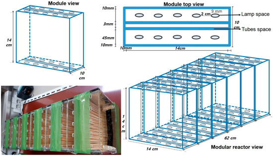
Figure 1.
Modular design with the partially prepared actual plant, which shows that the tubes fit in the designed spaces.

Table 1.
Dimensions of proposed semi pilot plant.
UV lamps with a tube length of 14 cm are placed inside the module at a certain position and spot. The emission spectrum of these lamps has a wavelength of 254 nm. The intensity of the UV that reaches the surface of the Fe-ZSM-5 coated tubes was not measured, although the power of the lamps was 4 W. The fully operational semi pilot reactor is shown in Figures S1 and S2.
2.5. Measurement of VOCs
The efficiency of the removal of VOCs during each experiment with the above setup was calculated using the average concentrations of each component in the inlet, center, and the outlet gas of the reactor, with respect to time and flow rate, according to the examined parameters. The concentration of VOCs in the air was analyzed using the same procedure as mentioned previously in a study. In more detail, “the VOCs and CO2 concentrations were monitored by using an Ultra Trace GC coupled with a mass spectrometer from Thermo-Scientific. The stainless-steel (SS) coupling tube was maintained at 220 °C between GC and MS. A 250 µL sample with sampling syringe was used for all measurements. The presence of reaction products during the removal reaction was noted by the evolution of the respective m/z peaks of those molecules. VOC (Toluene, ethylbenzene) and CO2 removal values were calculated according the following equation, the same as mentioned in our previous studies.
whereas, x is benzene, toluene, ethylbenzene, and xylene” [21].
2.6. Design Parameters
The surface area loading rate is a hydraulic loading factor that measures the flow rate per surface area of the adsorbent/catalyst. This factor was commonly used to represent the flow rate of liquids per surface area of the solid packing materials in the reactor. However, we used the same factor to represent the flow of gas through the catalyst, which is supported on the tubes. Mathematically, the SLR is expressed as follows:
The surface retention time (SRT), which is also sometimes called the detention time (DT), is the theoretical time that a VOC is held in the reactor. This factor is based on the flow rate and volume of the reactor [31]. Mathematically, it is computed as follows:
3. Results and Discussion
3.1. Coating of Fe-ZSM-5 on Polymeric Woven Tubes
Different binding materials were applied for coating the Fe-ZSM-5 powder on the polyethylene tubes. Of these materials, we only discussed the binding materials that showed considerable results. Ethyl vinyl acetate (EVA) and poly vinyl alcohol (PVA) with different ratios of ethanol were applied, although EVA has not been presented (not shown).
Furthermore, PVA has better binding than EVA, and the epoxy coatings are displayed in Figure 2, which allows for a comparison in terms of binding. From the SEM images of coatings and the TGA analysis (Figure S3), it is evident that PVA is not as good as the epoxy coating material, because the ZSM-5 particles were submerged completely in the PVA coated tubes and lost their characteristics. Therefore, only the epoxy was further studied with different mixing ratios of the catalyst (hardener), which is shown in Figure 3. These micrographs demonstrated that the 1:1 ratio of epoxy and catalyst is better (as Fe-ZSM-5 morphology is visible, which shows that it is firmly attached on the tubes), which will be used for coating materials in the next few studies.
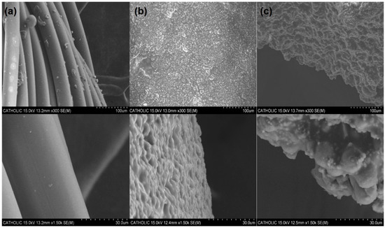
Figure 2.
SEM images (100 and 30 microns) of Fe-zeolite socony mobil (ZSM)-5 coated tubes with different coating materials, namely: (a) bare tube, (b) polyethyl vinyl alcohol (PVA) + Fe-ZSM-5 tube, and (c) epoxy + Fe-ZSM-5 tube.
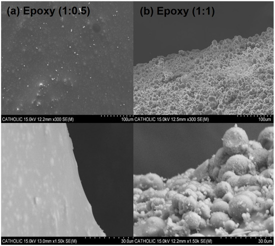
Figure 3.
SEM images of coated tubes at 100 and 30 microns with different compositions of binder and catalyst with same amount of Fe-ZSM-5 catalyst.
3.2. VOC Removal on Tubes
As a sample control study, the bare and epoxy coated tubes were used for the adsorption of BTEX at the batch scale. Similarly, the Fe-ZSM-5 coated tubes were also tested for the adsorption of VOCs as well as their degradation by UV irradiation. The results in Figure 4 show that the bare polyethylene tubes did not adsorb the VOCs at all, while the epoxy coated tube increased the concentration of the VOCs with time, which was expected. As the coating was created by organic solvents (mentioned in the Section 2 in detail), this became another source of VOCs, after a certain amount of time. Testing of the catalyst coated tube showed the same adsorption behavior with and without UV, which involved the adsorption of BTEX by the powdered form of the catalyst. This outcome has already been reported. Therefore, from Figure 2, it can be inferred that the tubes do not contribute to the adsorption of VOCs, as it showed an adverse effect instead. Therefore, any adsorption that occurred in the catalyst coated tube was merely due to the effect of Fe-ZSM-5. Hence, we proved that the Fe-ZSM-5 coated tubes are useful for VOC removal, and we subsequently moved to designing the reactor.
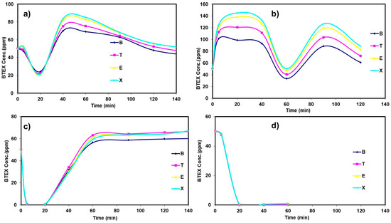
Figure 4.
Benzene, toluene, ethylbenzene, and xylene (BTEX) concentrations with respect to time for 10 cm/3 L of 50 ppm BTEX, namely: (a) bare tube, (b) just epoxy coated tube, (c) epoxy + Fe-ZSM-5 tube, and (d) epoxy + Fe-ZSM-5 + UV (30 min).
3.3. Semi Pilot Plant Operation: Linear Velocity Optimization
In order to study the design parameters of the semi pilot reactor (Figures S1 and S2), which were completely coupled with UV lamps, the linear velocity was first optimized. For this purpose, the reactor was connected with a BTEX cylinder (50 µmol/mol) with a pressure of 10 atm. The mixture of VOCs passed through the reactor as a result of the intrinsic pressure of the storage cylinder. Three sampling ports were used to withdraw the sample at different times. The linear velocity was measured at the outlet of the reactor, with the help of a portable flow meter probe. For each port, an air suction pump was used to gather the representative sample. The BTEX concentrations were measured at linear velocities of 1, 3.5, and 5 cm/s for optimum flow and for maximum adsorption. Figure 5 shows the proportion removed (%) for all four components using different experimental linear velocities at three points (inlet, center, and outlet) of the reactor.
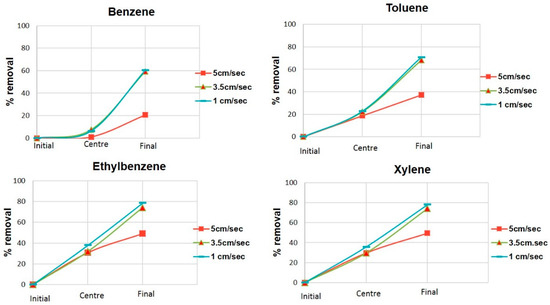
Figure 5.
Linear velocity optimization for the semi pilot reactor with an inlet concentration of 50 ppm and a running time of 3 min for each velocity.
Although the removal efficiency is different with different components at the center and different outlets for all three of the velocities, 3.5 cm/s was found to be the optimal highest velocity needed in order to guarantee a high removal rate. We compared the removal of VOCs at 1 and 3.5 cm/s. We found that a linear velocity of 5 cm/s reduced the removal by almost 20% compared with the velocity of 3.5 cm/s. This can be explained by the ability to have a low interaction time (retention time) for the gases to react with an active surface area at a high linear velocity. Therefore, based on the findings of this experiment (Figure 5), we will use a linear velocity of 3.5 cm/s for the VOCs passing through the reactor.
3.4. Blank Test of Semi Pilot Reactor
In the above section, we demonstrated the effect of linear velocity on the proportion of VOCs removed with a running time of 3 min at each velocity. After this, we studied the removal capacity of the reactor without the application of UV for a total time of 60 min at the optimum linear velocity of 3.5 cm/s. This test is a blank test for a semi pilot reactor, which means that all of the systems are functional only if the UV lamps are off, as our hypothesis was based on the fact that UV irradiation helps to remove VOCs. We observed outstanding results, which are shown in Figure 6. The outgoing gas was monitored for BTEX at time intervals of 3, 5, 10, 20, 30, 45, and 60 min. As expected, the BTEX was removed gradually and showed a minimum removal at 60 min. Moreover, the total VOC removal was calculated at the inlet and outlet of the semi pilot reactor instead of measuring the adsorption parameters and the conversion ratio to CO2 (catalysis), although, it was not the scope of study.
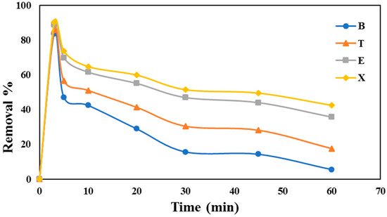
Figure 6.
Blank test of the semi pilot reactor without the application of UV.
3.5. Effect of UV Light on the Removal of VOCs
In the previous section, we discussed the breakthrough of the semi pilot reactor without the use of UV irradiation. In this section, the effect of the UV treatment on the cyclic use of the reactor was evaluated. In this experiment, the reactor catalysts were activated by UV irradiation for 45 min (this was 30 min for a batch in order to be on the safe side due to the small lamp sizes), which was followed by BTEX flow for 5 min at the optimum linear velocity of 3.5 cm/s. This process was repeated six times, and the results are displayed in Figure 7. This shows the results of the samples taken at the outlet of the reactor after 1, 3, and 5 min of continuous flow of VOCs. The results of the samples taken at the center of the reactor are shown in Figure S4. From Figure 7, we observed that the efficiency of the removal of VOCs during cycles 1–6 remained constant at more than 75% for xylene and ethylbenzene. This proportion of VOCs that are removed are reduced to be less than 50% in the case of Figure 6, where there was no UV applied. Similarly, the removal efficiency of the components of the VOCs, such as toluene and benzene, varied from 40–58% and 30–38% for cycles 1–6, respectively, as shown in Table 1. Although these efficiencies are lower than the other two components, they are still higher than in Figure 6, which has lower values of 20% and 8%, respectively. Another interesting point that was observed in this experiment, was that the VOC components followed an order of X > E > T > B, which is different from previous findings (E > T > B > X) [21]. This behavior is possibly due to the coating, which altered the morphology and pore sizes of the catalytic material, Fe-ZSM-5. Apart from the different removal order, we found strong evidence that the UV-pretreatment coupled system is capable of the sustainable removal of VOCs from air. In our system, the VOCs removal is not a single process, it is adsorptive catalysis. First, VOCs are trapped in the pores of ZSM-5, and then the interaction of UV with Fe present in the structure of ZSM-5 initiates’ oxidation, which ultimately ends at the degradation of VOCs, which is catalysis. We have not studied the actual ratio between adsorption and catalysis, as it is truly very hard to distinguish between adsorption and catalysis. However, in our previous studies [21,28], we reported evidence that VOCs were first adsorbed, as the base material is porous, followed by catalytic degradation. Furthermore, our study purpose was more related to total removal, rather than finding the scientific ratio between adsorption and catalysis, as the developed system is at semi pilot scale. Moreover, the authors have the opinion that in the developed system, it is also “adsorptive catalytic oxidation” instead of adsorption or only catalysis. Furthermore, in our study, we used 50 µmol/mol of BTEX, which is a very high concentration. The obtained results were compared with other materials in Table S1. However, in the real-life scenario, these concentrations can only be in the range of 0.1–2.0 µmol/mol. Therefore, the presented system can be used for an extended period of time in real life.
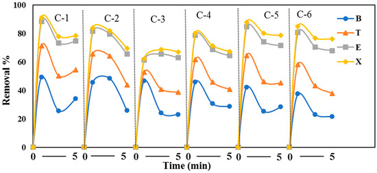
Figure 7.
The cyclic use of the semi pilot plant with the application of coupled UV for a running time of 5 min at an inlet concentration of 50 ppm with six cycles.
3.6. Surface Area Loading Rate (SLR) and Surface Retention Time (SRT)
The design parameters were calculated based on the experimental data, and the values of SLR and SRT are 69.13 L/min/m2 and 0.295 min, respectively, at a linear (optimum) velocity of 3.5 cm/s.
4. Conclusions
We concluded that the VOC removal efficiency was remarkably enhanced by the use of the UV coupled system and the presence of the catalyst coating on the polypropylene tubes, which is a first in open source literature. This proved that the proposed semi pilot plant system was workable. Regarding the operation parameters, using the optimal flow rate of 3.5 cm/s for VOCs passing through the reactor, the SLR of 69.13 L/min/m2 and SRT of 0.295 min were calculated. The system was tested for six cycles, and the efficiency remained the same for two components (xylene and ethylbenzene). Although the efficiency decreased for the other two components (benzene and toluene), it was still significantly higher than the breakthrough experiment, which proved the sustainable applicability of the developed system for long-term use.
Supplementary Materials
The following are available online at http://www.mdpi.com/2076-3417/8/10/1920/s1, Figure S1: Reactor module, with and without lamps, Figure S2: Complete semi pilot plant with lamps on and off respectively, Figure S3: TGA results of bare and epoxy coated tubes, Figure S4: BTEX removal (%) at the center of semi pilot plant after being irradiated with UV. The experiment was run for 6 cycles. The BTEX concentration was 50 ppm, while the flow rate was 3.5 cm/s with a total running time of 60 minutes, Figure S5: Removal (%) of BTEX with respect to time for one module installed in the closed chamber, Table S1: Data at outlet (% Removal Efficiency).
Author Contributions
Conceptualization, K.S.K. and A.A.; Experimental work, A.A., S.K. and M.S.; Writing Original Draft, A.A. and M.S., Writing-Review, A.A. and M.S.; Supervision, Funding Acquisition and Project Administration, K.S.K.
Funding
This research was funded by Korea Institute of Civil Engineering and Building Technology (KICT) under grant number 20180101-001 and The APC was funded by [KICT].
Conflicts of Interest
The authors declare no conflict of interest. The funders had no role in the design of the study; in the collection, analyses, or interpretation of data; in the writing of the manuscript, and in the decision to publish the results.
Acronyms
| ZSM-5 | zeolite socony mobil-5 |
| Fe-ZSM-5 | iron zeolite socony mobil-5 |
| VOCs | volatile organic compounds |
| BTEX | benzene, toluene, ethylbenzene, and xylene |
| SLR | surface loading rate |
| SRT | surface retention time |
References
- Li, J.; He, H.; Hu, C.; Zhao, J. The abatement of major pollutants in air and water by environmental catalysis. Front. Environ. Sci. Eng. 2013, 7, 302–325. [Google Scholar] [CrossRef]
- Qu, F.; Zhu, L.; Yang, K. Adsorption behaviors of volatile organic compounds (VOCs) on porous clay heterostructures (PCH). J. Hazard. Mater. 2009, 170, 7–12. [Google Scholar] [CrossRef] [PubMed]
- Zhao, W.; Dai, J.; Liu, F.; Bao, J.; Wang, Y.; Yang, Y.; Yang, Y.; Zhao, D. Photocatalytic oxidation of indoor toluene: Process risk analysis and influence of relative humidity, photocatalysts, and VUV irradiation. Sci. Total Environ. 2012, 438, 201–209. [Google Scholar] [CrossRef] [PubMed]
- Wang, S.; Ang, H.M.; Tade, M.O. Volatile organic compounds in indoor environment and photocatalytic oxidation: State of the art. Environ. Int. 2007, 33, 694–705. [Google Scholar] [CrossRef] [PubMed]
- Ge, J.; Choi, N. Fabrication of functional polyurethane/rare earth nanocomposite membranes by electrospinning and its VOCs absorption capacity from air. Nanomaterials 2017, 7, 60. [Google Scholar] [CrossRef] [PubMed]
- Weisel, C.P.; Alimokhtari, S.; Sanders, P.F. Indoor air VOC concentrations in suburban and rural New Jersey. Environ. Sci. Technol. 2008, 42, 8231–8238. [Google Scholar] [CrossRef] [PubMed]
- Yang, D.S.; Pennisi, S.V.; Son, K.-C.; Kays, S.J. Screening indoor plants for volatile organic pollutant removal efficiency. HortScience 2009, 44, 1377–1381. [Google Scholar]
- Ikhlaq, A.; Brown, D.R.; Kasprzyk-Hordern, B. Mechanisms of catalytic ozonation on alumina and zeolites in water: Formation of hydroxyl radicals. Appl. Catal. B Environ. 2012, 123–124, 94–106. [Google Scholar] [CrossRef]
- Zhong, L.; Haghighat, F.; Lee, C.-S.; Lakdawala, N. Performance of ultraviolet photocatalytic oxidation for indoor air applications: Systematic experimental evaluation. J. Hazard. Mater. 2013, 261, 130–138. [Google Scholar] [CrossRef] [PubMed]
- Zhong, L.; Haghighat, F. Photocatalytic air cleaners and materials technologies—Abilities and limitations. Build. Environ. 2015, 91, 191–203. [Google Scholar] [CrossRef]
- Zhong, L.; Brancho, J.J.; Batterman, S.; Bartlett, B.M.; Godwin, C. Experimental and modeling study of visible light responsive photocatalytic oxidation (PCO) materials for toluene degradation. Appl. Catal. B Environ. 2017, 216, 122–132. [Google Scholar] [CrossRef] [PubMed]
- Takeuchi, M.; Hidaka, M.; Anpo, M. Efficient removal of toluene and benzene in gas phase by the TiO2/Y-zeolite hybrid photocatalyst. J. Hazard. Mater. 2012, 237–238, 133–139. [Google Scholar] [CrossRef] [PubMed]
- Gallastegi-Villa, M.; Aranzabal, A.; González-Marcos, J.A.; González-Velasco, J.R. Metal-loaded ZSM5 zeolites for catalytic purification of dioxin/furans and NOx containing exhaust gases from MWI plants: Effect of different metal cations. Appl. Catal. B Environ. 2016, 184, 238–245. [Google Scholar] [CrossRef]
- Huang, Y.; Ho, S.; Lu, Y.; Niu, R.; Xu, L.; Cao, J.; Lee, S. Removal of indoor volatile organic compounds via photocatalytic oxidation: A short review and prospect. Molecules 2016, 21, 56. [Google Scholar] [CrossRef] [PubMed]
- Mamaghani, A.H.; Haghighat, F.; Lee, C.-S. Photocatalytic oxidation technology for indoor environment air purification: The state-of-the-art. Appl. Catal. B Environ. 2017, 203, 247–269. [Google Scholar] [CrossRef]
- Wang, W.; Zhang, K.; Yang, Y.; Liu, H.; Qiao, Z.; Luo, H. Synthesis of mesoporous Al2O3 with large surface area and large pore diameter by improved precipitation method. Microporous Mesoporous Mater. 2014, 193, 47–53. [Google Scholar] [CrossRef]
- Li, R.; Jia, Y.; Bu, N.; Wu, J.; Zhen, Q. Photocatalytic degradation of methyl blue using Fe2O3/TiO2 composite ceramics. J. Alloys Compd. 2015, 643, 88–93. [Google Scholar] [CrossRef]
- Tokumura, M.; Nakajima, R.; Znad, H.T.; Kawase, Y. Chemical absorption process for degradation of VOC gas using heterogeneous gas–liquid photocatalytic oxidation: Toluene degradation by photo-Fenton reaction. Chemosphere 2008, 73, 768–775. [Google Scholar] [CrossRef] [PubMed]
- Özcan, A.; Atılır Özcan, A.; Demirci, Y.; Şener, E. Preparation of Fe2O3 modified kaolin and application in heterogeneous electro-catalytic oxidation of enoxacin. Appl. Catal. B Environ. 2017, 200, 361–371. [Google Scholar] [CrossRef]
- Lv, Q.; Li, G.; Lu, H.; Cai, W.; Huang, H.; Cheng, C. Preparation of magnetic zeolite γ-Fe2O3/TS-1 with core/shell structure and application in photocatalytic degradation. Microporous Mesoporous Mater. 2015, 203, 202–207. [Google Scholar] [CrossRef]
- Aziz, A.; Kim, S.; Kim, K.S. Fe/ZSM-5 zeolites for organic-pollutant removal in the gas phase: Effect of the iron source and loading. J. Environ. Chem. Eng. 2016, 4, 3033–3040. [Google Scholar] [CrossRef]
- Polshettiwar, V.; Cha, D.; Zhang, X.; Basset, J.M. High-surface-area silica nanospheres (KCC-1) with a fibrous morphology. Angew. Chem. Int. Ed. 2010, 49, 9652–9656. [Google Scholar] [CrossRef] [PubMed]
- Tempelman, C.H.L.; De Rodrigues, V.O.; Van Eck, E.R.H.; Magusin, P.C.M.M.; Hensen, E.J.M. Desilication and silylation of Mo/HZSM-5 for methane dehydroaromatization. Microporous Mesoporous Mater. 2015, 203, 259–273. [Google Scholar] [CrossRef]
- Bazyari, A.; Khodadadi, A.A.; Haghighat Mamaghani, A.; Beheshtian, J.; Thompson, L.T.; Mortazavi, Y. Microporous titania–silica nanocomposite catalyst-adsorbent for ultra-deep oxidative desulfurization. Appl. Catal. B Environ. 2016, 180, 65–77. [Google Scholar] [CrossRef]
- Blanch-Raga, N.; Palomares, A.E.; Martínez-Triguero, J.; Valencia, S. Cu and Co modified beta zeolite catalysts for the trichloroethylene oxidation. Appl. Catal. B Environ. 2016, 187, 90–97. [Google Scholar] [CrossRef]
- Chlala, D.; Giraudon, J.M.; Nuns, N.; Lancelot, C.; Vannier, R.-N.; Labaki, M.; Lamonier, J.F. Active Mn species well dispersed on Ca2+ enriched apatite for total oxidation of toluene. Appl. Catal. B Environ. 2016, 184, 87–95. [Google Scholar] [CrossRef]
- Aziz, A.; Park, H.; Kim, S.; Kim, K.S. Phenol and ammonium removal by using Fe-ZSM-5 synthesized by ammonium citrate iron source. Int. J. Environ. Sci. Technol. 2016, 13, 2805–2816. [Google Scholar]
- Aziz, A.; Kim, K.S. Synergistic effect of UV pretreated Fe-ZSM-5 catalysts for heterogeneous catalytic complete oxidation of VOC: A technology development for sustainable use. J. Hazard. Mater. 2017, 340, 351–359. [Google Scholar] [CrossRef] [PubMed]
- Aziz, A.; Kim, S.; Kim, K.S. Heterogeneous oxidation of organics from wastewater: Fe-ZSM-5 prepared by different silicon sources. Desalin. Water Treat. 2017, 58, 385–390. [Google Scholar] [CrossRef]
- Aziz, A.; Kim, K. Investigation of tertiary butyl alcohol as template for the synthesis of ZSM-5 zeolite. J. Porous Mater. 2015, 22, 1401–1406. [Google Scholar] [CrossRef]
- Scott Fogler, H. Elements of Chemical Reaction Engineering, 4th ed.; Prentice Hall PTR: Upper Saddle River, NJ, USA, 2005; ISBN 0-13-047394-4. [Google Scholar]


© 2018 by the authors. Licensee MDPI, Basel, Switzerland. This article is an open access article distributed under the terms and conditions of the Creative Commons Attribution (CC BY) license (http://creativecommons.org/licenses/by/4.0/).