Article

The Seepage and Stability Performance Assessment of a New Drainage System to Increase the Height of a Tailings Dam

1
State Key Laboratory of Hydrology-Water Resources and Hydraulic Engineering, Hohai University, Nanjing 210098, China
2
The College of Water Conservancy and Hydropower Engineering, Hohai University, Nanjing 210098, China
*
Author to whom correspondence should be addressed.
Appl. Sci. 2018, 8(10), 1840; https://doi.org/10.3390/app8101840
Submission received: 4 September 2018 / Revised: 1 October 2018 / Accepted: 4 October 2018 / Published: 7 October 2018
(This article belongs to the Section Environmental Sciences)

Abstract

:

Featured Application

The proposed drainage system has potential applications to improve seepage and slope stability for the similar engineering.

Abstract

Effective methods for extending the storage capacity of tailings for a mining company include expanding and increasing the height of the tailings dam. However, this change could lead to an uplift in the phreatic line and a decrease in the slope stability. In this paper, a new drainage system combining a horizontal drainage pipe with an upward bending slotted pipe was proposed and applied to the design of a seepage-proof system for the Xigou tailings dam with an increased height. To accurately simulate the performance of the seepage control system, a three-dimensional finite element model was established on the basis of a geological investigation of the site conditions. In this work, a substructure technique was used to model the drainage pipe with a small radius and dense spacing to reduce the difficulty in mesh generation, and a back-analysis method called MPSO-BP (modified particle swarm optimization algorithm and a back propagation neural network) was used to correct the measured permeability coefficients. The results show that the new drainage system can effectively dissipate the seepage pressure, decrease the phreatic surface, and improve the safety factors of the slope stability. The proposed drainage system can also meet the seepage stability requirements of the higher tailings dam. Additionally, this system can be widely deployed in similar projects.

1. Introduction

A tailings dam is a large-scale, man-made structure that is constructed worldwide to keep waste tailings away from ongoing mining activities where tailing are mixtures of crushed rocks [1]. Waste tailings pose a potential hazard to communities and ecosystems near mining areas [2]. The upstream construction method is the main method for raising tailings dams [3]. Currently, in China, there are 14,000 tailings dams (in operation, inactive, and abandoned), and more than 90% of these dams are constructed using the upstream method [4]. In the raising method, dikes are sequentially constructed on the previously deposited tailings, which may be present in a saturated and loose state. The saturated tailings uplift the phreatic surface, which is usually called the “lifeline” of the tailings dam, and cause an increase in the pore water stresses in the saturated zone [5]. Therefore, the effective stresses are reduced, which could lead to slope instability. Over the past few decades, tailings dams that have undergone failure have caused serious disasters and have drawn public attention regarding the safety of tailings construction and management [6,7]. Various factors usually contribute to the failure of a tailings dam, such as extreme events, foundation failure, overtopping, poor operational and management practices, or a combination of these factors [8,9,10,11]. Seepage and a rise in the phreatic surface are related to 30%–40% of the failures of tailings ponds [12].
Currently, tighter legislation and regulations on tailings disposal have forced the mining industry to address the disposal of a vast quantity of highly visible waste originating from mining activities [13,14]. Because suitable land for tailings dams is increasingly rare and expensive in a developing economy, to reduce costs, the mining industry prefers to expand and increase the height of tailings ponds instead of constructing a new tailings dam [15]. Increasing the height of a tailings dam to extend its tailings storage capacity is very common in China’s mines [16]. However, this change could lead to an increase in the phreatic surface, causing the original drainage system to no longer meet the requirements of seepage and consolidation after increasing the dam height, thus decreasing the stability of the tailings dams [17,18]. Hence, a comprehensive analysis of the new drainage system is essential before the structure is applied to increase the height of an existing tailings dam [19].
The drainage facilities of a tailings dam are complex, and the accurate simulation of the drainage behavior is a technical problem in seepage calculations. The research on the seepage capacity of a drainage pipe is mainly divided into theoretical research and numerical simulations. For theoretical research, by analyzing the structure and permeability of the drainage pipe, Fu et al. [20] affirmed the seepage capacity of the embedded drainage pipe. Jin et al. [21] proposed a formulation for calculating the total seepage discharge and obtained the equivalent radius of the filter layer by establishing a theoretical calculation model of the drainage pipe system. For numerical simulations, finite element analysis of a draining pipe remains a challenge [22,23]. The major cause of this problem can be attributed to two factors. The first factor is the difficulty of generating the finite element mesh with hundreds or even thousands of drainage pipes with small diameters and dense spacing, and the second factor is the strong nonlinearity in the calculation of the phreatic surface. To avoid these difficulties, an equivalent medium producing the same flow rate was proposed to model the drainage pipe. At the same time, many new techniques were developed for simulating the seepage behavior of the drainage system, such as a substructure technique, a point well model, a semianalytical approach, or composite element methods [24,25,26]. However, except when using the substructure technique, it is difficult to accurately impose the boundary conditions of the drainage facilities in most of the numerical simulation models; thus, the theoretical strictness of the solutions, to some degree, is not guaranteed [27]. In this paper, the boundary condition of a sub-element for the drainage pipes satisfies Signorini’s complementary condition. In addition, the substructure technique can essentially overcome the singularity at the seepage points and maintain mesh independency.
In this study, to effectively increase the seepage capability, a new drainage system including horizontal pipes and upward bending slotted pipes is proposed. Compared with traditional drainage systems, the proposed system has both a reasonable layout method and a strong seepage capability, which can effectively reduce the water level in the dam slope. Then, the finite element analyses of the seepage flow behavior of the proposed drainage method are introduced using a model combining the substructure technique with the variational inequality formulation of Signorini’s type [28]. There are plans to expand the storage capacity of the Xigou tailings dam, which is located in Hubei Province in central China (Figure 1); this dam is taken as a case study example. The remainder of this study is arranged as follows: in Section 3, background information about the tailings pond at the Xigou mine is collected, including geological characterization and the seepage control system. Section 4 presents the performance of the new drainage method by a three-dimensional numerical model of the Xigou tailings dam and demonstrates the effectiveness of the proposed drainage method, which is followed by a dam stability assessment using the limit equilibrium method (LEM) in Section 5. In the final section, conclusions are drawn.

2. A New Drainage Method for the Tailings Pond
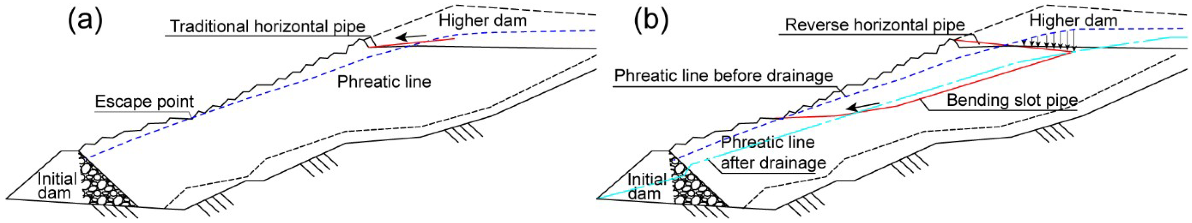
2.1. Layout Method

When the height of the dam is increased, the phreatic surface in the tailings dam slope is inevitably raised. Therefore, to increase the slope stability, a seepage control system in the embankment must be proposed and implemented to accelerate the dissipation of excess pore water stresses and to lower the phreatic surface in the downstream shell of the tailings dam. As shown in Figure 2a, the traditional arrangement method uses an upwardly inclined drainage pipe, taking into account that the seepage can quickly flow out and that an uneven settlement can be weakened during the disposal of waste ore. However, this method has a fatal shortcoming. In this case, when the drainage pipes are almost parallel to the phreatic line, the seepage stops. Even worse, the drainage pipe is then vulnerable to blockage and failure. To solve the shortcoming in the traditional method, Figure 2b presents a new arrangement of the drainage pipe based on many investigations and analyses of tailings ponds. A horizontal drainage pipe combined with an upward bending slotted pipe, which is inserted into the phreatic line at a certain depth, is proposed. When this arrangement is applied to a tailings dam with an increased height, the phreatic surface intersects the drainage pipe. This arrangement contributes to the seepage of water, which is centrally discharged out of the embankment along the drainage structure, significantly improving the drainage capacity.

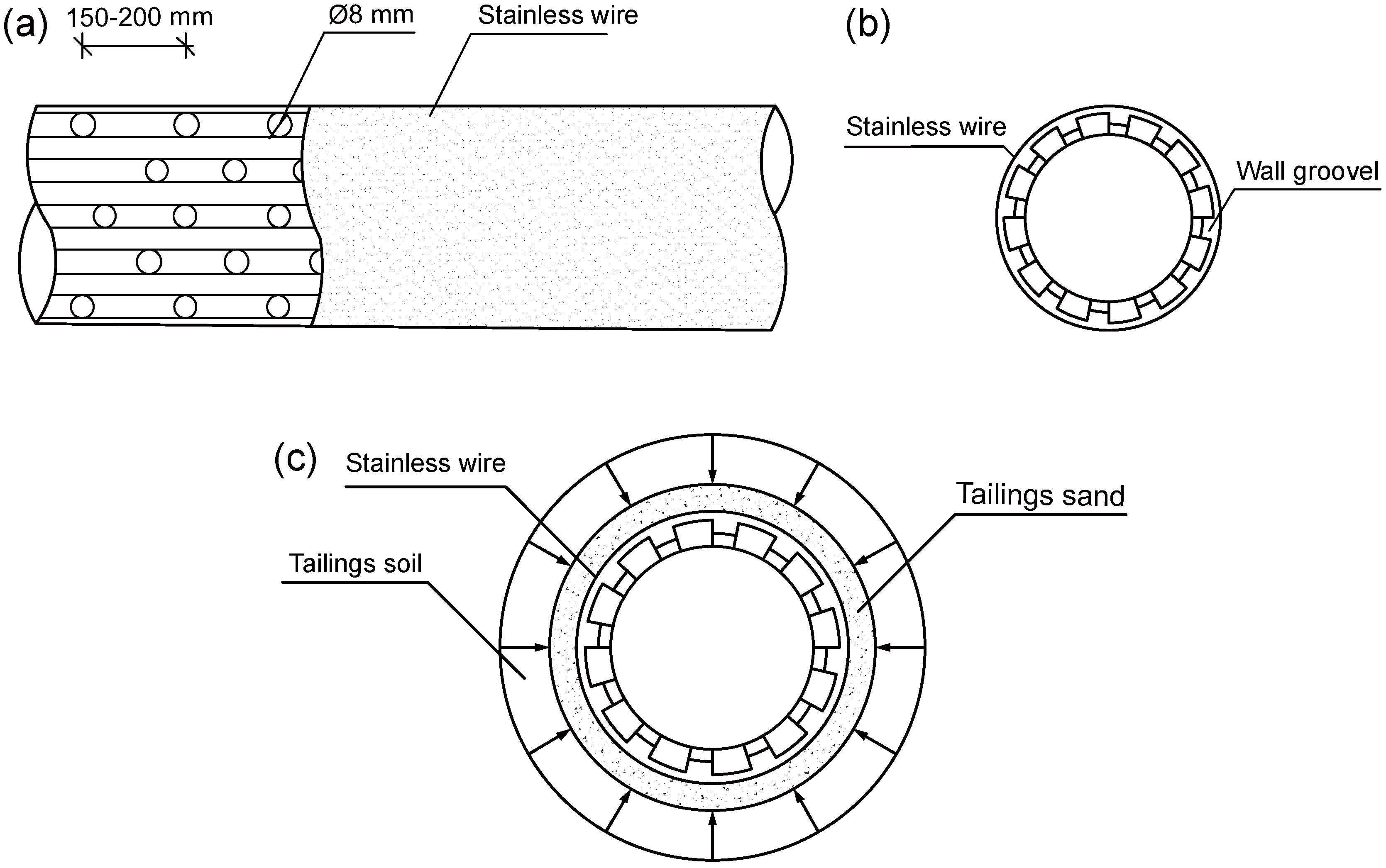
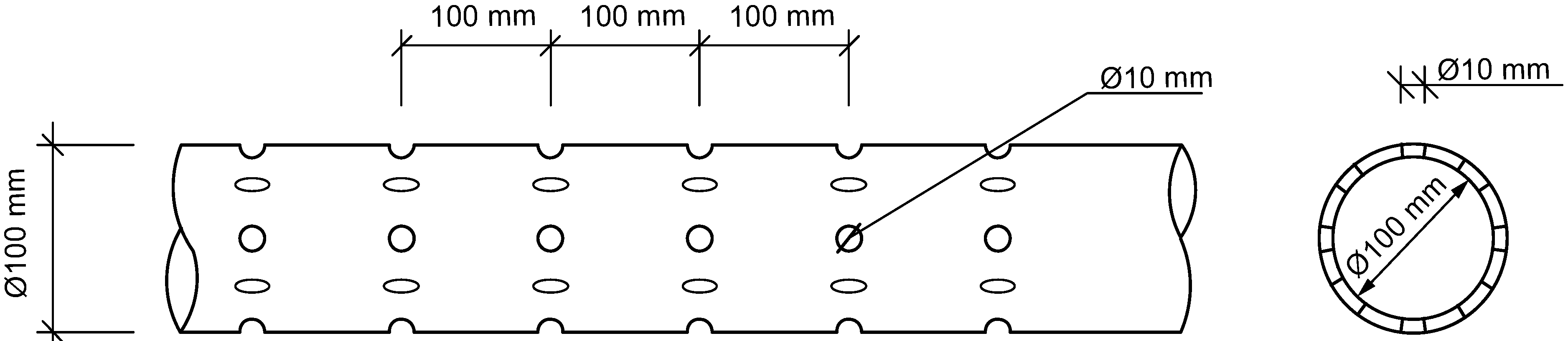
2.2. Slotted Drainage Pipes

The slotted drainage pipes, as shown in Figure 3a, use a polyethylene (PE) material and are designed with a combination of holes and slots [29]. The outer diameter of the pipe and the wall thickness of the pipe are 75 mm and 6 mm, respectively. Figure 3b shows 12 permeable slots that are evenly distributed along the longitudinal wall of the pipe. Holes with 8-mm diameter are designed in a spiral shape with a spacing of 150–200 mm on the bottom of the seepage slots. Braided screens of stainless steel wire are used in the filter layer of the drainage system. According to the principle of drainage and depressurization of the filter layer, the pore diameter of the stainless steel wire is matched with the composition of the tailing particles, as shown in Table 1.
With this arrangement, seepage that previously went through the holes is replaced by seepage through the slotted surfaces, which is beneficial for increasing the seepage area of the drainage pipe in the tailings dam. Through rough calculations, the use of the proposed new drainage structure can increase the seepage capability to approximately 20 times more than that of the traditional drainage structure.
Traditional drainage pipes (Figure 4) are widely used in practice in China. The diameter of a traditional drainage pipe is 100 mm, and 8 holes with diameters of 10 mm are located in a section of the pipe. The seepage area of a single hole is equal to 3.14 × (5 mm) = 78.5 mm2. The values of the contact area (CA) and the total seepage area (SA) of a 1 m pipe are equal to 3140 cm2 and 61.80 cm2, respectively. Therefore, the seepage ratio (SR) is (62.80/3140) × 100% = 2%. However, for the slotted drainage pipe, the SA value of a permeable slot is equal to 1000 mm × 10 mm = 100 cm2. There are 12 permeable slots distributed along the longitudinal wall of a pipe, and the total SA value is 1200 cm2. Therefore, the SR value is 38.2%. By comparing the values of the SRs, it is clear that the new drainage pipe can raise the seepage capability by approximately a factor of 20.

2.3. Drainage Pipe Filter

The choice of the filter layer directly determines whether the drainage system can be maintained. The improved new drainage pipe is clad with stainless steel wire braided screens, as shown in Figure 3c. The new filtering net mesh is selected after the size distribution of the tailings sands is investigated and analyzed, and this mesh prevents tailings of certain sizes from entering the permeable slots. To improve the filter permeability performance and enlarge the permeable area, this design allows approximately 80% of the fine tailings to pass through the wire screen, while 20% of the coarse sands stay outside of the screen. Therefore, the possibility of blocking and the failure of the proposed drainage pipes is lower than in traditional drainage pipes. For calculating the thickness of the filter layer, which can be used to determine the median element of the substructure technique during simulations, it can be assumed that the filter layer is a regular circle. Based on the law of mass conservation and Darcy’s law, the seepage of the equivalent filter layer is equal to the seepage of the drainage pipe, which can be written as follows:
1 / 4 π D 2 v 1 = 1 / 4 π d 2 v 2
where D and d are the diameters of the equivalent filter layer and the drainage pipe, respectively, and v1 and v2 denote the discharge velocity of the tailings and filter layer, respectively.
v = k i
Here, k is the permeability coefficient, and i is the hydraulic gradient.
When neglecting the loss of the water head, i1 = i2, the permeable coefficient k = Cd2, (Liu et al. 2005).
Substituting Equation (2) into Equation (1) provides
D 2 d 20 2 = D 20 2 d 2
and
D = ( D 20 / d 20 ) d
where d20 and D20 are the equivalent diameters of the tailings and the filter layer, respectively; D20 can be obtained by redrawing the gradation curve in which the particles smaller than a certain size are removed.
The slotted pipe has the effect of an anchor pulling and reinforcing the tailings dam. The stability of the tailings dam is increased to some extent. Therefore, the requirements for a long-term and effective drainage system of the tailings dam can be satisfied.

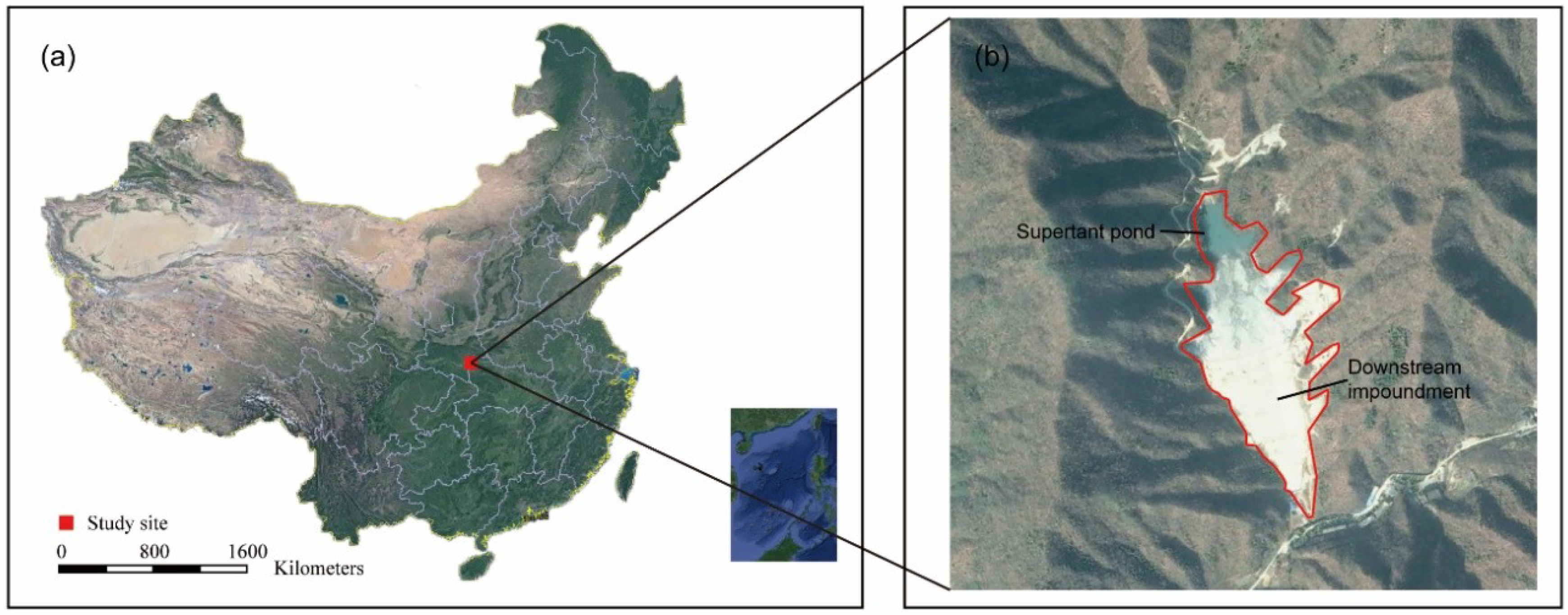
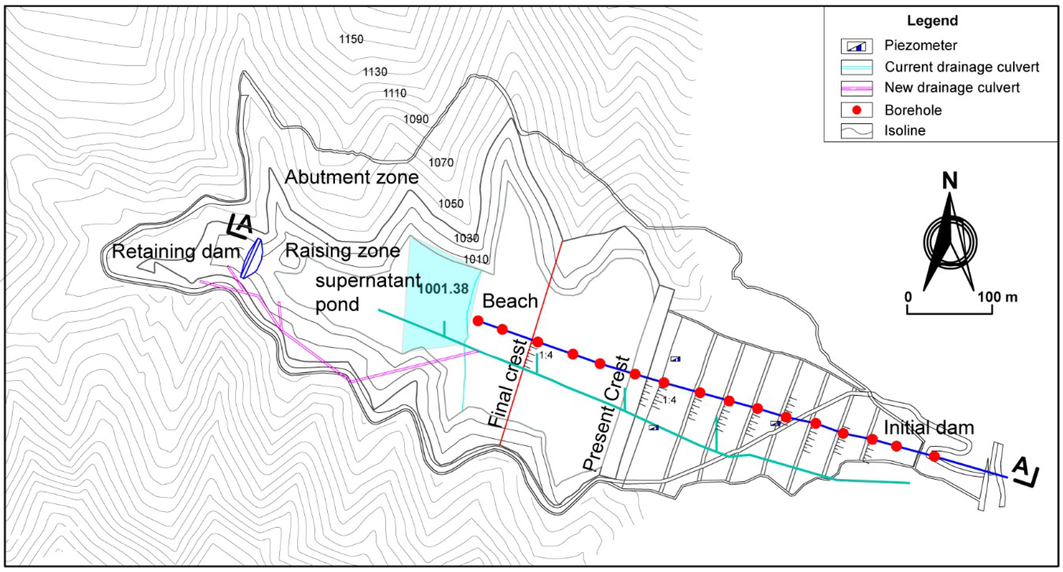
3. Site Characterization of the Xigou Tailings Dam

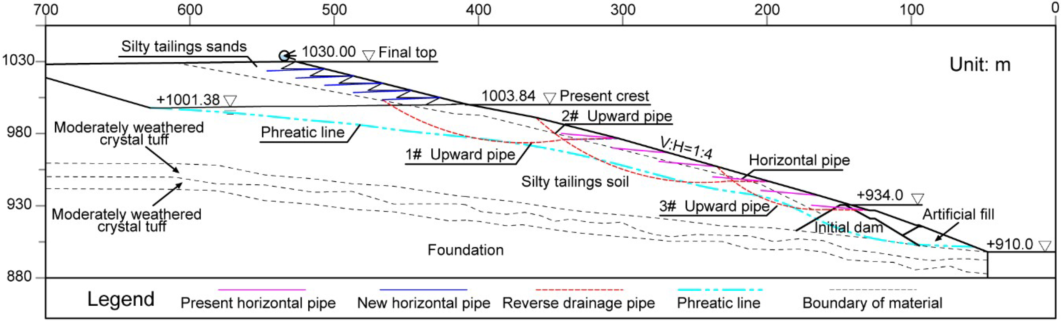
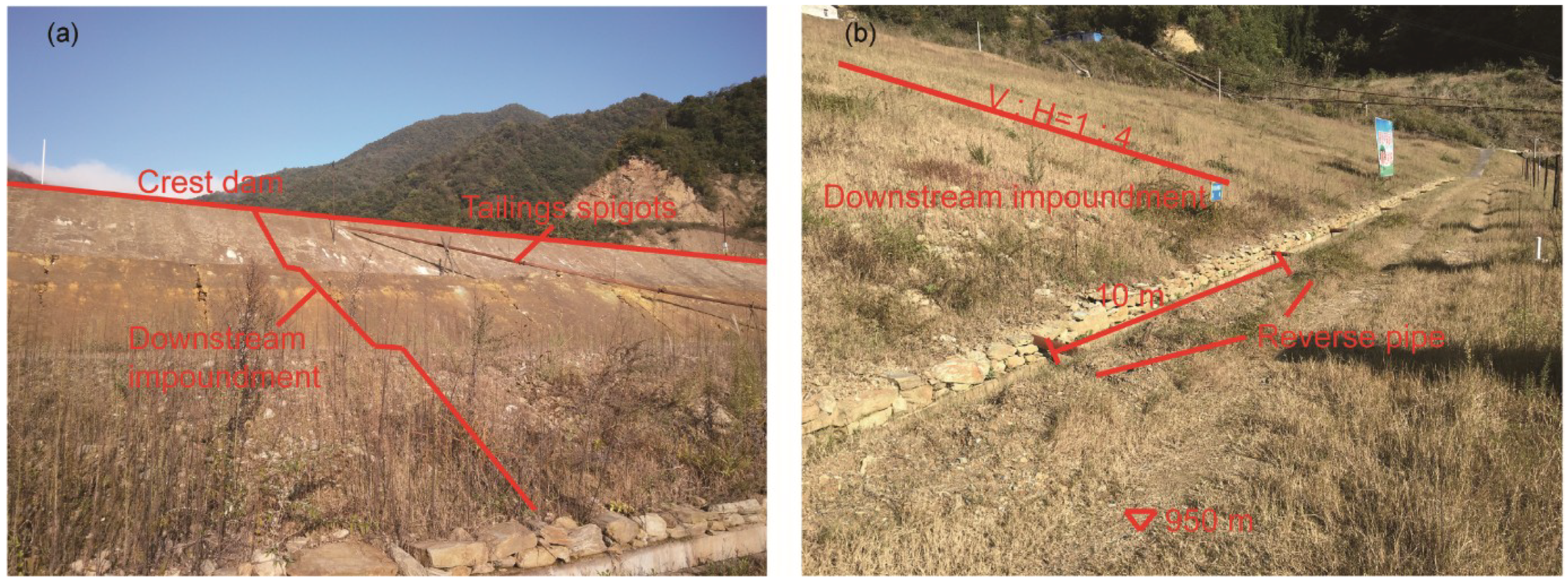
3.1. Project Description

The Xigou silver mine is located in Shiyan City in the northeast area of the Hubei Province in China. As shown in Figure 5, the tailings dam was raised using the upstream method in a narrow V-shaped valley, in which the valley bank slopes are steep, with a gradient of approximately 40–60 degrees on the northern hill and a gradient of approximately 30–50 degrees on the southern hill. To take advantage of the natural closed basin, a cross-valley permanent tailings pond was constructed. The tailings slurry was discharged into the pond through multiple spigots in the pipeline along the dam embankment.
An initial dam was built using locally available, residual rockfill material. The height and crest width of this dike were 18 m and 5 m, respectively. The dam was designed to have an upstream slope of 1 V: 1.7 H (vertical: horizontal) and a downstream slope of 1 V: 2 H. With the addition of a tailings discharge, the crest of the dam was progressively raised over the past 20 years or more, and the tailings dam was completely filled in according to the terms of the original design. Currently, the most important challenge faced by the mining company is the disposal of forthcoming waste ore. To save land, reduce costs, and ensure the mining company’s safety and sustainable development, the company decided to expand and increase the height of the current tailings dam and improve the storage capacity of its waste ore.
Figure 6 presents a typical cross-section of the Xigou tailings dam. The different material zones are illustrated in the diagram. The base and abutments of the dam consist of strongly weathered and moderately weathered crystal tuff. The tailing material zones are composed of silty sand tailings and silty soil tailings. The rest of the material zones, categorized as man-made soil, are shown. The bottom of the tailings dam is at an elevation of 910 m, while the current dam crest elevation is at an elevation of 1003.84 m. The upstream slope ratio is 1:4 (V:H) (Figure 7). To meet the needs of mining production, the ultimate planned height of the tailings dam is 100 m, and the crest elevation will exceed an elevation of 1030 m. The ultimate storage capacity of the Xigou tailings dam is 253.45 million m3. According to the national design codes of China [30], after increasing the height, the tailings dam is classified as grade 3. However, considering that the poisonous tailings can pollute and pose a hazard to the community and ecosystems near the mining areas, the dam must be raised to grade 2 when checking the safety factors of the slope stability.

3.2. Layout of the Seepage Control System

According to the hydrogeologic conditions of the tailings dam with an increased height at the site, a seepage control system consisting of horizontal drainage pipes and upward bending slotted drainage pipes is proposed in the slope of the dam, as shown in Figure 6. The horizontal drainage pipes consist of the current pipe and the planned pipes. Based on the national design standard and experience in similar projects, the current horizontal drainage pipes were arranged at elevations of 934, 940, 950, 960, 970, and 985 m, and the planned straight pipes were designed at elevations of 1003, 1008, 1013, 1018, and 1023 m. The horizontal spacing of each row of drainage pipes for both the current and ultimate conditions is 10 m, and the length of each drainage pipe is 40 m. The inclined angle between the straight drainage pipe and the horizontal direction is 5 degrees. The tailings dam contains 3 layers of slotted drainage pipes that are constructed from the line segment and the upward bending section. The first layer of the upward bending pipe intersects with the horizontal drainage pipe at an elevation of 1002 m. The lengths of the horizontal section and the curve section are 40 m and 154 m, respectively. The highest point and the lowest point of the second layer of the upward bending pipe are arranged at elevations of 996 m and 950 m, respectively. The length of the line section is 30 m, and the total length is 136 m. The third layer of the upward bending pipe intersects the embankment at elevations of 934 m and 960 m, respectively. All the pipes are made of PE material and DN100 slotted pipes. The equivalent diameter of the filter layer is 0.75 m and it is determined by analyzing the size distribution of the tailings sands.

4. Seepage Control System in the Xigou Tailings Dam with an Increased Height

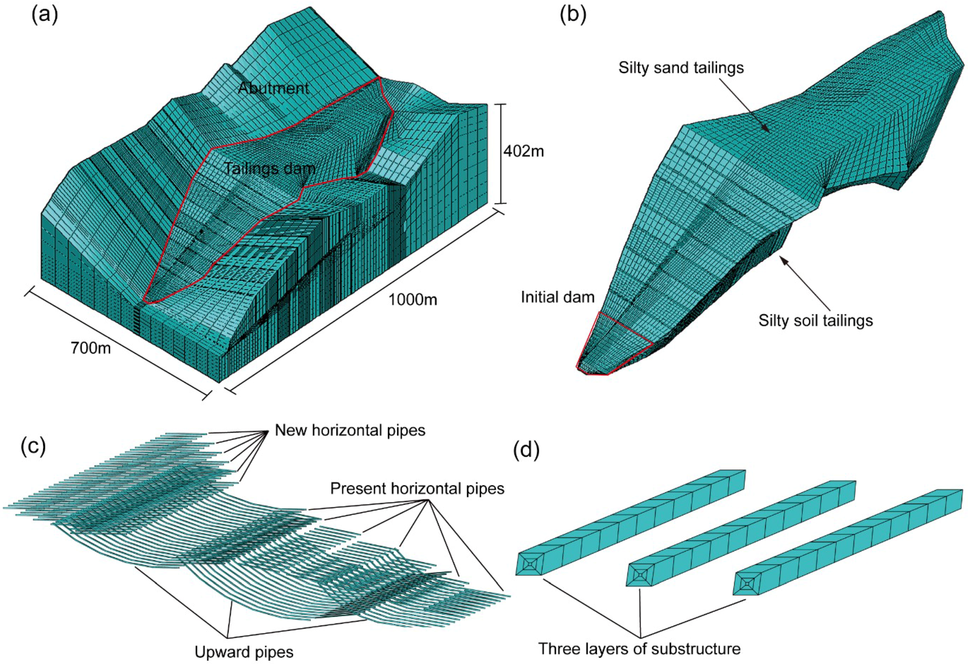
4.1. The Finite Element Model

Before the calculation is performed, the construction of a 3D finite element model can be performed as follows: specify the range of the numerical simulation, determine the type of elements and the type of analysis, locate the position of geometry, input the material parameters, input the boundary conditions, mesh generation, and set the initial conditions and calculation phases.
As shown in Figure 8a, a three-dimensional finite element mesh was generated for evaluating the performance of the seepage-proof system design and the impact of increasing the height at the Xigou tailings dam project. This model consisted of 356,221 nodes and 985,641 brick elements (with a small number degenerated into tetrahedral elements). The size of the numerical model was 700 m in the direction of the dam axis and 1000 m in the direction parallel to the river. The bottom of the model was at an elevation of 800 m, and the highest elevation of the model was 1202 m. The topographic and tailings material zone, as well as the seepage-proof system including the horizontal pipes and the bending slotted pipes, are shown in Figure 8b–d.
The boundary conditions were defined as follows: corresponding to the water level of a tailings pond, the hydraulic head on the upstream dam surface was variable at different raising stages, and the water head was constantly 910 m on the downstream dam surface. The lateral and bottom boundaries in the model were taken to be impermeable. The potential seepage boundaries were applied at the remaining boundaries, including the tailings dam surface and the ground above the upstream and downstream water levels, the embankment, and the boundaries of the drainage pipe. The potential seepage boundary satisfied Signorini’s complementary condition.

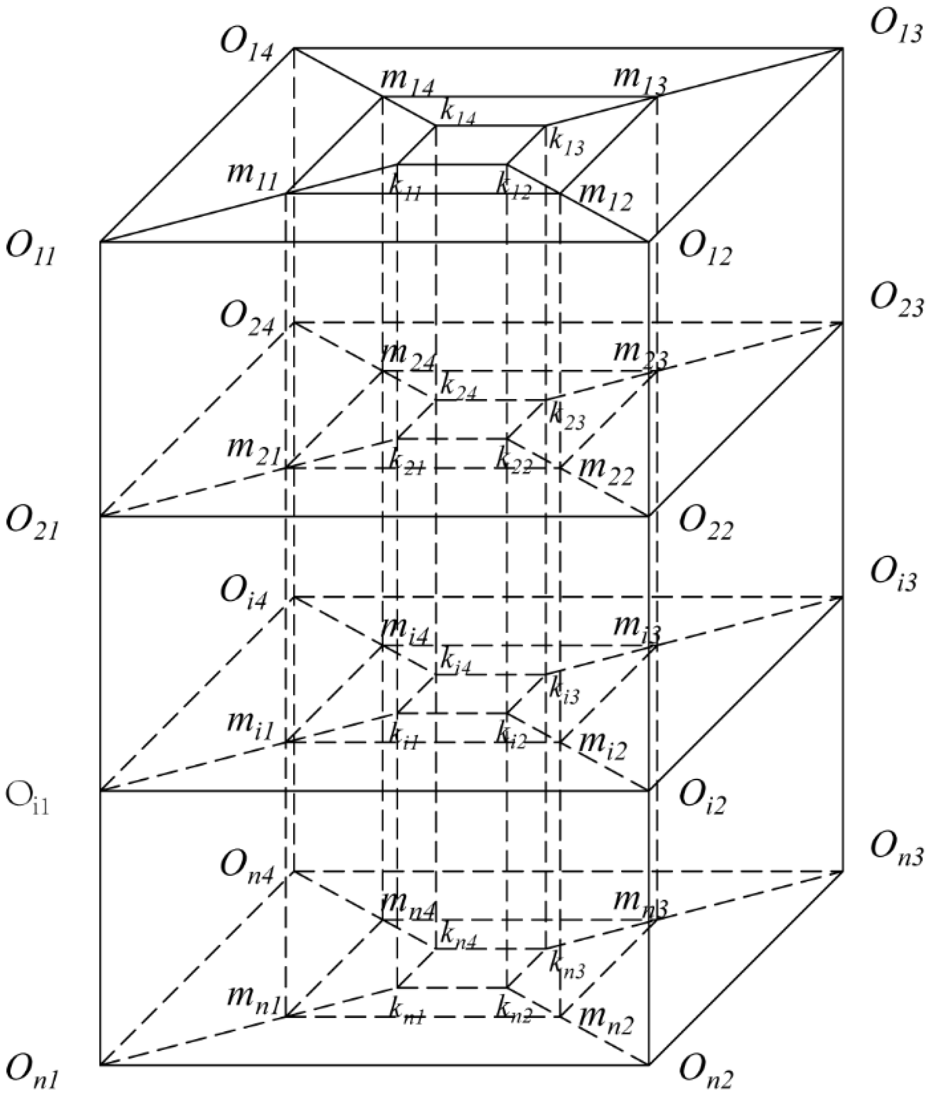
4.2. The Substructure Method and Boundary Conditions

Non-steady saturated seepage flow was used in this paper. The substructure method was proposed by modeling a densely deployed drainage pipe of a small diameter by subdividing the drainage element. Three-layer elements exist in each cross-section of the drainage pipe (Figure 9). From the boundaries of the drainage pipe to the element face in the radial direction, the original elements, the filter elements, and the drainage element are identified. The perimeter lengths of the filter and drainage elements are consistent with the circular cross-sections of the filter and pipe. The inner boundaries of the drainage element as the potential seepage surface are specified as the complementary condition of Signorini’s type [31]. This condition is represented as follows:
{ ϕ z ,   q n ( ϕ ) 0 ( ϕ z ) q n ( ϕ ) = 0   ( on   Γ s )
where Γs is the potential seepage boundary, ϕ is the total water head, qn is the flux out of the boundary, and z is the vertical coordinate.
Combined with the substructure technique and the variational inequality formulation of Signorini’s type, the singularity at the seepage points can be eliminated to reduce the work involved with generating the mesh and solving the equation.

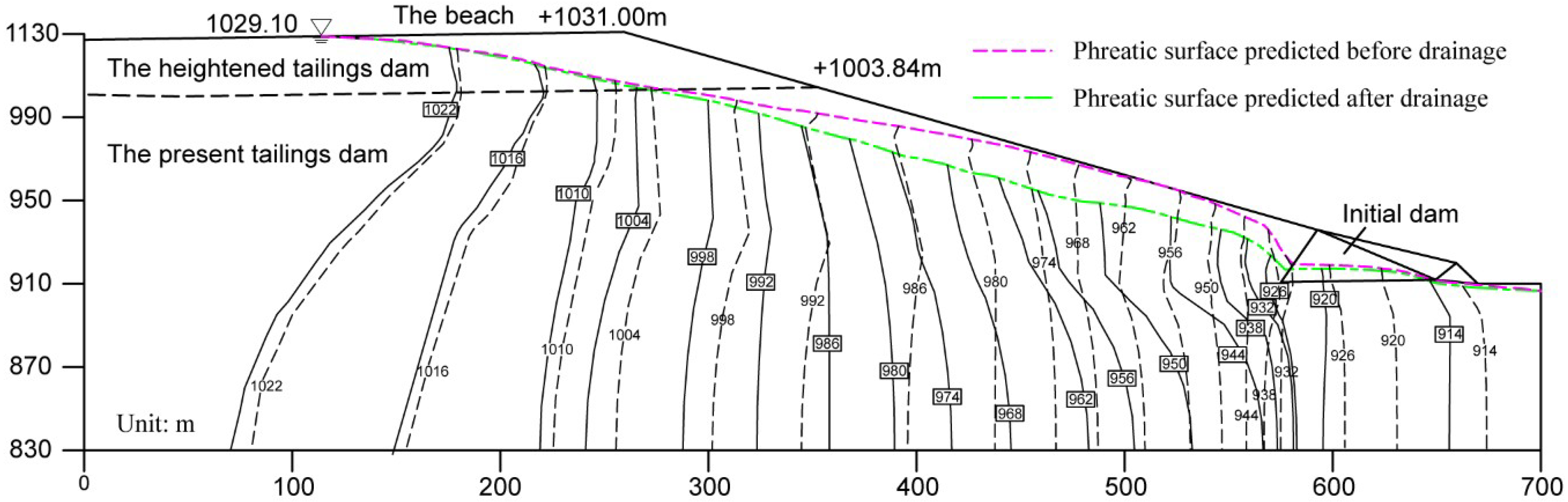
4.3. Phreatic Surface of the Tailings Dam

To obtain the initial hydraulic properties and the phreatic surface of the tailings dam, 16 boreholes were arranged at the dam site (with the locations of the boreholes as shown in Figure 6. According to the geological engineering survey results, the initial permeability coefficients of each material are shown in Table 2, as the permeability coefficients of the tailings materials and foundation are different from depths to depths and from locations to locations [32]. A limitation of the borehole tests is that only part of the region’s permeability coefficients is estimated [33]. The borehole testing results could not be used to calculate a numerical model. To obtain the precise permeability coefficients used for calculations, the MPSO-BP method and the in-house made finite element code were used to back-calculate the initial seepage field [34].
Along the main channel, 16 piezometers were installed to continuously measure the phreatic surface and its range of variation. Using the observation wells in the boreholes, the steady-state groundwater level was measured during the exploration of the Xigou tailings dam. Figure 3 presents the location of the phreatic line at the typical cross-section. The groundwater level reflected the normal conditions of the tailings dam and was used as the initial seepage field because the seepage control system was designed according to this condition. The distribution of the water head of the initial seepage field could be used for back analysis. The basic idea of the MPSO-BP method is that the difference between the measured water heads at the boreholes and the fitness water heads is minimized. The objective function can be written as
min f = i = 1 n w i ( h i c h i m ) 2
where n is the total number of piezometers, wi is the weight at the ith borehole, and h i c and h i m are the calculated and measured water heads at the ith borehole, respectively.
The iterative process of the back-calculation was implemented with the MPSO-BP method based on a modified particle swarm optimization algorithm and a neural network simulator. The algorithm parameters were as follows: the maximum iterations is 1000, the number of particles is 20, weight function ω = 0.4–0.9, c1 = 3.3, and c2 = 1.7. The back-analysis results showed that when the permeability coefficients of all the materials at the site were taken in Table 2, the value of the objective function was minimized at all observation boreholes. Figure 10 compares the calculated and measured groundwater levels at each borehole, indicating that the initial seepage field was reasonably simulated using the back-calculated permeability coefficients. The range of error could be controlled to below 5% between the calculated and measured phreatic surface, which also verified the rationality of the inverse results. Therefore, the back-calculated permeability coefficients were acceptable for a further performance assessment of the seepage.

4.4. Numerical Results

4.4.1. Performance Estimation of the Seepage-Proof System

In this section, the performance assessment of the proposed seepage control system after the height of the dam was increased was described under extreme operating conditions using the previously proposed method. Under this condition, the water level of the tailings impoundment was 1029.0 m from the flood prevention calculation. With the calculation of the finite element model, the distribution of the water head and the free surface of the typical cross-section were compared under the two conditions of setting drainage and without drainage, as shown in Figure 11. Initially, no additional seepage control structure was set up during operation. The distribution of the water head changed along the axis of the dam, and the equipotential line was relatively sparse upstream of the dam, while the equipotential line was highly dense near the junction of the heaping dam and the initial dam. The phreatic surface was smooth in the upstream tailing zone, but it was out of the dam slope downstream. When it reached the initial dam, the phreatic line showed a significant depression due to the high-permeability rockfill material, which then traveled downstream in a nearly horizontal state. The predicted maximum seepage gradient was 1.50, which appeared at the junction of the heaping dam and initial dam.
To decrease the phreatic surface, the new seepage control system was arranged in the process of increasing the dam height. The predicted seepage field of the finite element simulation is illustrated. Figure 11 plots the phreatic line and pressure head distribution of the whole seepage field (with the real line representation). Clearly, the phreatic line was reduced, the variation in the water head was gentle, and the free surface no longer escaped from the downstream slope. By calculating the seepage gradient, the maximum seepage gradient decreased from 1.50 to 0.83, which occurred at the same location as in the system without drainage. Figure 12 presents the three-dimensional free surface and the contour map of the groundwater level distribution and shows that due to the sufficient seepage-proof system, the distribution of the seepage flow field was more uniform in the tailings area, and the overall fluidization was smoother compared with the absence of the drainage system. The above numerical results clearly indicate that the proposed new seepage control system can not only effectively reduce the seepage pressure and depress the pore water stresses but also improve the overall groundwater movement trend and the local seepage field. These effects should be properly considered in the performance assessment of the seepage-proof system.

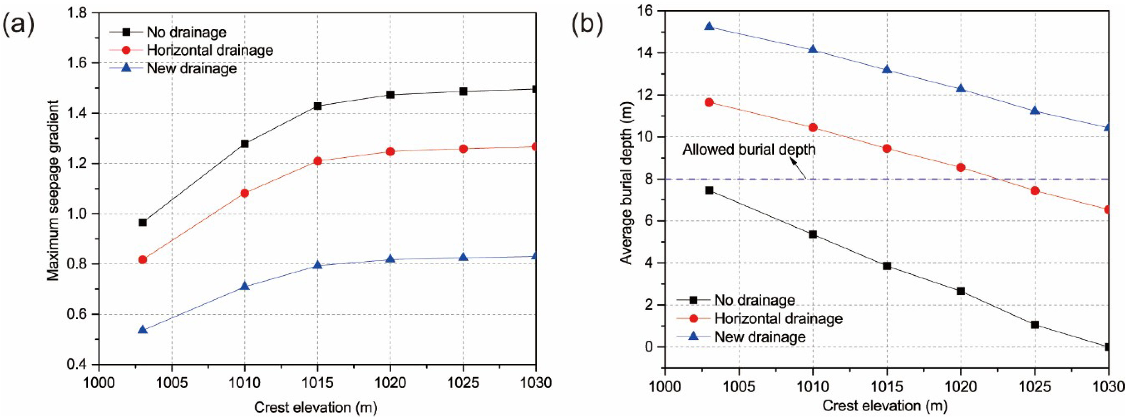
4.4.2. Comparison of the Seepage Results with Different Drainage Conditions

To further evaluate the effectiveness of the new drainage system, the performance assessments of the seepage without drainage measures, with only horizontal drainage measures and with the proposed drainage measures were compared and analyzed. The process of increasing the height of the dam was divided into five stages to simulate the sequential raising of the dam. In each filling stage, the influence of the seepage control system and the variation in the seepage gradient were researched under the three different drainage conditions. Figure 13 shows the change in the maximum seepage gradient values and the minimum depth of the phreatic surface when the tailings dam was raised sequentially, indicating that if there was no drainage system, then the behavior of the phreatic surface was inconsistent and changed sharply in the location position, leading to a large seepage gradient and a shallow burial depth. After the horizontal drainage pipe was arranged in the heightened slope, the overall and local seepage gradient was improved, causing the maximum seepage gradient to be reduced by approximately 15% and the minimum burial depth to be increased by approximately 5.6 m; however, the minimum burial depth was slightly higher than the national standard during the last two stages. Due to the effect of the water guide of the upward bending slotted pipe, the proposed drainage system acted as a drainage channel, which could accelerate the dissipation of pore water stresses and the process of consolidating the tailings slurry to further reduce the free surface. A stable seepage field could be observed during various raisings. The maximum seepage gradient was reduced by approximately 40%, and the minimum burial depth was increased by approximately 9.3 m. Compared with only horizontal drainage pipes, all the minimum burial depths with new drainage pipes met the national standard. All three of these cases reflected the characteristics of the increase in the seepage gradient and the decrease in the depth with the rise of the tailings pond. However, the performance of the new seepage control system was better than the other two cases.

4.4.3. Local Failure Analysis of the Drainage Pipe

During the construction and long-term operation of the tailings dam, the drainage pipes may be blocked, which results in a local blockage and low permeability of some drainage pipes in the seepage system [35,36]. Therefore, to further confirm the rationality of the new drainage system, a stochastic simulation analysis was carried out for a new drainage system due to partial blockage resulting in a decrease in the permeability coefficients. It was assumed that the blockage probability of all drainage pipes was random and had a uniform distribution. The simulation method and steps of the local failure of the drain pipe are as follows.
  • Select the object elements, including the horizontal and upward bending drainage pipes for the three-dimensional finite element model, and then set the percentage of the local failure.
  • Introduce the concept of random numbers, and sample them randomly according to the uniform distribution. When the ratio, which denotes the sum of the volume of the damaged elements to the total volume of drainage elements, reaches the set percentage of local failure, the sampling is stopped.
  • Modify the permeability coefficients of the random sampling elements to be consistent with the nearby tailings material.
A total of 20 groups of samples were generated for the 5% random local blockage rate of the drainage pipes, and the seepage calculation was carried out. Two positions in the tailings dam were selected to record the elevation of the phreatic line, and a statistical analysis was conducted. As shown in Figure 14, when the number of samples reached 13 groups, the average elevation of the phreatic line at two positions tended to be stable. Therefore, it could be considered that the selected random sample number was representative. The average value of the phreatic surface of the tailings dam could converge under the condition of a random local blockage. The 20 groups of samples were calculated and analyzed, and the upper and lower envelope graphs of the phreatic line of the tailings dam were drawn, as shown in Figure 15a. Compared with the seepage field without blockage, a 5% random local failure had some influence on the phreatic line of the tailings dam. The local phreatic line had a larger deviation than that without the blockage, and the maximum height difference between the upper and lower envelopes reached 6.5 m, occurring near the initial dam. The maximum seepage gradient reached 1.33, but it did not exceed the dam body’s allowable seepage gradient.
Similarly, 20 sets of samples were generated for the calculation and analysis of the 10% random local failure. The numerical results are shown in Figure 15b. The variation rule of the seepage field was consistent with the 5% blockage condition, except that the degree of deviation of the local free surface was increased, and the maximum height difference between the upper and lower envelopes reached 9.6 m. The maximum seepage gradient of the dam increased by 0.14 of that of the 5% failure and was still within the permissive seepage gradient.

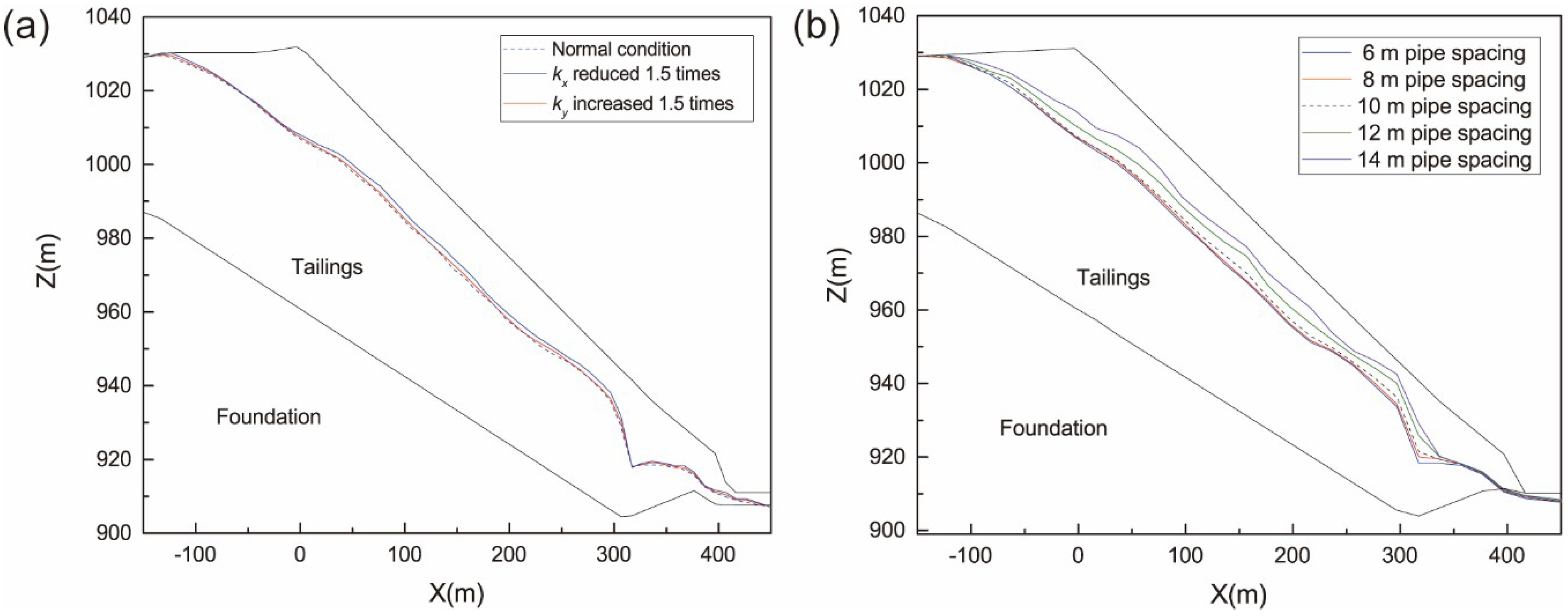
4.4.4. Sensitivity Analysis of the Tailings Material

Considering the randomness of the tailings drainage process and the uncertainty of sedimentation, a sensitivity analysis of the permeability coefficients of the tailings to the seepage field during the construction and operation of the tailings dam was carried out. To further understand the drainage effect of the new drainage system, the horizontal permeability coefficient of the tailings was reduced by 1.5 times, or the vertical permeability coefficient was increased by 1.5 times. Reducing the horizontal or increasing the vertical permeability coefficient was equivalent to exerting a water-blocking effect on the dam. This meant that the phreatic surface of the dam would be uplifted. To prevent seepage damage, the drainage system must have a stronger ability to guide water.
The simulation results from Figure 16a show that after the horizontal permeability coefficient was decreased by 1.5 times, the free surface of the tailings dam was raised, with an average uplift of 4.5 m and a maximum uplift of 6.3 m. When the vertical permeability coefficient was increased by 1.5 times, the elevation of the phreatic surface of the dam was not obvious and was only noticeable in the locally uplifted area, with an average uplift of 2.9 m and a maximum uplift of 3.6 m. The calculation indicates that the performance of the seepage-proof system is less sensitive to the variation in the permeability coefficient of the tailings materials.

4.4.5. Sensitivity Analysis of the Drainage Pipe Spacing

The seepage flow behaviors in the tailings dam with an increased height are usually related to the spacing of the drainage pipes. If the drainage pipes are more densely installed, the elevation of the phreatic surface can be more drastically lowered. However, with a decrease in the pipe spacing, the construction becomes more difficult, and the construction costs increase. To design a reasonable drainage pipe spacing, a spacing from 6 m to 14 m with an increment of 2 m was simulated to assess the performance of the seepage behavior. Currently, the drainage pipe spacing was taken to be 10 m according to the design requirements.
The numerical results with different pipe spacings are depicted in Figure 16b, indicating that with a decrease in the pipe spacing, the phreatic surface was significantly reduced in the tailings dam, especially when the pipe spacing was larger than 10 m. The change in the pipe spacing in a certain range had no significant effect on the phreatic surface. When the pipe spacing decreased from 10 m to 6 m, the location of the phreatic surface showed marginal sensitivity and increased by only 1.7 m for a 6 m pipe spacing and by 2.5 m for an 8 m pipe spacing compared to a 10 m pipe spacing. However, when the pipe spacing was increased from 10 m to 14 m, the increase in the free surface was rapid, and the phreatic surface increased by 7.2 m and 10.6 m for the 12 m pipe spacing and 14 m pipe spacing, respectively. Therefore, the designed 10 m pipe spacing was suitable for the drainage pipe arrangement.

5. Stability Analysis

The stability of a slope depends on its geometry, its material properties, and the position of the phreatic surface [37]. The geometry and the material properties of the Xigou tailings dam were obtained according to the results of the geotechnical investigations and laboratory experiments, as listed in Table 3. The previously calculated effect of the three-dimensional FEM was used to locate the phreatic surface [38]. For simplicity, the stability of the tailings dam can be viewed as a two-dimensional plane-strain problem, and the stability analysis can be performed using the Slope/w software packages in the basis of saturated soil mechanism [39]. According to the Chinese national codes, ordinary rigid LEMs, including the Swedish method of slices and a simplified Bishop method, are recommended to obtain a factor of safety (FOS) and analyze the stability of tailings dams under different conditions.
(a) For the Swedish method of slices, the FOS is written as
F s = Σ [ c j b j sec α j + ( W j cos α j u j b j sec α j ) tan ϕ j ] Σ W j sin α j
(b) For the simplified Bishop’s method of slices, the FOS is written as
F s = Σ [ c j b j + ( W j u j b j ) tan ϕ ] 1 m j Σ W j sin α j + Σ Q j e j / R
m j = cos α j + tan ϕ j sin α j F s
where bj is the width of the jth slice; αj is the angle of the jth slice bottom with the horizontal slice; Wj is the weight of the slice; c’ and ϕ’ are the effective cohesion and the effective angle of friction that develop along the potential failure surface, respectively; and uj is the average pore water pressure at the bottom of the jth slice; Qj is the horizontal inertial force; R is radius of circular failure surface; and ej is vertical height between Qj and the center of the failure circle.
To estimate the stability of the tailings dam, the FOSs of the heightened tailings dam were calculated under various conditions, such as a normal water level, an extremely high water, and special operations. The seepage-proof system played a significant role in the stability. For comparison, the cases of no drainage and horizontal drainage were estimated. At the same time, considering the randomness of the tailings drainage process and the uncertainty of sedimentation, the FOSs under the condition of a change in the permeability coefficient were calculated. Under the seismic working condition, the FOSs were obtained using a quasi-static method according to the National Code of China [31]. An earthquake ground acceleration of 0.15 g was used based on the location of the mine, which was classified as being in earthquake zone VII.
The calculation results, presented in Figure 17 and Table 4, show that when the new drainage system is implemented properly, the tailings dam is safe under a variety of working conditions, and the safety factors, including the Swedish method of slices and the simplified Bishop’s method, meet the requirements. When there was no drainage system, the slope was unstable under different working conditions. If only the horizontal drainage system was used, the FOSs met the national standard under the normal water level, while the FOSs were marginally lower than the value required by the national code under the extremely high level; for the seismic working condition, the FOSs of the Swedish method of slices and the simplified Bishop’s method were 1.106 and 1.165, respectively, and marginally satisfied the national code. Therefore, the design of the new drainage system effectively reduced the phreatic surface and enabled the higher tailings dam to meet the relevant national requirements for sliding stability.

6. Conclusions

To satisfy the needs of the mining industry for extending its tailings pond storage capacity, a new drainage method was suggested to effectively decrease the phreatic surface. The proposed drainage system was successfully implemented in designing a seepage-proof system for the higher Xigou tailings dam where the seepage damage may increase. In this study, the MPSO-BP method was used to back-analyze the real permeability coefficients at the site, and a systematic case study of the seepage field analysis was performed using the substructure technique and the variational inequality formulation of Signorini’s type in a three-dimensional finite element model. The major conclusions are summarized as follows:
  • Compared with only setting horizontal drainage pipes or with no drainage pipes, the performance of the new drainage system not only effectively reduced the seepage pressure and depressed the water table but also improved the overall groundwater movement trend and the local seepage field.
  • A stochastic simulation analysis was carried out for analyzing the local failure of the new drainage system, in which 5% and 10% of local blockages have a marginal influence on the seepage field, and the upper and lower envelopes show a lower deviation from the free surface without local failure. The maximum seepage gradients reached 1.43 for the 5% local failure case and 1.57 for the 10% local failure case, but these values were still within the permissive seepage gradient.
  • The sensitivity analysis of the tailings material showed that the performance of the seepage control system was insensitive to the change in the horizontal and vertical permeability coefficients. The sensitivity analysis of the drainage spacing indicated that the designed 10 m pipe spacing was suitable for the drainage pipe arrangement.
  • Utilizing the LEM, the potential failure surface was evaluated, and the corresponding FOSs were obtained at different water levels. Comparing the FOSs under various drainage system conditions, it was obvious that the cases without drainage and with horizontal drainage seemed to lead to an unstable tailings dam under the normal water level or the extremely high water level. However, when the new drainage system was implemented properly, the tailings dam was safe under a variety of working conditions.

Author Contributions

C.L. and L.X. designed the framework and wrote the manuscript. C.L. and K.Z. collected the data. C.L. and Z.S. mainly responsible for the simulation analysis. C.L. and L.G. verified the results of our wor. C.L. and T.J. discussed the results and contributed to the final manuscript.

Funding

This research was funded by the Project of the National Natural Science Foundation of China/Yalong River Joint Fund grant number U1765205, the Project of the National Natural Science Foundation of China grant number 51609073, a Project Funded by the Priority Academic Program Development of Jiangsu Higher Education Institutions grant number YS11001, and the CRSRI Open Research Program grant number CKWV2017515/KY.

Conflicts of Interest

The authors declare no conflict of interest.

References

  1. Kossoff, D.; Dubbin, W.E.; Alfredsson, M.; Edwards, S.J.; Macklin, M.G.; Hudson-Edwards, K.A. Mine tailings dams: characteristics, failure, environmental impacts, and remediation. Appl. Geochem. 2014, 51, 229–245. [Google Scholar] [CrossRef]
  2. Shamsai, A.; Pak, A.; Bateni, S.M.; Ayatollahi, S.A.H. Geotechnical characteristics of copper mine tailings: A case study. Geotech. Geol. Eng. 2007, 25, 591–602. [Google Scholar] [CrossRef]
  3. Martin, T.E.; McRoberts, E.C. Some considerations in the stability analysis of upstream tailings dams. In Proceedings of the Sixth International Conference on Tailings and Mine Waste, Rotterdam, Netherlands, 24–27 January 1999; Volume 99, pp. 287–302. Available online: http://w3.cenn.org/cenn_projects/BfW_mining/Training/Managing%20Effects%20of%20Major%20Mines/Reference%20Materials/Tailing/Martin2002b.pdf (accessed on 5 October 2018).
  4. Yin, G.Z.; Li, G.Z.; Wei, Z.A.; Wan, L.; Shui, G.H.; Jing, X.F. Stability analysis of a copper tailings dam via laboratory model tests: A Chinese case study. Miner. Eng. 2011, 24, 122–130. [Google Scholar] [CrossRef]
  5. Zandarin, M.T.; Decop, L.A.; Rodriguez, R.; Zabala, F. The role of capillary water in the stability of tailing dams. Eng. Geol. 2009, 105, 108–118. [Google Scholar] [CrossRef]
  6. Vick, S.D. Tailings dam failure at Omai in Guyana. Miner. Eng. 1996, 11, 34–37. [Google Scholar]
  7. WISE. Chronology of Major Tailings Dam Failures. Available online: http://www.wise-uranium.org/mdaf.html (accessed on 29 August 2018).
  8. Psarropoulos, P.N.; Tsompanakis, Y. Stability of tailings dams under static and seismic loading. Can. Geotech. J. 2008, 45, 663–675. [Google Scholar] [CrossRef]
  9. Jakka, R.S.; Ramana, G.V.; Datta, M. Seismic slope stability of embankments constructed with pond ash. Geotech. Geol. Eng. 2011, 29, 821–835. [Google Scholar] [CrossRef]
  10. Rico, M.; Benito, G.; Diez-Herrero, A. Floods from tailings dam failures. J. Hazard. Mater. 2008, 154, 79–87. [Google Scholar] [CrossRef] [PubMed] [Green Version]
  11. Rico, M.; Benito, G.; Salgueiro, A.R.; Diez-Herrero, A.; Pereira, H.G. Reported tailings dam failures. A review of the European incidents in the worldwide context. J. Hazard. Mater. 2008, 152, 846–852. [Google Scholar] [CrossRef] [PubMed]
  12. Kwak, M.; James, D.F.; Klein, K.A. Flow behaviour of tailings paste for surface disposal. Int. J. Miner. Process. 2005, 77, 139–153. [Google Scholar] [CrossRef]
  13. Kollikkathara, N.; Feng, H.; Stern, E. A purview of waste management evolution: special emphasis on USA. Waste Manag. 2009, 29, 974–985. [Google Scholar] [CrossRef] [PubMed]
  14. Reid, C.; Becaert, V.; Aubertin, M.; Rosenbaum, R.K.; Deschenes, L. Life cycle assessment of mine tailings management in Canada. J. Clean. Prod. 2009, 17, 471–479. [Google Scholar] [CrossRef]
  15. Wei, Z.A.; Yin, G.Z.; Wan, L.; Li, G.Z. A case study on a geotechnical investigation of drainage methods for heightening a tailings dam. Environ. Earth Sci. 2016, 75, 106. [Google Scholar] [CrossRef]
  16. Xu, B.T.; Wang, Y.Y. Stability analysis of the Lingshan gold mine tailings dam under conditions of a raised dam height. Bull. Eng. Geol. Environ. 2015, 74, 151–161. [Google Scholar] [CrossRef]
  17. Wang, T.; Zhou, Y.; Lv, Q.; Zhu, Y.L.; Jiang, C. A safety assessment of the new Xiangyun phosphogypsum tailings pond. Miner. Eng. 2011, 24, 1084–1090. [Google Scholar] [CrossRef]
  18. Dixon-Hardy, D.W.; Engels, J.M. Guidelines and recommendations for the safe operation of tailings management facilities. Environ. Eng. Sci. 2007, 24, 625–637. [Google Scholar] [CrossRef]
  19. Zhang, D.M.; Li, S.; Wang, X.M.; He, Y. Super large-scale filtered tailing disposal on coal-mining subsidence land. Pol. J. Environ. Stud. 2017, 26, 1855–1863. [Google Scholar] [CrossRef]
  20. Fu, W.T.; Li, H.J.; Bo, F.Z. Discussion on the burial of drainage tube in tailings dam. Met. Mine 2010, S, 44–46. [Google Scholar]
  21. Jin, S.L.; Xu, H.D.; Zhang, W.; Yan, H. Research situation of drainage technology of tailings dam. Mod. Minging 2012, 28, 35–38. [Google Scholar]
  22. Li, X.; Chen, Y.F.; Hu, R.; Yang, Z.B. Towards an optimization design of seepage control: A case study in dam engineering. Sci. China-Technol. Sci. 2017, 60, 1–14. [Google Scholar] [CrossRef]
  23. Li, Y.; Chen, Y.F.; Jiang, Q.H.; Hu, R.; Zhou, C.B. Performance assessment and optimization of seepage control system: A numerical case study for Kala underground powerhouse. Comput. Geotech. 2014, 55, 306–315. [Google Scholar] [CrossRef]
  24. Wang, L. Analysis of seepage field near a drainage-holes curtain. J. Hydraul. Eng. 1992, 9, 15–20. [Google Scholar]
  25. Zhao, J.; Shen, Z.Z. Improvement of seepage calculation method for complex drainage system of tailings dam. J. Hohai Univ. (Nat. Sci.) 1997, 25, 110–113. [Google Scholar]
  26. Chen, Y.F.; Zhou, C.B.; Zheng, H. A numerical solution to seepage problems with complex drainage systems. Comput. Geotech. 2008, 35, 383–393. [Google Scholar] [CrossRef]
  27. Zhu, Y. Solution to seepage field problem with the technique of improved drainage substructure. Chin. J. Geotech. Eng. 1997, 19, 69–76. [Google Scholar]
  28. Zheng, H.; Liu, D.F.; Lee, C.F.; Tham, L.G. A new formulation of Signorini’s type for seepage problems with free surfaces. Int. J. Numer. Methods Eng. 2005, 64, 1–16. [Google Scholar] [CrossRef]
  29. Fu, W.T. Slot drainage tube-a new type drainage tube for tailings dam. Met. Mine 2009, S, 73–74. [Google Scholar]
  30. Code for Design of Tailings Facilities; GB No. 50863-2013; MOHURD (Ministry of Housing and Urban-Rural Development of the People’s Republic of China): Beijing, China, 2013.
  31. Chen, Y.F.; Hu, R.; Zhou, C.B.; Li, D.Q.; Rong, G.; Jiang, Q.H. A new classification of seepage control mechanisms in geotechnical engineering. Chin. J. Rock Mech. Eng. 2010, 2, 209–222. [Google Scholar] [CrossRef]
  32. Xu, T.L.; Wang, Y.B.; Chen, K. Tailings saturation line prediction based on genetic algorithm and BP neural network. J. Intell. Fuzzy Syst. 2016, 30, 1947–1955. [Google Scholar]
  33. Zhou, C.B.; Liu, W.; Chen, Y.F.; Hu, R.; Wei, K. Inverse modeling of leakage through a rockfill dam foundation during its construction stage using transient flow model, neural network and genetic algorithm. Eng. Geol. 2015, 187, 183–195. [Google Scholar] [CrossRef]
  34. Gan, L.; Shen, X.Z.; Zhang, H.W. New deformation back analysis method for the creep model parameters using finite element nonlinear method. Cluster. Comput. 2017, 20, 3225–3236. [Google Scholar] [CrossRef]
  35. Reddi, L.N.; Ming, X.; Hajra, M.G.; Lee, I.M. Permeability reduction of soil filters due to physical clogging. J. Geotech. Geoenviron. Eng. 2000, 126, 236–246. [Google Scholar] [CrossRef]
  36. Reddi, L.N.; Xiao, M.; Hajra, M.G.; Lee, I.M. Physical clogging of soil filters under constant flow rate versus constant head. Can. Geotech. J. 2005, 42, 804–811. [Google Scholar] [CrossRef]
  37. Ozcan, N.T.; Ulusay, R.; Isik, N.S. A study on geotechnical characterization and stability of downstream slope of a tailings dam to improve its storage capacity (Turkey). Environ. Earth Sci. 2013, 69, 1871–1890. [Google Scholar] [CrossRef]
  38. Lane, P.A.; Griffiths, D.V. Assessment of stability of slopes under drawdown conditions. J. Geotech. Geoenviron. Eng. 2000, 126, 443–450. [Google Scholar] [CrossRef]
  39. Stress-Deformation Modeling with Slope/W 2017 Version: An Engineering Methodology; GEO-SLOPE International Ltd: Calgary, AB, Canada, 2017.
Figure 1. A satellite image of the Xigou tailings pond.
Applsci 08 01840 g001
Figure 2. The layout of the drainage pipes. (a) Traditional approach. (b) A new drainage method combining a horizontal pipe with an upward bending slotted pipe.
Applsci 08 01840 g002
Figure 3. The structure of a slotted drainage pipe. (a) Pipe structure. (b) Pipe section. (c) Pipes are clad with the screen as a filter layer.
Applsci 08 01840 g003
Figure 4. The structure of a traditional drainage pipe.
Applsci 08 01840 g004
Figure 5. The schematic map of the Xigou tailings pond.
Applsci 08 01840 g005
Figure 6. The geological cross-section and the layout of the drainage control system.
Applsci 08 01840 g006
Figure 7. The Xigou tailings dam in 2017. (a) Downstream area. (b) Drainage pipes at an elevation of 955 m.
Applsci 08 01840 g007
Figure 8. (a) A 3D finite element mesh for the Xigou tailings pond with an increased dam height. (b) Tailings material zone. (c) Drainage control system. (d) Mesh of drainage pipes.
Applsci 08 01840 g008
Figure 9. The construction of a drainage substructure.
Applsci 08 01840 g009
Figure 10. The comparison between the measured and calculated values of the water head at the boreholes.
Applsci 08 01840 g010
Figure 11. The comparison of the hydraulic head contours and phreatic surface at a typical cross-section in the system without drainage and with the proposed drainage system.
Applsci 08 01840 g011
Figure 12. The comparison of the 3D free surface and the contour map of the groundwater level distribution in the system without drainage (a) and with the proposed drainage system (b).
Applsci 08 01840 g012
Figure 13. The comparison of the burial depth of the phreatic surface (a) and the maximum seepage gradient (b) in various cases.
Applsci 08 01840 g013
Figure 14. The fluctuation of the mean height of the phreatic surface at x = 0 and x = 100 m.
Applsci 08 01840 g014
Figure 15. The phreatic surface envelope diagram of drainage elements at (a) 5% blockage (b) 10% blockage.
Applsci 08 01840 g015
Figure 16. The comparison of the phreatic surface at a typical cross-section (a) for the cases with a change in the permeability coefficient and with different pipe spacings (b).
Applsci 08 01840 g016
Figure 17. The stability analysis results for the tailings dam (cases ah).
Applsci 08 01840 g017
Table 1. The aperture of the stainless steel filter.
Tailings d0.075/%9590807050403020105
Filtering Net Mesh Numbers120120100100808060606060
Table 2. The comparison between the measured and calculated permeability coefficients.
ParametersPermeability Coefficient (cm/s)Corrected Permeability Coefficient (cm/s)
Horizontal kxVertical kyHorizontal kxVertical ky
Moderately weathered crystal tuff2.3 × 10−72.1 × 10−72.5 × 10−72.3 × 10⁻⁷
Strongly weathered crystal tuff5.7 × 10−54.8 × 10−55.7 × 10−54.8 × 10⁻⁵
Initial dam3.3 × 10−33.3 × 10−31.5 × 10−32.1 × 10⁻³
Silty sand tailings5.0 × 10−44.5 × 10−45.1 × 10−44.3 × 10⁻⁴
Silty soil tailings8.0 × 10−56.4 × 10−58.2 × 10−57.1 × 10⁻⁵
Silty clay1.4 × 10−51.2 × 10−53.2 × 10−52.5 × 10⁻⁵
Artificial clay I5.1 × 10−55.1 × 10−55.1 × 10−55.1 × 10⁻⁵
Artificial clay II3.3 × 10−33.1 × 10−35.0 × 10−24.3 × 10⁻³
Table 3. The tests results of the physical and mechanical properties of the tailings samples.
ParametersVolume-Weight (kN/m3)Soil Indicators in Nature
Unity Weight (γ)Saturated Unity Weight(γd)Cohesion (c’) (kPa)Friction Angle (ϕ’) (°)
Moderately weathered crystal tuff26.927.92000.0 38.0
Strongly weathered crystal tuff24.525.550.0 27.0
Starter dam21.021.918.0 24.0
Silty sand tailings19.220.14.0 30.0
Silty soil tailings19.920.98.0 27.0
Silty clay19.720.624.0 20.0
Artificial clay I21.020.818.0 24.0
Artificial clay II22.021.712.0 20.0
Table 4. The calculated results of the FOSs (factor of safety) of the slope stability under different working conditions.
ConditionCaseFactor of Safety
The Ordinary Method of SlicesBishop’s Simplified Method
CalculatedStandardCalculatedStandard
Normal water levelNo drainagea1.2351.251.2681.35
Horizontal drainageb1.3211.251.3621.35
New drainagec1.5421.251.6771.35
Extremely high waterNo drainaged1.0631.151.1261.25
Horizontal drainagee1.1421.151.2361.25
New drainagef1.5211.151.5801.25
kx reduced 1.5 timesg1.4371.151.4781.25
ky increased 1.5 timesh1.4151.151.4561.25
Earthquakei1.1061.051.1651.15

