Article

Intra-Oral 3D Scanning for the Digital Evaluation of Dental Arch Parameters

by
Magdaléna Kašparová
1,
Simona Halamová
1,
Taťjana Dostálová
1 and
Aleš Procházka
2,3,*
1
Department of Stomatology, 2nd Medical Faculty, Charles University, 150 06 Prague, Czech Republic
2
Department of Computing and Control Engineering, University of Chemistry and Technology in Prague, 166 28 Prague, Czech Republic
3
Czech Institute of Informatics, Robotics and Cybernetics, Czech Technical University in Prague, 166 36 Prague, Czech Republic
*
Author to whom correspondence should be addressed.
Appl. Sci. 2018, 8(10), 1838; https://doi.org/10.3390/app8101838
Submission received: 27 August 2018 / Revised: 27 September 2018 / Accepted: 28 September 2018 / Published: 7 October 2018

Abstract

:
Intra-oral scanning technology has brought a completely new approach to examination methods in dentistry. In comparison to traditional plaster casts, it allows more precise digital analysis of dental arch components during the treatment of dental disorders. Data acquired can also be used for the creation of three-dimensional (3D) models using 3D printers. This paper describes a data acquisition system, the mathematical processing of resulting three-dimensional model, and the statistical analysis of selected parameters of the dental arch. The study aims at comparing the results achieved from 20 models of the same individual acquired by different specialists. The proposed methodology includes mathematical rotation of objects into the optimal plane defined by the teeth tops’ location to increase the accuracy of the resulting parameters. The mean evaluated distances between canines (3-3) and premolars (5-5) are 24.29 mm and 37.98 mm, respectively, for the lower dental arch. The proposed object rotation increased these distance by 0.9% and 1.4%, respectively, reducing the rotation error. Moreover, the variability of results decreased and the mean value of the coefficient of variation was lowered by 12%. Image registration was then used to evaluate changes of dental arch parameters. This paper presents the advantages of digital models for visualisation of the dental arch allowing its flexible rotation and evaluation of its parameters.

1. Introduction

Dental arch analysis forms an essential tool in examination of stomatological disorders and their treatment. Plaster casts have been used for many years and are now often replaced by digital models [1,2] that are constructed from magnetic resonance (MRI) records and intra-oral scanners [3,4,5,6,7]. Digital models introduced in late 1990s overcome several limitations of traditional plaster models that can be easily damaged, require time for model fabrication, and space for their storage [8].
The use of different sensors is essential for acquisition of digital models to estimate dental arch parameters or to print separate three-dimensional (3D) objects using 3D printers [9]. This modern interdisciplinary approach assumes a combination of knowledge from dentistry [10], optics [11], engineering [12], biomechanics [13], information technologies [14,15], and material sciences. Using digital technologies, orthodontists can more accurately analyze dental problems, their treatment, more precisely specify the refabrication tasks, and collaborate with further specialists as well.
Main types of dental scanners are based upon the mechanical principle with a touch-probe or more preferred contactless light scanners [8]. Figure 1 presents an example of such intra-oral scanner [11,16,17,18] that we used for data acquisition and for construction of a 3D digital model of the lower and upper dental arches. Each scanning device includes a handheld camera that is used to collect surface data inside the mouth region and a computer system to process, analyze and visualise the resulting 3D model. Either laser or white light is used for illumination of scanned area and its reflection is acquired by the sensor in the wand.
Scanning technologies [19,20] affect the measurement speed and accuracy [21]. The most common include [19] triangulation using laser light [22], parallel confocal imaging [23], or fringe interferometry [24] based upon projection of light patterns.
Data acquired are processed by different imaging technologies [5,19] and mathematical methods for object surface construction. The following analysis of digital dental models assumes the application of image processing methods, geometrical modelling [25], data denoising methods [26,27], morphological operations, image registration and statistical evaluation of results. The analysis of different intra-oral scanners [2,28] together with the application of mathematical methods for data processing, their visualization and evaluation contribute to their efficient use in stomatology [17].
In the context of medical imaging, image registration allows comparison and analyses of images taken at different times (multitemporal analysis), from different viewpoints, with different image acquisition devices (multimodal analysis; e.g., MRI and CT) or with different patient positions. In medicine, registration is required to monitor tissue evolution in time, for treatment verification, in surgery, and so on. These methods are also very important in dentistry to compare images of dental arches taken at different times.
The present paper is devoted to data acquisition recorded by an intra-oral scanner working on a contactless measurement basis and presented in Figure 1. A set of 20 records from one patient formed the database for the evaluation of dental arch parameters and for the estimation of their accuracy. To increase the reliability of the measurement, electronic dental arch models were rotated into the specific dental planes defined by the tops of individual teeth. This approach allowed a more precise comparison of dental arch changes [14] for separate scans.

2. Methods

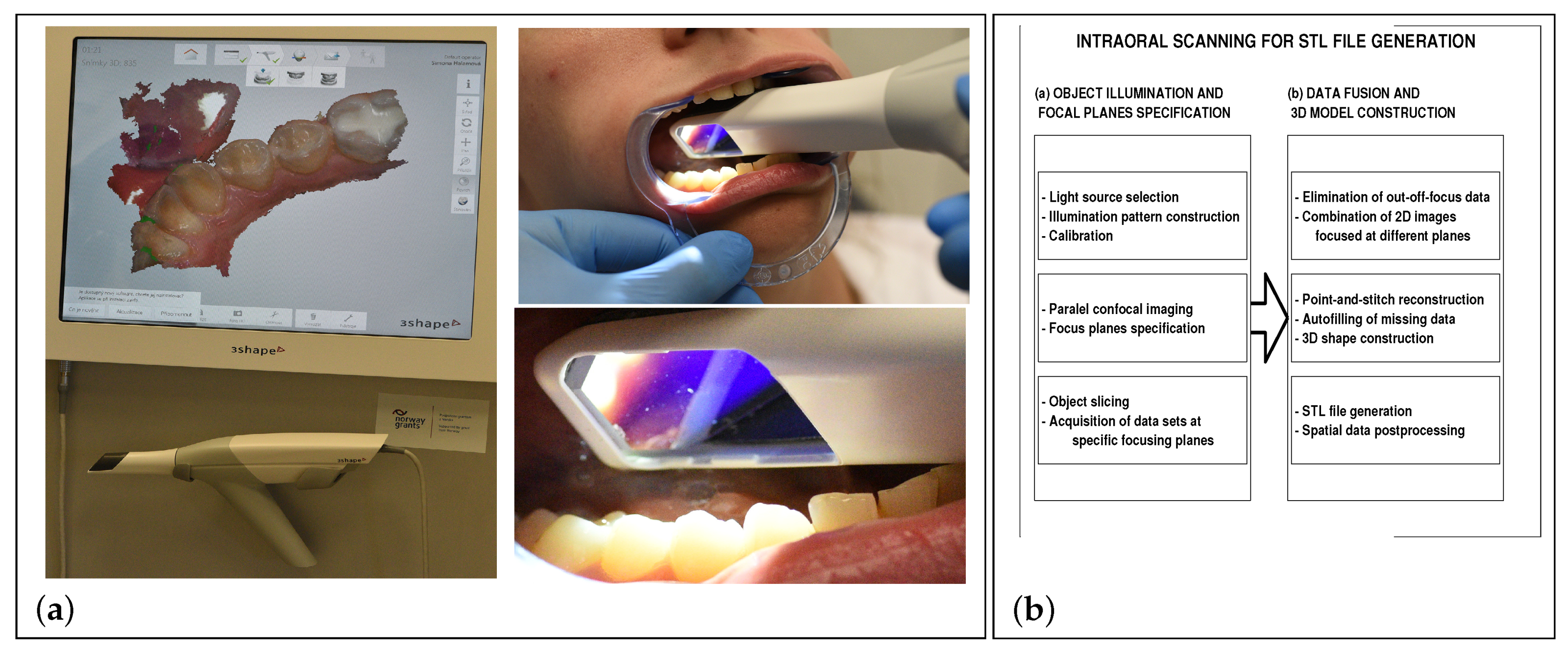
2.1. Data Acquisition

The digital dental model construction, processing and analysis are based upon data acquired by the widely used Trios system. This intra-oral scanning device, introduced by the 3shape company in 2010, uses advanced parallel confocal imaging and point-and-stitch methods to reconstruct surfaces from data points. Figure 1 presents the use of the wand for data acquisition (with a heating system to prevent lens fogging) and the fundamental steps of data processing. In principle, the device [29,30,31] captures sets of two-dimensional (2D) images of the oral cavity with its lower and upper jaws and combines them into the 3D objects. This system is based on ultrafast optical sectioning technology [19] to construct the 3D model of the surface geometry with the possibility of using function tolerances to control and evaluate error in geometrical modelling [32]. The Trios software is also able to detect areas with missing data that must be rescanned. A comparison of the Trios system with further intra-oral scanners in [33] presents its very high resolution of 23,500 triangles and line deviation bellow 25 μ m.
The 3shape opened its Trios intra-oral scanner system for stereolithography (STL) file export in 2017. The present paper uses these data to construct the digital model that can be visualised and processed by the appropriate mathematical tools. Results obtained in the MATLAB (R2018a, The MathWorks, Inc., Natick, MA, USA, 2018) environment are presented in Figure 2. The processing steps of the point cloud data acquired by the intra-oral scanner include:
(a)
Visualisation of the STL data allowing the surface model rotation and its detailed study from different view-points,
(b)
The STL data transform and the spatial model construction in the selected coordinate system enabling application of specific mathematical methods for data processing,
(c)
The detailed 3D model and contour plot construction of all teeth allowing detection of specific surface areas for further processing and evaluation of dental arch parameters.
The proposed experiments included the 3D intra-oral scanning of the lower and the upper dental arch of one individual (female, 25 years old) during one day by different specialists, and analysis of 20 experiments to show the reproducibility of selected dental arch parameters and the reliability of electronic models to replace the plaster casts that are frequently still in use in stomatology [1].

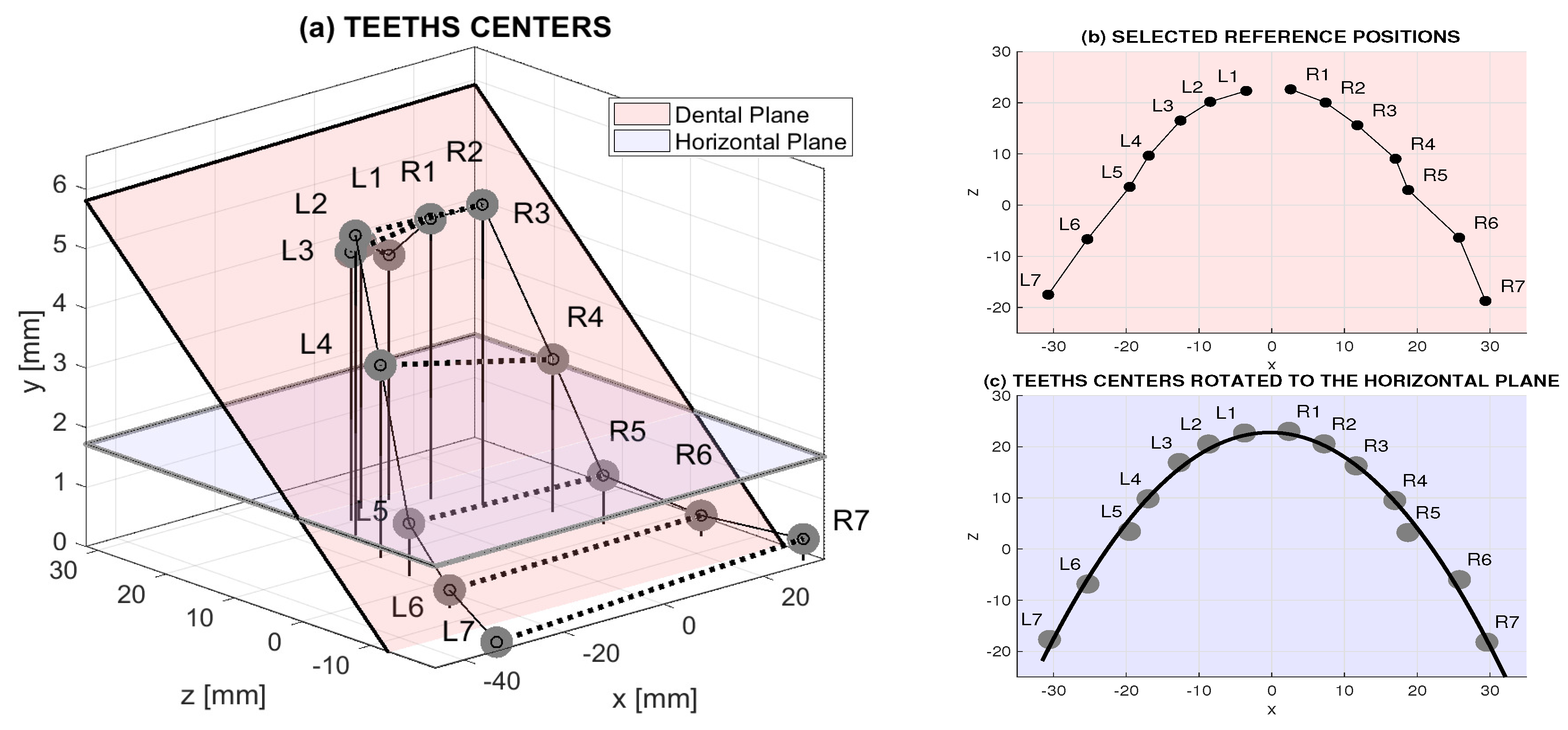
2.2. Data Processing

The proposed algorithm of the processing of point cloud acquired by the intra oral scanner and exported into the STL file includes the following steps:
  • Data acquisition, their visualisation and transform into the 3D space in the selected coordinate system,
  • Data preprocessing using linear and nonlinear filters to reject noise components,
  • Estimation of the dental plane defined by tops of individual teeth using the least square method,
  • 3D data rotation into the horizontal plane and image registration,
  • The use of the digital model for evaluation of selected dental arch parameters.
Data acquired by the intra-oral scanner in the STL format were imported into the computational environment of MATLAB 2018a to reject noise components by median filtering using the moving 5 by 5 mask. The 3D digital model presented in Figure 2b was then processed to find contour levels presented in Figure 2c for a selected tooth (molar).
The contour plot of the acquired dental arch model was used to obtain 3D coordinates of tops of individual teeth to define the dental plane. Its parameters were evaluated by the least square method from these positions. Figure 3a presents the spatial locations of these points related to individual teeth.
The dental plane is in general defined by relation
a ( 1 ) x + a ( 2 ) y + a ( 3 ) z + a ( 4 ) = 0
in the selected Cartesian coordinate system and the coefficients { a ( i ) } i = 1 4 are evaluated by the least square method. The normal vector to this plane and its direction cosines were then evaluated by relation
c o s ( α ) = a ( 1 ) / r , c o s ( β ) = a ( 2 ) / r , c o s ( γ ) = a ( 3 ) / r
for r = s i g n ( a ( 4 ) ) a ( 1 ) 2 + a ( 2 ) 2 + a ( 3 ) 2 defining the angles of the normal vector with positive half-axis in each direction. These angles were then used to find the parameters for rotating all the objects around individual coordinates into the horizontal plane.
To follow the progress of the treatment, it is necessary to compare objects or the complete dental arch of the same individual recorded at different instants. This registration process should be applied to images rotated into the same planes. From the computational point of view, it assumes the combined transform including scaling, rotation, translation and shear of data points { x ( i ) , y ( i ) } into their new position { X ( i ) , Y ( i ) } performed [34,35,36] by matrix multiplication
[ X ( i ) , Y ( i ) , 1 ] = [ x ( i ) , y ( i ) , 1 ] r 1 s 1 0 r 2 s 2 0 r 0 s 0 1
with properly evaluated values of the transform matrix. For the rigid transform, corresponding fixed points in associated images can be selected for specification of the registration.

3. Results

Figure 4a presents a selected 3D digital model acquired by an intra-oral scanner. Details of the right canine and premolar teeth show the selected number of contour levels for visualisation of their shape. The same dental arch after the rotation into the horizontal dental plane is presented in Figure 4b. Details of the contours projected to each tooth were then used for a better localisation of specific teeth regions to estimate their parameters.
Table 1 presents the distances between the corresponding teeth evaluated from the original (O) digital model and from the model after its rotation (R) into the horizontal plane for the lower and upper dental arch. The last row presents coefficients of variations (CV) as a standardized measure of dispersion defined by standard deviations related to mean values. The mean CV was lowered from 0.66% to 0.58% in this case.
Figure 5 presents distances between corresponding objects of the dental arch evaluated from the digital model before and after its rotation into the horizontal dental plane with their mean values. On average, object rotation increases all distances by 0.99 % and 0.8 % for the lower and upper dental arch, respectively. The detailed results are presented in Table 2.
The standard deviation for the upper dental arch is more than double of that of the lower dental arch, which is caused by the more complicated scanning of the upper arch. Both operators were right-handed. When handling the intraoral scanner in the right hand, it is quite difficult to keep continuous scanning of the dental arch and to avoid skipping some places, which may be one of the reasons for the clear difference in standard deviation of measurements of upper and lower dental arch. It is also impossible to control the scanning by direct sight into the oral cavity and the scanning process in the upper jaw is only controlled on the monitor of the scanner itself. In addition, the anatomy of the cheeks and upper dental arch makes it more difficult to handle the scanner in the right position. Finally, some individual variations among patients, for example in shape of hard palate, may influence the comfort and precision of scanning of the upper jaw.
Figure 6a presents the process of registration of the base and input images (on the left and right, respectively) of the same individual rotated to the horizontal dental plane. Results of this registration presented in Figure 6b were used for parabolic approximation of the dental arch by a function
f ( x ) = c ( 1 ) x 2 + c ( 2 ) x + c ( 3 )
for x in the range of minimum and maximum values on the horizontal axes. Distances between symmetrical values of this function evaluated for the base and registered images is lower than 4%.

4. Conclusions

This paper presents a description of the use of an intra-oral 3D scanner for dental data acquisition and of the analysis of dental arch parameters based upon the final digital model. Our results show that the mathematical processing of digital data can reduce the error in the evaluation of dental arch parameters. Moreover, the rotation of digital models into the horizontal plane and their registration can simplify the comparison of scans acquired during the treatment at different time instants.
The object rotation from the dental to horizontal plane increased the evaluated distances by 2.9% in the average for the set of 20 experiments. The proposed methodology enabled (i) to register separate images in the same plane allowing their more simple comparison and (ii) to decrease the variability of results. In the given case, the mean coefficient of variation was lowered by 12%.
The specification of reference points of individual teeth on the surface plot defined by the 3D intra-oral scanner was improved by the contour lines of the surface with their selected density. The contour plots allowed a more precise analysis of the shape of the individual teeth.
Future studies will be devoted to the analysis of more extensive data sets and larger number of patients of different sex and age. Specific studies will be further devoted to the use of digital models for 3D prints [37] of individual teeth and for the selection of appropriate materials during the treatment of possible disorders. The progress of dental materials replacing natural ones is very fast and 3D prints can form an alternative for their use.

Author Contributions

Data curation, S.H.; Investigation, A.P.; Methodology, M.K.; Supervision, T.D.

Funding

This research received no external funding.

Acknowledgments

Real data were kindly acquired at the Department of Dentistry of the Motol University Hospital of the Charles University in Prague. This research has been supported by project 00064203 (FN Motol) and project 54041 (2. LF UK). No ethical approval was required for this study.

Conflicts of Interest

The authors declare no conflict of interest.

References

  1. Kašparová, M.; Gráfová, L.; Dvořák, P.; Dostálová, T.; Procházka, A.; Eliášová, H.; Pruša, J.; Kakawand, S. Possibility of reconstruction of dental plaster cast from 3D digital study models. BioMed. Eng. OnLine 2013, 12, 49. [Google Scholar] [CrossRef] [PubMed] [Green Version]
  2. Bukhari, S.; Reddy, K.; Reddy, M.; Shah, S. Evaluation of virtual models (3Shape OrthoSystem) in assessing accuracy and duration of model analyses based on the severity of crowding. Saudi J. Dent. Res. 2017, 8, 11–18. [Google Scholar] [CrossRef]
  3. van der Meer, W.; Andriessen, F.; Wismeijer, D.; Ren, Y. Application of intra-oral dental scanners in the digital workflow of Implantology. PLoS ONE 2012, 7, e43312. [Google Scholar] [CrossRef] [PubMed]
  4. Wu, J.; Li, Y.; Zhang, Y. Use of intraoral scanning and 3-dimensional printing in the fabrication of a removable partial denture for a patient with limited mouth opening. J. Am. Dent. Assoc. 2017, 148, 338–341. [Google Scholar] [CrossRef] [PubMed]
  5. Barone, S.; Paoli, A.; Razionale, A. Creation of 3D multi-body orthodontic models by using independent imaging sensors. Sensors 2013, 13, 2033–2050. [Google Scholar] [CrossRef] [PubMed]
  6. Vogtlin, C.; Schulz, G.; Jager, K.; Muller, B. Comparing the accuracy of master models based on digital intra-oral scanners with conventional plaster casts. Phys. Med. 2016, 1, 20–26. [Google Scholar] [CrossRef]
  7. Logozzo, S.; Zanetti, E.; Franceschini, G.; Kilpela, A.; Makinen, A. Recent advances in dental optics—Part I: 3D intraoral scanners for restorative dentistry. Opt. Lasers Eng. 2014, 54, 203–221. [Google Scholar] [CrossRef]
  8. Jacob, H.; Wyatt, G.; Buschang, P. Reliability and validity of intraoral and extraoral scanners. Prog. Orthod. 2015, 16, 38. [Google Scholar] [CrossRef] [PubMed]
  9. Dawood, A.; Marti, B.; Sauret-Jackson, V.; Darwood, A. 3D printing in dentistry. Br. Dent. J. 2015, 219, 521–529. [Google Scholar] [CrossRef] [PubMed]
  10. Kašparová, M.; Procházka, A.; Gráfová, L.; Yadollahi, M.; Vyšata, O.; Dostálová, T. Evaluation of dental morphometrics during the orthodontic treatment. BioMed. Eng. OnLine 2014, 14, 68. [Google Scholar] [CrossRef] [PubMed]
  11. Mangano, F.; Gandolfi, A.; Luongo, G.; Logozzo, S. Intraoral scanners in dentistry: A review of the current literature. BMC Oral Health 2017, 17, 149. [Google Scholar] [CrossRef] [PubMed]
  12. Yadollahi, M.; Procházka, A.; Kašparová, M.; Vyšata, O.; Mařík, V. Separation of overlapping dental arch objects using digital records of illuminated plaster casts. BioMed. Eng. OnLine 2015, 14, 67. [Google Scholar] [CrossRef] [PubMed]
  13. Zanetti, E.M.; Bignardi, C. Chapter VI: Structural Analysis of Skeletal Body Elements: Numerical and Experimental Methods. In Biomechanical Systems Technology, Volume 3 Muscular Skeletal Systems; Leondes, C.T., Ed.; World Scientific Publishing Company: London, UK, 2009; pp. 185–225. [Google Scholar]
  14. Procházka, A.; Kašparová, M.; Yadollahi, M.; Vyšata, O.; Grajciarová, L. Multi-camera systems use for dental arch shape measurement. Visual Comput. 2015, 31, 1501–1509. [Google Scholar] [CrossRef]
  15. Yadollahi, M.; Procházka, A.; Kašparová, M.; Vyšata, O. The use of combined illumination in segmentation of orthodontic Bodies. Signal Image Video Process. 2015, 9, 243–250. [Google Scholar] [CrossRef]
  16. Mangano, F.; Veronesi, G.; Hauschild, U.; Mijiritsky, E.; Mangano, C. Trueness and precision of four intraoral scanners in oral implantology: A comparative in vitro study. PLoS ONE 2016, 11, e0163107. [Google Scholar] [CrossRef] [PubMed]
  17. Lee, K. Comparison of two intraoral scanners based on three-dimensional surface analysis. Prog. Orthod. 2018, 19, 6. [Google Scholar] [CrossRef] [PubMed]
  18. Richert, R.; Goujat, A.; Venet, L.; Viguie, G.; Viennot, S.; Robinson, P.; Farges, J.; Fages, M.; Ducret, M. Intraoral scanner technologies: A review to make a successful impression. J. Healthc. Eng. 2017, 2017, 8427595. [Google Scholar] [CrossRef] [PubMed]
  19. Kravitz, N.; Groth, C.; Jones, P.; Graham, J.; Redmond, W. Intraoral digital scanners. J. Clin. Orthod. 2014, 48, 337–347. [Google Scholar] [PubMed]
  20. Martin, C.; Chalmers, E.; McIntyre, G.; Cochrane, H.; Mossey, P. Orthodontic scanners: What’s available? J. Orthod. 2015, 42, 136–143. [Google Scholar] [CrossRef] [PubMed]
  21. Nedelcua, R.; Olssonb, P.; Nyströmb, I.; Rydénc, J.; Thora, A. Accuracy and precision of 3 intraoral scanners and accuracy of conventional impressions: A novel in vivo analysis method. J. Dent. 2018, 69, 110–118. [Google Scholar] [CrossRef] [PubMed] [Green Version]
  22. Logozzo, S.; Kilpel, A.; Makynen, A.; Zanetti, E.M.; Franceschini, G. Recent advances in dental optics—Part II: Experimental tests for a new intraoral scanner. Opt. Lasers Eng. 2014, 54, 187–196. [Google Scholar] [CrossRef]
  23. Zarauz, C.; Valverde, A.; Martinez-Rus, F.; Hassan, B.; Pradies, G. Clinical evaluation comparing the fit of all-ceramic crowns obtained from silicone and digital intraoral impressions. Clin. Oral Investig. 2016, 20, 799–806. [Google Scholar] [CrossRef] [PubMed]
  24. Rivera-Ortega, U.; Dirckx, J.; Meneses-Fabian, C. Fully automated low-cost setup for fringe projection profilometry. Appl. Opt. 2015, 54, 1350–1353. [Google Scholar] [CrossRef] [PubMed]
  25. Koopaie, M.; Kolahdouz, S. Three-dimensional simulation of human teeth and its application in dental education and research. Med. J. Islam Repub. Iran 2016, 30, 461. [Google Scholar] [PubMed]
  26. Hošťálková, E.; Vyšata, O.; Procházka, A. Multi-dimensional biomedical image de-noising using Haar transform. In Proceedings of the 15th International Conference on Digital Signal Processing, Cardiff, UK, 1–4 July 2007; pp. 175–179. [Google Scholar]
  27. Jerhotová, E.; Švihlík, J.; Procházka, A. Biomedical Image Volumes Denoising via the Wavelet Transform. In Applied Biomedical Engineering; INTECH: London, UK, 2011; pp. 435–458. [Google Scholar]
  28. Chun, J.; Tahk, J.; Chun, Y.; Park, J.; Kim, M. Analysis on the accuracy of intraoral scanners: The effects of mandibular anterior interdental space. Appl. Sci. 2017, 7, 719. [Google Scholar] [CrossRef]
  29. Hong-Seoka, P.; Chintal, S. Development of high speed and high accuracy 3D dental intra oral scanner. Procedia Eng. 2015, 100, 1174–1181. [Google Scholar] [CrossRef]
  30. Ahn, J.; Park, A.; Kim, J.; Lee, B.; Eom, J. Development of three-dimensional dental scanning apparatus using structured illumination. Sensors 2017, 17, 1634. [Google Scholar] [CrossRef] [PubMed]
  31. Logozzo, S.; Franceschini, A.; Kilpela, A.; Caponi, M.; Governi, L.; Blois, L. A comparative analysis of intraoral 3D digital scanners for restorative dentistry. Internet J. Med. Technol. 2011, 5, 1–18. [Google Scholar]
  32. Cali, M.; Oliveri, S.M.; Ambu, R.; Fichera, G. An Integrated Approach to Characterize the Dynamic Behaviour of a Mechanical Chain Tensioner by Functional Tolerancing. J. Mech. Eng. 2018, 64, 245–257. [Google Scholar]
  33. Nedelcu, R.; Olsson, P.; Nystrom, I.; Thor, A. Finish line distinctness and accuracy in 7 intraoral scanners versus conventional impression: an in vitro descriptive comparison. BMC Oral Res. 2018, 18, 27. [Google Scholar] [CrossRef] [PubMed]
  34. Goshtasby, A. Image Registration: Principles, Tools and Methods; Springer: Berlin, Germany, 2012. [Google Scholar]
  35. Hajnal, J.; Hawkes, D.; Hill, D.; Hajnal, J. Medical Image Registration; CRC Press: Boca Raton, FL, USA, 2001. [Google Scholar]
  36. Modersitzki, J. Numerical Methods for Image Registration; Oxford University Press: Oxford, UK, 2003. [Google Scholar]
  37. Zanetti, E.M.; Aldieri, A.; Terzini, M.; Calì, M.; Franceschini1, J.; Bignardi, C. Additively manufactured custom load-bearing implantable devices: grounds for caution. Aust. Med. J. ASM 2017, 10, 694–700. [Google Scholar]
Figure 1. Principle of 3D intra-oral scanning (using a handheld camera and a computer system) device (Trios/3shape) for data acquisition and for the 3D model construction: (a) 3D scanning; (b) Data processing steps.
Applsci 08 01838 g001
Figure 2. The processing steps of the point cloud data acquired by the intra oral scanner including visualisation of the STL data, their transform to the spatial model in the selected coordinate system and the detailed molar contour plot allowing detection of specific surface areas: (a) STL model; (b) 3D spatial model; (c) Molar contour plot.
Applsci 08 01838 g002
Figure 3. Data processing presenting: (a) original centers of separate teeth acquired by the 3D scanner in the 3D space with the original and rotated plane, (b) original centers of separate teeth in the 2D space, (c) rotated centers of separate teeth in the 2D space with their approximation by a polynomial of the second order.
Applsci 08 01838 g003
Figure 4. Digital model of a selected observation presenting (a) original 3D dental arch and (b) rotated object.
Applsci 08 01838 g004
Figure 5. Mean distances between corresponding objects of the dental arch evaluated from the digital model before (O) and after its rotation (R) into the horizontal dental plane.
Applsci 08 01838 g005
Figure 6. The process of registration of the base and input images (on the left and right of (a), respectively) and result of registered images of the same individual: (a) Image registration with selected fixed points; (b) Two lower dental arches (2a.stl and 3a.stl) registered by fixed points.
Applsci 08 01838 g006
Table 1. Distances between corresponding teeth evaluated from the original (O) digital model and from the model after its rotation (R) into the horizontal dental plane for the lower and upper dental arch with coefficients of variations (CV) in the last line.
Lower Dental Arch Distances [mm] Upper Dental Arch Distances [mm]
Exp.L3-R3L4-R4L5-R5 L3-R3L4-R4L5-R5
OROROR OROROR
124.4324.4534.1434.4038.1738.29 35.1935.2342.5942.6150.0850.09
224.3824.4733.8234.2038.1938.90 35.0635.6742.6343.0649.6550.14
324.2424.7433.8634.0537.6938.51 35.1635.2142.1642.2750.1250.37
424.4524.5033.6034.2737.7338.24 34.8935.3042.3142.4349.1749.28
524.3724.4333.8434.0937.4738.37 35.1735.6842.1942.8649.6049.34
624.1424.3834.0834.3137.8838.39 35.0835.2842.3842.4550.1350.41
724.1724.4233.7834.0937.6438.36 34.8535.6242.3642.5849.0550.94
824.1624.3634.1734.2438.0738.66 34.9835.4342.4342.6749.6250.02
924.2624.5634.1734.1538.1638.62 34.6135.0342.4842.5449.1149.45
1024.4324.4734.1634.2138.3138.56 35.1535.3642.5542.7149.8649.94
1124.1424.4734.1134.1638.0738.24 34.7635.0642.1342.2349.4750.29
1224.1124.7333.6734.1737.6738.61 34.1634.1841.8243.0549.0349.68
1324.4624.5834.0934.1838.1038.44 35.1235.1742.5942.8250.1650.26
1424.1924.6433.9234.0238.0138.70 35.3235.5741.7542.5349.9149.99
1524.2624.6334.1234.2937.9638.77 34.5235.9442.5442.6149.8650.18
1624.3524.4534.1334.1538.0438.24 35.0235.1342.4042.8649.7349.84
1724.2924.3634.0134.1338.1138.62 34.9335.2742.8142.9150.0850.13
1824.1924.6733.9634.2837.9138.44 35.2635.5841.7641.9749.2349.55
1924.3824.4134.0834.3737.8738.49 34.6434.8342.5542.7849.4250.14
2024.2724.4234.0134.3638.0838.68 34.2134.6742.2342.3949.8849.92
MEAN:24.2924.5133.9934.2137.9838.51 34.9035.2642.3342.6249.6650.00
STD:0.120.110.170.110.190.19 0.330.280.300.280.390.40
CV [%]:0.490.450.500.320.490.49 0.950.790.710.660.790.80
Table 2. Mean distances between corresponding teeth and their standard deviations evaluated from the digital model after its rotation into the horizontal dental plane for the lower and upper dental arch with their percentage changes caused by rotation.
Lower Dental Arch Measures Upper Dental Arch Measures
L3-R3L4-R4L5-R5 L3-R3L4-R4L5-R5
MEAN [mm]:24.5134.2138.51 35.2642.6250.00
MEAN change [%]:+0.91+0.65+1.40 +1.03+0.69+0.68
STD [mm]:0.110.110.19 0.280.280.40
STD change [%]:−8.33−35.290 −15.15−6.67+2.5

