Article

Correcting Inertial Dead Reckoning Location Using Collision Avoidance Velocity-Based Map Matching

1
Faculty of Fire Safety Engineering, The Main School of Fire Service, 01-629 Warsaw, Poland
2
Faculty of Physics, Astronomy and Informatics, Nicolaus Copernicus University, 87-100 Torun, Poland
*
Author to whom correspondence should be addressed.
Current address: Faculty of Fire Safety Engineering, The Main School of Fire Service, Slowackiego 52/54, 01-629 Warsaw, Poland
Appl. Sci. 2018, 8(10), 1830; https://doi.org/10.3390/app8101830
Submission received: 23 August 2018 / Revised: 19 September 2018 / Accepted: 29 September 2018 / Published: 6 October 2018

Abstract

:

Featured Application

This paper contributes to the domain by proposing a new approach for inertial navigation systems error correction, based on collision avoidance velocity. The approach can be beneficial for navigation systems when an individual is moving close to building obstacles. Close proximity to building obstacles is encountered in firefighting during search and rescue operations in smoky compartments. Thus, the main goal of the algorithm is to improve the indoor navigation system for firefighters.

Abstract

We propose an algorithm for map-aided inertial dead reckoning (DR) for indoor navigation. The technique is based on a concept of collision avoidance velocity. New positions estimated by DR are checked for collision detection with walls and if such a situation is detected, the collision avoidance velocity is calculated to avert the obstacles. The differences between an individual’s indicated velocity and collision avoidance velocity are then used to correct errors for further path development. The best performance of the proposed technique is achieved when the individual moves along building obstacles. This type of movement is typical for firefighters, during search and rescue operations in thick smoke. Such conditions provided the environment for testing our algorithm.

1. Introduction

The fatality rate of firefighters is still at a high and unacceptable level. For the last 10 years, despite improvement in procedures, equipment and protective gear, there are still, on average, 60 firefighter deaths annually in the United States of America [1]. Due to this fact and the high respect that societies hold for the firefighter occupation, the social pressure has increased to find solutions that increase firefighter safety. The social willingness to protect firefighters is manifested in a form of various funding focused on seeking a solution to the problem in question through new technologies. One such societal initiative is Chief J. Burs Memorial Research Grant (http://foundation.sfpe.org/chief-donald-j-burns-memorial-research-grant).
Our contribution to the field, as a recipient of this grant, is based on the analysis of contributing factors which lead to the unsafe events. The Firefighter Near-Miss (http://www.firefighternearmiss.com/) is an organization which aims to prevent injuries and save the lives of firefighters by collecting, sharing and analyzing unintentionally unsafe events. According to the annual reports provided by this organization, 28.5% of casualties were caused by communication problems or by bad situational awareness [2].
Situational awareness, as described above, corresponds to the amount of attention and understanding of the actual state of the environment. Conditions affecting situational awareness can be broken down into three groups: a lack of information, a lack of knowledge and a lack of cognition. Therefore, the reasons underlying incorrect assessment of the situation correspond to more general problems related to acquisition and processing of relevant information. The position of firefighters in danger zones is reported as the most relevant information for the proper assessment of the situation [2].
Our goal, defined within this grant, was to design an indoor navigation system for firefighters that may fill the information gap related to firefighter positioning. We decided to address this problem by developing an Inertial Dead Reckoning approach.
Inertial Dead Reckoning is a process of calculating the current position of a individual, using the previous position estimates and based purely on the readings of inertial sensors [3]. Modern solutions for individual navigation exploit mostly foot-mounted Micro Electro Mechanical Sensors (MEMS), that are able to gather acceleration and angular rates with high sampling rates and high precision. The basic theory of their operation relies on double integration of recorded acceleration force rotated in a navigational frame of reference, estimated using gyroscope integration. Most of the time, the navigation algorithm is expressed by means of the Kalman Filter with an additional Zero-Velocity update technique [4], that uses a simplified model of walk to reduce computational errors. This technique is proven to be effective in many reports [5,6,7,8,9,10]. Nevertheless, due to sensor drift, measurement errors and floating point precision, the error in such an Inertial Navigation System (INS) accumulates over time [11] and therefore additional corrections are required.
One of the possible approaches to correct INS positioning is the use of an infrastructure-based positioning system (GPS is a good example) or short range radio infrastructure such as WiFi or Bluetooth Low Energy (BLE) [12,13]. Radio-based solutions use a number of techniques from Received Signal Strength Indicator (RSSI) mapping, Time-of-Flight (ToF) solutions combined with triangulation or machine learning approaches. The idea behind the integration of INS and infrastructure-based solutions arises from different error models [14], and the capability of mutual error correction based on systems’ characteristics. INS has small but accumulative error, while infrastructure-based systems have significant but constant error.
There are, however, shortcomings of these methods of error correction. A GPS signal is, in most cases, not received indoors. The radio beacons must be present before a fire starts in a building. Preparing the radio beacon infrastructure just in case of a fire is economically debatable because of the rare occurrence of fire and the special operational requirements—fire resistance and an alternative source of power. During search and rescue operations, exploiting this type of positioning system could be limited due to electricity loss or temperature damage.
The other set of approaches for error correction becomes available when the layout of a building is accessible [15,16,17]. Progress in building design means that the majority of buildings are currently designed in Building Information Modeling technology (https://en.wikipedia.org/wiki/Buildinginformationmodeling). Having such a vast source of information related to the building (where the navigation takes place), we can create a set of rules and constraints to better navigate the firefighter in the building. The algorithms that match a sequence of observed user positions to a digital map of the building or, in general, the real world, are grouped under a common umbrella called Map-Aided navigation.
The task of map-matching is to determine a correspondence between sequences of previously obtained user position points (e.g., from GPS) and a given map. The main application of Map-Aided algorithms is fixing data obtained from a Global Navigation Satellite System, into a spatial road network for car navigation. However, the idea of using building geometry for heading errors in positioning systems is also extensively exploited.
In the case of pedestrian indoor navigation, building floor plans are transformed into a representation that expresses traversable areas. For example, people cannot walk through walls and floor changes can occur only via staircases or elevators. There are currently three approaches to map-aided navigation indoors [18]: (a) probabilistic map matching based on particle filtering using wall constraints, (b) topological map matching based on link-node representation of a building plan and (c) reduction of heading error by comparison with building cardinal heading.
In this article, we propose an algorithm for map-aiding which uses wall constraints. However, due to the fact that most of the error pruning in our INS is angular rate estimation, we decided to apply a velocity-based correction approach instead of particle filtering. The core of the concepts in our approach is velocity obstacle and collision avoidance velocity.
This paper contributes to the domain by proposing a new approach for INS error correction, based on collision avoidance velocity. The approach can be beneficial for the problem of moving an individual who is close to building obstacles. Close proximity to building obstacles is encountered in firefighting during search and rescue operations in smoky compartments [19]. Thus, the main goal of the algorithm is to improve the indoor navigation system for firefighters.
Map-aided correction techniques were invented for vehicle dead reckoning in 1984 [20]. Since then, a substantial amount of research has been conducted in order to address problems of map-matching for vehicle navigation. The majority of the available solutions focus on correcting routes from GPS. According to a previous survey [21], we can categorise general approaches for map-matching algorithms presented in the literature into four groups: geometric, topological, probabilistic and other advanced method. In this domain, the problems faced are not only related to the algorithm itself but also data structure to store the map in a computationally effective manner [21].
The most commonly used geometric map-matching algorithm is a simple search algorithm. In this approach, each position fix is matched to the closest ‘node’ or ‘shape point’ of a road segment. This is known as point-to-point matching [22]. More general approaches exploit ‘point-to-curve’ or ‘curve-to-curve’ matching [22,23,24] using trajectory estimated from consecutive GPS fixes as the candidate route. In [25,26] the development of the path is computed by INS/GPS combination. Those techniques exploit the general idea of mapping a path obtained by different systems (with possible accumulative and constant error) with possible route shapes encoded by a map. Unfortunately, in indoor environments, the number of possible routes is unbounded; therefore, the possibility of direct application of those techniques in individual navigation systems is substantially limited.
Map-Aided Pedestrian/Individual Navigation (MAPN) is more challenging than vehicle map-aided navigation. Most of the time, we cannot assume constraints on a path—humans can take sudden turns and accidental stops, whereas a car needs to be bounded with maneuvering constraints. Moreover, since the acceleration characteristics of vehicles are less rapid, the error of these INSs is more bounded, which eventually results in better path estimation.
Simple derivation of the ‘curve-to-curve’ matching technique for MAPN is illustrated in [15]. To compensate for the inaccuracies in step detection and heading estimation, the authors matched the detected step series onto the expected route using a sequence alignment algorithm outputting the ‘best fit’. This method is convenient only when a mobile device is navigating a pedestrian over the path (therefore, we know the expected route).
A substantial amount of research exploits Particle Filters for MAPN to address high non-linearity in human movement [16,17,27,28,29,30]. For example, ref. [7] uses an on-line technique for particle weighting which is based on a transition map between hexagonal map division ‘cells’. Nevertheless, this approach assumes frequent re-visiting of ‘cells’ to achieve a bounded positioning error. The authors of [31] introduce the Cardinal Heading Aided Inertial Navigation (CHAIN)—a technique in which particles are weighted or ‘killed’, eliminating impossible states based on building walls. CHAIN uses four cardinal moves and heuristics based on the building structure to obtain the most possible heading correction (it is important to note that heading error is crucial in pedestrian INS). In [32], the authors exploit a similar technique but instead of assuming heading based on the wall structure, the authors trained a Hidden Markov Model to express ‘human behavior’ in movement. In [33], the authors introduce substantial optimization for particle filters exploiting indoor maps in this specific application.
The particle filter is most commonly used for MAPN because it provides a straight-forward, formally clean method of exploiting the error covariance matrix from the Kalman Filter—the particles reflect possible paths in which the probability is inherited from error modelling. Nevertheless, when the path does not cross any obstacles, a great number of possible paths (particles) need to be maintained for longer periods and the whole technique becomes a computationally demanding algorithm. Consequently, exploiting it on mobile devices can be limited by power supplies. Our work is very similar to that of [31,32] but instead of maintaining all possible paths, we assumed very specific path traversal behaviour of firefighters.

2. Materials and Methods

This section describes the algorithm for matching the position of the firefighter to the building layout. In order to be consistent with the terminology presented in Section 1, we use the term individual instead of firefighter. However, in this case, the individual has a specific movement pattern consistent with firefighters’ movement during search and rescue operations. We also introduce the term software agent (or agent for short) which is the reflection of the individual in the computer program. Our definition of the agent is consistent with that presented in [34].
The goal of the algorithm is to minimize the location error by the map-aiding approach. The algorithm updates the velocity vector of an individual by finding the closest collision free velocity to the current velocity. The updates in velocity are recorded and then used to correct the incoming positions.
Our main assumption in the selection of a map-matching algorithm is based on the collision avoidance velocity, derived from a firefighting tactic. This tactic suggests that in dense smoke with low visibility, firefighters should move along walls, maintaining hand contact with them [19]. The left-hand rule in this situation is also recommended (or at least the same hand all the time).
The observation of the movements of firefighters during our blind tests confirms that individuals tend to apply this left-hand rule. They move along the walls while maintaining contact with them. Therefore, we decided that our algorithm will be based on the proximity of walls. We assumed that the walls will be a source of correction of the firefighter’s position.
The tests of our generic INS (without additional error correction) revealed that the error increases with the number of rotations performed by individuals. The bigger the number of rotations, the bigger the error. Even when individuals try to move in a straight line, small sway of their feet causes deviation from the course. The reflection in the rotation is very important because small error in the angle of rotation causes large error in the position. This was especially reflected in the long walks, causing significant error in the location. Figure 1 depicts the situation where small error in angle reflection causes large error in location.
The main idea is to estimate the inter-step path reconstructed by INS and correct it by local collision detection and a collision avoidance velocity algorithm. Collision detection needs to be accomplished with regards to the current position and formal definition of a map. Next, the smallest possible correction of agent velocity is performed to avoid the obstacle. The velocity vector is defined as subtraction of the last position obtained from INS and the current agent position.

2.1. Foot-Mounted Inertial Navigation System

Foot-Mounted INS is implemented by means of the Kalman Filter by estimating an error state vector δ x k = [ δ v k , δ p k , δ C k ] , which represents errors in velocity, position and orientation matrix, respectively, at time k. The input vector is formed from sensor readings u k = [ a k , ω k ] , which represent acceleration a k = [ a x k , a y k , a z k ] and angular rates ω k = [ ω x k , ω y k , ω z k ] both in the sensor frame of reference. Note that we operate on quaternions in navigation equations, which are later converted to the orientation matrix in error state computations. Therefore, u k does not match the transition state matrix but is converted by the control-input model described in detail in pseudocode.
Details of the algorithm are described by pseudocode Algorithm 1. Generally, we maintain a quaternion q k that rotates from the sensor frame of reference to the navigational frame estimated by some orientation filter (e.g., [35]) using ω k (line no. 7). Then, we compute acceleration in the navigational frame (line no. 8) to apply mechanization equations (lines 9–10). In line 17, the error is computed using Kalman Gain K using zero velocity pseudo-observation (note the observation matrix H). This is pseudo-observation because we do not measure it directly but use some statistical hypothesis to test whether the feet are still in function IsZUPT (for possible implementations, see [36]. Briefly speaking, one can check whether raw readings from a gyroscope or accelerometer are below a certain threshold).
State transition matrix F k is defined as follows:
F k : = I 3 × 3 Δ t I 3 × 3 0 3 × 3 0 3 × 3 I 3 × 3 0 3 × 3 Δ t S k 0 3 × 3 I 3 × 3 ,
where S k is a skew-symmetric cross-product operator matrix given by:
S k : = 0 - a z , k N a y , k N a z , k N 0 - a x , k N - a y , k N a x , k N 0 .
Algorithm 1 Pseudocode for the inertial positioning system with zero-velocity updates and collision avoidance velocity map matching.
1:
procedure INS-MM( a , ω , g 0 , A )
2:
     k 0
3:
     q 0 INITIALIZE ORIENTATION ( g 0 )
4:
     p l , k l 0 , 0
5:
    loop
6:
         k k + 1
7:
         q k UpdateOrientation( a k , ω k )
8:
         a n a v q k - 1 a k q k - g 0
9:
         v k ( + ) v k - 1 + a n a v Δ t
10:
         p k ( + ) p k - 1 + v k - 1 Δ t
11:
         x p ( + ) [ v k ( + ) p k ( + ) QuatToRotMtx( q k ) ]
12:
         P k ( + ) = F P k - 1 F T + Q
13:
        if IsZUPT( ω , k ) then
14:
            H [ 0 3 × 3 I 3 × 3 0 3 × 3 ]
15:
            K P ( + ) H T ( H P ( + ) H T + R ) - 1
16:
            P k I - K H P k ( + )
17:
            [ δ v k δ p k δ C k ] K ( 0 3 × 1 - H x k )
18:
            q k CorrectOrientation( C k )
19:
            [ p k , v k ] [ p k , v k ] - [ δ p k , δ v k ]
20:
            v a ( p k - p l ) k Δ t
21:
            p l , k l p k , k
22:
           if IsCollision( p k , A ) then
23:
                θ k O R C A ( v a , A )
24:
                q k q k q θ k
25:
           end if
26:
        end if
27:
    end loop
28:
end procedure

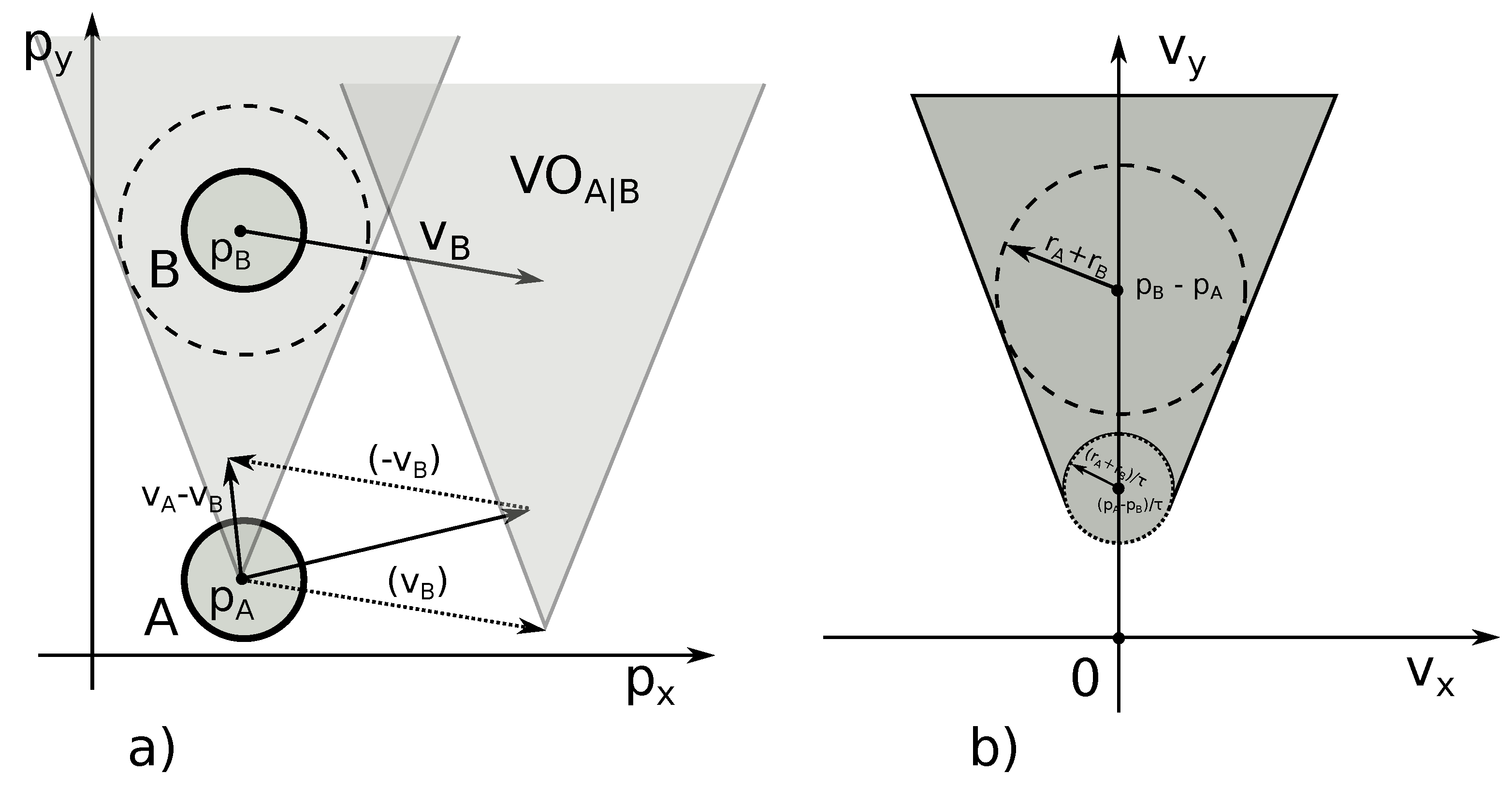
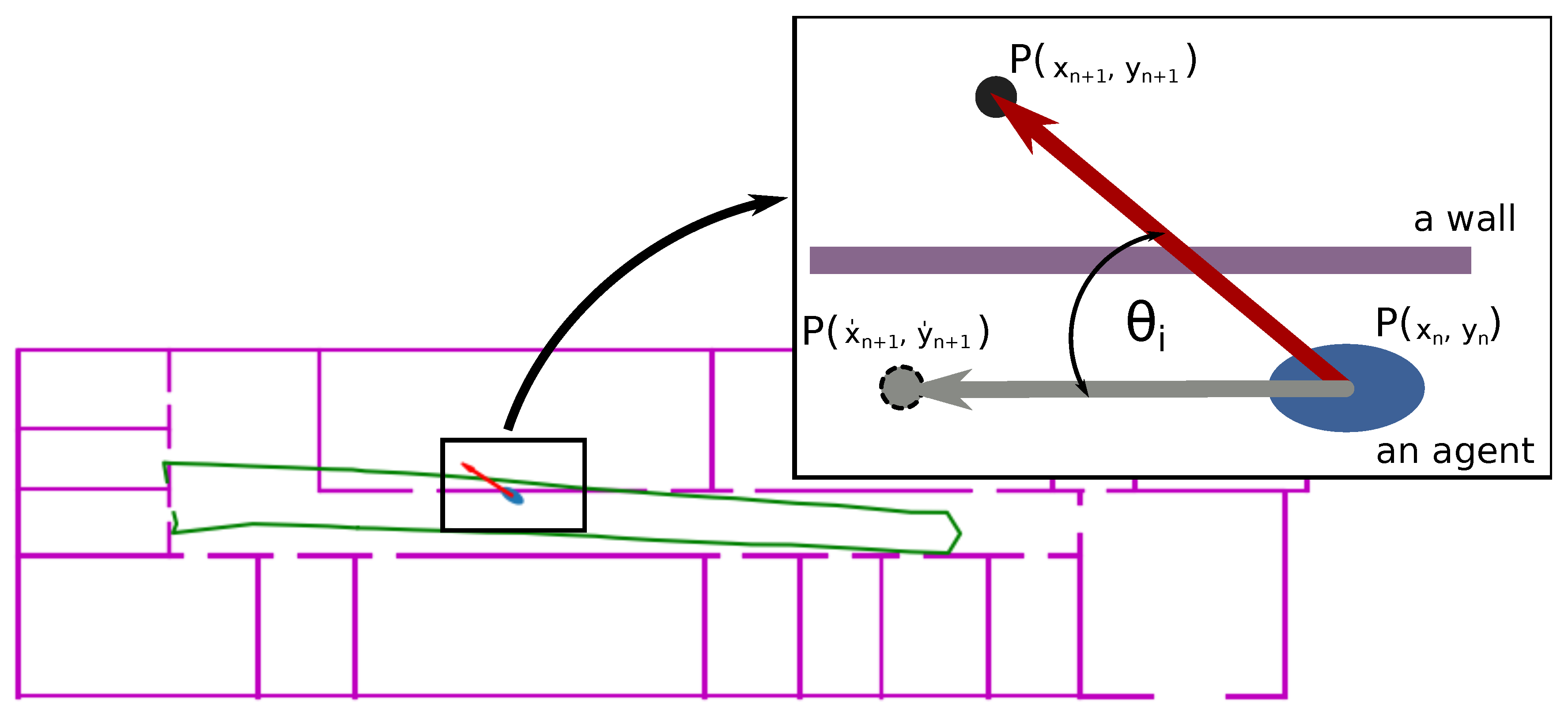
2.2. Collision Avoidance Velocity

The data obtained from INS are then fitted to the building layout by using our map-matching algorithm. We try to correct the error of rotation using walls as boundaries.
The movement of an individual can be defined by a velocity vector, broken down into orientation and length. The orientation reflects the direction of the movement while the length reflects the speed along this direction. Our idea for map-matching is to record the changes in the orientation of the velocity vector imposed by collision avoidance.
The intuition of the algorithm is as follows. For each step of the individual, we define an orientation of the velocity vector by subtraction of the new position coming from radio equipment and the position previously recorded. If the velocity vector collides with a wall, we calculate the change in angle of the orientation of the velocity vector needed to avoid collision with the wall. The change is stored in an update matrix and each subsequent step of the individual is then corrected according to these saved changes.
The velocity obstacle, as well as the collision avoidance velocity calculation, is based on the Optimal Reciprocal Collision Avoidance (ORCA) algorithm proposed in [37]. The algorithm is widely discussed in [37,38,39]. However, for the sake of clarity, let us briefly present this algorithm.
The algorithm aims to avoid the velocity obstacle ( V O ). The velocity obstacle is the set of all velocities of an agent that will result in a collision with another agent or an obstacle. Due to the ambiguity of concepts used in VO, let us describe the approach using formal notation.
Let A = { A 1 , , A n , , A N } be the set of N agents sharing the same R 2 plane. Any agent A n from A is represented by a disc with its center at position p n and radius r n . The obstacles are defined as rectangles by four points in counter-clockwise order. However, they are also projected onto the disc with its center at p n and radius r n . Hence, discussing collision avoidance among agents does not differ from discussing collision avoidance between an agent and an obstacle. However, for the sake of this article, keeping these concepts together does not introduce much complexity.
The velocity obstacle V O A n | A k τ for an agent A n induced by an agent A k for some time window τ is the set of all velocities that result in a collision of the agents at some moment before time τ  [39]:
V O A n | A k τ = { v | t [ 0 , τ ] : : t v D ( p k - p n , r n + r k ) } ,
where D ( p , r ) represents a disc with center p and radius r. Figure 2 depicts the geometric interpretation of the velocity obstacle.
In the ORCA algorithm, V O is calculated as a Minkowski sum A n A k of two objects representing agents A n and agent A k , and object - A n reflecting its reference point:
A n A k = { a n + a k | a n A n , a k A k } , - A n = { - a n | a n A n } .
There is a ray λ from p n in the direction of the relative velocity of A n and A k ( v n - v k ) . If the ray intersects the Minkowski sum of A k and - A n centered at p k , then v n is the velocity obstacle of agent A n induced by agent A k :
V O A n | A k = { v n | λ ( p n , v n - v k ) A k - A n } ,
then, for any v m V k and v n V O A n | A k τ V B , A n and A k are guaranteed to be collision-free at their current velocities for at least time τ . The collision avoiding velocity is defined as follows:
C A A n | A k τ ( V k ) = { v | v V O A n | A k τ V k } .
The goal of the ORCA algorithm is the calculation of the collision-avoiding velocities for agents A n and A k within the time τ .
There are additional assumptions for ORCA algorithms. Each of the agents is aware of other agents’ parameters: their current position p n , current velocity v n and radius r n . Each of the agents also has some private parameters: maximum speed v n m a x and a preferred velocity v n p r e f . A preferred velocity is the velocity the agent assumes without any collision with obstacles or other agents.
There is an infinite number of pairs of velocities v n and v k that are collision-avoiding. ORCA selects the pair that is close to v n p r e f and v k p r e f velocities of the agents. ORCA finds the smallest change u required to the relative velocity ( v n - v k ) to avert collision within time τ .
The overall approach is as follows. Agent A n performs a continuous cycle of sensing and acting with time step Δ t . In each iteration, the agent acquires the radius, the current position of the agents (and of itself). Based on this information, the A n infers the permitted plane of velocities C A A n | A k τ with respect to A k .
In the case of INS error correction, the simulated agent is the agent who should be navigated. We obtain the position for each step of the agent and try to calculate the velocity for inner-steps. The agent needs to be guided along the path defined by radio equipment. For each step performed by the agent, a new position comes to the algorithm. The velocity vector and speed (scalar) are calculated by subtraction of the position coming from radio equipment and the previous position of the agent.
For the location of agents inside the building, we create a simulation environment that consists of the following: (a) an agent A n , where p n is the center of the disc representing the agent and r n is the radius of the agent n; (b) a set of obstacles; (c) a set of M positions from radio equipment O = { O 1 , , O m , , O M } .
Since the agent in the software should reconstruct the path of the individual in the real environment, the velocity of the individual and the agent must be the same. The average stepwise velocity of the individual is measured, and set as the preferred velocity v n p r e f to the agent.
The stepwise velocity of the individual is calculated by subtracting the last position O m and last but one position of the individual coming from radio equipment O m - 1 divided by the difference of the timestamps of these positions.
v n p r e f = O m - O m - 1 t O m - t O m - 1
The general idea of error correction is advancing (when necessary) the agent’s v n p r e f , on the basis of positions coming from radio equipment; then, checking whether they collide with an obstacle. If this case holds, we calculate the collision avoidance velocity and correct navigation.
The algorithm should be aware of building obstacles. Therefore, at the beginning, the geometry of the environment (where the localisation takes place) should be defined. An open source library from project Aamks (http://github.com/aamks) is utilized for this purpose. The library contains a CAD plug-in that allows for drawing building layout in AutoCAD. Then, using the same library, the AutoCAD drawing is transformed into a set of cuboid obstacles. Each of the cuboids is defined by the four-tuple coordinates. The output from the library is a json file as presented below:
obstacles": {
    "1": [
      [ [ 1394, 994 ], [ 1500, 994 ], [ 1500, 990 ], [ 1394, 990 ] ],
      [ [ 1135, 990 ], [ 1014, 990 ], [ 1014, 994 ], [ 1135, 994 ] ],
     ...
}
In this file, “1” reflect the floor of the building and contains obstacles at this floor. The json file is then imported to the algorithm, creating the obstacles for the agent.
The next step is to import of data from electronic devices. The data coming from INS constitute the following frame: timestamps of the step, x , y , z position and the distance of the agent from an anchor (the anchor is defined in Section 3.1).
timestamp , x      , y      , z      , distance
750286    , -0.001 , -0.001 , -0.000 , {1: 0.78}
756754    , 3.173  , 0.372  , 0.198  , {1: 4.46}
757815    , 4.512  , 0.648  , 0.254  , {1: 5.77}
758939    , 5.950  , 0.792  , 0.340  , {1: 7.12}
759945    , 6.563  , 0.851  , 0.343  , {1: 7.69}
In the navigation process, we address agent position on 2D space. The z coordinate is excluded from error correction, and is used as an elevation parameter. There is no collision detection with ceilings or floors.
The positions returned from radio equipment are calculated as a relative distance from the starting point of the agent (start of the navigation). The starting position is always (0, 0, 0). Let us call this system a local coordinate system (LCS). The first step in INS is always advancement in all coordinates. Hence, LCS can be rotated, depending on the direction in which the individual starts moving.
There is also a global coordinate system (GCS), the system where the building is situated, defined for example by the GPS position. In order to visualize the agent on the building layout, it is necessary to translate and rotate LCS to adjust GCS. We assume that this operation will be performed when INS is working and the data from GNSS are still available (at the entrance to the building). The translation and rotation operation is stored in an update matrix defined as follows:
c o s θ - s i n θ d x s i n θ c o s θ d y 0 0 1
where d x , d y is a translation vector and θ is the angle of rotation.
Hence, the adjustment of LCS to GCS will be based on the following calculations:
x g y g = c o s θ - s i n θ d x s i n θ c o s θ d y 0 0 1 · x l y l 1
where x g , y g are coordinates in GCS and x l , y l are coordinates in LCS.
The transformed points from LCS are then used to calculate the average stepwise velocity of the individual, and then set to the agent. Then, the agent moves to the transformed position coming from INS. The operation is repeated for each of the consecutive positions coming from INS. Figure 3 depicts the positions coming from radio INS. Between each consecutive pair of points, we calculate the velocity of the individual and place it in the simulation environment.
The operation is repeated during the entire navigation process, guiding the agent through the building. When the calculated velocity (on the basis of the current and next position of the individual) collides with a wall, ORCA corrects the velocity vector. The proposed position avoids the obstacles and is defied by a new velocity with collision avoidance. Then, the angle between INS-defined velocity and collision avoidance velocity is calculated. The angle constitutes an update for navigation. Figure 4 shows how the angle of update is calculated.
The angle of update θ i needed to avoid collision with an obstacle is then used to change the value in the defined update matrix. Then, each of the following positions is updated according to these corrections. The final algorithm for error correction is presented in pseudocode Algorithm 1.
Additional assumptions are required as not all the collisions were caused by INS error in rotation. Some of them were caused by error in the distance calculation, eventually missing the proper doors.
In order to discover that the error is due to a bad reflection in rotation, we assume that this type of error generates a rather small update in angle θ i . This means that if θ i is, for example, 90, this is not an error in rotation, but rather some other problem. This means that an agent most likely crossed a door; however, due to the error in location, we missed this door. Therefore, we assumed a range of accepted angles that may be caused by the error in rotations.
On the basis of the experiments, we decided that the maximal error for one step caused by the inertial system is no greater than 30°. Hence, if the algorithm calculates that the correction in velocity—needed to avoid a wall—is less than 30°, it places the update in the update matrix. The final tuning of the threshold value can be defined on the basis of genetic algorithms. This is a goal for future work.
For the sake of performance, we are also going to avoid having an excessively long update matrix. Therefore, we also defined experimentally a lower boundary for the update error. We decided to place the update in the matrix if it is greater than 2°.
The other assumption related to the velocity angle value that needed to be corrected is that, if this correction is around 90 ° ± 15 ° we suspect that the agent transits compartments; however, we miss the proper door. In this case, we should move the agent position to a door. This is performed by updating the values of the transformation vector ( d x , d y ) in the update matrix. The vector is defined on the basis of the current agent’s position and the door center position defined in the building layout.
In many cases, due to error in the location, it is not obvious which door should be chosen. It appeared that choosing the closest door is misleading—from the perspective of the current location of the agent. In an office layout, where a number of doors are placed very close to each other, the choice of the closest door was a source of poor navigation.
To address this problem, we used second information sent by INS—distance of the agent from an anchor. We assume that when an agent enters a building, they place the anchor at the entrance. The anchor is used to calculate the point-to-point distance between the receiver worn by an agent, and the anchor. The door selection problem was addressed by minimizing the error in distance with respect to the agent and the anchor.
The last assumption is related to the length of the velocity vector calculated on the basis of the individual’s current and next position. When the individual enters the room and we miss the door in our application, then they will be kept outside the room (because of wall constraints). The distance between the current agent position (corrected) and that coming from INS will grow. The velocity vector—defined at these distance and timestamps—will also grow, achieving values that are unnatural for humans. This means, for us, that the agent is located in the wrong compartment. In this case, we move the agent to the position proposed by the INS system. The necessary correction is placed in the update matrix.
Implementing these assumptions in the algorithm improves the correction of the position. Figure 5 depicts the estimated path of the agent without our map-matching algorithm. In comparison, Figure 6 depicts the path after its correction by the algorithm.

3. Results

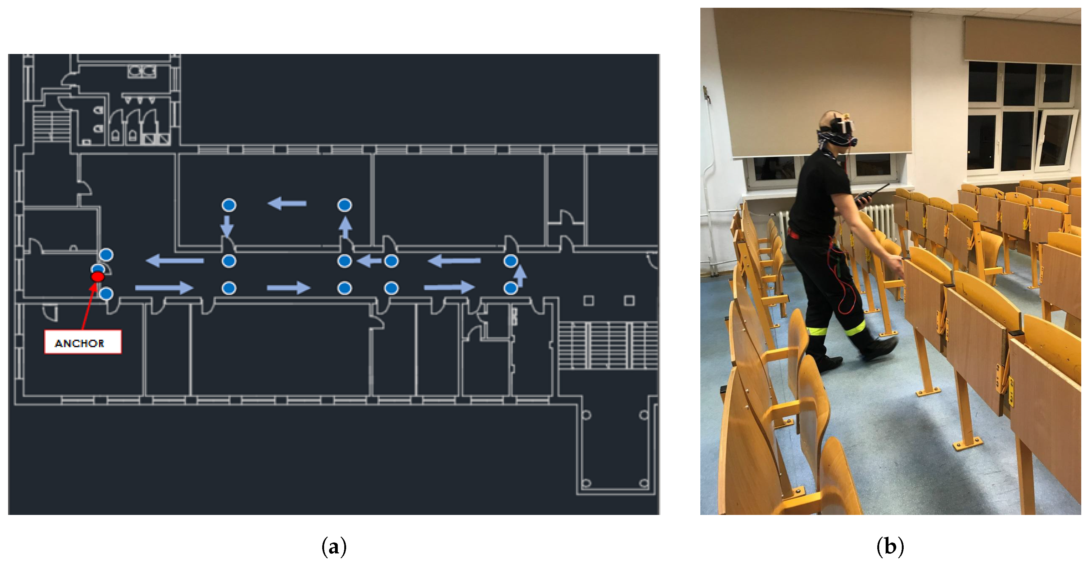
3.1. Instrumentation

Data acquisition hardware consisted of (a) an inertial sensor mounted on a shoe by a foot-strap (Figure 7a) and (b) a data acquisition unit (Figure 7b). Inertial data was gathered by a LSM6DS33—3-axial MEMS gyroscope and accelerometer in special casing, tightly mounted by a foot-strap on the shoe counter. Dynamic bandwidth was ± 8 g and ±2000 deg with 16-bit resolution for each axis. Raw data was sampled with 200 Hz and calibration of the sensors was performed beforehand with a linear error model with additional axis orthogonality correction. The Data Acquisition Unit (DAU) was constructed on Intel Edison Platform with a 32-bit Intel Atom processor on board. The INS algorithm was running on DAU and inter-step data was sent over a 868-MHz radio to the base station for storing and visualization.
An additional pair of Ultra Wide Band (UWB) radios was exploited to perform indoor ranging between a fixed point (an anchor node) and mobile agent. The anchor node depicts the ‘fall back’ place in firefighters’ tactics. Indoor Ranging (with wall obstacles) is problematic due to the phenomena called multipath effect [40], which means that little change in position can result in a very different path (which in the end results in a different time of flight). Analytical models suggest that a different path can result in different signal propagation, but a change of frequency can have a similar influence [40]. Therefore, UWB ranging means that measurements are taken consecutively at a number of different frequencies and the smallest ToF is taken into consideration.
The main component for performing UWB ranging was DW1000 from Decawave with third-party open source firmware. The module that we used was radino32 DW1000, additionally calibrated for bias. The operating frequency was 3993.6 MHz ± 665.6 MHz with 64 MHz Pulse Frequency.

3.2. Experimental Setup

The aim of a set of tests was to check the performance of the algorithm for map-matching. The measure of performance was the error in location. We carried out three different tests, each of which had two trials. At the beginning of the tests, we established a set of points with known coordinates. The goal of this set of coordinates was a quantitative comparison of the positions obtained from INS and the positions corrected by our map-matching algorithm.
The tests consist in moving an individual along the selected path, stopping at designated points, recording the position indicated by INS and moving to the next point. Then, the error was calculated as the relative distance of points indicated by INS and the real coordinates. The tests were repeated for locations with and without the collision avoidance velocity-based map matching algorithm. The consecutive tests were organized as follows:
Test I. The individual leaves the anchor at the starting point and starts to move along the designated path, through the middle of the corridor. The individual has to stop successively at five designated points with known coordinates. We record the position indicated by INS at each of these points. During the return to the starting point, the individual repeats the same activities as shown in Figure 8.
Test II. The individual leaves the anchor at the starting point and starts to move along the designated path, close to one wall of the corridor. The individual stops successively at five designated points with known coordinates. The position received from INS is recorded. During the return to the starting point, the individual has to move along the second, opposite wall of the corridor and repeats the same activities for the next five points. The main aim of this test was to check how our algorithm works in close proximity to the walls. Figure 9a,b illustrate Test II.
Test III. The aim of the last test was to check the navigation system with transition to other compartments. The path was selected to cross doors. The individual leaves the anchor at the starting point and starts to move along the designated path. The individual stops successively at five designated points with known coordinates. The position returned by INS is recorded. During the return to the starting point, the individual enters another compartment and stops at seven additional points with known coordinates, as shown in Figure 10a,b.
The test results were collected in a form, as is presented in Table 1.
The first column is the number of steps taken by an individual from the starting point. The second column contains the real coordinates of check points. The third column is the position indicated by INS. For each of the tests, we collected the data in such a table.

3.3. Experimental Results

In order to calculate the performance of our algorithm, we used Root Mean Squared Error metric. This allowed us to quantitatively verify the differences between real positions, values returned by INS, and values corrected by the algorithm. The Root Mean Squared Error is defined by the following formula:
R M S E = 1 N i = 1 N ( p i - p ^ i ) 2 ,
where N is the number of check-points with known coordinates, p i is the position at a given i-th check-point, p ^ i is the position indicated by INS or corrected by the map matching algorithm.
The results of the experiments are summarized in Table 2 and Table 3.

4. Discussion and Conclusions

The way in which firefighters move across buildings during search and rescue operations differs from the common way of movement. Therefore, instead of adopting one of the existing solutions, we decided to address the problem of navigation for firefighters from scratch. In the selection of the approach for error correction, we considered the limitations imposed by our INS as well as the specific environment in which firefighters operate.
Some of the possible solutions for our problem were rejected at the survey phase of related works, as is explained in Section 1. However, there still remains a set of applicable approaches. Nevertheless, we decided to develop another one, still having a chance to benefit from the existing ones as necessary.
We also decided not to repeat the respected test proposed by Microsoft for indoor navigation competition at International Conference on Information Processing in Sensor Networks (IPSN) (https://www.microsoft.com/en-us/research/event/microsoft-indoor-localization-competition-ipsn-2018). Since the competition test-bed is set up in large open spaces, we would not be able to test and implement our algorithm.
We did not, however, compare the other algorithms in our test cases, which is undoubtedly a shortcoming of our work. The quantitative comparison with other algorithms will form part of future work. Notwithstanding, a rough comparison of our results with IPSN competitors seems to confirm that there is still a place for our solution.
As is presented in the Results section, the algorithm reduces the error generated by our INS. In the best case, the error was reduced by almost 80%. However, in order for the algorithm to work efficiently, it needs proximity to the obstacle. This can be observed in Test I, where the agents moved along the middle of the corridor at some distance from the walls. In this case, the error reduction level was negligible. This naturally limits the scope of application of this algorithm—movement next to obstacles. This type of movement is typical for firefighters during search and rescue operations.
The algorithm also significantly reduces the maximum error. An additive error (the error that increases with distance travelled) is typical for INS. Generic INS achieves the maximum error close to seven meters, while our error correction technique keeps the maximum error close to two meters (when an agents moves along the walls).
In the future, we are going to gather more experimental data, in order to apply a genetic algorithm to define the ranges of angles accepted for position correction, door selection and transition to other compartments. The applied ORCA algorithm has a number of parameters to be set. Manipulation of these parameters may further improve the performance of our algorithm. At the current phase, these parameters were set experimentally in constraints to ensure the accuracy of the algorithm. The definition of these parameters is also in the scope of machine learning optimization, planned for future work.
Our primary goal within the project was to develop an indoor navigation system for firefighters. Therefore, we also tested the impact that our system may have on the safety of firefighters. We carried out fire-ground marked tests with the participation of firefighters. The goal of the tests was to compare the firefighters’ withdrawal times from the building with and without our navigation system. The tests showed that the withdrawal time of the group with the navigation system was almost half that of the group without the navigation system. The system significantly improves withdrawal times. However, this type of test does not explicitly show the impact of our algorithm for the withdrawal time. Hence, due to the scope of this article, the impact of the navigation system on firefighters’ tactics will not be broadly discussed.
Currently, the fire service is looking for a solution to the indoor navigation. Therefore, there is a great need to create such a system. Drawing paths in different colors for different firefighters and displaying these paths on the tablet, laptop or phone to the commander would enable firefighters to be located in buildings. In the case when one of the firefighters needs help, it provides the lost firefighter’s trail.
Future research should focus on testing the device for navigation in buildings with a more complex structure and in several-story buildings. In these tests we proposed slight changes to firefighters’ tactics, such as asking them to leave the anchors in characteristic places such as the entrances to apartments or staircases. Each time a firefighter passes near the anchor (during search and rescue), the position is corrected and error is reset. These assumptions allow us to perceive the building as a superposition of it smaller parts. This way our experiments on less complicated layouts make more sense.
In addition, the tests should be carried out under conditions of artificial smoke, so that firefighters can enter the building with air cameras. It is also necessary to conduct tests with improved devices, i.e., using two anchors spaced several meters apart, in order to improve the estimation of the pathway established by the inertial system.

Author Contributions

A.K. is responsible for the concept of the algorithm and its implementation. M.M. is responsible for the hardware and software related to the data acquisition and transmission. All of the authors are equally involved in the tests.

Funding

2017 Donald J. Burns Memorial Research Grant awarded by: Society of Fire Protection Engineers founded by: Bentley Systems.

Acknowledgments

The authors wish to express their most sincere gratitude towards the Society of Fire Protection Engineers, Bentley Systems and the jury that awarded the 2017 Chief Donald J. Burns Memorial Research Grant. The authors are also grateful to the company ConsultRisk sp. z o. o. for facilitating publication of this article. Additionally, the researchers thank Piotr Tofiło and Paula Smyczek for their support in preparing the tests of the system.

Conflicts of Interest

The authors declare no conflict of interest.

Abbreviations

The following abbreviations are used in this manuscript:
BLEBluetooth Low Energy
CADComputer Aided Design
CHAINCardinal Heading Aided Inertial Navigation
DAUData Acquisition Unit
DRDead Reckoning
GCSGlobal coordinate system
GNSSGlobal Navigation Satellite System
GPSGlobal Positioning System
INSInertial Navigation System
IPSNInternational Conference on Information Processing in Sensor Networks
LCSLocal coordinate system
MEMSMicro Electro Mechanical Sensor
RSSIReceived Signal Strength Indicator
MAPNMap-Aided Pedestrian/Individual Navigation
ORCAOptimal Reciprocal Collision Avoidance
RMSERoot Mean Squared Error
ToFTime-of-Flight
UWBUltra Wide Band

References

  1. Fahy, R.F.; LeBlanc, P.R.; Molis, J.L. Firefighter Fatalities in the United States—2016; Technical Report; National Fire Protection Association: Quincy, MA, USA, 2017. [Google Scholar]
  2. International Association of Fire Chiefs. Firefighter Near-Miss 2016 Annual Report; Technical Report; National Firefighter Near Miss Program: Fairfax, VA, USA, 2017. [Google Scholar]
  3. Woodman, O.J. An Introduction to Inertial Navigation; Technical Report; University of Cambridge, Computer Laboratory: Cambridge, UK, 2007. [Google Scholar]
  4. Foxlin, E. Pedestrian tracking with shoe-mounted inertial sensors. IEEE Comput. Graph. Appl. 2005, 25, 38–46. [Google Scholar] [CrossRef]
  5. Nilsson, J.O.; Skog, I.; Händel, P.; Hari, K. Foot-mounted INS for everybody-an open-source embedded implementation. In Proceedings of the 2012 IEEE/ION Position Location and Navigation Symposium (PLANS), Myrtle Beach, SC, USA, 23–26 April 2012; pp. 140–145. [Google Scholar]
  6. Angermann, M.; Robertson, P.; Kemptner, T.; Khider, M. A high precision reference data set for pedestrian navigation using foot-mounted inertial sensors. In Proceedings of the 2010 International Conference on Indoor Positioning and Indoor Navigation (IPIN), Zurich, Switzerland, 15–17 September 2010; pp. 1–6. [Google Scholar]
  7. Angermann, M.; Robertson, P. Footslam: Pedestrian simultaneous localization and mapping without exteroceptive sensors-hitchhiking on human perception and cognition. Proc. IEEE 2012, 100, 1840–1848. [Google Scholar] [CrossRef]
  8. Zhang, R.; Hoflinger, F.; Reindl, L. Inertial sensor based indoor localization and monitoring system for emergency responders. IEEE Sens. J. 2013, 13, 838–848. [Google Scholar] [CrossRef]
  9. Meina, M.; Krasuski, A.; Rykaczewski, K. Model fusion for inertial-based personal dead reckoning systems. In Proceedings of the Sensors Applications Symposium (SAS), Zadar, Croatia, 13–15 April 2015; pp. 1–6. [Google Scholar]
  10. Wang, Z.; Zhao, H.; Qiu, S.; Gao, Q. Stance-phase detection for ZUPT-aided foot-mounted pedestrian navigation system. IEEE/ASME Trans. Mechatron. 2015, 20, 3170–3181. [Google Scholar] [CrossRef]
  11. Nilsson, J.O.; Skog, I.; Händel, P. A note on the limitations of ZUPTs and the implications on sensor error modeling. In Proceedings of the 2012 International Conference on Indoor Positioning and Indoor Navigation (IPIN), Sydney, Australia, 13–15 November 2012. [Google Scholar]
  12. Liu, H.; Darabi, H.; Banerjee, P.; Liu, J. Survey of wireless indoor positioning techniques and systems. IEEE Trans. Syst. Man Cybern. Part C Appl. Rev. 2007, 37, 1067–1080. [Google Scholar] [CrossRef]
  13. Gu, Y.; Lo, A.; Niemegeers, I. A survey of indoor positioning systems for wireless personal networks. IEEE Commun. Surv. Tutor. 2009, 11, 13–32. [Google Scholar] [CrossRef] [Green Version]
  14. Cox, D.B. Integration of GPS with inertial navigation systems. Navigation 1978, 25, 236–245. [Google Scholar] [CrossRef]
  15. Link, J.A.B.; Smith, P.; Viol, N.; Wehrle, K. Footpath: Accurate map-based indoor navigation using smartphones. In Proceedings of the 2011 International Conference on Indoor Positioning and Indoor Navigation (IPIN), Guimaraes, Portugal, 21–23 September 2011; pp. 1–8. [Google Scholar]
  16. Klepal, M.; Beauregard, S. A novel backtracking particle filter for pattern matching indoor localization. In Proceedings of the First ACM International Workshop on Mobile Entity Localization and Tracking in GPS-Less Environments, San Francisco, CA, USA, 19 September 2008; pp. 79–83. [Google Scholar]
  17. Beauregard, S.; Klepal, M. Indoor PDR performance enhancement using minimal map information and particle filters. In Proceedings of the 2008 IEEE/ION Position, Location and Navigation Symposium, Monterey, CA, USA, 5–8 May 2008; pp. 141–147. [Google Scholar]
  18. Davidson, P.; Piché, R. A survey of selected indoor positioning methods for smartphones. IEEE Commun. Surv. Tutor. 2017, 19, 1347–1370. [Google Scholar] [CrossRef]
  19. Norman, J. Search and Rescue. In Fire Officer’s Handbook of Tactics; Fire Engineering Books: Tulsa, OK, USA, 2012. [Google Scholar]
  20. Honey, S.K.; Zavoli, W.B. A novel approach to automotive navigation and map display. IEEE Trans. Ind. Electron. 1985, 34, 40–43. [Google Scholar] [CrossRef]
  21. Quddus, M.A.; Ochieng, W.Y.; Noland, R.B. Current map-matching algorithms for transport applications: State-of-the art and future research directions. Transp. Res. Part C Emerg. Technol. 2007, 15, 312–328. [Google Scholar] [CrossRef] [Green Version]
  22. Bernstein, D.; Kornhauser, A. An Introduction to Map Matching for Personal Navigation Assistants; The National Academies of Sciences, Engineering, and Medicine: Washington, DC, USA, 1998. [Google Scholar]
  23. White, C.E.; Bernstein, D.; Kornhauser, A.L. Some map matching algorithms for personal navigation assistants. TTransp. Res. Part C Emerg. Technol. 2000, 8, 91–108. [Google Scholar] [CrossRef]
  24. Phuyal, B.P. Method and use of aggregated dead reckoning sensor and GPS data for map matching. In Proceedings of the ION GPS 2002: 15 th International Technical Meeting of the Satellite Division of The Institute of Navigation, Portland, OR, USA, 24–27 September 2002. [Google Scholar]
  25. Noureldin, A.; Karamat, T.B.; Eberts, M.D.; El-Shafie, A. Performance enhancement of MEMS-based INS/GPS integration for low-cost navigation applications. IEEE Trans. Veh. Technol. 2009, 58, 1077–1096. [Google Scholar] [CrossRef]
  26. Obradovic, D.; Lenz, H.; Schupfner, M. Fusion of map and sensor data in a modern car navigation system. J. VLSI Signal Process. Syst. Signal Image Video Technol. 2006, 45, 111–122. [Google Scholar] [CrossRef]
  27. Bao, S.D.; Meng, X.L.; Xiao, W.; Zhang, Z.Q. Fusion of inertial/magnetic sensor measurements and map information for pedestrian tracking. Sensors 2017, 17, 340. [Google Scholar] [CrossRef] [PubMed]
  28. Medina, D.A.; Schwaab, M.; Plaia, D.; Romanovas, M.; Traechtler, M.; Manoli, Y. A foot-mounted pedestrian localization system with map motion constraints. In Proceedings of the 12th IEEE Workshop on Positioning, Navigation and Communications (WPNC-15), Dresden, Germany, 11–12 March 2015. [Google Scholar]
  29. Ascher, C.; Kessler, C.; Wankerl, M.; Trommer, G. Dual IMU indoor navigation with particle filter based map-matching on a smartphone. In Proceedings of the 2010 International Conference on Indoor Positioning and Indoor Navigation (IPIN), Zurich, Switzerland, 15–17 September 2010; pp. 1–5. [Google Scholar]
  30. Leppäkoski, H.; Collin, J.; Takala, J. Pedestrian navigation based on inertial sensors, indoor map, and WLAN signals. J. Signal Process. Syst. 2013, 71, 287–296. [Google Scholar] [CrossRef]
  31. Pinchin, J.; Hide, C.; Moore, T. A particle filter approach to indoor navigation using a foot mounted inertial navigation system and heuristic heading information. In Proceedings of the 2012 International Conference on Indoor Positioning and Indoor Navigation (IPIN), Sydney, Australia, 13–15 November 2012; pp. 1–10. [Google Scholar]
  32. Gu, Y.; Song, Q.; Li, Y.; Ma, M. Foot-mounted pedestrian navigation based on particle filter with an adaptive weight updating strategy. J. Navig. 2015, 68, 23–38. [Google Scholar] [CrossRef]
  33. Zampella, F.; Ruiz, A.R.J.; Granja, F.S. Indoor positioning using efficient map matching, RSS measurements, and an improved motion model. IEEE Trans. Veh. Technol. 2015, 64, 1304–1317. [Google Scholar] [CrossRef]
  34. Franklin, S.; Graesser, A. Is it an Agent, or just a Program? A Taxonomy for Autonomous Agents. In Proceedings of the International Workshop on Agent Theories, , Architectures, and Languages, Budapest, Hungary, 12–13 August 1996; Springer: Berlin/Heidelberg, Germany, 1996; pp. 21–35. [Google Scholar]
  35. Madgwick, S. An efficient orientation filter for inertial and inertial/magnetic sensor arrays. Rep. x-io Univ. Bristol (UK) 2010, 25, 113–118. [Google Scholar]
  36. Park, S.K.; Suh, Y.S. A zero velocity detection algorithm using inertial sensors for pedestrian navigation systems. Sensors 2010, 10, 9163–9178. [Google Scholar] [CrossRef] [PubMed]
  37. Van Den Berg, J.; Guy, S.J.; Lin, M.; Manocha, D. Reciprocal n-body collision avoidance. In Robotics Research; Springer: Berlin/Heidelberg, Germany, 2011; pp. 3–19. [Google Scholar]
  38. Van den Berg, J.; Lin, M.; Manocha, D. Reciprocal velocity obstacles for real-time multi-agent navigation. In Proceedings of the IEEE International Conference on Robotics and Automation (ICRA 2008), Pasadena, CA, USA, 19–23 May 2008; pp. 1928–1935. [Google Scholar]
  39. Fiorini, P.; Shiller, Z. Motion planning in dynamic environments using velocity obstacles. Int. J. Robot. Res. 1998, 17, 760–772. [Google Scholar] [CrossRef]
  40. Foerster, J.R. The effects of multipath interference on the performance of UWB systems in an indoor wireless channel. In Proceedings of the 2001 IEEE VTS 53rd Vehicular Technology Conference (VTC 2001), Rhodes, Greece, 6–9 May 2001; Volume 2, pp. 1176–1180. [Google Scholar]
Figure 1. An example of how small error in rotation causes large error in location. The green line reflects the path received from INS. The purple lines define the walls. The proper path should start and finish at the same point. The estimated path ends with 12 m of error. The axes are defined in meters [m].
Applsci 08 01830 g001
Figure 2. The geometric interpretation of the velocity obstacle. (a) general idea; (b) limitation induced by τ constraints.
Applsci 08 01830 g002
Figure 3. Positions obtained from radio INS. Between each of the consecutive pairs of points, the velocity of the agent is calculated, stating the input for the ORCA algorithm. The green dots represent the points where the positions were measured. The purple lines represent building obstacles.
Applsci 08 01830 g003
Figure 4. A correction of the position—the agent collides with a wall. Ellipsis reflects the agent; purple lines define obstacles; the red arrow defines the velocity vector (as a subtraction of the position from INS and the agent’s current position); the gray arrow defines the collision avoidance velocity; the green line is the original path sent by the radio device. P ( x n , y n ) is the current position of the agent; P ( x n + 1 , y n + 1 ) is the next position obtained from INS; θ i is an angle for velocity rotation in order to avert collision; P ( x ´ n + 1 , y ´ n + 1 ) is the corrected position.
Applsci 08 01830 g004
Figure 5. Estimation of an agent’s path without any map matching algorithm. The axes are defined in meters [m].
Applsci 08 01830 g005
Figure 6. A path corrected by the map matching algorithm. The axes are defined in meters [m].
Applsci 08 01830 g006
Figure 7. Experimental INS system. (a) IMU mounted on a shoe with a foot-strap; (b) Data Acquisition Unit.
Applsci 08 01830 g007
Figure 8. Marked stop points (known coordinates) for the path in Test I.
Applsci 08 01830 g008
Figure 9. Test II. (a) Marked stop points for the path in Test II; (b) The movement along the wall during Test II.
Applsci 08 01830 g009
Figure 10. Test III. (a) Marked stop points for the path in Test III; (b) The movement across the furnished compartment during Test III.
Applsci 08 01830 g010
Table 1. Summary of data from an exemplary test. The position of the agent is relative to (0, 0) point, placed in the corner of the building.
Trial No. 1
StepReal Position [m]INS Position [m]Error [m]
0(5.12, 8.40)(5.11, 8.39)0.01
6(12.27, 8.40)(13.84, 8.14)1.59
12(20.90, 8.40)(20.53, 8.27)0.39
17(25.90, 8.40)(26.76, 8.04)0.93
21(31.60, 8.40)(30.77, 8.02)0.91
26(35.85, 8.40)(31.28, 7.19)4.73
30(31.60, 8.40)(27.24, 7.39)4.48
34(25.90, 8.40)(23.37, 7.63)2.64
40(20.90, 8.40)(15.66, 8.17)5.25
46(12.27, 8.40)(9.03, 8.48)3.24
51(5.12, 8.40)(4.32, 8.77)0.88
Table 2. Summary of Root Mean Squared Error for the system with and without map matching.
TestINSMap Matching Algorithm
Test I3.63 [m]3.01 [m]
Test II3.26 [m]0.73 [m]
Test III5.59 [m]1.15 [m]
Average4.16 [m]1.63 [m]
Table 3. Summary of maximal error at a check-point.
TestINSMap Matching Algorithm
Test I4.16 [m]3.71 [m]
Test II3.89 [m]2.12 [m]
Test III7.06 [m]2.15 [m]

