Abstract
The authors propose a novel unmanned underwater vehicle (UUV) based on a piezoelectric smart element, which facilitates piezoelectric energy harvesting as well as piezoelectric vibration reduction. In this report, the operating principle of the UUV is presented. Using Donnell’s theory, dynamic models of body structure are established, and the natural frequency sensitivity in addition to the vibration mode equations are deduced. Using MATLAB software, the vibration modes and their sensitivity to the change of investigated parameters are simulated. The results indicate that the natural frequencies are sensitive to the change of the middle surface radius and body length. It was also noted that the shear modes are more apparent for lower order vibrations, while the torsional moment modes are more significant for higher order vibrations. These results can be used both to optimize the dimensions of a UUV and to reduce its vibrations during operation.
1. Introduction
Unmanned underwater vehicles (UUVs) have been widely used in areas such as oceanographic surveys, underwater detection, undersea rescue, etc. [1,2,3]. Significant research progress has been made by researchers from all over the world in the investigation of UUVs. A Manta Test Vehicle (MTV) was built as the prototype of a new class of UUVs. This unit had complete nonlinear dynamics and control systems [4]. To support undersea mine hunting, a UUV named REDERMOR has been proposed to test different concepts of mine hunting. Meanwhile, the REDERMOR II is able to execute missions lasting several hours in autonomous mode [5]. In addition, a design methodology and a software module have been proposed for application to the design and manufacture of a stiffened pressure vessel, which can be mounted on a 6000 m class deep-sea unmanned underwater vehicle [6]. Cufí et al. [7] have presented the details for an automatic vision-based system for UUV station keeping. The station keeping system is based on a feature-based motion detection algorithm, which exploits standard correlation and explicit textural analysis to solve the correspondence problem. The following year, Guerrero-González et al. [8] proposed an intelligent navigation system for a UUV powered by renewable energy. This vehicle was designed for shadow water inspection during missions of a long duration. The proposed vehicle is a useful tool for monitoring large areas of the sea, and it has been used to monitor the Mar Menor lagoon. The same year, Du et al. [9] designed a bio-robotic unmanned underwater vehicle, and a new accurate model for calculating the fluid dynamics of flap-ping hydrofoil was used to simulate the motion of this vehicle. The results indicated that the bio-robotic UUV has excellent maneuverability at low velocity. The purpose of this vehicle is for navigation over long periods and large distances. To address the energy demands of long continuous operations, a rocking energy generation device based on wave energy is proposed [10].
Recently, significant advances in the development of UUV have been achieved. Zhang et al. [11] developed a method for a robust H-infinity control of a UUV based on the interpolation of the solution of the Riccati equation. The results showed that the controllers were feasible, effective, and robust for managing the control of the UUV. To address the navigation accuracy problems of multi-unmanned Underwater Vehicles (multi-UUVs) in the polar region, a polar cooperative navigation algorithm for multi-UUVs was proposed, which took communication delays into consideration. The results demonstrated that this proposed polar cooperative navigation algorithm can effectively navigate multi-UUVs in the polar region [12]. In addition, Martin et al. [13] gave a comparative experimental evaluation of one model-free proportional-derivative (PD) three degree-of-freedom (DOF) controller and two model-based three-DOF controllers, that were designed to facilitate low-speed, neutral buoyancy, and fully actuated underwater vehicles capable of performing trajectory tracking in the X, Y directions to heading DOFs.
The investigation on the UUV produced numerous valuable results. However, large amounts of wave energy are typically wasted during the operation of these vehicles. Hence, a novel piezoelectric-based UUV is proposed in this report that can facilitate piezoelectric energy harvesting as well as piezoelectric vibration reduction. Although the piezoelectric-based UUV has not been investigated as yet, the piezoelectric energy harvesting has been investigated and utilized by several researchers. Erturk et al. [14] developed a bimorph cantilever piezoelectric energy harvester. Experimental validation of the single-mode coupled voltage output and vibration response expressions is presented for a bimorph cantilever with a tip mass. Aghakhani et al. [15] proposed an analytical approach to derive the closed-form mechanical and electrical response expressions of multiple piezo-patch energy harvesters. Gozum et al. [16] developed a methodology for vibration analysis of laminated composite plates with surface-bonded piezo-patches. The Rayleigh-Ritz method was used to perform the modal analysis to obtain the frequency response functions. The results show that the developed analytical model can be utilized for accurate and efficient analysis, and the design of laminated composite plates with surface-bonded piezo-patches.
The vibration characteristics of the body structure of the proposed UUV significantly influenced its dynamic performance, which can result in a vehicle with a low stability. In this report, the working principles of the UUV are given. The dynamic model and the equations of the UUV are also established. In addition, the mode characteristics are analyzed, and the sensitivity characteristic of the frequency is investigated.
2. Operating Principle of the UUV
The structure of the proposed UUV is shown in Figure 1. It consists of a bow (2), stern (19), sonar (1), diving-surfacing system, control, and storage system, propelling system, visual detection system, piezoelectric energy collection system, and piezoelectric vibration reduction system. The diving-surfacing system is composed of a buoyancy cabin (3), water container (9), pushing device (10), fixed plate (11), and magnetic valve (8). The control and storage system is made up of an upper cover (25), battery cover (15), body structure (13), battery (21), energy storage (14), and controller (22). The propelling system includes a propeller (20) and a propulsion motor (16). In the case of the visual detection system, it contains a camera lens (6) and lens support (7). The piezoelectric energy collection system is composed of quadrate piezoelectric ceramics (4), a support ring (23), and annular piezoelectric ceramics (24). The piezoelectric vibration reduction system consists of piezoelectric ceramics integrated with a shunt circuit.
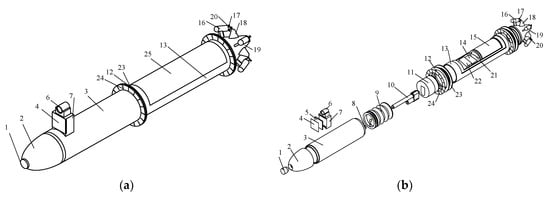
Figure 1.
Structure of the proposed unmanned underwater vehicle (UUV). (a) Solid model of the UUV; (b) exploded drawing of the UUV.
The operating principle of the proposed UUV is presented as follows: in the initial state, the buoyancy of the vehicle is greater than its weight. Therefore, the UUV floats on the surface of the water, and the pushing device is in its elongated state, while the magnetic valve is in a closed state.
When the circuit between the controller and the pushing device is connected, the pushing device retracts, whereas the magnetic valve is powered on under the command of the controller. At this moment, the water container starts to be filled with water, and the weight of the UUV exceeds its buoyancy. Hence, the UUV dives underwater. When the UUV achieves a preset depth, the controller sends a reverse voltage to the pushing device. This device again extends outward, thus pushing on the water-emptying container of the UUV to maintain underwater balance. Then, the controller regulates the magnetic valve and the pushing device in a stage of the outage, and the pushing device remains extended. Meanwhile, the propulsion motors are powered on and they all rotate with the same speed, which causes the UUV to move forward. When the rotation speed of the two motors on one side is larger than that of the motors on the other side, the UUV swerves based on the difference of velocity principle.
Upon completion of underwater operations, all of the propulsion motors of the UUV are powered off, the pushing device and magnetic valve are powered on, and the pushing device is extended to its initial length As such, the water container is emptied. At this time, the buoyancy of the UUV exceeds its gravity, and the UUV floats to the water surface.
In this report, piezoelectric energy harvesting, and piezoelectric vibration reduction are introduced for application to the UUV. Considering the working characteristics of this vehicle as well as increasing the vibration effectiveness of the piezoelectric ceramics, quadrate and annular piezoelectric ceramics are added to the piezoelectric energy collection system. Meanwhile, in the case of the annular piezoelectric ceramics, eighteen flabellate blades are joined onto the annular piezoelectric ceramic at the inner ring (see Figure 2a). Besides, the quadrate rubber mat and annular rubber mat are installed on the back of the quadrate and the annular piezoelectric ceramics to increase the energy collection effect. During the operation of the UUV, the wave motion of the water induces a reciprocating motion of the piezoelectric ceramics. This motion is transformed into electrical energy that is stored in reserve for later UUV use. In addition, to isolate the vehicle from the effect of the operation of the propeller, piezoelectric ceramics are utilized for vibration reduction based on an ultrathin piezoelectric fiber structure design. Furthermore, the resistance and inductance of the shunt circuit are set as adjustable values to adapt to different sea conditions (see Figure 2b). At the same time, during the operation of the UUV, the vibration energy of the propeller blade is absorbed by the resistance and inductance of the shunt circuit, which effectively achieves vibration reduction.
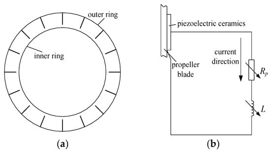
Figure 2.
Piezoelectric ceramics and shunt circuit. (a) Annular piezoelectric ceramics; (b) shunt circuit.
3. Dynamic Model and Equations
Figure 3 shows the dynamic model of the UUV body structure, where, u, v, and w represent the axial, tangential, and normal displacements of the middle surface, θ is the tangential angle, and l is the length of the body structure, while δ and Rm are the wall thickness and the middle surface radius, respectively.
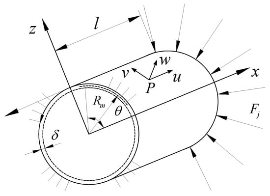
Figure 3.
Dynamic model of the UUV body structure.
It is assumed that the dynamic displacements are Δu, Δv, and Δw. Hence, from Donnell’s theory [17,18,19], the dynamic equations of the UUV’s body can be expressed by:
where, K and D are the shell stiffness and bending stiffness, respectively, , ; μ is the Poisson ratio; ρ is the material density of the body structure; ω is the natural frequency of the system; is the Laplace operator, ; k is a constant coefficient, .
Assuming the axial displacement and rotation angle at x = 0 and l are both zero, the boundary conditions are:
Thus, the dynamic displacement of the system can be written as:
where, , m and n are the axial and circumferential wave number, respectively.
Substituting Equation (3) into Equation (1), the following can be obtained:
where, , , , , , , .
The coefficients of Equation (4) have a nonzero solution, so the frequency equations can be written as:
Hence, the natural frequency of the system can be expressed by:
where, , , , .
For an arbitrary parameter κ, the sensitivity of the natural frequencies can be written as:
The frequency sensitivity with the middle surface radius Rm can be expressed by:
Meanwhile, the frequency sensitivities with wall thickness δ, body length l, and material density ρ are given as follows:
For a , letting coefficient C = 1, the following can be obtained:
From Equations (12) and (5), the vibration mode of the UUV body can be obtained.
Thus, the shear modes can be given as follows:
where, FSx and FSθ are thin film force modes along x and θ directions, while FSxθ is thin film shear force mode.
And the torsional moment modes can be expressed by:
where, Mx and Mθ are torsional moment modes along x and θ directions, while Mxθ is torsional moment mode.
4. Results and Discussion
4.1. Frequency Sensitivity Analysis
Table 1 shows the system parameters of the proposed UUV structure. Substituting the parameters into Equation (6), the natural frequencies of the UUV body structure can be determined (see Table 2). Similarly, substituting the parameters into Equations (8)–(11), the frequency sensitivity with parameter changes can be obtained, which are presented in Figure 4. Since the laws for a mode (m, n) with the three frequencies (ω1mn, ω2mn and ω3mn) are similar, only modes B(2, j) with the lowest frequency are selected to investigate the frequency sensitivity characteristic of the proposed UUV body. From Table 2 and Figure 4, it can be observed that:

Table 1.
System parameters.
Table 2.
Natural frequencies of unmanned underwater vehicle (UUV) body structure ω (rad/s).
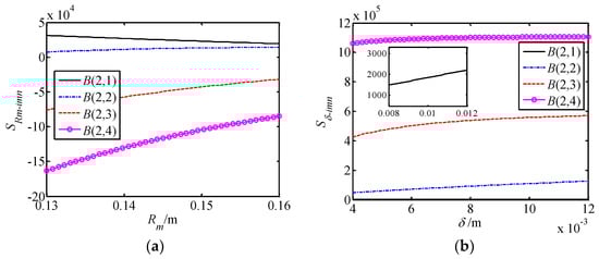
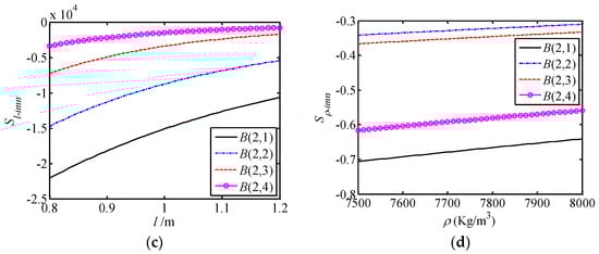
Figure 4.
Frequency sensitivity with parameter changes. (a) Rm changes; (b) δ changes; (c) l changes; (d) ρ changes.
(1) For a certain group of (m, n), there are three frequencies that exist in the system. When m and n are not all zero values, the three frequencies are different from each other. Since m and n increase, the three frequencies also increase. When the axial wave number m has a constant value, the first frequency ω1 decreases initially then increases as the circumferential wave number n increases. However, the second and the third frequencies (ω2 and ω3) increase with n for all values. In addition, when the circumferential wave number n has a constant value, the frequencies increase with the increase of the axial wave number m. But the increment of the first frequency ω1 is larger than that of the other conditions when n is quite small.
(2) The changing rate of the lower order frequencies is larger when the wave number changes. Hence, the lower order frequencies should be carefully examined and the lower order resonance should be avoided during the UUV operation.
(3) The middle surface radius Rm has a great influence on the frequency sensitivity. As Rm increases, the sensitivity of B(2,1) decreases, whereas the sensitivities of B(2,2), B(2,3) and B(2,4) increase. In addition, the changing rate of B(2,4) is largest, and has a maximum value of 52.9%. In addition, the circumferential wave number n influences the frequency sensitivity as well and the bigger the n, the larger the sensitivity.
(4) The change of frequency sensitivity with the parameters wall thickness δ and material density ρ are quite small. As δ and ρ increase, the sensitivity increases slightly.
(5) As the body length l increases, the frequency sensitivity also increases. With the increase of the circumferential wave number n, the changing rate of the frequency sensitivity is reduced, which is different from the sensitivity of Rm. Meanwhile, the effect of l on the frequency sensitivity is larger than that of δ and ρ.
In summary, the natural frequencies are sensitive to the change of the middle surface radius Rm and body length l, and these parameters should be carefully studied during the optimization of the structural dimensions of the UUV.
4.2. Vibration Modes Analysis
Figure 5 gives the normal displacement modes of the UUV body structure, since the normal direction vibration is the main vibration mode, so the normal displacement modes are given. Figure 6 and Figure 7 are the shear modes and torsional moment modes of the UUV body. In Figure 5, Figure 6 and Figure 7, only modes B(2,1) and B(4,2) with the lowest frequency are investigated. From these figures, the following is known:
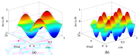
Figure 5.
Displacement modes of the UUV body structure with (a) B(2,1); (b) B(4,2).
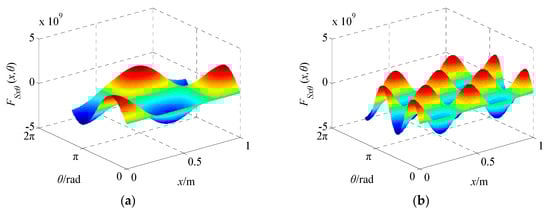
Figure 6.
Shear modes of the UUV body structure with (a) B(2,1); (b) B(4,2).
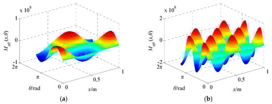
Figure 7.
Torsional moment modes of the UUV body structure with (a) B(2,1); (b) B(4,2).
(1) In the figures of the displacement modes, shear modes and torsional moment modes with a certain group of (m, n), m axial wave numbers are distributed on the outside surface of the cylinder along the axial direction, and n circumferential wave numbers are distributed on an arbitrary circular cross-section of the body structure.
(2) For the same order modes, the shear modes and the torsional moment modes have the same mode shape, and the difference between them is that the amplitude varies from one mode to another.
(3) As the mode order grows, the amplitude of the shear mode decreases, whereas the amplitude of the torsional moment modes increases. Hence, for lower order vibrations, the shear modes are the primary vibratory form, while for the higher order vibrations, the torsional moment modes are the main vibratory form.
In short, the shear modes and the torsional moment modes are influenced by the normal displacement modes of the UUV body structure. Hence, when the dynamic model is established, the mode characteristics of the UUV body structure are determined.
The influences of the UUV system parameters on the amplitude of its modes are also investigated. Based on this objective, two typical modes B(2,1) and B(4,2) are selected to be investigated for each parameter. The results obtained are presented in Figure 8, Figure 9 and Figure 10 and indicate the following:
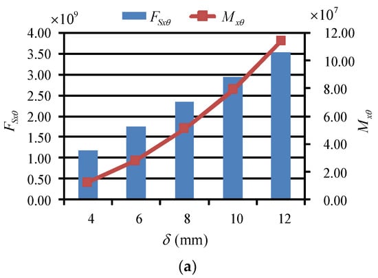
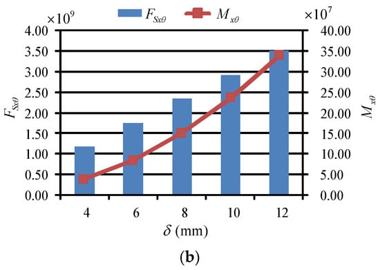
Figure 8.
Effect of wall thickness δ on modes amplitudes with (a) B(2,1); (b) B(4,2).
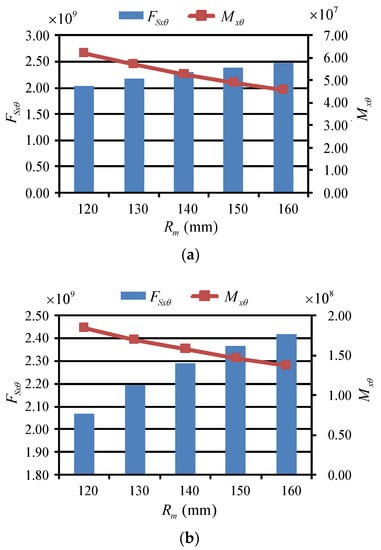
Figure 9.
Effect of middle surface radius Rm on modes amplitudes with (a) B(2,1); (b) B(4,2).
Figure 10.
Effect of body length l on modes amplitudes with (a) B(2,1); (b) B(4,2).
(1) As the wall thickness δ increases, the amplitude of the shear modes and the torsional moment modes increase. For the modes B(2,1) and B(4,2), the amplitudes of FSxθ and Mxθ at δ = 12 mm are three times and nine times larger, respectively, than the values at δ = 4 mm. Hence, the torsional moment modes response is more sensitive than the shear modes response with the change of parameter δ.
(2) With the increase of the middle surface radius Rm, the amplitude of the shear modes increases slightly, whereas the amplitude of the torsional moment modes decreases. Meanwhile, the amplitude of FSxθ increase by approximately 21 percent and 17 percent at modes B(2,1) and B(4,2), respectively, while the amplitude of Mxθ decrease by 26.1 percent and 25.7 percent, respectively. These results show that the torsional moment vibration modes are apparent when Rm is quite small, and that the shear vibration modes become increasingly significant as Rm becomes larger.
(3) Contrary to the law of δ changes, as the body length l increases, the amplitude of the shear modes and torsional moment modes decrease. The decrements of FSxθ at modes B(2,1) and B(4,2) are 43.8 percent and 40.7 percent, respectively. In addition, the decrements of Mxθ are 29.1 percent and 29.8 percent, respectively. The shear modes are more sensitive to the change of body length.
In summary, the relationships for FSxθ and Mxθ with changes in the investigated parameters for different mode orders are similar. In addition, the shear modes are more sensitive to a change of body length, while the torsional moment modes are more sensitive to an increase of the wall thickness. Therefore, these parameters should be carefully selected when designing and optimizing the structure of the proposed piezoelectric-based UUV.
5. Conclusions
In this report, a novel piezoelectric-based unmanned underwater vehicle (UUV) is proposed and its operating principle is presented. Using Donnell’s theory, the dynamic model and equations that describe the UUV’s body structure are established. Using these equations, the natural frequency sensitivity and vibration modes are deduced. The results indicate that:
(1) For a certain group of (m, n), there are three frequencies that exist in the system. The natural frequencies are sensitive to the change of the middle surface radius Rm and the body length l.
(2) The shear modes are more pronounced for the lower order vibrations, while the torsional moment modes are more significant for the higher order vibrations.
(3) The shear modes and the torsional moment modes are more sensitive to the change of the body length and wall thickness, respectively.
These results can be used to optimize the structure of the proposed UUV, and to reduce vibrations during operation.
Funding
This research was funded by Research Project of State Key Laboratory of Mechanical System and Vibration [grant number MSV201808], Natural Science Foundation of the Jiangsu Higher Education Institutions [grant number 18KJB460008] and Science and Technology Innovation Project of Jiangsu University of Science and Technology for Youth.
Conflicts of Interest
The authors declare no conflict of interest.
References
- Zhang, W.; Wei, S.; Teng, Y. Dynamic obstacle avoidance for unmanned underwater vehicles based on an improved velocity obstacle method. Sensors 2017, 17, 2742. [Google Scholar] [CrossRef] [PubMed]
- Alam, K.; Ray, T.; Anavatti, S. Design optimization of an unmanned underwater vehicle using low- and high-fidelity models. IEEE Trans. Syst. Man Cybern. Syst. 2017, 47, 2794–2808. [Google Scholar] [CrossRef]
- Xiang, X.; Yu, C.; Lapierre, L. Survey on fuzzy-logic-based guidance and control of marine surface vehicles and underwater vehicles. Int. J. Fuzzy Syst. 2018, 20, 572–586. [Google Scholar] [CrossRef]
- Menozzi, A.; Gagliardi, T.C.; Lyshevski, S.E. Dynamics and control of MTV: A multipurpose unmanned underwater vehicle. In Proceedings of the American Control Conference, Chicago, IL, USA, 28–30 June 2000; Volume 1, pp. 70–74. [Google Scholar]
- Toumelin, N.; Lemaire, J. New capabilities of the REDERMOR unmanned underwater vehicle. In Proceedings of the Oceans Conference Record (IEEE), Honolulu, HI, USA, 5–8 November 2001; Volume 2, pp. 1032–1035. [Google Scholar]
- Joung, T.-H.; Lee, J.-H.; Nho, I.-S. A study on the design and manufacturing of a deep-sea unmanned underwater vehicle based on structural reliability analysis. Ships Offshore Struct. 2009, 4, 19–29. [Google Scholar] [CrossRef]
- Cufí, X.; Garcia, R.; Ridao, P. An approach to vision-based station keeping for an unmanned underwater vehicle. In Proceedings of the IEEE International Conference on Intelligent Robots and Systems, Lausanne, Switzerland, 30 September–4 October 2002. [Google Scholar] [CrossRef]
- García-Córdova, F.; Guerrero-González, A. Intelligent navigation for a solar powered unmanned underwater vehicle. Int. J. Adv. Rob. Syst. 2013, 10, 185. [Google Scholar] [CrossRef]
- Du, X.; Song, B.; Pan, G. Dynamics and simulation of biorobotic UUV. Mechanika 2013, 19, 544–548. [Google Scholar]
- Deng, F.; Wang, K.; Ding, W. Rocking conversion system based on wave energy for unmanned underwater vehicle. Adv. Mater. Res. 2014, 953–954, 680–687. [Google Scholar] [CrossRef]
- Zhang, W.; Teng, Y.; Wei, S. The robust H-infinity control of UUV with riccati equation solution interpolation. Ocean Eng. 2018, 156, 252–262. [Google Scholar] [CrossRef]
- Yan, Z.; Wang, L.; Wang, T. Polar cooperative navigation algorithm for multi-unmanned underwater vehicles considering communication delays. Sensors 2018, 18, 1044. [Google Scholar] [CrossRef] [PubMed]
- Martin, S.C.; Whitcomb, L.L. Nonlinear model-based tracking control of underwater vehicles with three degree-of-freedom fully coupled dynamical plant models: theory and experimental evaluation. IEEE Trans. Control Syst. Technol. 2018, 26, 404–414. [Google Scholar] [CrossRef]
- Erturk, A.; Inman, D.J. An experimentally validated bimorph cantilever model for piezoelectric energy harvesting from base excitations. Smart Mater. Struct. 2009, 18, 025009. [Google Scholar] [CrossRef]
- Aghakhani, A.; Basdogan, I. Equivalent impedance electroelastic modeling of multiple piezo-patch energy harvesters on a thin plate with AC-DC conversion. IEEE/ASME Trans. Mechatron. 2017, 22, 1575–1584. [Google Scholar] [CrossRef]
- Gozum, M.M.; Aghakhani, A.; Serhat, G. Electroelastic modeling of thin-laminated composite plates with surface-bonded piezo-patches using Rayleigh–Ritz method. J. Intell. Mater. Syst. Struct. 2018, 29, 2192–2205. [Google Scholar] [CrossRef]
- Cao, Z. Vibration of Cylindrical Shell. Shell Vibration Theory, 1st ed.; China Railway Press: Beijing, China, 1989; pp. 290–317. [Google Scholar]
- Chung, S.W.; Hong, S.G.; Ju, G.S. Extension and reduction of Donnell-Vlasov shell theory to hybrid anisotropic materials. Compos. Struct. 2017, 172, 190–197. [Google Scholar] [CrossRef]
- Pentaras, D.; Elishakoff, I. Effective approximations for natural frequencies of double-walled carbon nanotubes based on Donnell shell theory. J. Nanotechnol. Eng. Med. 2011, 2, 021013. [Google Scholar] [CrossRef]
© 2018 by the author. Licensee MDPI, Basel, Switzerland. This article is an open access article distributed under the terms and conditions of the Creative Commons Attribution (CC BY) license (http://creativecommons.org/licenses/by/4.0/).