Article

Live Load Distribution Factors for Skew Stringer Bridges with High-Performance-Steel Girders under Truck Loads

1
Department of Landscape Architecture and Rural Systems Engineering, Seoul National University, Seoul 08826, Korea
2
School of Civil and Environmental Engineering, Georgia Institute of Technology, Atlanta, GA 30332, USA
3
Research Institute of Agriculture and Life Sciences, Seoul National University, Seoul 08826, Korea
4
Interdisciplinary Program in Landscape Architecture, Seoul National University, Seoul 08826, Korea
5
Interdisciplinary Program in Urban Design, Seoul National University, Seoul 08826, Korea
*
Author to whom correspondence should be addressed.
Appl. Sci. 2018, 8(10), 1717; https://doi.org/10.3390/app8101717
Submission received: 3 September 2018 / Revised: 17 September 2018 / Accepted: 20 September 2018 / Published: 21 September 2018
(This article belongs to the Section Mechanical Engineering)

Abstract

:
Because the methods used to compute the live load distribution for moment and shear force in modern highway bridges subjected to vehicle loading are generally constrained by their range of applicability, refined analysis methods are necessary when this range is exceeded or new materials are used. This study developed a simplified method to calculate the live load distribution factors for skewed composite slab-on-girder bridges with high-performance-steel (HPS) girders whose parameters exceed the range of applicability defined by the American Association of State Highway and Transportation Officials (AASHTO)’s Load and Resistance Factor Design (LRFD) specifications. Bridge databases containing information on actual bridges and prototype bridges constructed from three different types of steel and structural parameters that exceeded the range of applicability were developed and the bridge modeling verified using results reported for field tests of actual bridges. The resulting simplified equations for the live load distribution factors of shear force and bending moment were based on a rigorous statistical analysis of the data. The proposed equations provided comparable results to those obtained using finite element analysis, giving bridge engineers greater flexibility when designing bridges with structural parameters that are outside the range of applicability defined by AASHTO in terms of span length, skewness, and bridge width.

1. Introduction

Skewed composite high-performance-steel (HPS) I-girder bridges are an economical solution for modern highways subject to space constraints in congested urban areas, providing roadway alignments with low environmental impact and minimal pollution for new road construction projects. However, unlike in right-angle (non-skew) bridges, where the load transfer to the support is linear, skewed superstructures create high complexity in the force flow. In such structures, the load path tends to follow the shortest route to the supports at the obtuse corners of bridge spans, as shown in Figure 1. Skewness in the superstructure leads to concentration of the reaction forces and negative bending moments at the bridge’s obtuse corners, along with a small reaction and possibility of uplift reaction forces at its acute corners [1,2,3,4,5].
New types of the high-performance steel such as HPS 50 W (Fy = 345 MPa), HPS 70 W (Fy = 485 MPa) and HPS 100 W (Fy = 620 MPa), which became available commercially and globally in recent years, provide higher durability and strength, as well as boosted weldability. This can lead to considerable cost savings for big construction projects. For instance, Tennessee’s Department of Transportation reduced the cost of building a highway bridge by nearly 17% by using HPS [6]. HPS can also be highly beneficial when designing and constructing bridges with longer and shallower spans that exceed the range of applicability defined by the current specifications [1,7]. The critical issue limiting the wider use of HPS is our poor understanding of precisely how live loads are redistributed along a bridge’s transverse and longitudinal directions and in the girders of this type of bridge under realistic vehicle loads.
Prediction of load capacity of bridges under vehicle loads has been one of the most important issues in bridge engineering [8,9]. Therefore, the concept of Load Distribution Factors (LDFs) has been utilized by bridge engineers ever since the 1930s, in order to predict bridge responses under vehicle loads [10]. The simple “S-over” method proposed in the American Association of State Highway and Transportation Officials (AASHTO) standard [11] errs on the side of caution by predicting relatively conservative values for today’s bridges, especially those with skewed superstructures [12].
The more recent AASHTO LRFD specifications [13] accept the proposed LDF equations proposed in the National Copperative Highway Research Program (NCHRP) 12-26 project report [14] as an alternative to AASHTO’s standard method. These equations significantly boost the accuracy of LDFs, although the high complexity and defined limits of applicability often compel bridge designers to perform in-depth analyses. Multiple variations in the bridge parameters force engineers to make assumptions or refine their analysis when computing LDFs for skewed bridges or when they exceed the defined range of applicability. Meanwhile, the accuracy of the AASHTO LRFD equations used to calculate LDFs for composite bridges constructed using HPS girders remains somewhat controversial.
There have been many attempts to develop less complex, more accurate methods to compute LDFs for bridges [15,16,17]. Although Henry’s method [18] is solely a function of the number of girders and the width of bridge roadway, it is widely used because it calculates highly conservative values for skewed bridges’ LDFs [19]. The simplified models developed by Tarhini and Frederick [15] and Khaleel and Itani [20] yield accurate results only for single or two-lane loaded non-skewed bridges, while Menkulasi et al. [21] proposed a set of equations to quantify LDFs for short- to medium-span composite precast inverted T-beam bridges that produce reasonably accurate results over the specified range of applicability.
Suksawang and Nassif [22] applied the power function method to deduce simplified LDF equations for I-girder bridges that were a function of girder spacing alone. The validity of the equations provided in AASHTO LRFD [13] was experimentally verified for a specified range of applicability. Mohseni et al. [23] pointed out that the LDFs for shear and reaction at the piers and abutments of skewed bridges are different. It was, therefore, revealed that current AASHTO LRFD [13] LDF equations result in highly conservative values (by up to 25% for bridge with skew angle of 450) for the obtuse corners but un-conservative values (approximately 19%) for the acute corners of skewed superstructures. They, therefore, developed a set of correct factor expressions to obtain LDFs for reactions from the corresponding shear LDFs for multicell box-girder bridges.
Research into the effects of intermediate diaphragms (IDs) on live load patterns in skewed bridges has indicated that the spacing and arrangements of the IDs are decisive factors. Decks with IDs perpendicular to the longitudinal girders provide the best LDF s for skewed bridges [24,25].
The introduction of HPS materials has led to a growing number of long span bridge with narrow widths being constructed worldwide, all of which are outside the range of applicability of our current codes in term of both their materials and geometry. However, owing to a lack of simplified methods with which to compute the LDFs of these bridges, bridge engineers must perform complicated analyses when refining their designs. To address this problem, this study was undertaken to develop simplified LDFs equations or the bending moment and shear force acting on skewed composite bridges with HPS girders. Three-dimensional skewed bridges with various configurations of span length, skew angle, bridge width and girder spacing were investigated and the results of the analysis applied to develop a set of simplified LDF equations. Finally, the proposed equations were verified using a comparative study.

2. Finite Element Modeling and Verification
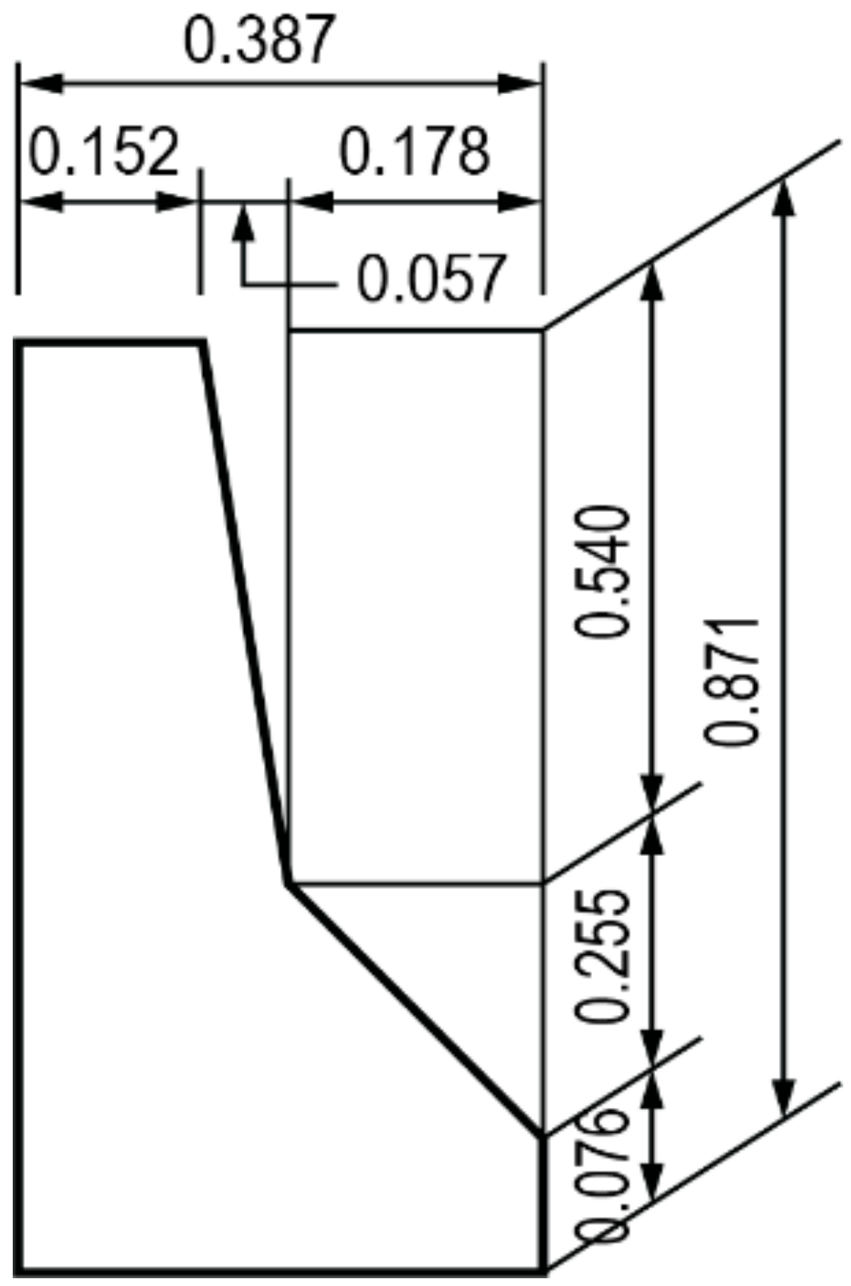
CSIbridge [26] software version 20 was used to carry out the analytical and parametric studies on skewed composite bridges. Data collected from field tests and experimental studies on actual bridges was used to verify the effectiveness of the proposed simulation methods for these structures.

2.1. Bridge Section

CSIbridge commercial software was applied to determine the responses of a skewed bridge subjected to vehicle loads. This software benefits from a vehicle load wizard that automatically draws an influence line along the path of a moving vehicle. This allows the maximum response and critical position of the vehicle to be determined conventionally.
In order to investigate the capacity of bridge components under vehicle loads, only the superstructure was modeled, neglecting the effect of the bending [14,27]. The three-dimensional (3D) finite element (FE) model of the superstructure consisted of a four-node shell element with six degrees of freedom (DOF) at each node. The effects of steel reinforcing and cracking of the RC slab were neglected. Longitudinal and transverse girders were modeled by means of 3D frame elements. The connection between the frame elements and the concrete slabs that they were supporting (shell elements) was provided automatically by the body constraint, vertical rigid links, defined in the CSIbridge software. Due to this assumption, no relative displacements and rotations were allowed between corresponding nodes [28].
The X-type intermediate diaphragms (bracing system) were modeled using four-node shell elements spaced at a distance at 7.5 m from each other. Double L-shaped angular profile brace members were described by means of frame elements hinged at the ends. The parapets were modeled as a single frame element with the connecting nodes of the parapets located at the centroid of the barrier section. The connection between the composite deck and the parapets utilized a series of rigid links to consider the contribution of parapet’s stiffness to the structural behavior [29].
The sizes of the mesh elements in the finite element modeling were determined based on the analysis efficiency, with a good expectation ratio for all elements. Simple (pin) bearings that could rotate but were fixed against translational moments in all directions were used to model the boundary conditions at the first abutment, while a roller bearing was applied to represent the end abutment and piers, where only vertical transitional movement was restricted [1,19]. A typical model of a skewed prototype bridge is shown in Figure 2.

2.2. Verification of Finite Element Models

2.2.1. Laboratory Tests at the Turner-Fairbank Highway Research Center

Phase one of the full-scale laboratory test was performed at the Turner–Fairbank Highway Research Center in McLean, Virginia (CSBRP project) [30]. This involved testing a horizontally curved composite slab-on-girder bridge subjected to construction and vehicle loads in order to verify the FE modeling. The bridge erected for this investigation was a 27.5 m simple-supported bridge with three steel concentric girders (G1, G2 and G3) spaced at intervals of 2.7 m. The ratio of curvature (k) to G2 was 0.45. A plan view and cross section of this bridge is shown in Figure 3. Tubular K-type cross frames with a diameter of 12.70 cm and a thickness of 0.635 cm were installed at different locations between the girders, as shown in Figure 1a. Full depth bearings were installed at multiple locations along the girders; the boundary conditions for the spherical bearings at the abutments are also shown in Figure 1. Load was applied to approximately the third point of each girder for the bending component test and this placed the load on G3 outside of the splices shown in Figure 3. Load application was accomplished by jacking the girders away from a series of loading frames that were tied with DYWIDAG bars to the laboratory strong floor. The frames consisted of channel pairs placed back-to-back and connected orthogonally to one another so that they formed the boxes shown in Figure 3d. Another back-to-back channel pair bisected each box and was used as a spreader beam to apply the loads. DYWIDAG bars, which were attached to the ends of the spreader beams, were selected because they provide high tensile strengths with minimal flexural stiffness. The mid-span girder deflections, rotations and strain distribution across the flanges and through the webs were recorded using potentiometers and tilt meters.
The entire bridge was modeled using CSIbridge software according to the previously described simulation technique in order to comprehensively verify the results of the FE modeling. Table 1 compares the girder vertical deflections and web rotations at the mid-span of the bridge obtained from the simulation and test when the bridge deforms elastically subject to its self-weight. The maximum discrepancy between the data recorded experimentally and the FE results is 8% for the vertical deflections at the mid-span and about 6% for the rotation of the girders.
In order to evaluate the capacity of the FE modeling to predict girder responses, Figure 4 and Figure 5 show the normal strain values at the flanges and web of girder G3 recorded during the laboratory tests and those obtained from the FE analysis. A maximum discrepancy of 6% was observed for both the web and flanges, confirming that the FE modeling technique can be used to analyze composite slab-on-girder bridges with adequate accuracy.

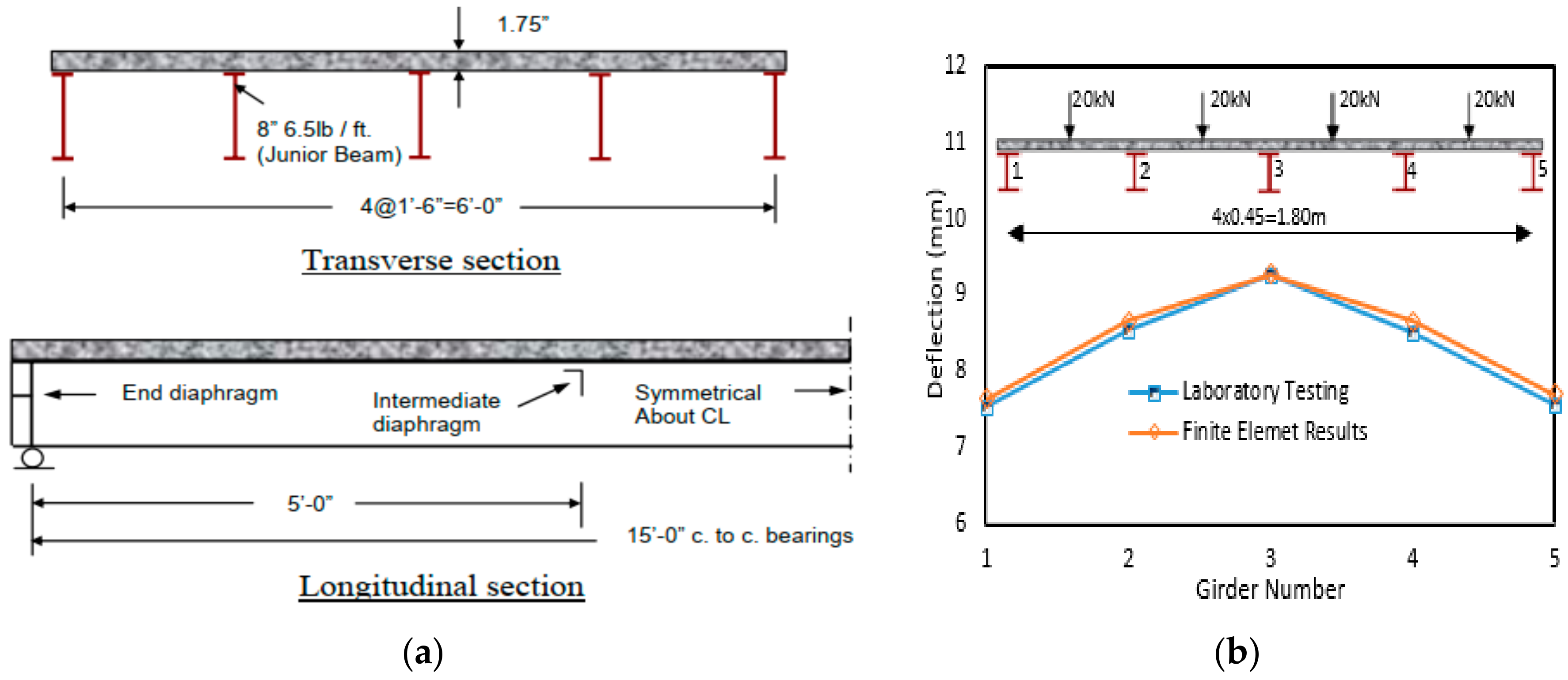
2.2.2. Laboratory Test of a Quarter Scale Model Bridge

Laboratory testing of a quarter-scale model for simple-span right bridge with a span of 18.2 m and a roadway width of 7.3 m was carried out by Newmark et al. [31]. The model bridge (referred to as C15) was a quarter-scale model with a span length of 4.5 m and deck width of 1.8 m supported by five I-girders at a spacing of 0.45 m. The cross section and longitudinal view of bridge are shown in Figure 5. The steel I-girders had a flange thickness of 4.80 mm, flange width of 58 mm, web thickness of 3.5 mm, and total height of 203 mm. Channels with dimensions of 25 mm × 9.5 mm × 0.30 mm and a spacing of 15.8 cm were installed as shear connectors and the intermediate diaphragms applied at the abutments and spaced at one-third intervals along each span consisted of 76 mm × 50 mm × 52 mm angles; these were welded to the webs of the beam about 13 mm below the top of the beam. Four 20 kN concentrated loads were applied at the mid-span symmetrically about the longitudinal axis of the bridge, as shown in Figure 5. As the figure shows, the laboratory and FE results compared fairly well, although the FE results were slightly higher than those obtained in the laboratory, varying by up to 1.5%, 4.6% and 3.4% for the external, intermediate and central girders, respectively. This discrepancy is likely because the experimental loads were not localized at an exact position but instead distributed over the entire steel supporting plate [32]. This suggests that the proposed FE technique accurately predicts the response of I-girder bridges to static loading.

3. Bridge Superstructure Database

Although High-Performance-Steel (HPS) girders need less steel compared with conventional steel girders, they are more likely to exceed the AAHTO LRFD [13] deflection limits. In order to take into account the AASHTO limits on performance and safety, it was therefore important to select a set of key parameters and build a matrix that covers a wide range of HPS bridges. The selected databases made it possible to design and optimize various combinations of parameters to capture a least weight approach. The prototype bridges were designed using CSIbridge software by neglecting the AASHTO criteria for deflection but satisfying the AASHTO LRFD criteria for the serviceability and strength of skewed bridges. Any HPS girders that were unable to satisfy the AASHTO live-load deflection criteria were redesigned.
Table 2 lists the databases and geometrical characteristics for the prototype bridges. Six span lengths (L) were utilized, at 30, 45, 60, 75, 90 and 105 m. The girder spacing (S) was taken to be 2.0, 2.5, 3, 3.5 or 4.0 m, depending on the number of girders (Ng). The skew angle (θ) at the abutment and piers increased across a range from 0° (non-skew bridges) to 60° at 15° intervals. Three deck widths were selected for this parameter study: 9.5, 13 and 15 m. The number of lane loads (NL) was taken to be 2 to 3 lanes for the bridges with total widths of 9 m and 13 m, and 2 to 4 lanes for bridges with a total width of 15 m, as shown in Table 2.
The American Iron and Steel Institute (AISI) standard parapet, shown in Figure 6, was modeled along both sides of the prototype bridges. The overhang slab length was taken to be half of the girder spacing and the thickness of the deck slab was 200 mm for all the bridges. Three types of High Performance-Steel, 50 W (Fy = 345 MPa), 70 W (Fy = 485 MPa), and 100 W (Fy = 620 MPa), were adopted for this study. Steel X-type diaphragms composed of L12 × 12 × 0.8 space at 5 m intervals along each span, and at the abutments and piers were modeled. The concrete deck had a modulus of elasticity of 28,000 MPa, a Poisson’s ratio of 0.2, and a density of 24 kN/m3.

4. Sensitivity Analysis

In order to investigate the influence of the various parameters on the structural responses of the skewed HPS girder bridges, a sensitivity study was performed. The main objective here was to categorize the variable exerting the most effect as this would play a vital role in determining a bridge’s LDFs. Once identified, these key parameters could then be used in the analytical analysis to develop a set of proposed LDF equations for skewed bridges. The parameters investigated were the span length, girder spacing, skew angle and number of lane loads.

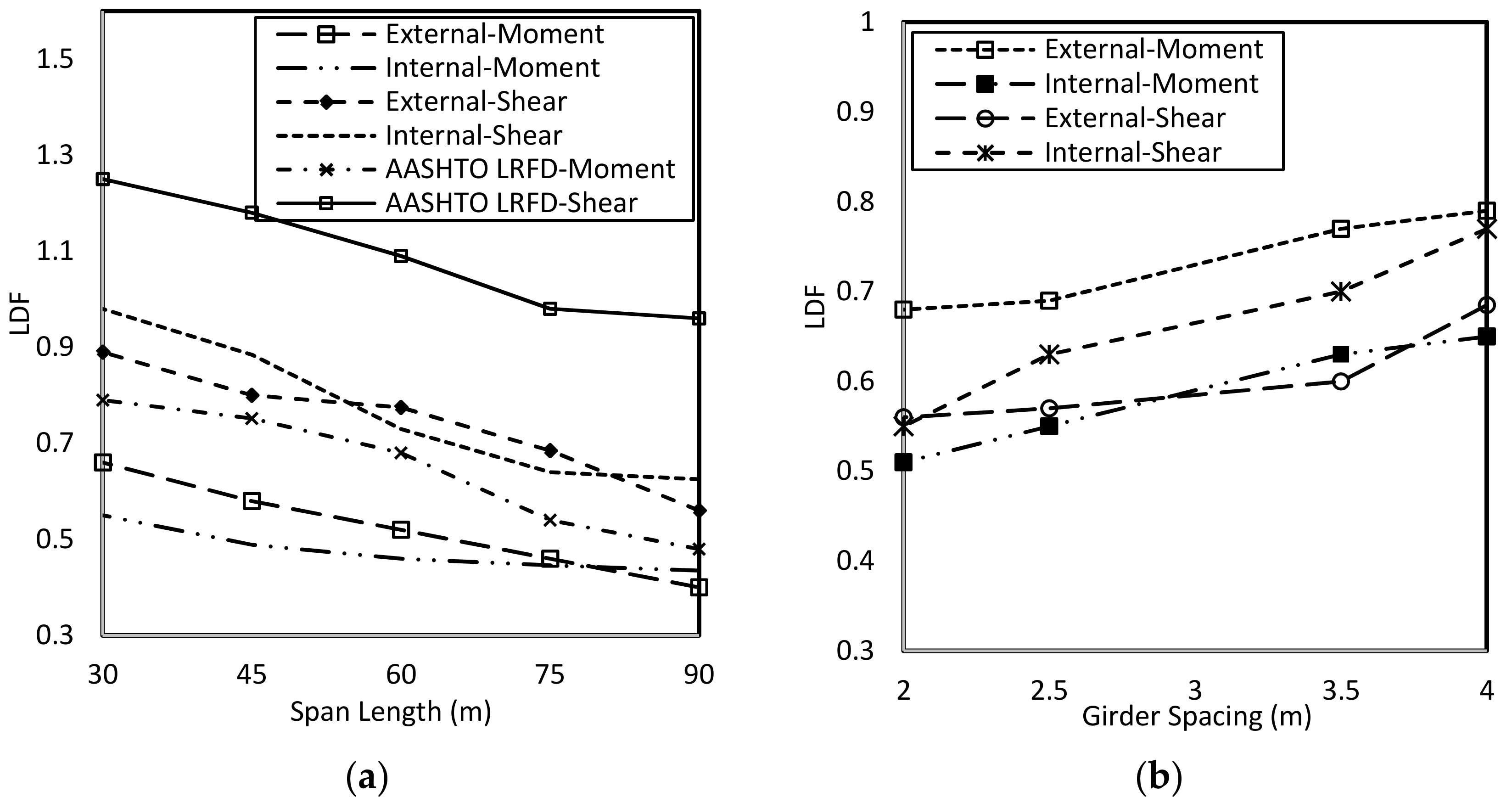
4.1. Effect of Span Length

Several researchers have investigated the importance of span length on the distribution of loads on the skewed superstructures [4]. For instance, several North American codes [13,14] have proposed LDFs to be functions of bridge span length.
Figure 7a shows the effect of span length on the LDFs for shear force and bending moment of a non-skewed bridge with a girder spacing of 2.5 m and a total width of 9.5 m. The results show that the LDFs decreased for both the external and internal bridge girders as the span length increased. The LDFs for the bending moment of the internal and external girders decreased by up to 27% and 46%, respectively, as the span length dropped from 30 m to 90 m. The same trend was visible for the LDFs for shear forces, which were reduced by up to 32% for both the internal and external girders as the span length increased. Although the current AASHTO LRFD [14] specifications have adopted Zokaie’s formulas for the LDFs of the shear and bending moment, the data presented in Figure 7 reveal that the AASHTO LRFD formulas produce highly conservative values for both the bending moment and shear force, which are up to 55% and 25% higher, respectively, than the results obtained by the FE analysis.

4.2. Effect of Girder Spacing

Bridges with a span length of 45 m and three lane loads, with girder spacings ranging from 2.0 to 4.0 m as described in Table 2, were investigated to verify whether girder spacing should be considered in the new proposed equations. Figure 7b indicates that the LDFs for the external and internal girders increased by approximately 14% and 22%, respectively, for the bending moment and by up to 18% and 28%, respectively, for the shear forces. These results follow the same trend as those reported by Zokaie [14] for ordinary bridges. Note that the girder spacing depends on the number of girders, as described earlier.

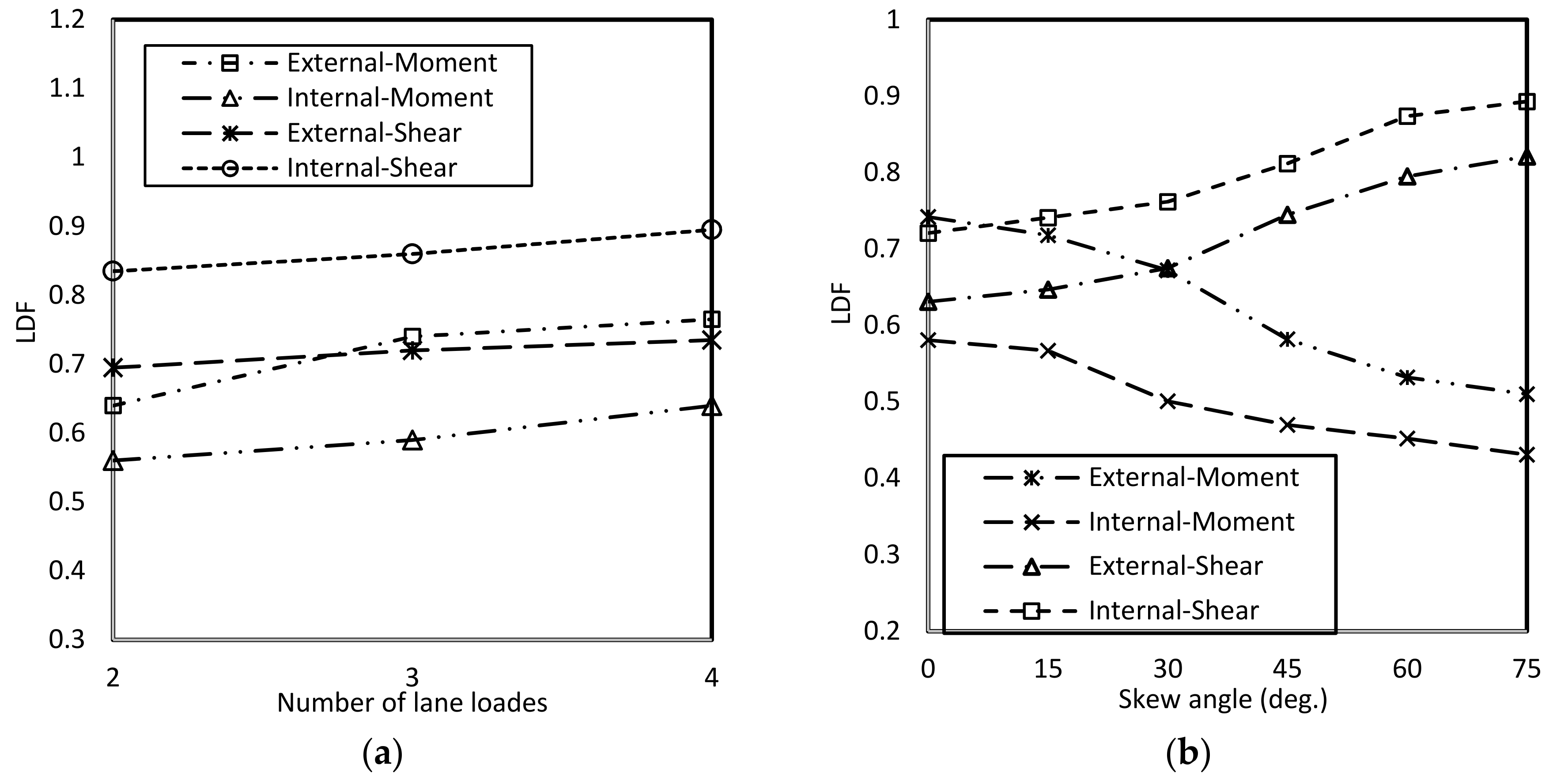
4.3. Effect of Number of Lane Loads

Next, the effect of the number of lanes within the same bridge width and span length was investigated. The results shown in Figure 8a reveal that increasing the number of lane-loads for a bridge with a total width of 13 and span length of 60 m increases the LDFs for shear force and bending moment by up to 15% and 7%, respectively. This suggests that the new LDF equations being developed should include the effect of the number of lane loads. A similar trend has been reported by researchers working on skewed composite slab-on-girder bridges constructed with conventional materials [14,25].

4.4. Effect of the Skew Angle

The results of the current parametric studies revealed that the skewness of the bridge is indeed a key parameter that has a significant effect on the LDFs for both the bending moment and shear force [33,34]. Figure 8b shows a plot of the effect of skewness on the shear and moment LDFs for the external and internal girders of a 45 m, four-lane loads, bridge with a girder spacing of 2.5 m. Here, the bending moment LDFs for the external and internal girders decreased by up to 45% and 34%, respectively, as the skew angle rose from 0° (non-skewed bridge) to 75°. Unlike the moment LDFs, the LDFs for the shear force rose by approximately 19% and 23%, respectively, for the external and internal girders, as shown in Figure 8b. This indicates that skewness must be considered in the proposed equations for the LDFs for bending moment and shear force.

5. Development of New Equations for the Live Load Distribution Factors

The sensitivity analysis revealed that the AASHTO LRFD [13] equations produce highly conservative values for the LDFs for bending moment and shear force for skewed bridge with HPS girders. The skewness at the abutments and piers of bridges also changes the load path, thus increasing the complexity of the bridge behavior. Live loads naturally seek the shortest path to the obtuse corner of the bridge’s superstructure, producing higher torsional moments and hence a greater reaction at obtuse corners of the bridge. This means that the LDFs for non-skewed bridges do not apply to skewed bridges and it is therefore necessary to develop new simplified equations for skewed bridges to ensure the safety and economy of these structures. To achieve this, statistical analyses based on least square regression [35] were performed to develop a new set of equations for skewed composite slab-on-girder bridges with HPS girders.
Based on the trend in the data revealed by the analyses presented above, the LDFs for the bending moment and shear force are assumed to take the following form;
L D F s = D F T × C F  
where CF is a correction factor whose expression must be determined via statistical analyses and DFT is the LDF equation deduced by Tarhini and Frederik [15] for a non-skewed I-girder bridge and is as follows;
D F T = 0.00013 L 2 0.021 L + 1.25 S ( S + 7 10 )  
Thus, the following equations were developed to describe the distribution factors for the bending moment (MDF) and shear force (SDF) for both external and internal girders.
- Live load distribution factors for bending moment
M D F e x = 5.09 D F T L 0.64 S 0.47 N L 0.21 e 0.08 Tan ( θ )  
M D F i n = 42.40 D F T L 0.74 S 0.074 N L 0.057 e 0.06 Tan ( θ )  
- Live load distribution factors for shear force
S D F e x = 12.61 D F T L 0.69 S 0.28 N L 0.25 e 0.125 Tan ( θ )  
S D F i n = 57.76 D F T L 0.80 S 0.16 N L 0.2028 e 0.06 Tan ( θ )  
where the subscripts, ex and in, denote the internal and external girders of the bridge, respectively.

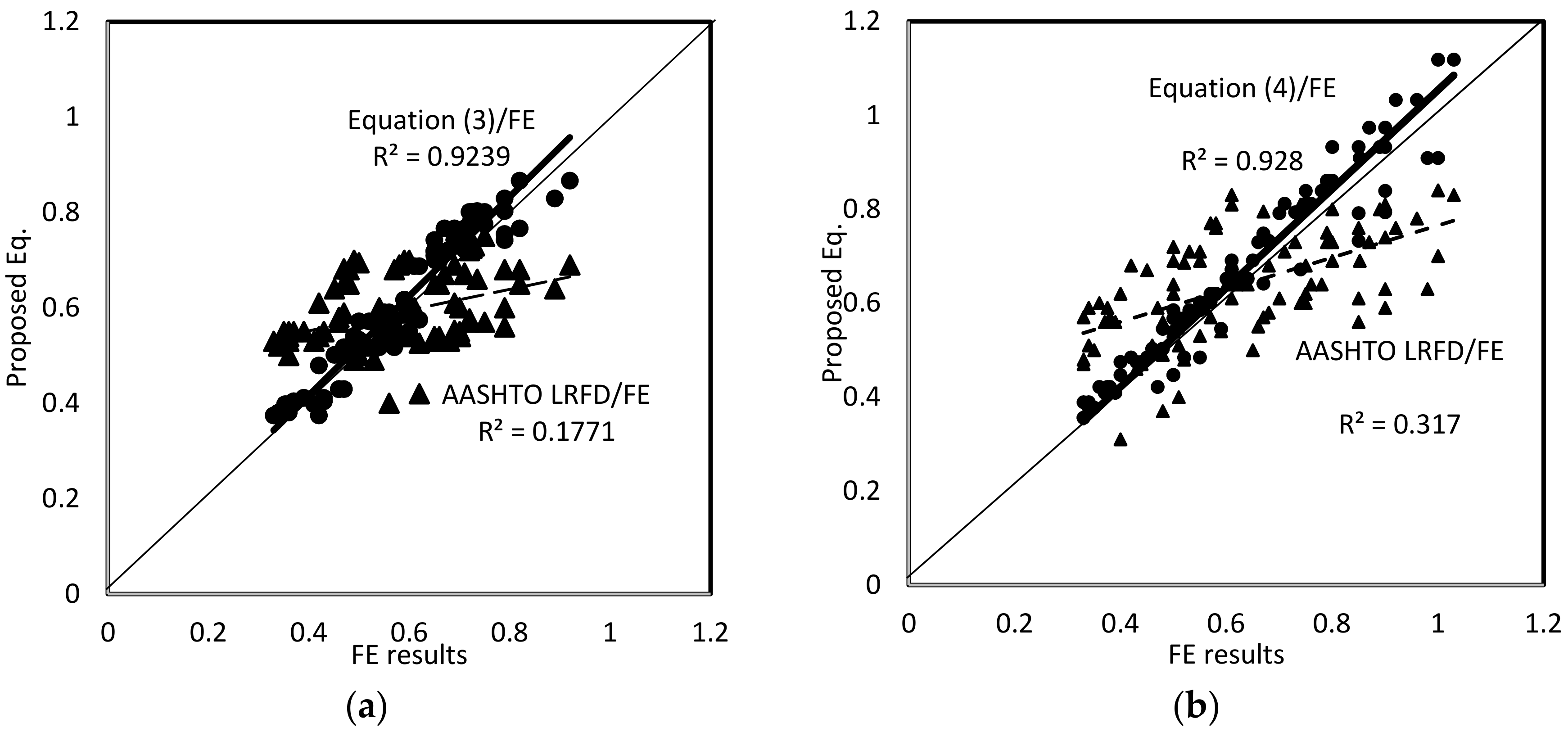
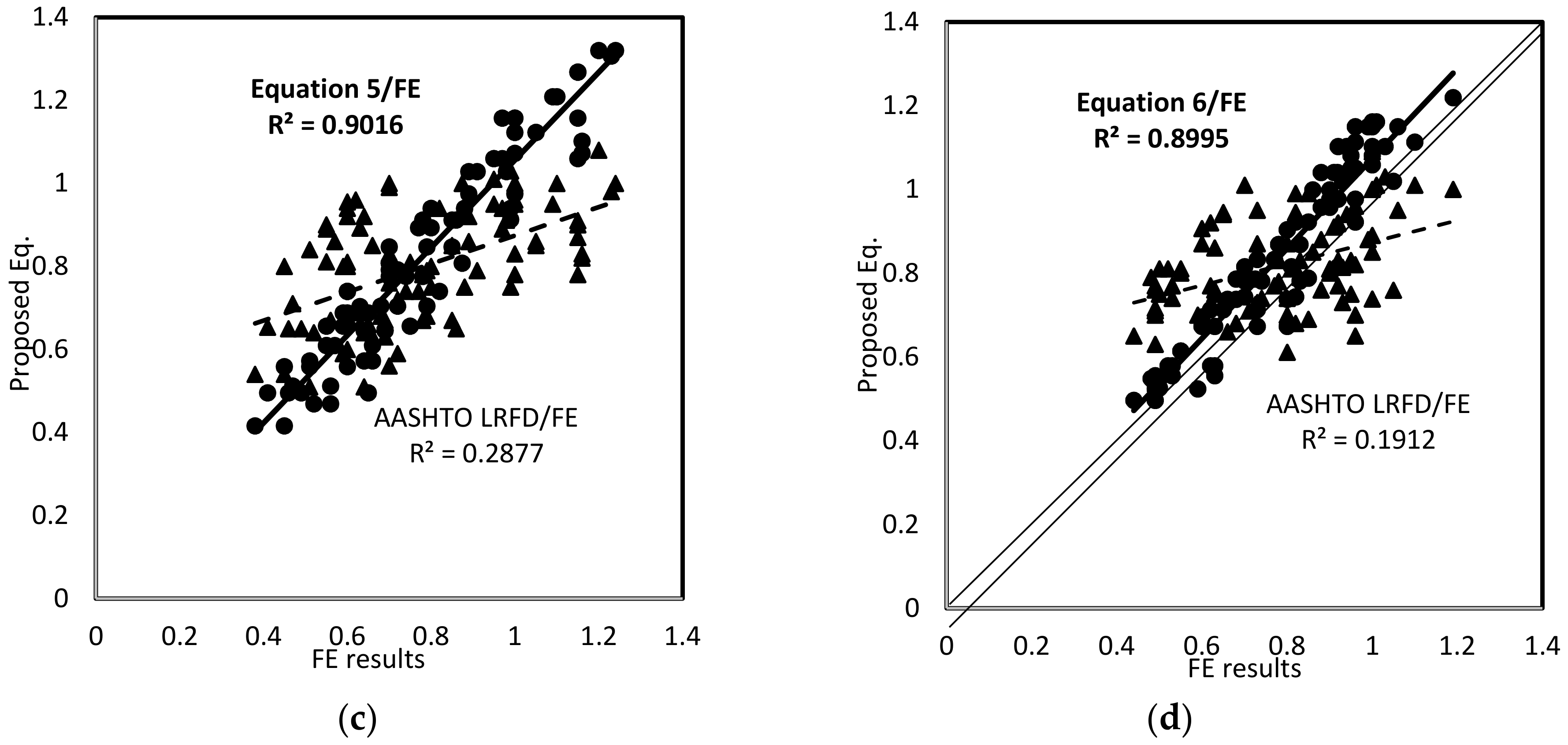
6. Verification of the Proposed Equations

The ratios of the LDFs from the proposed equations to the finite element values, shown in Figure 9, were used to verify the accuracy of the newly deduced LDF equations (Equations (3)–(6)) for bending moment and shear force. The coefficient of determination, R2, ranged from 0.899 to 0.930, indicating that the variation in the data falls with the acceptable range. In particular, the low value of R2 obtained for the ratio of AASHTO LRFD to FE results indicates that the current specification is unable to predict the LDFs for this type of bridge correctly. Table 3 shows the statistical results for the average (AVG.), standard division (SD.), and coefficient of variation (COV.) for the ratio of the results obtained using the proposed equations to those from the finite element analysis. The slightly-greater-than unity average obtained for the regression analysis reveals that the newly developed equations are indeed able to predict the LDFs for shear force and bending moment conservatively. The SDs listed in Table 3 range from 0.069 to 0.094 and the CVs are between 0.067 to 0.085, both of which confirm that the proposed equations can be used to determine LDFs for skewed bridges with HPS girders.

7. Conclusions and Recommendations

A detailed numerical investigation of the behavior of skew composite bridges with high-performance steel girders under truck loads was conducted for this study. The numerical approach applied included an extensive study of continuous bridges to determine the effect of various key parameters of bridges on the live load distribution factors for both shear and bending moment. Empirical expressions for the shear and bending moment distribution factors were derived that are suitable for use with current bridge design codes. The proposed expressions are a function of the skewness, girder spacing, number of lanes loaded, and span length of bridges. Based on the results obtained from the sensitivity investigation, the following conclusions can be drawn:
  • A good agreement in the structural responses was achieved between the 3-dimensional modeling of the prototype bridges and the results obtained experimentally, confirming that numerical models can reliably predict the responses of slab-on-girder bridges.
  • The discrepancy between the finite element results and those calculated using the codified AASHTO LRFD equations revealed that the current LRFD specifications are not suitable for predicting the live load distribution factors for both the bending moment and the shear force for skewed composite bridge with HPS girders. It was therefore necessary to develop a new set of LDF equations for both shear and moment.
  • Based on the results of the parametric study on prototype bridges, the span length, girder spacing, number of lane loaded, and skew angle were identified as the key parameters affecting the LDFs of skewed composite bridges. The LDFs for both shear force and bending moment decreased with increasing span length and number of lanes, and increased with increased girder spacing. Increasing the skew angle of the bridge superstructures increased the LDFs for shear force but decreased those for bending moment.
  • Based on the statistical analysis, conducted for this study, a set of simplified expressions were developed for the LDFs for both shear force and bending moment. The slightly greater than unity average and low standard deviation and coefficient of variation for each of the proposed expressions indicate high reliabilities for these proposed expressions in estimating the LDFs for shear force and bending moment of skewed composite bridge with HPS girders.
  • More studies can be carried to assess the dynamic interaction of these type of bridge and moving load due to traffic conditions. The simplified equations can be derived to determine dynamic impact factor of bridges with HPS steel.
  • Analytical and computational approaches to study the seismic response characteristics of bridges are the most economically feasible methods. It is particularly important to investigate the performance of skewed bridges with HPS steel due to vertical ground motions. The study, therefore, would provide comprehensive results through including all the parameters interacting for a wide range of skew angles.

Author Contributions

J.K. designed and coordinated the study. I.M. performed the theoretical and numerical study under the supervision of J.K. Y.K.C. reviewed the results of this study, and all authors have written and revised the text of this paper. All authors contributed to writing this paper.

Funding

This research was funded by Grants (18CTAP-C132633-02, 18CTAP-C144787-01) from the Ministry of Land, Infrastructure and Transport (MOLIT) of the Korean Agency for Infrastructure Technology Advancement (KAIA).

Acknowledgments

The work reported herein was supported by Grants (18CTAP-C132633-02, 18CTAP-C144787-01) funded by Ministry of Land, Infrastructure and Transport (MOLIT) of the Korean Agency for Infrastructure Technology Advancement (KAIA). This financial support is gratefully acknowledged.

Conflicts of Interest

The authors declare no conflicts of interest.

References

  1. Huo, X.S.; Zhang, Q. Effect of skewness on the distribution of live load reaction at piers of skewed continuous bridges. J. Bridge Eng. 2008, 13, 110–114. [Google Scholar] [CrossRef]
  2. Deng, Y.; Phares, B.; Lu, P. Lateral live-load distribution of dual-lane vehicles with nonstandard axle configurations. J. Bridge Eng. 2017, 22, 110–114. [Google Scholar] [CrossRef]
  3. Mohseni, I.; Khalim, A.R. Transverse load distribution of skew cast-in-place concrete multicell Box—Girder bridges subjected to traffic condition. Lat. Am. J. Solid Struct. 2013, 10, 247–262. [Google Scholar] [CrossRef]
  4. Nouri, G.H.; Ahmadi, Z. Influence of skew angle on continuous composite girder bridge. J. Bridge Eng. 2012, 17, 617–623. [Google Scholar] [CrossRef]
  5. Ebeido, T.; Kennedy, J.B. Girder moment in continuous skew composite bridge. J. Bridge Eng. 1996, 1, 37–45. [Google Scholar] [CrossRef]
  6. Hamby, G.; Clinton, G.; Nimis, R.; Lwin, M.M. High Performance Steel Designers’ Guide, 2nd ed.; U.S. Department of Transportation, FHWA: Washington, DC, USA, 2002.
  7. Mertz, D.R. Trends in design and construction of steel highway bridges in the United States. Prog. Struct. Eng. Mater. 2001, 3, 5–12. [Google Scholar] [CrossRef]
  8. Kim, S.H.; Heo, W.H.; You, D.W.; Choi, G.J. Vehicle loads for assessing the required load capacity considering the traffic environment. Appl. Sci. 2017, 7. [Google Scholar] [CrossRef]
  9. Kim, S.H.; Choi, G.J.; Heo, W.H.; You, D.W. Reliability evaluation of a PSC highway bridge based on resistance capacity degradation due to a corrosive environment. Appl. Sci. 2016, 6, 423. [Google Scholar] [CrossRef]
  10. Zokaie, T. AASHTO-LRFD live load distribution specifications. J. Bridge Eng. 2000, 10, 511–554. [Google Scholar] [CrossRef]
  11. American Association of State Highway and Transportation Officials (AASHTO). Standard Specifications for Design of Highway Bridges, 16th ed.; American Association of State Highway and Transportation Officials: Washington, DC, USA, 1996. [Google Scholar]
  12. Hue, X.S.; Wasserman, E.P.; Iqbal, R.A. Simplified method for calculating lateral distribution factors for live load shear. J. Bridge Eng. 2005, 5, 131–138. [Google Scholar] [CrossRef]
  13. American Association of State Highway and Transportation Officials (AASHTO). LRFD Bridge Design Specifications, 8th ed.; American Association of State Highway and Transportation Officials: Washington, DC, USA, 2017. [Google Scholar]
  14. Zokaie, T.; Imbsen, R.A. Distribution of Wheel Loads on Highway Bridges, National Cooperative Highway Research Program (Nchrp) 12-26 Project Report; Transportation Research Board, National Research Council: Washington, DC, USA, 1993. [Google Scholar]
  15. Tarhini, K.M.; Frederick, G.R. Wheel load distribution in I-girder highway bridges. J. Struct. Eng. 1992, 118, 1285–1294. [Google Scholar] [CrossRef]
  16. Mensah, S.A.; Durham, S. Live load distribution factors in two-girder bridge systems using precast trapezoidal U-girders. J. Bridge Eng. 2014, 19, 281–288. [Google Scholar] [CrossRef]
  17. Chung, W.; Phuvoravan, K.; Liu, J.; Sotelino, E. Applicability of the simplified load distribution factor equation to PSC girder bridges. KSCE J. Civ. Eng. 2005, 9, 313–319. [Google Scholar] [CrossRef]
  18. Huo, X.S.; Conner, S.O.; Iqbal, R. Re-Examination of the Simplified Method (Henry’s Method) of Distribution Factors for Live Load Moment and Shear; Project No. Tnspr-Res 1218; Tennessee Department of Transportation: Nashville, TN, USA, 2003. [Google Scholar]
  19. Mohseni, I.; Khalim, A.R. Development of the applicability of simplified Henry’s method for skewed multicell box-girder bridges under traffic loading conditions. J. Zhejiang Univ. Sci. A (Appl. Phys. Eng.) 2012, 13, 915–925. [Google Scholar] [CrossRef]
  20. Khaleel, M.A.; Itani, R.Y. Live-load moments for continuous skew bridges. J. Struct. Eng. 1990, 116, 2361–2373. [Google Scholar] [CrossRef]
  21. Menkulasi, F.; Wollmann, C.L.R.; Cousins, T. Live-load distribution factors for composite bridges with precast inverted T-beams. J. Perform. Constr. Facil. 2016, 30. [Google Scholar] [CrossRef]
  22. Suksawang, N.; Nassif, H.H. Development of live load distribution factor equation for girder bridges. TRB 2016, 2028, 9–18. [Google Scholar] [CrossRef]
  23. Mohseni, I.; Khalim, A.R.; Kang, J. Live load distribution factor at the piers of skewed continuous multicell box girder bridges subjected to moving loads. TRB 2015, 2522, 59–69. [Google Scholar] [CrossRef]
  24. Khaloo, A.R.; Mirzabozorg, H. Load distribution factors in simply supported skew bridges. J. Bridge Eng. 2003, 8, 241–244. [Google Scholar] [CrossRef]
  25. Mohseni, I.; Khalim, A.R.; Kang, J. Effect of intermediate diaphragm on lateral load distribution factor of multicell box-girder bridges. KSCE J. Civ. Eng. 2014, 18, 2128–2137. [Google Scholar] [CrossRef]
  26. Computers and Structures, Inc. CSIbridge, Version 20, Structural Software; Berkley: Hong Kong, China, 2018. [Google Scholar]
  27. Sennah, K.; Kennedy, J.B. Load distribution factors for composite multicell box girder bridges. J. Bridge Eng. 1999, 4, 71–78. [Google Scholar] [CrossRef]
  28. Bedon, C.; Dilena, M.; Morassi, A. Ambient vibration testing and structural identification of a cable-stayed bridge. Meccanica 2016, 51, 2777–2796. [Google Scholar] [CrossRef] [Green Version]
  29. Mohseni, I.; Ahn, Y.; Kang, J. Development of improved frequency expressions for composite horizontally curved bridges with high-performance steel girders. Arab. J. Sci. Eng. 2018. [CrossRef]
  30. Linzell, D.G. Studies of a Full-Scale Horizontally Curved Steel I-Girder Bridge System Under Self-Weight. Ph.D. Dissertation, Georgia Institute of Technology, Atlanta, GA, USA, 1999. [Google Scholar]
  31. Newmark, N.W.; Siess, C.P.; Penman, R.R. Studies of Slab and Beam Highway Bridges Part. I Tests of Simple-Span. Right I-Beam Bridges; Bulletin Series No. 363; The Engineering Experimental Station, The University of Illinois: Urbana, IL, USA, 1946. [Google Scholar]
  32. Wegmuller, A.W. Post elastic behavior of composite steel-concrete bridges. In Second International Conference on Finite Element Methods in Engineering; University of Adelaide: Adelaide, Australia, 1976. [Google Scholar]
  33. Zhang, Q. Development of Skew Correction Factors for Live Load Shear and Reaction Distribution in Highway Bridge Design. Ph.D. Dissertation, Tennessee Technological University, Cookeville, TN, USA, December 2008. [Google Scholar]
  34. Kashif, R.M. Load Distribution Factors for Skewed Composite Steel I-Girder Bridges. Ph.D. Dissertation, University of Windsor, Windsor, ON, Canada, December 2017. [Google Scholar]
  35. Erhan, S.; Dicleli, M. Live load distribution equations for integral bridge substructures. Eng. Struct. 2009, 1250–1264. [Google Scholar] [CrossRef]
Figure 1. Load paths in a skew bridge.
Applsci 08 01717 g001
Figure 2. Typical finite element (FE) model of a skewed composite I-girder bridge.
Applsci 08 01717 g002
Figure 3. Scaled bridge constructed for the laboratory tests at Turner–Fairbank Highway Research Center: (a) plan view; (b) cross-section; (c) location of instruments; (d) loading conditions.
Applsci 08 01717 g003
Figure 4. Strain at flanges and web of G3 from Test and FE analyses: (a) flange width; (b) web height.
Applsci 08 01717 g004
Figure 5. Deflection distribution at the girders along the mid-span cross section of the bridge: (a) cross section and longitudinal view; (b) deflection distribution factor.
Applsci 08 01717 g005
Figure 6. Standard American Iron and Steel Institute (AISI) parapet used for the bridge models (in meter).
Applsci 08 01717 g006
Figure 7. Effect of key parameters on bridge Load Distribution Factors (LDFs): (a) span length; (b) girder spacing.
Applsci 08 01717 g007
Figure 8. Effect of key parameters on bridge LDFs: (a) lane loads; (b) skew angle.
Applsci 08 01717 g008
Figure 9. Proposed LDF equations and American Association of State Highway and Transportation Officials (AASHTO) Load and Resistance Factor Design (LRFD)equations vs. Rigorous LDF. (a) bending moment of external girder; (b) bending moment of internal girder; (c) shear force of external girder; (d) shear force of internal girder.
Applsci 08 01717 g009aApplsci 08 01717 g009b
Table 1. Girder mid-span deflection under self-weight.
GirderVertical Defl. (cm)Web Rotat. (Degree)
FETestErrorFETestError
G10.470.516.20.180.195.5
G21.511.637.90.210.204.7
G32.832.694.90.330.316.10
Table 2. Characteristics of the prototype bridges.
SetL (m)HPS (w)L/DNLNgS (m)W (m)θ (Deg.)
1(30, 45, 60, 75, 90, 105)(50, 70, 100)202,33,4,5(2, 2.5, 3.0, 3.5, 4)9.5(0, 15, 30, 45, 60, 75)
2252,33,413
3302,33,413
4252,3,43,4,515
Table 3. Comparative Statistics of LDFs for prototype bridges.
LDFGirder TypeAVG.SD.COV.
MDFexExternal1.0650.0760.071
MDFinInternal1.0450.0690.067
CDFexExternal1.0720.0820.076
CDFinInternal1.0590.0940.085

