Linear Approximation Signal Detection Scheme in MIMO-OFDM Systems


Abstract
:1. Introduction
2. System Model
3. Conventional Detection Schemes
3.1. ZF
3.2. DFE
3.3. QRD-M
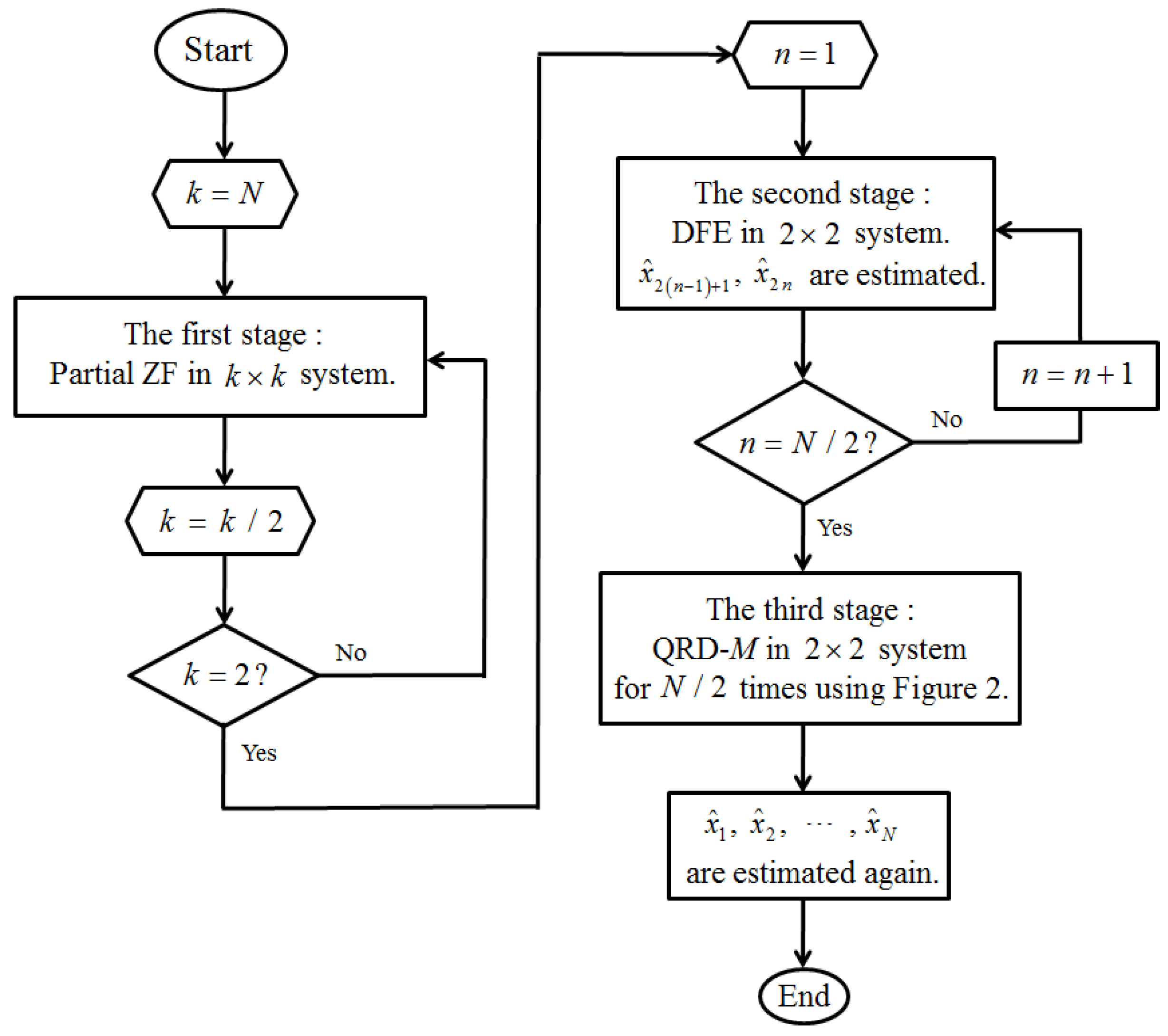
4. Proposed Detection Scheme
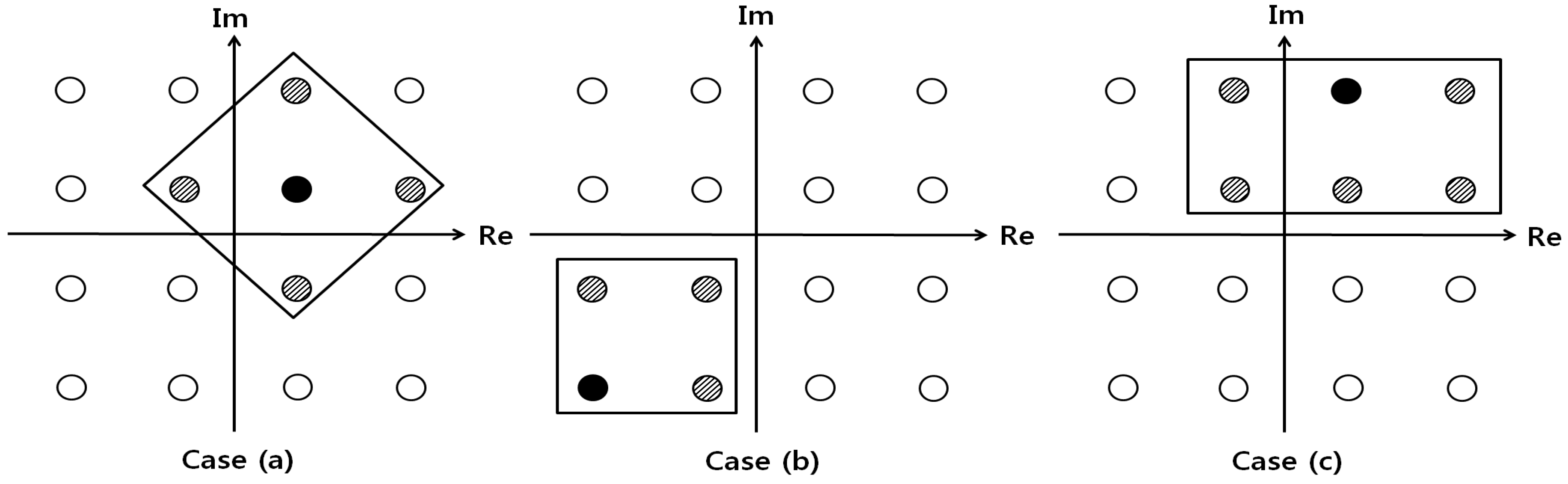
4.1. Partial ZF Stage
4.2. DFE Stage
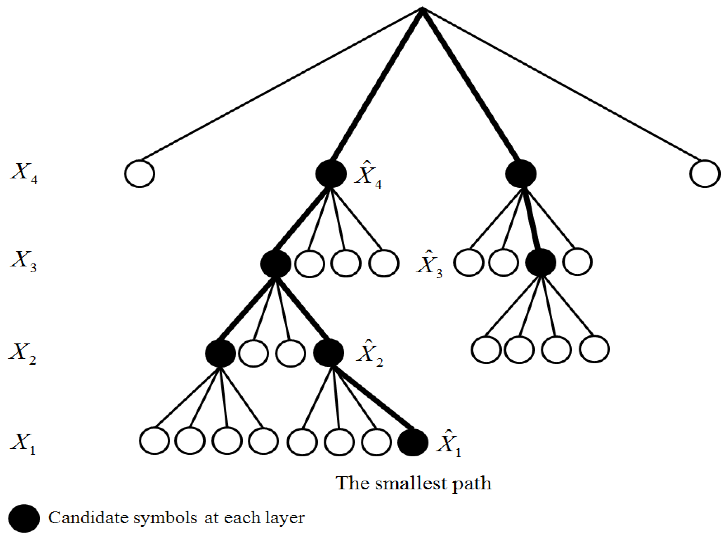
4.3. QRD-M Stage
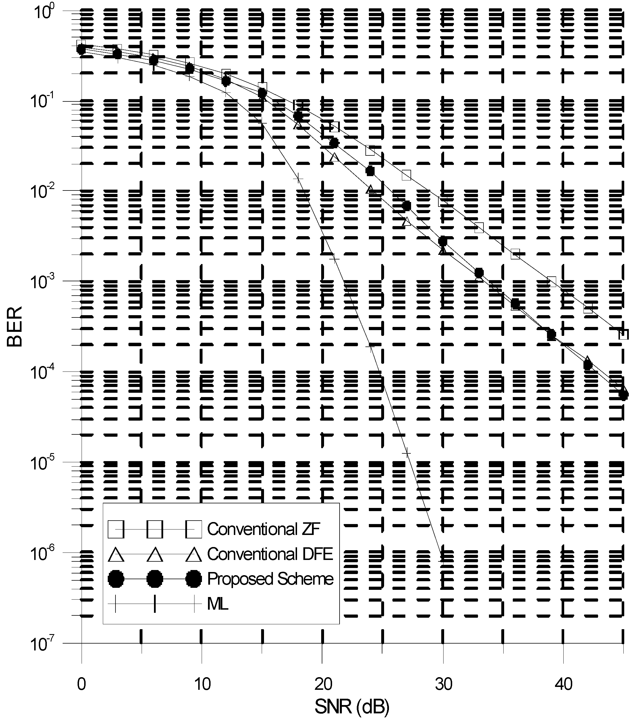
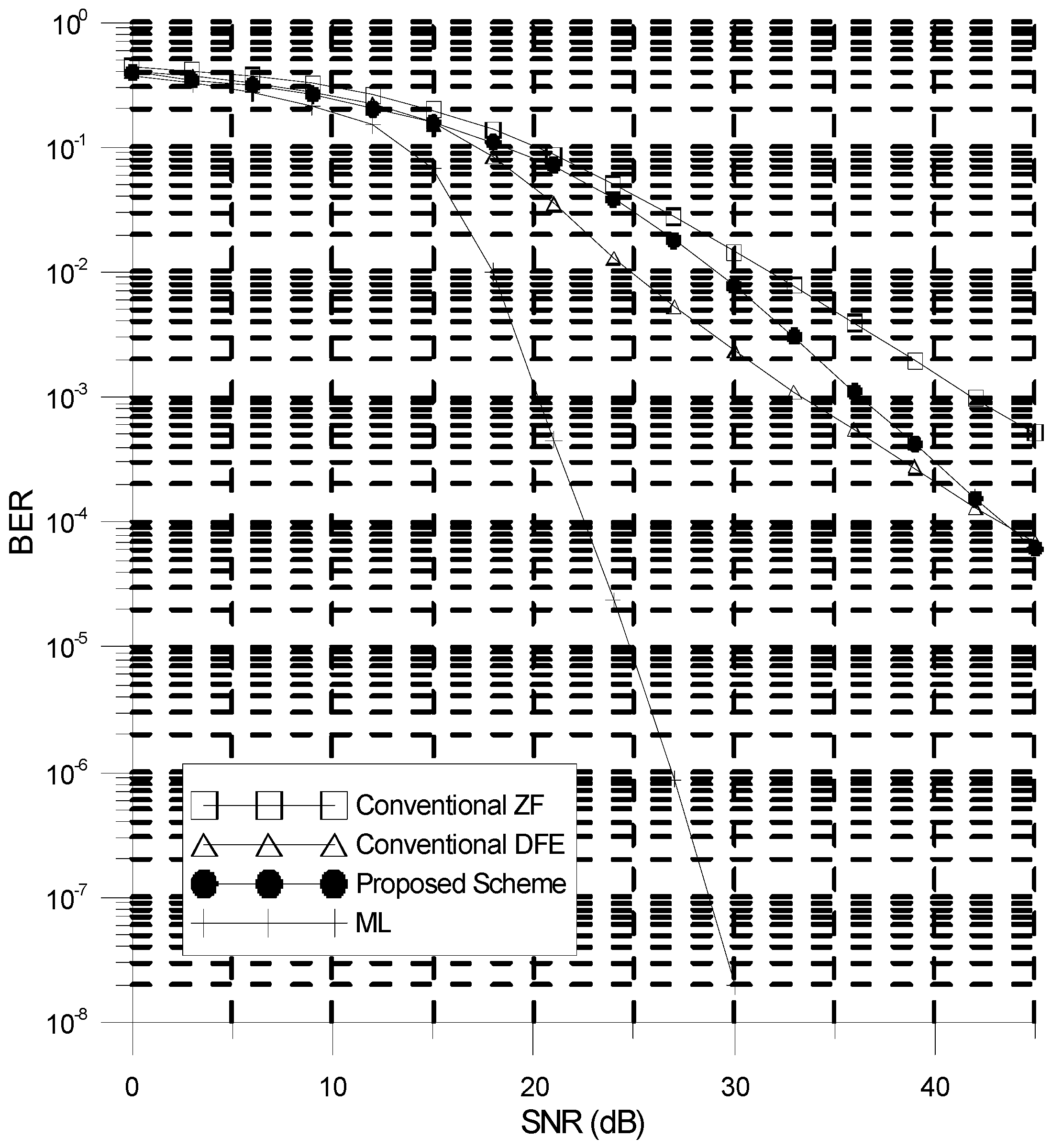
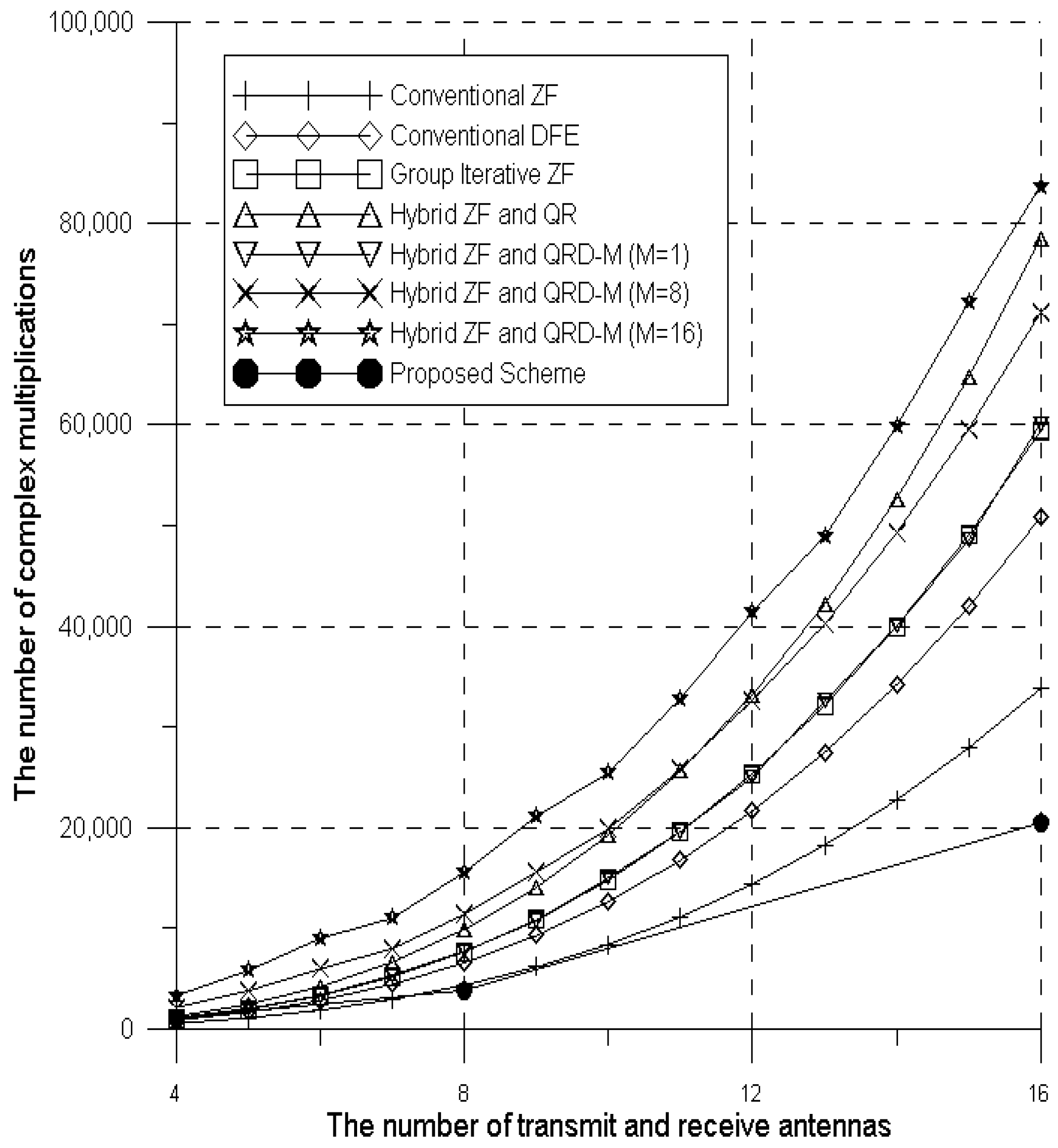
5. Simulation Results
6. Conclusions
Acknowledgments
Author Contributions
Conflicts of Interest
References
- Wolniansky, P.W.; Foschini, G.J.; Golden, G.D.; Valenzuela, R.A. V-BLAST: An Architecture for Realizing Very High Data Rates over the Rich-Scattering Wireless Channel. In Proceedings of the 1998 URSI International Symposium on Signals, Systems, and Electronics (ISSSE 98), Pisa, Italy, 29 September–2 October 1998; pp. 295–300. [Google Scholar] [CrossRef]
- Golden, G.D.; Foschini, C.J.; Valenzuela, R.A.; Wolniansky, P.W. Detection Algorithm and Initial Laboratory Results Using V-BLAST Space-Time Communication Architecture. Electron. Lett. 1999, 35, 14–16. [Google Scholar] [CrossRef]
- Baek, M.S.; Yeo, S.Y.; You, Y.H.; Song, H.K. Low Complexity ML Detection Technique for V-BLAST Systems with DFE Decoding. IEICE Trans. Commun. 2007, E90-B, 1261–1265. [Google Scholar] [CrossRef]
- You, W.; Yi, L.; Hu, W. Reduced Complexity Maximum-Likelihood Detection for MIMO-OFDM Systems. In Proceedings of the 8th International Conference on Wireless Communications, Networking and Mobile Computing (WiCOM), Shanghai, China, 21–23 September 2012; pp. 1–3. [Google Scholar] [CrossRef]
- Bohnke, R.; Wubben, D.; Kuhn, V.; Kammeyer, K.D. Reduced Complexity MMSE Detection for BLAST Architectures. In Proceedings of the 2003 IEEE Global Telecommunications Conference (GLOBECOM ‘03), San Francisco, CA, USA, 1–5 December 2003; Volume 4, pp. 2258–2262. [Google Scholar] [CrossRef]
- Wubben, D.; Bohnke, R.; Kuhn, V.; Kammeyer, K.D. MMSE Extension of V-BLAST Based on Sorted QR Decomposition. In Proceedings of the 2003 IEEE 58th Vehicular Technology Conference (VTC 2003-Fall), Orlando, FL, USA, 6–9 October 2003; Volume 1, pp. 508–512. [Google Scholar] [CrossRef]
- Wang, Z.; Zhang, S. Group Iterative Linear ZF Receiver for MIMO-OFDM Systems. In Proceedings of the 2010 Second International Conference on Networks Security Wireless Communications and Trusted Computing (NSWCTC), Wuhan, China, 24–25 April 2010; Volume 1, pp. 248–251. [Google Scholar] [CrossRef]
- Wang, Z.; Chen, F. A Hybrid ZF and QR Receiver for MIMO-OFDM Systems. In Proceedings of the 5th International Conference on Wireless Communications, Networking and Mobile Computing (WiCom’09), Beijing, China, 24–26 April 2009; pp. 1–4. [Google Scholar] [CrossRef]
- Ciuonzo, D.; Rossi, P.S.; Dey, S. Massive MIMO Channel-Aware Decision Fusion. IEEE Trans. Signal Process. 2015, 63, 604–619. [Google Scholar] [CrossRef]
- Ciuonzo, D.; Rossi, P.S.; Dey, S. Massive MIMO Meets Decision Fusion: Decode-and-Fuse vs. Decode-then-Fuse. In Proceedings of the 2014 IEEE 8th Sensor Array and Multichannel Signal Processing Workshop (SAM), A Coruña, Spain, 22–25 June 2014. [Google Scholar] [CrossRef]
- Wubben, D.; Bohnke, R.; Rinas, J.; Kuhn, V.; Kammeyer, K.D. Efficient Algorithm for Decoding Layered Space-Time Codes. Electron. Lett. 2001, 37, 1348–1350. [Google Scholar] [CrossRef]
- Peng, W.; Ma, S.; Ng, T.S.; Wang, J.Z. Adaptive QRD-M Detection with Variable Number of Surviving Paths for MIMO Systems. In Proceedings of the International Symposium on Communications and Information Technologies (ISCIT’07), Sydney, Australia, 17–19 October 2007; pp. 403–408. [Google Scholar] [CrossRef]
- Kim, B.S.; Choi, K.H. A Very Low Complexity QRD-M Algorithm Based on Limited Tree Search for MIMO Systems. In Proceedings of the IEEE Vehicular Technology Conference (VTC Spring 2008), Singapore, 11–14 May 2008; pp. 1246–1250. [Google Scholar] [CrossRef]
- Duan, X.; Ren, G.; Yang, L.; Yu, G. Low Complexity QRM-MLD Algorithm for MIMO Systems with 256 QAM Modulations. In Proceedings of the 12th IEEE International Conference on Communication Technology (ICCT), Nanjing, China, 11–14 November 2010; pp. 1052–1055. [Google Scholar] [CrossRef]
- Liu, S.; Qian, S. A Lower Complexity QRD-M Algorithm Based on VBLAST for MIMO-OFDM Systems. In Proceedings of the 2nd International Conference on Information Science and Engineering (ICISE), Hangzhou, China, 4–6 December 2010; pp. 1712–1715. [Google Scholar] [CrossRef]
- You, W.; Yi, L.; Hu, W. A Hybrid Dynamic QRDM and ZF Detection Algorithm for MIMO-OFDM Systems. In Proceedings of the 8th International Conference on Wireless Communications, Networking and Mobile Computing (WiCOM), Shanghai, China, 21–23 September 2012; pp. 1–4. [Google Scholar] [CrossRef]
- Lim, H.Y.; Jang, Y.S.; Li, T.; Yoon, D.W. Improved QRD-M Algorithm Based on Adaptive Threshold for MIMO Systems. In Proceedings of the 6th International Conference on Communication Systems and Networks (COMSNETS), Bangalore, India, 6–10 January 2014; pp. 1–4. [Google Scholar] [CrossRef]
- Baek, M.S.; Yun, J.; Hur, N.; Lim, H. Interference Cancellation and Signal Detection Technique Based on QRD-M Algorithm for FTN Signaling. Electron. Lett. 2017, 53, 409–411. [Google Scholar] [CrossRef]
- Guo, Z.; Nilsson, P. Algorithm and Implementation of the K-best Sphere Decoding for MIMO Detection. IEEE J. Sel. Areas Commun. 2006, 24, 491–503. [Google Scholar] [CrossRef]
- Romano, G.; Ciuonzo, D.; Rossi, P.S.; Palmieri, F. Low-Complexity Dominance-Based Sphere Decoder for MIMO Systems. Signal Process. 2013, 93, 2500–2509. [Google Scholar] [CrossRef]
- Papa, G.; Ciuonzo, D.; Romano, G.; Rossi, P.S. A Dominance-Based Soft-Input Soft-Output MIMO Detector with Near-Optimal Performance. IEEE Trans. Commun. 2014, 62, 4320–4335. [Google Scholar] [CrossRef]
- Sidiropoulos, N.D.; Luo, Z. A Semidefinite Relaxation Approach to MIMO Detection for High-Order QAM Constellations. IEEE Signal Process. Lett. 2006, 13, 525–528. [Google Scholar] [CrossRef]


| Detection Scheme | The Number of Complex Multiplications |
|---|---|
| Conventional ZF | |
| Conventional DFE | |
| Proposed scheme (Partial ZF stage) | |
| Proposed scheme (DFE stage) | 64N |
| Proposed scheme (QRD-M ZF stage) | |
| Group Iterative Linear ZF in [7] | |
| Hybrid ZF and QR Receiver in [8] | |
| Hybrid dynamic QRD-M and ZF in [16] | where denotes the integer number which is larger than or equal to . |
| Detection Scheme | Modulation: 16-QAM | , 16-QAM Modulation: 16-QAM | ||||
|---|---|---|---|---|---|---|
| Low complexity ML | ||||||
| 29 dB | 25.5 dB | 25 dB | 27 dB | 25 dB | 24.5 dB | |
| Proposed scheme | 33 dB | 36 dB | ||||
| Detection Scheme | Modulation: 16-QAM | Modulation: 16-QAM | ||||
|---|---|---|---|---|---|---|
| SMLD | ||||||
| 892 | 1284 | 1732 | 6708 | 8836 | 11268 | |
| Proposed scheme | 1089 | 3842 | ||||
© 2018 by the authors. Licensee MDPI, Basel, Switzerland. This article is an open access article distributed under the terms and conditions of the Creative Commons Attribution (CC BY) license (http://creativecommons.org/licenses/by/4.0/).
Share and Cite
Ro, J.-H.; Kim, J.-K.; You, Y.-H.; Song, H.-K. Linear Approximation Signal Detection Scheme in MIMO-OFDM Systems. Appl. Sci. 2018, 8, 49. https://doi.org/10.3390/app8010049
Ro J-H, Kim J-K, You Y-H, Song H-K. Linear Approximation Signal Detection Scheme in MIMO-OFDM Systems. Applied Sciences. 2018; 8(1):49. https://doi.org/10.3390/app8010049
Chicago/Turabian StyleRo, Jae-Hyun, Jong-Kwang Kim, Young-Hwan You, and Hyoung-Kyu Song. 2018. "Linear Approximation Signal Detection Scheme in MIMO-OFDM Systems" Applied Sciences 8, no. 1: 49. https://doi.org/10.3390/app8010049
APA StyleRo, J.-H., Kim, J.-K., You, Y.-H., & Song, H.-K. (2018). Linear Approximation Signal Detection Scheme in MIMO-OFDM Systems. Applied Sciences, 8(1), 49. https://doi.org/10.3390/app8010049