Article

The Influences of Assisting Gas Type and Process Parameters on the Fiber Laser Microprofiling of Thin CoCr Tubes for Vascular Stents

1
School of Mechanical Engineering, Nanjing University of Science and Technology, Nanjing 210094, China
2
Jiangsu Provincial Key Laboratory for Interventional Medical Devices, Huaiyin Institute of Technology, Huai’an 223001, China
*
Author to whom correspondence should be addressed.
Appl. Sci. 2017, 7(6), 608; https://doi.org/10.3390/app7060608
Submission received: 24 March 2017 / Revised: 4 June 2017 / Accepted: 7 June 2017 / Published: 12 June 2017
(This article belongs to the Section Optics and Lasers)

Abstract

:
Cobalt chromium (CoCr) alloy tubes have been widely used in manufacturing of vascular stents, due to their excellent bio-mechanical properties, especially their high strength. In recent years, fiber lasers have been used in the micro-machining of vascular stents, given their better cutting quality than neodymium-doped yttrium aluminum garnet (Nd:YAG) lasers. A comparison study of CoCr fiber laser cutting with oxygen and argon is presented, and the differences, such as surface topography, chemical composition, and kerfs geometry, between the oxygen cuts and argon cuts are studied. Three types of topographies are obtained for the oxygen cuts, and the underlying reason for the different topographies are discussed. The influences of key parameters including power, repetition rate, pulse width, and cutting speed on the cutting quality are analyzed. The present research can also provide an optimization guideline for the micro-profiling of CoCr vascular stents.

1. Introduction

Vascular stents are tiny mesh-like devices that are placed into an obstructed artery to open the lumen and allow smooth blood circulation [1]. Based on a stent’s expansion method, stents are classified into two categories: balloon-expanding and self-expanding. Materials such as 316L stainless steel, L605 CoCr alloy, and polymer are used for manufacturing balloon-expanding stents. NiTi alloy is used for manufacturing self-expanding stents, given its superior elastic and shape memory properties. In recent years, CoCr alloy has gained interest due to its excellent radial strength and, therefore, its ability to produce extra-thin struts with increased strength [2]. They are also MRI (Magnetic Resonance Imaging) compatible as well as radiopaque.
The design of stents is complex and, as they are very small, precise manufacturing processes are necessary. Because of the non-contact, precise, and localized energy inputs [3], 3D laser profiling has become the primary choice for stent cutting. Considerable research has been conducted on neodymium-doped yttrium aluminum garnet (Nd:YAG) laser cutting of stents. Kathuria et al. [4] described the precision manufacturing of stainless steel stents using a Nd:YAG laser, and a noticeable heat-affected zone (HAZ) was detected in the cross-sections. To minimize the HAZ size, optimized process parameters (a high repetition rate and short pulse width) were suggested. Pfeifer et al. [5] investigated the Nd:YAG laser cutting of NiTi alloys and studied the influences of process parameters on cutting quality. The detected HAZ size ranged from 6 to 30 μm. Embrittlement in the HAZ can lead to microcracks and shorten a stent’s fatigue life, as described by Miller et al. [6]. Sudheer et al. [7] reported the Nd:YAG laser cutting of CoCr stents, and a strut width dimension error of ±15 μm was detected. Raval et al. [8] cut 316LVM stents using Nd:YAG lasers, and a strut dimension of 150 ± 15 μm was achieved. The dimension error of struts can influence the stents’ mechanical properties.
In recent years, fiber lasers have been widely used in micromachining for higher beam quality, reliability, and process efficiency. Comparative studies on Nd:YAG lasers and fiber lasers have been conducted. Fiber lasers have been proved to have better cutting quality than Nd:YAG lasers in terms of kerf size, roughness, and HAZ. Kleine et al. [9] found that using fiber lasers can result in smoother cutting surfaces. Meng et al. [10] demonstrated that cutting quality (HAZ and average roughness) was better with a fiber laser compared to an Nd:YAG laser. To further improve the quality of fiber laser cutting, Muhammad et al. [11] introduced a water flow through the inner wall of the tube, which resulted in a narrower kerf width, lower surface roughness, less dross, as well as a smaller HAZ compared to dry cutting.
Fiber lasers have also been used in manufacturing biodegradable stents. In the work of Demir et al. [12,13], microcutting biodegradable stents from AZ31 magnesium alloy with a Q-switched fiber laser in the ns-pulse regime, as well as inert and reactive gas cutting conditions, were compared. The study found that the laser microcutting of AZ31 Mg alloy required inert gas conditions, as opposed to reactive cutting with O2.
Defects, such as dross formation and HAZ, are always inevitable, because the mechanisms of long-pulse lasers include thermal heating, melting, and evaporating of base materials, as explained by Fu [14]. Sweeney et al. [15] presented a framework for an experimental test of crystal plasticity micro-mechanics for the high-cycle fatigue (HCF) of micro-scale L605 CoCr stent material. Specimens were manufactured via laser cutting and the electropolishing (EP) method. EP was used to remove the HAZ during laser cutting and to provide a smooth surface.
With the development of laser technology, ultra-short pulse lasers (e.g., picosecond lasers, femtosecond lasers) have been used in the microprofiling of stents. Ultra-short pulse laser cutting could minimize defects, such as dross, recast layer, and HAZ, for the vaporization mechanism. Muhammad et al. [16] described the fabrication of NiTi and platinum-iridium stents using a picosecond laser. The average roughness was 1.34 μm and 0.49 μm, respectively, and negligible HAZ was detected on the platinum–iridium stent. Different material properties (e.g., transformation temperature and thermal conductivity) were shown as the main causes for the differences in cutting-kerf characteristics. Muhammad et al. [17] also investigated the effects of femtosecond lasers cutting of NiTi tubes under wet cutting conditions, which resulted in no HAZ, debris, or recast. Ultra-short pulse lasers have many excellent advantages; however, the disadvantages of low cutting efficiency, expensive procurement costs, and high maintenance costs make it difficult for ultra-short pulse lasers to be commercialized for microprofiling of metal vascular stents [3]. Long-pulse lasers, especially fiber lasers, are widely used for their higher beam quality, reliability, and efficiency.
Microcutting thin tubes into mesh-like devices is a conventional method for manufacturing stents. To reduce production time and improve geometrical flexibility, Demir et al. [18] successfully produced a CoCr stent using selective laser melting (SLM), which provided a new method for manufacturing vascular stents. SLM productivity can outperform the conventional stent manufacturing scheme. The additive manufacturing process merges microtube manufacturing and laser microcutting phases into a single step method. The mechanical performance, in terms of tensile strength, recoil, and fatigue resistance, should be studied further.
The present work aims to: first, investigate the cutting-kerf characteristics of fiber laser microprofiling of CoCr tubes and study the influences of the assisting gas type on cutting quality; second, research the influences of process parameters on cutting quality; and third, explore the guidelines for optimizing the laser cutting process of CoCr vascular stents.

2. Experimental Procedures

2.1. Materials

The CoCr tubes used in the experiments were designed specifically for the production of balloon-expanding stents. The tubes had an outer diameter of 2.0   mm and a wall thickness of 150   μ m . The chemical composition of the CoCr tubes is given in Table 1.

2.2. Laser Cutting

A tube profiling system for stent manufacturing was used in this work. The system was integrated with a fiber laser (SPI), of which the pulse wave shape was rectangular. The maximum power was 200   W , and the laser spot size was about 20   μ m . The laser was coupled to a cutting head with a 50   mm focal lens and a coaxial nozzle with a 0.4   mm diameter for the addition of an assisting gas. To control positioning, a highly integrated linear/rotary motion platform (Aerotech) was used. The rotary axis accuracy was ± 15   arcsec , and the linear axis accuracy was ± 0.5   μ m . To avoid back damage, a copper wire with an outer diameter of 50   μ m was inserted into the tube during the cutting process.
As shown in Figure 1, a ring with three grooves was designed to evaluate basic characteristics, such as surface topography, kerf width, dross formation, and HAZ.
To study the influences of process gas type on cutting quality, two sets of experiments were conducted. Oxygen and argon were taken as the assisting gases in Set A and Set B, separately. The oxygen reaction released extra energy in the laser cutting process, and the thermal balance equation was calculated by Equation (1).
P las + Q oxid = H t + Q cond
P las is the power abstracted, Q oxid is the energy released during the oxidation reaction process, H t is the enthalpy change, and Q cond is the thermal conduction.
Thereby, the cutting process with oxygen requires less P las than the cutting process under argon conditions, as argon is inert. Thus, different process parameter scopes were needed in the two sets of experiments. The key parameters (laser power, repetition rate, pulse width, and cutting speed) were varied in the experiments. Their variation scopes are shown in Table 2 and Table 3.
High gas pressure can benefit the ejection of the melt and cooling of the cutting kerf, which in turn reduces the HAZ and dross formation. Therefore, the gas pressure was usually set as high as possible [5]. However, in the profiling of stents, high gas pressures may bend and decline the dimension accuracies of the stents, as the stents are flexible [19]. Based on the preliminary experiments, the gas pressure was constant at 6 bar.

3. Results and Discussion

3.1. Influences of the Assisting Gas Type on Cutting Quality

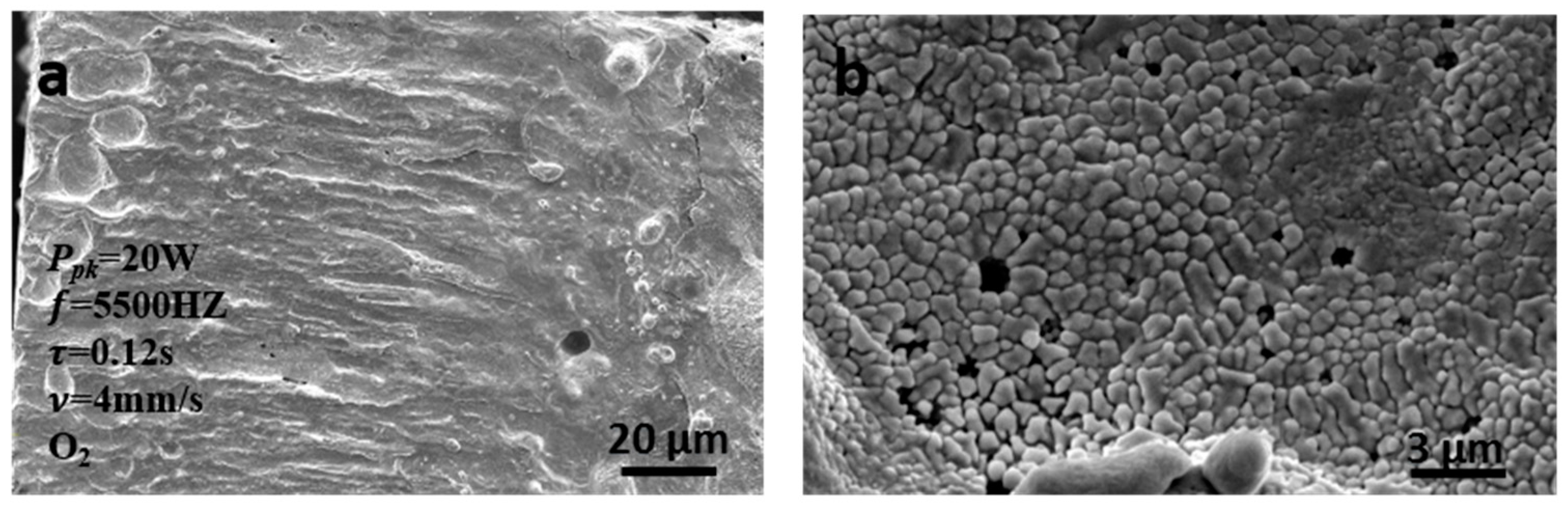
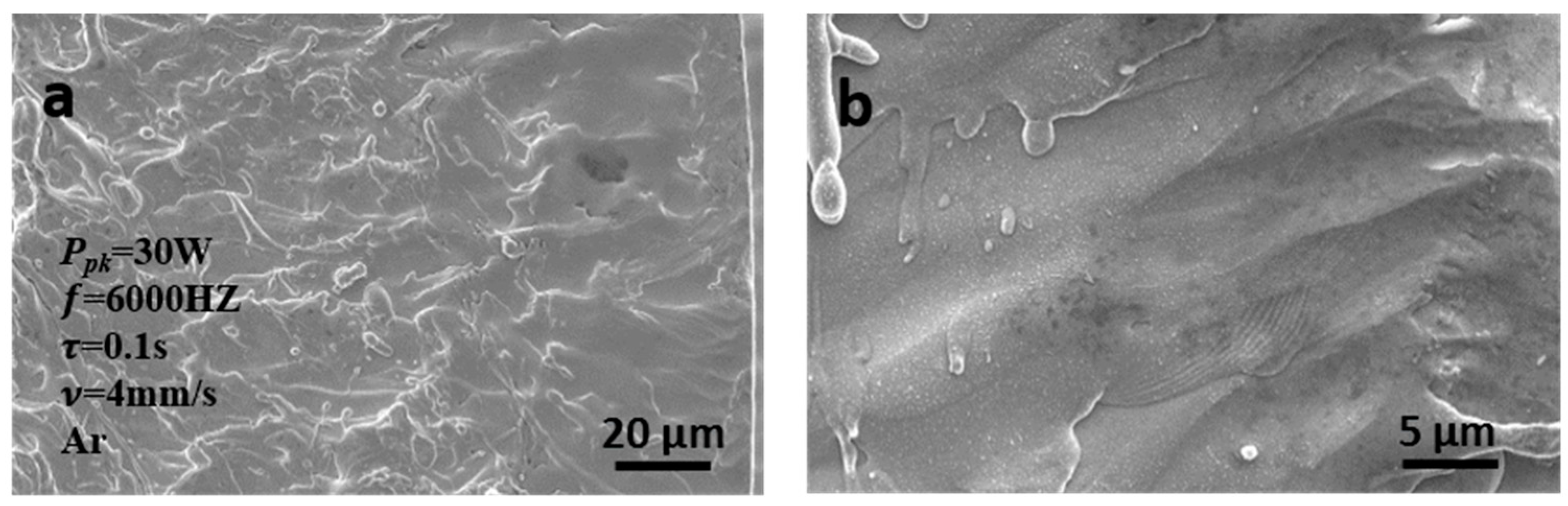
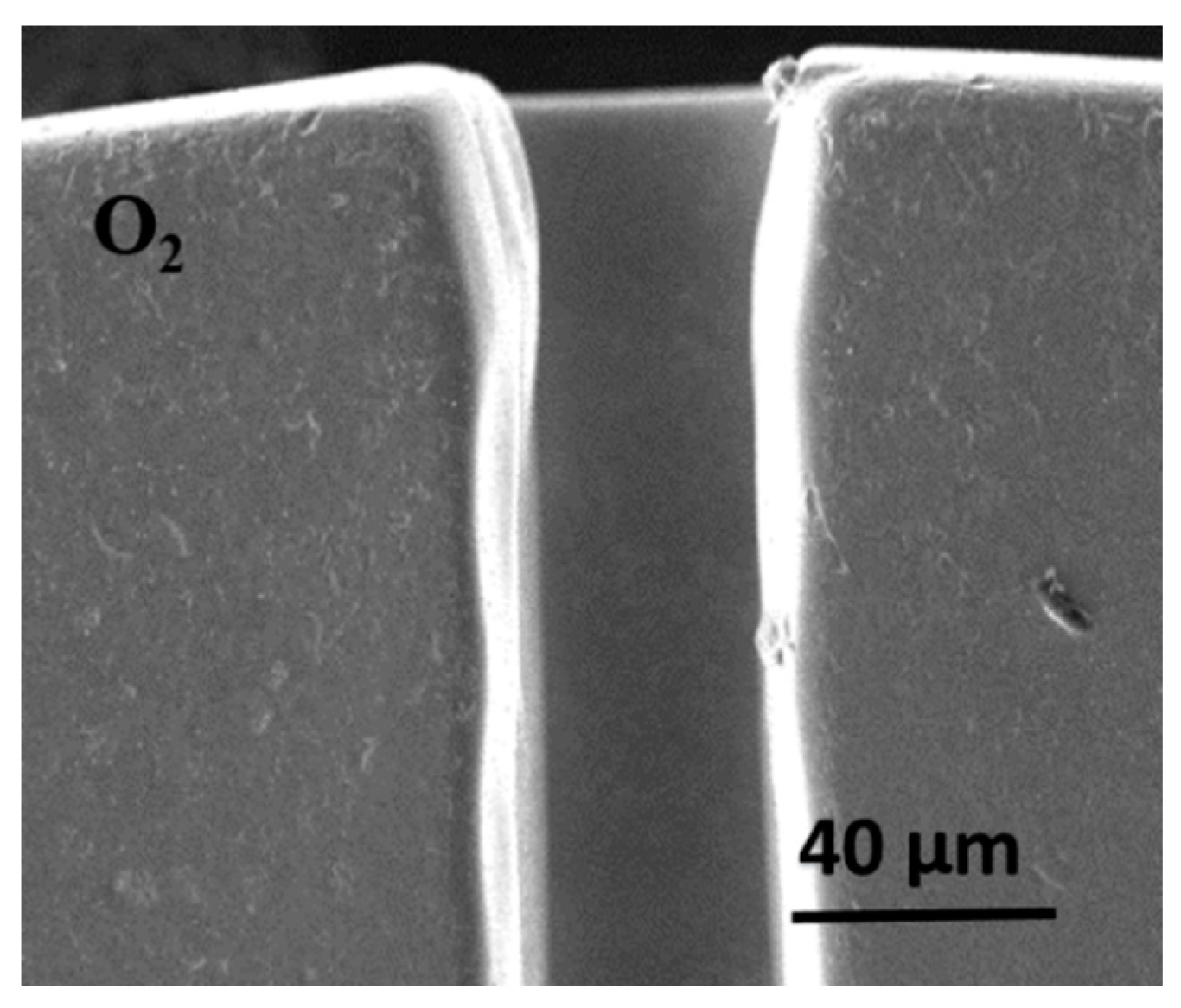
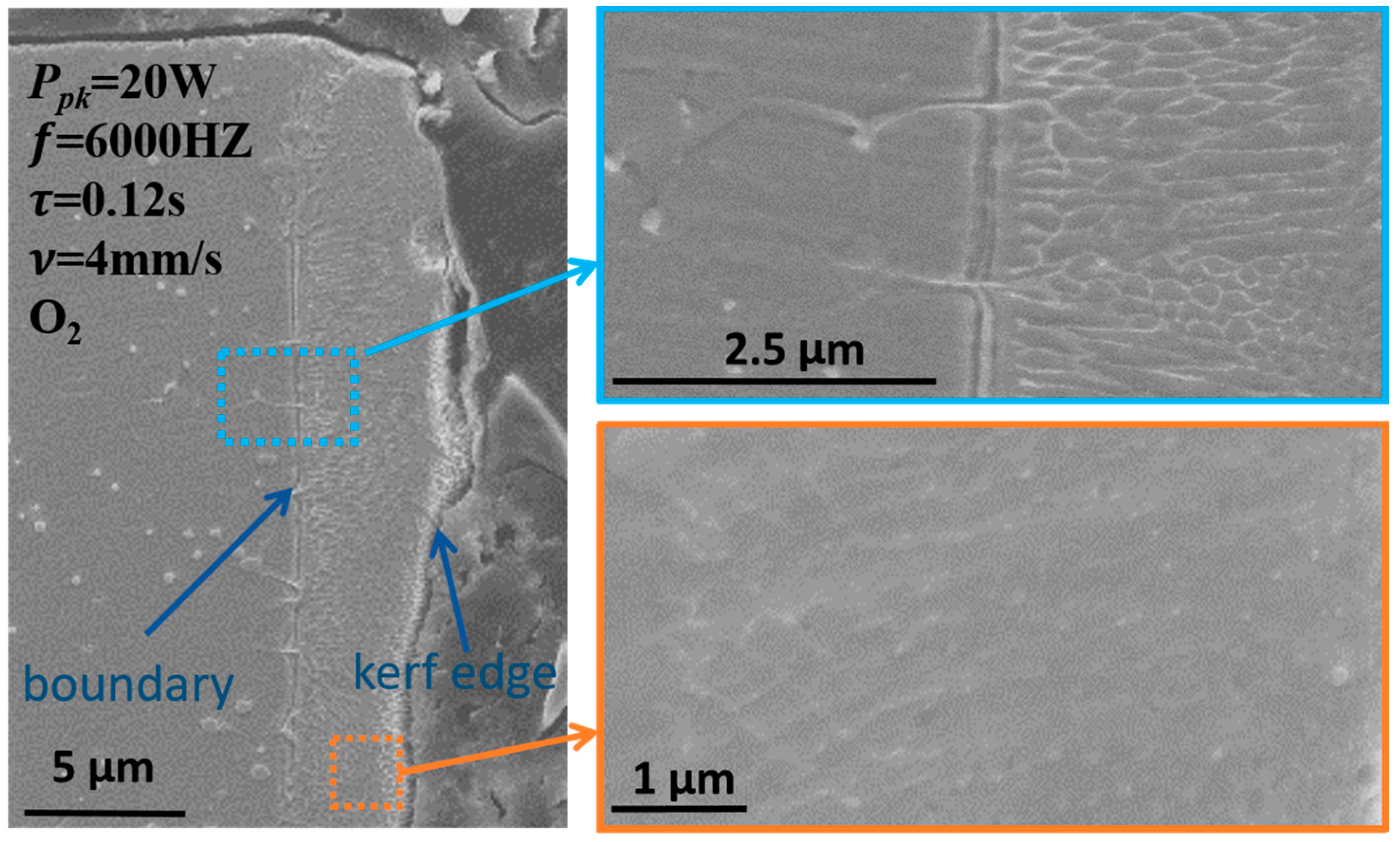
3.1.1. Cutting Surface Topography

Distinctions in the surface topographies between oxygen cuts and argon cuts were observed from both macro and micro views. Traditional striation topography could be observed on the cutting surface of the oxygen cuts. However, only layer topography was observed on the cutting surface of all argon cuts with different process parameters, as shown in Figure 2a and Figure 3a. In the micro view, abundant micrometer particles and voids were formed on the surface of the oxygen cuts, as shown in Figure 2b; meanwhile, no particles or voids could be observed on the argon cuts, and the surfaces were smooth and compact at the micrometer scale, as shown in Figure 3b.

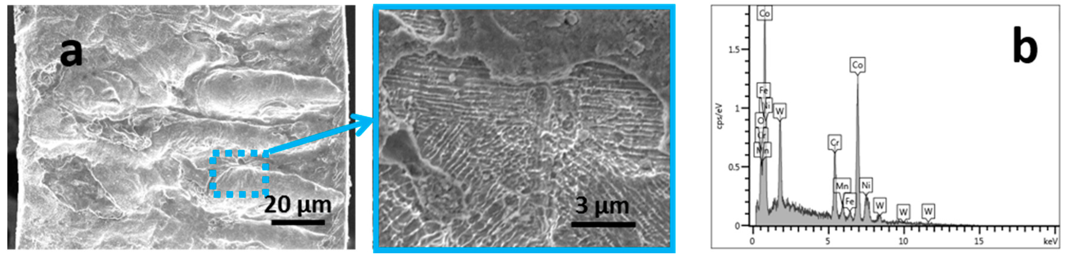
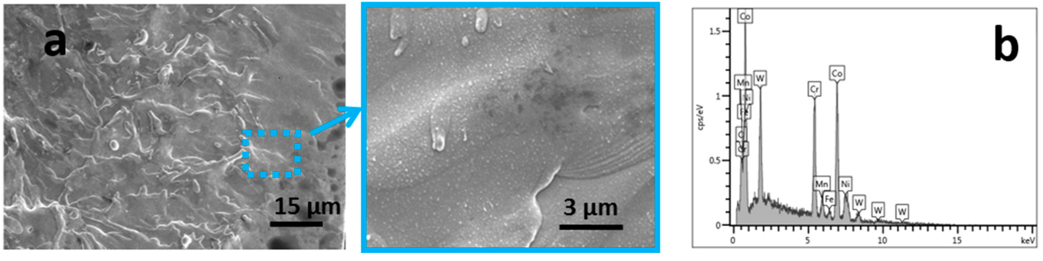
3.1.2. Element Compositions of the Cutting Surface

Table 4 and Table 5, respectively, show the chemical composition of the oxygen cuts surface and the argon cuts surface. “Original” in the table indicates the laser cuts without any post process, and “Pickling” represents the laser cuts processed using acid pickling.
About 33% oxygen was observed on the original oxygen cuts surface, and the contents of Cr, Co, as well as other elements, had changed. The chemical composition of the argon cuts surfaces showed little change, except for small amounts of oxygen (about 3.43%) and carbon (about 4.03%). The results demonstrated that the oxygen conditions can change the chemical composition of the cuts on the surface, while the argon conditions did not.
Acid is usually used for eliminating dross formation in the manufacturing process of stents, which was induced by laser cutting. The samples were etched in a solution (HF:HNO3:H2O, 2:15:83) for three hours at room temperature.
Figure 4 shows an image of the oxygen cuts with acid pickling. The particles and voids disappeared, and the surface topography changed compared with the original topography. Figure 5 shows the argon cuts with acid pickling, and the results showed that the acid pickling process had no influences on the surface topography.
The energy dispersion spectrum (EDS) results of the cuts processed with acid pickling are also shown in Table 3 and Table 4. For the oxygen cuts, the content of Cr and oxygen decreased remarkably. For the argon cuts, the elements composition was similar to the original surface. Chromic oxide is easy to dissolve in acid, and it could then be concluded that the particles on the oxygen cuts surface are oxides. Thereby, the dross formation on the oxygen cuts was easily removed by the acid pickling process. However, the acid pickling process had a limited influence on the argon cuts surface, and the dross formation was not eliminated.

3.1.3. Kerf Geometry and Dross Formation

Because of the recast layer and dross formation, irregular kerfs were observed in both the oxygen cuts and the argon cuts. Dross formation was also attached to the inside walls of the tubes, as shown in Figure 6. However, with the acid pickling process, a different phenomenon was observed. As shown in Figure 7, neat kerfs were obtained on the oxygen cuts and dross formation was eliminated. Unneat kerfs still existed on the argon cuts and dross formation did not decrease.
Unneat kerfs influence the stents’ dimension accuracy, as well as the surface quality. Dross formation is unacceptable in the manufacturing process of vascular stents, as it can be detrimental to a person’s health after being implanted into a vein.
For improving surface quality and eliminating HAZ, an electrochemical polishing process is necessary in the manufacturing process of metal stents, and is always followed by the acid pickling process. Using a polishing process, the salient materials on a stent’s surface can be removed; however, unneat kerfs and dross formation with argon cuts are harder to resolve through the polishing process. Thereby, oxygen is more suitable than argon as the assisting gas in the fiber laser cutting process of vascular stents. Figure 8 shows a sample processed with an electrochemical polishing step.

3.2. Influences of the Processing Parameters on Cutting Quality

Oxygen cuts were selected as research objects and the influences of the processing parameters on cutting quality were discussed in terms of surface topography, kerf width, and HAZ.

3.2.1. Surface Topography

As shown in Figure 9, different surface topographies were observed, which can be classified into three types: molten globule topography, striation topography, and molten pool topography. Molten globule topography has many globules on the cutting surface; striation topography is a regular topography in the fiber laser cutting process; and molten pool topography has irregular pools on the surface.
The repetition rate and pulse width have similar influences on surface topography; by increasing repetition rate (or pulse width), molten globule topography, striation topography, and molten pool topography appear successively.
The pulse’s wave shape is rectangle, and average power P ave can be calculated using Equation (2). The applied laser energy per cutting length ( E pcl ) is an important parameter that determines the heat input and mass of molten melt in the kerf section. E pcl can be calculated using Equation (3).
P ave = P pk × δ = P pk × τ × f
E pcl = P ave ν = P pk × τ × f ν
P pk represents the peak power controlled by the power modulated fiber laser, δ represents the duty ratio, τ represents the pulse width, f represents the laser frequency, and ν represents the cutting speed.
With a low repetition rate (or pulse width), the applied laser energy per cutting length is low, and the mass of the melt is limited. Most of the melt is ejected from the cutting kerf, accompanied with a small amount of melt being turned into globules, induced by the cooling and ejecting effect of the assisting gas. With intermediate E pcl , an appropriate amount of metal is molten and regular striation topography is formed because of the combined effects of high repetition rate, pulses, and assisting gas. With high repetition rate (or pulse width), an excess of heat is concentrated in the base material, an excessive mass of metal is molten, and then the melt with good fluidity is ejected, and thereby forming pool topography with the ejecting effect of the assisting gas.
Based on Equation (3), P pk has the same impact on E pcl as τ and f . However, different phenomena were observed in the cutting surface topography. As shown in Figure 9c, only striation topography was observed. In the given process parameter range, with increasing P pk , the striations became coarser and no molten globule topography or molten pool topography appeared. It could then be concluded that, although P pk has the same impact on E pcl as τ and f , it has slighter influences on the surface topography compared to τ and f . τ and f not only determine the value of E pcl , but also the heating and thermal conduction process. The heating and thermal conduction processes have underlying and complex impacts on cutting quality.
ν has more complex impacts on cutting quality, which not only influence the valve of E pcl , but also the cooling and ejecting effects. As shown in Figure 9d, with both low and high values for ν , globules could be observed on the cutting surface. With a low ν , E pcl is high, but the cooling effect is strengthened, and a topography combined with globules and pools was observed. Increasing ν will decrease E pcl and weaken the ejecting and cooling effects. With a high ν , a topography mixed with globules, striations, and pools was observed.

3.2.2. Kerf Width

Stents’ struts are very small, and their widths are about 150 250   μ m . To ensure the accuracy of strut width, path skewing of about one half the kerf width from the design path is necessary in the laser cutting process. To study the kerf width quantitatively, three positions, the entrance, middle, and exit of the kerf, were measured. To eliminate the impacts of machine rotating precision and measuring error, three kerfs around the ring were measured and then averaged. The samples were processed with acid before measuring. Figure 10 shows the influence of the process parameters on the kerf width.
Typical horn-kerfs were obtained in this research. All kerfs’ middle widths were narrower than the entrance and exit widths. Kerf width gradually increased with increasing repetition rate and pulse width. Increasing the repetition rate or pulse width increased the power density, as well as the mass of melt. Accordingly, the kerf width was enlarged. The increased power also made a wider kerf. However, the effect was not as obvious as increasing pulse width or repetition rate.
Increasing cutting speed resulted in a widening of kerf width. However, when the speed exceeded a specific value, the kerf was narrowed. Cutting speed influenced the mass of the melt, the cooling effect, combustion-supporting effect, as well as the ejecting strength. A low cutting speed would lead to a higher power density and a greater mass of melt, but the cooling effect was strong, which would take away the amount of heat and limit the mass of the melt. Thus, the cutting kerf was narrow. With a high cutting speed and low power density, the mass of molten melt was limited. Weakening the ejecting-strength with a high cutting speed also contributed to narrowing the cutting kerf, which is why the cutting kerf was narrow with both low and high cutting speeds.

3.2.3. Heat Affected Zone

Figure 11 shows a representative microstructure of cutting kerfs. A clear boundary could be seen between the substrate material and the re-crystallization zone. The substrate material’s grains were much larger than those of the re-crystallization zone. In the re-crystallization zone, the smallest grains were observed near the cutting kerf, which were induced by the fast cooling effect.
Based on the measurements of all cuts, the thickness of the re-crystallization zone ranged between 4 μm to 10 μm, and no noticeable difference in the HAZ size between different cuts were observed. The material in the HAZ had a different micro-structure than that of the substrate material, which should be removed using electrochemical polishing technology to ensure the material’s bio-mechanical properties.

4. Conclusions

Oxygen and argon have different impacts on the CoCr fiber laser cutting process. Oxygen helps molten melt burning, and an amount of oxide particles were observed on the surface of the oxygen cuts. Dross formation could be easily eliminated by the acid pickling process, and therefore neat cutting kerfs and non-dross formation could be obtained. Through the acid pickling process, the cut compositions were similar to the raw material. Argon is a type of inert gas, and, when protected with argon, the cutting process does not change the composition of the cuts. The cutting surface was compact and the acid pickling process had no effect on the cutting surface topography or dross formation. Dross formation and un-neat kerfs are challenges in argon cuts for manufacturing CoCr stents. Compared with inert gases, oxygen is preferential as the assisting gas in the fiber laser cutting of CoCr stents.
Three types of topographies were obtained in the oxygen cuts: molten globule topography, striation topography, and molten pool topography. Cuts with molten globule topography were difficult to separate from the tubes. In this case, in the manufacturing process of stents, fragments attach to the stent struts and lead to waste products. Molten pool topography is also not ideal, as pools on the cutting surface lower the surface quality. Striation topography is therefore the best choice.
The repetition rate and pulse width had similar impacts on cutting quality, including the surface topography and cutting kerf. The power had less of an impact on cutting quality than repetition rate and pulse width because of the cutting mechanism of pulsed lasers. Cutting speed had a more complex impact on cutting quality because it not only influenced the value of E pcl , but also the cooling effect, ejecting effect, and combustion-supporting effects.
In conclusion, a guideline regarding profiling CoCr stents with fiber lasers can be given: first, use oxygen as the assisting gas and confirm the gas pressure; the gas should eject the molten melt smoothly, and cannot bend the stents as stents are always flexible. Second, melt the right mass of metal with a high frequency, low pulse width, suitable power, and speed. Third, adjust the pulse or frequency to obtain striation topography.

Acknowledgments

This work was financially supported by Open Research Fund of Jiangsu Provincial Key Laboratory for Interventional Medical Devices (jr1505), International Science and Technology Cooperation Project of Huaian City (HAC201615), Natural Science Foundation of the Higher Education Institutions of Jiangsu Province (13KJB460002) and Prospective Joint Research Project of Jiangsu Province (BY2015051-04).

Author Contributions

Lei Liu conceived and designed the experiments; Dongbo Li and Yufu Zhu performed the experiments; Yifei Tong analyzed the data and wrote the paper.

Conflicts of Interest

The authors declare no conflict of interest and the founding sponsors had no role in the design of the study; in the collection, analyses, or interpretation of data; in the writing of the manuscript, and in the decision to publish the results.

References

  1. Azaouzi, M.; Makradi, A.; Belouettar, S. Deployment of a self-expanding stent inside an artery: A finite element analysis. Mater. Des. 2012, 41, 410–420. [Google Scholar] [CrossRef]
  2. Weiss, S.; Mitevski, B. Microstructure and deformation of coronary stents from cocr-alloys with different designs. Materials 2015, 8, 2467–2479. [Google Scholar] [CrossRef]
  3. Hung, C.; Chang, F.; Chang, T.; Chang, Y.; Huang, K.; Liang, P. Micromachining NiTi tubes for use in medical devices by using a femtosecond laser. Opt. Laser Eng. 2015, 66, 34–40. [Google Scholar] [CrossRef]
  4. Yung, K.C.; Zhu, H.H.; Yue, T.M. Theoretical and experimental study on the kerf profile of the laser micro-cutting NiTi shape memory alloy using 355 nm Nd: YAG. Smart Mater. Struct. 2005, 14, 337. [Google Scholar] [CrossRef]
  5. Pfeifer, R.; Herzog, D.; Hustedt, M.; Barcikowski, S. PulsedNd: YAG laser cutting of NiTi shape memory alloys—Influence of process parameters. J. Mater. Process. Technol. 2010, 210, 1918–1925. [Google Scholar] [CrossRef]
  6. Meijer, J.; Du, K.; Gillner, A.; Hoffmann, D.; Kovalenko, V.S.; Masuzawa, T.; Ostendorf, A.; Poprawe, R.; Schulz, W. Laser machining by short and ultrashort pulses, state of the art and new opportunities in the age of the photons. CIRP Ann.-Manuf. Technol. 2002, 51, 531–550. [Google Scholar] [CrossRef]
  7. Sudheer, S.K.; Kothwala, D.; Prathibha, S.; Engineer, C.; Raval, A.; Kotadia, H. Laser microfabrication of L605 cobalt-chromium cardiovascular stent implants with modulated pulsed Nd: YAG laser. J. Microlithogr. Microfabr. Microsyst. 2008, 7, 1463. [Google Scholar] [CrossRef]
  8. Raval, A.; Choubey, A.; Engineer, C.; Kothwala, D. Development and assessment of 316LVM cardiovascular stents. Mater. Sci. Eng. A Struct. 2004, 386, 331–343. [Google Scholar] [CrossRef]
  9. Kleine, K.F.; Watkins, K.G. Fiber laser for micro cutting of metals. Proc. SPIE 2003, 4974, 185. [Google Scholar] [CrossRef]
  10. Meng, H.; Liao, J.; Zhou, Y.; Zhang, Q. Laser micro-processing of cardiovascular stent with fiber laser cutting system. Opt. Laser Technol. 2009, 41, 300–302. [Google Scholar] [CrossRef]
  11. Muhammad, N.; Whitehead, D.; Boor, A.; Li, L. Comparison of dry and wet fibre laser profile cutting of thin 316L stainless steel tubes for medical device applications. J. Mater. Process. Technol. 2010, 210, 2261–2267. [Google Scholar] [CrossRef]
  12. Demir, A.G.; Previtali, B.; Biffi, C.A. Fibre laser cutting and chemical etching of AZ31 for manufacturing biodegradable stents. Adv. Mater. Sci. Eng. 2013, 2013, 692635. [Google Scholar] [CrossRef]
  13. Demir, A.G.; Previtali, B.; Colombo, D.; Ge, Q.; Vedani, M.; Petrini, L.; Wu, W.; Biffi, C.A. Fiber Laser Micromachining of Magnesium Alloy Tubes for Biocompatible and Biodegradable Cardiovascular Stents. In Proceedings of the SPIE 8237, Fiber Lasers IX: Technology, Systems, and Applications, San Francisco, CA, USA, 21 January 2012; Volume 82373, pp. 1844–1864. [Google Scholar] [CrossRef]
  14. Fu, C.H.; Liu, J.F.; Guo, A. Statistical characteristics of surface integrity by fiber laser cutting of Nitinol vascular stents. Appl. Surf. Sci. 2015, 353, 291–299. [Google Scholar] [CrossRef]
  15. Sweeney, C.A.; Dunne, F.P.E.; McHugh, P.E.; Leen, S.B. Micro-scale testing and micromechanical modelling for high cycle fatigue of CoCr stent material. J. Mech. Behav. Biomed. Mater. 2015, 46, 244–260. [Google Scholar] [CrossRef] [PubMed]
  16. Muhammad, N.; Whitehead, D.; Boor, A.; Oppenlander, W.; Liu, Z.; Li, L. Picosecond laser micromachining of nitinol and platinum–iridium alloy for coronary stent applications. Appl. Phys. A 2012, 106, 607–617. [Google Scholar] [CrossRef]
  17. Muhammad, N.; Li, L. Underwater femtosecond laser micromachining of thin nitinol tubes for medical coronary stent manufacture. Appl. Surf. Sci. 2012, 107, 849–861. [Google Scholar] [CrossRef]
  18. Demir, A.G.; Previtali, B. Additive manufacturing of cardiovascular CoCr stents by selective laser melting. Mater. Des. 2017, 119, 338–350. [Google Scholar] [CrossRef]
  19. Liu, L.; Li, D.B.; Tong, Y.F.; Zhu, Y.F. Fiber laser micromachining of thin NiTi tubes for shape memory vascular stents. Appl. Phys. A 2016, 122, 1–9. [Google Scholar] [CrossRef]
Figure 1. Cut geometry.
Applsci 07 00608 g001
Figure 2. Surface topography of the sample that was cut with oxygen: (a) macro view; and (b) micro view.
Applsci 07 00608 g002
Figure 3. Surface topography of the sample that was cut with argon: (a) macro view; and (b) micro view.
Applsci 07 00608 g003
Figure 4. (a) The image of the oxygen cuts with acid pickling; (b) energy dispersion spectrum (EDS).
Applsci 07 00608 g004
Figure 5. (a) The image of the argon cuts with acid pickling; (b) energy dispersion spectrum (EDS).
Applsci 07 00608 g005
Figure 6. Kerf geometry and dross formation of the cuts before the acid pickling process: (a) oxygen cut; and (b) argon cut.
Applsci 07 00608 g006
Figure 7. Kerf cross-sections of the cuts with the acid pickling process: (a) oxygen cut; and (b) argon cut.
Applsci 07 00608 g007
Figure 8. Topography of the oxygen sample processed with electrochemical polishing.
Applsci 07 00608 g008
Figure 9. The influences of process parameters on surface topography: (a) repetition rate; (b) pulse width; (c) power; (d) cutting speed.
Applsci 07 00608 g009
Figure 10. Influence of the process parameters on the kerf width: (a) repetition rate; (b) pulse width; (c) power; (d) cutting speed.
Applsci 07 00608 g010
Figure 11. The microstructure of cutting kerfs with metallographic preparation.
Applsci 07 00608 g011
Table 1. Chemical composition of CoCr tubes.
ElementCrCoCSiPSMnNiFeW
Percentage 19.9 % Balance 0.07 % 0.06 % 0.025 % 0.01 % 1.2 % 10.1 % 1.7 % 14.1 %
Table 2. Process parameters for Set A.
Cut #Power
( P p k ) W
Repetition Rate
( f ) Hz
Pulse Width
( % τ ) ms
Speed
( ν ) mm/s
Cut #Power
( P set )
Repetition Rate
( f ) Hz
Pulse Width
( τ ) ms
Speed
( ν ) mm/s
12045000.124131760000.124
22050000.124141860000.124
32055000.124151960000.124
42060000.124162060000.124
52065000.124172160000.124
62075000.124182260000.124
72060000.094192060000.123
82060000.104202060000.123.5
92060000.114212060000.124
102060000.124222060000.124.5
112060000.134232060000.125
122060000.144242060000.125.5
Table 3. Process parameters for Set B.
Cut #Power
( P pk ) W
Repetition Rate
( f ) Hz
Pulse Width
( τ ) ms
Speed
( ν ) mm/s
Cut #Power
( P set )
Repetition Rate
( f ) Hz
Pulse Width
( τ ) ms
Speed
( ν ) mm/s
13045000.104132560000.104
23050000.1041427.560000.104
33055000.104153060000.104
43060000.1041632.560000.104
53065000.104173560000.104
63075000.1041837.560000.104
73060000.084193060000.103.3
83060000.094203060000.103.65
93060000.104213060000.104
103060000.114223060000.104.35
113060000.124233060000.104.7
123060000.134243060000.105.0
Table 4. Chemical composition on the oxygen cuts surface.
OriginalCrCoOMnNiFeW
30.11   % 21.80   % 32.93   % 1.61   % 2.83   % 1.09 % 9.63   %
PicklingCrCoOMnNiFeW
12.64   % 53.72   % 3.94   % 1.29   % 11.44   % 2.17   % 14.80%
Table 5. Chemical composition on the argon cuts surface.
OriginalCrCoOCSMnNiFeW
19.29   % 45.51%3.43% 4.03   % 0.02% 0.91   % 10.43% 1.31   % 14.89   %
PicklingCrCoOCSMnNiFeW
19.75   % 46.73   % 4.38   % 0 0 1.55   % 9.39   % 2.18   % 16.01   %

