
Effects of Nozzle Configuration on Rock Erosion Under a Supercritical Carbon Dioxide Jet at Various Pressures and Temperatures

Abstract
:1. Introduction
2. Theoretical Background
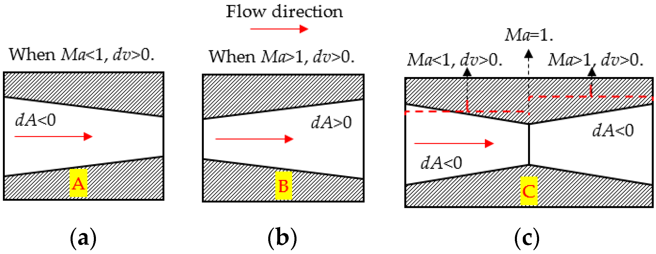
2.1. Acceleration Mechanisms of Compressible Flow Inside the Nozzle
2.2. Jet-Flow Characteristics Outside the Nozzle
3. Materials and Methods
3.1. Materials
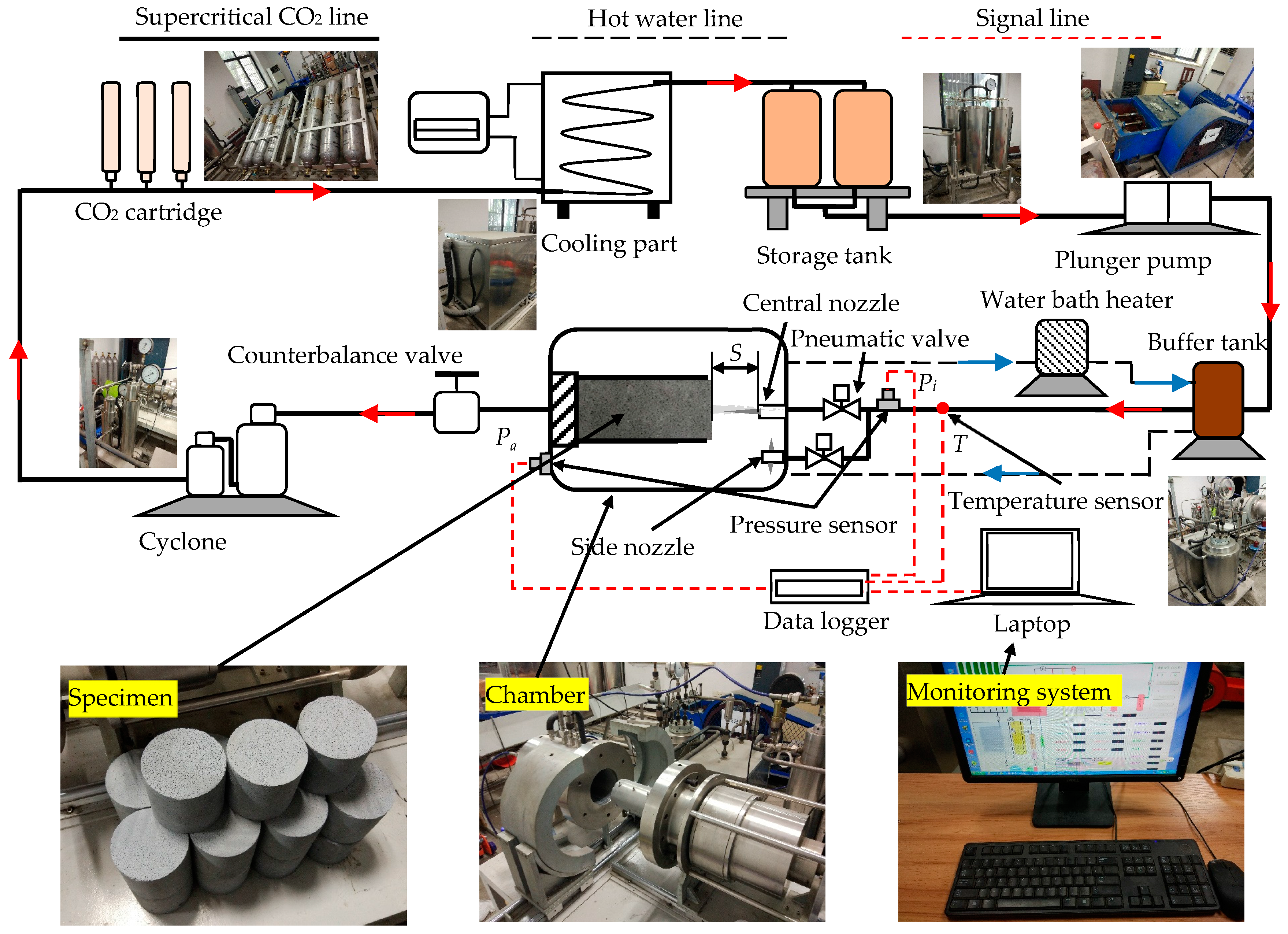
3.2. Facilities
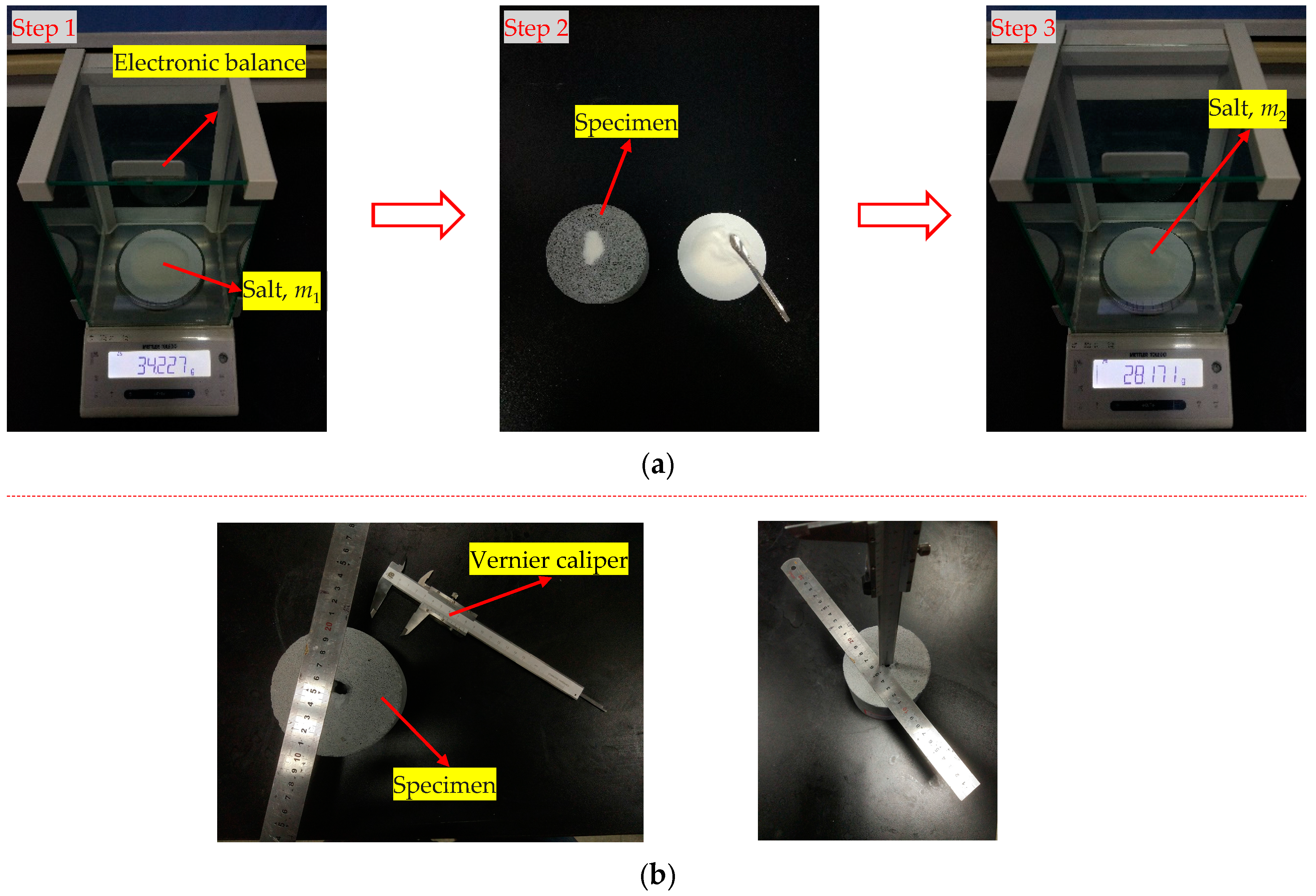
3.3. Experimental Procedures
3.4. Experimental Uncertainty
4. Results
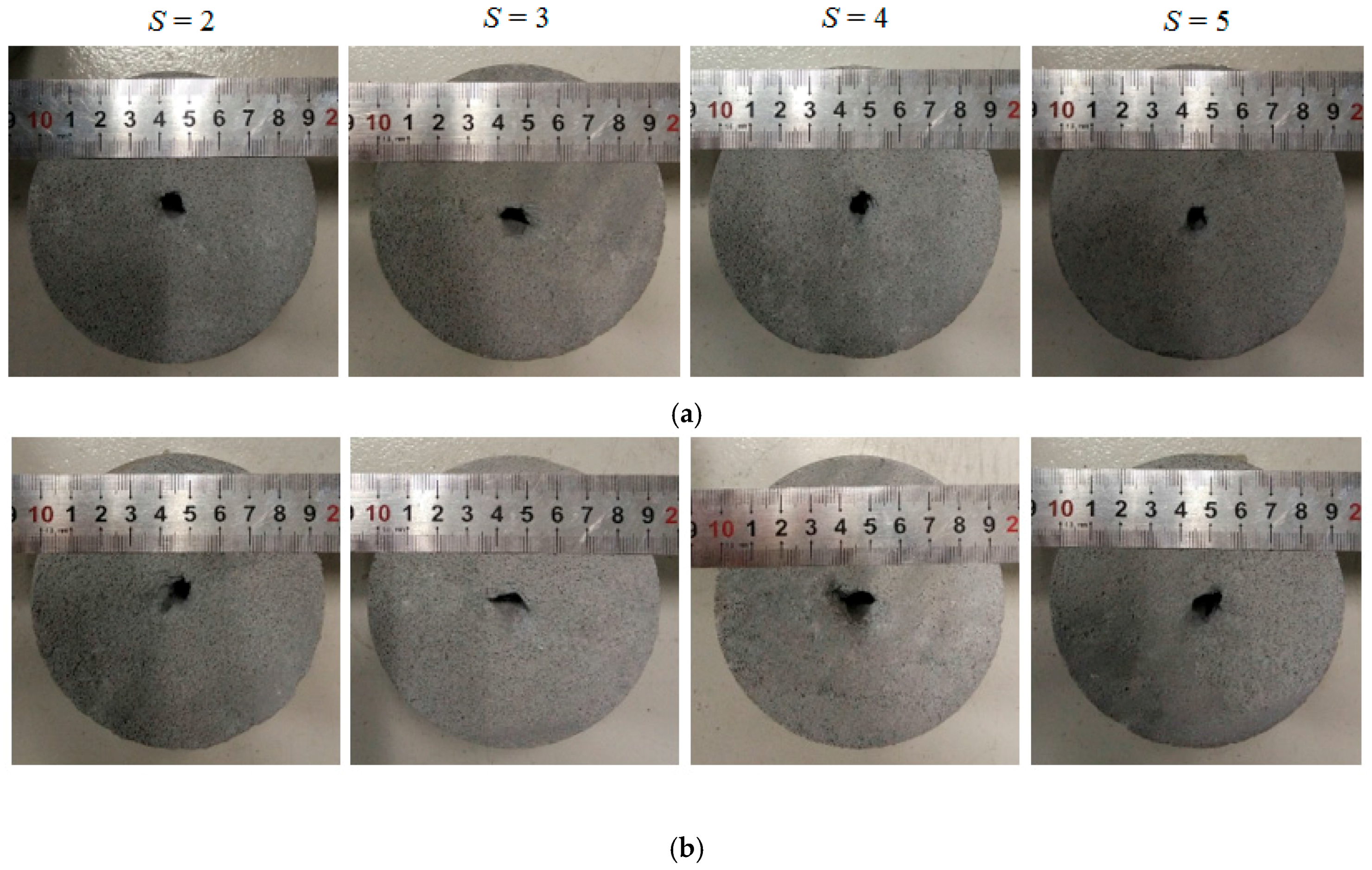
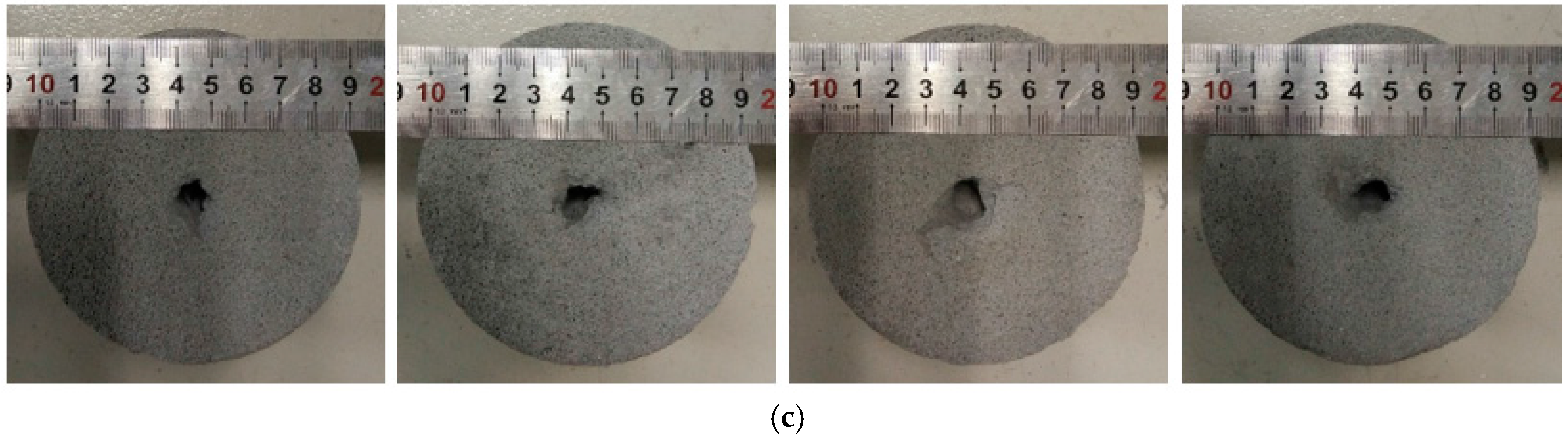
4.1. Macroscopic Appearances of Eroded Specimens
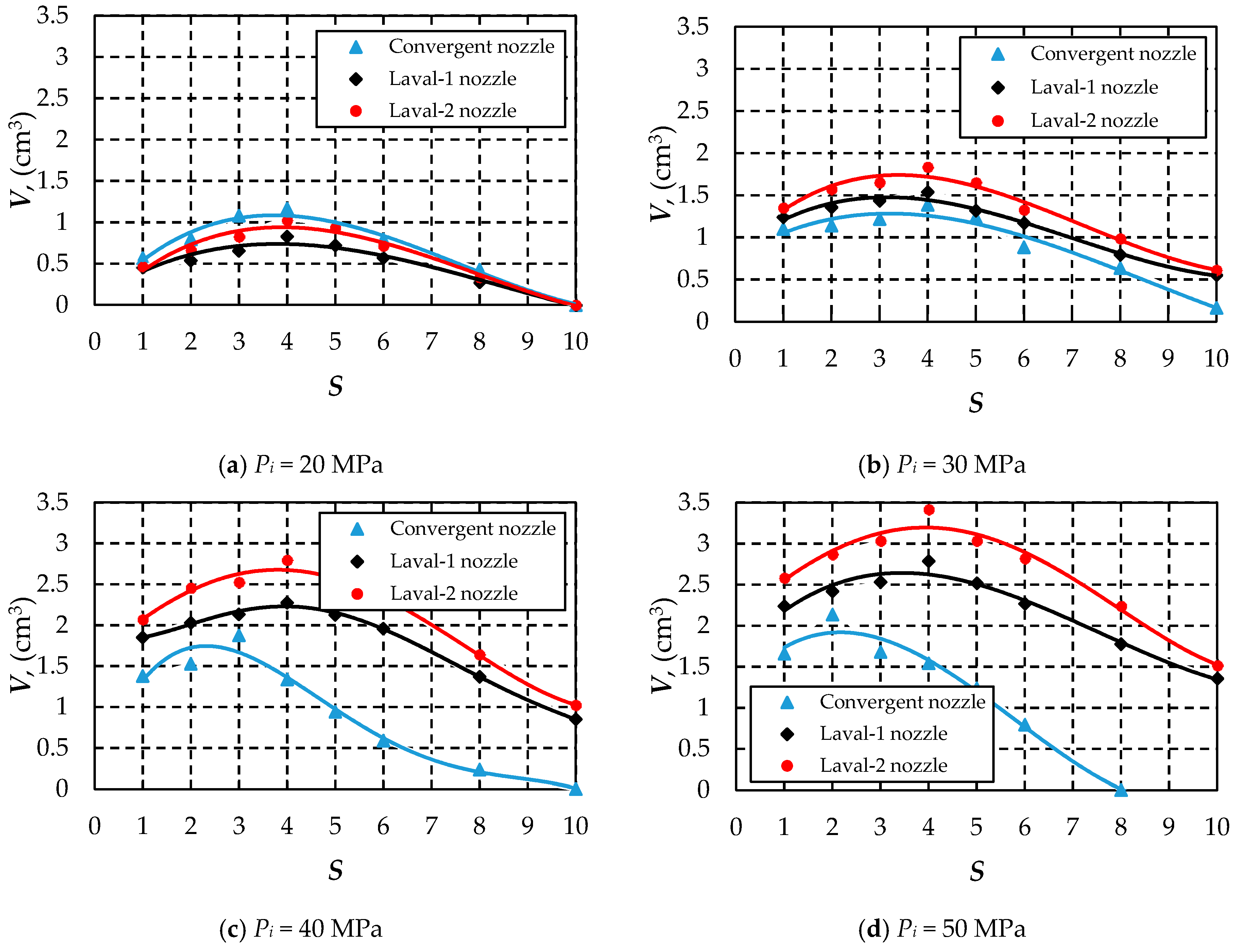
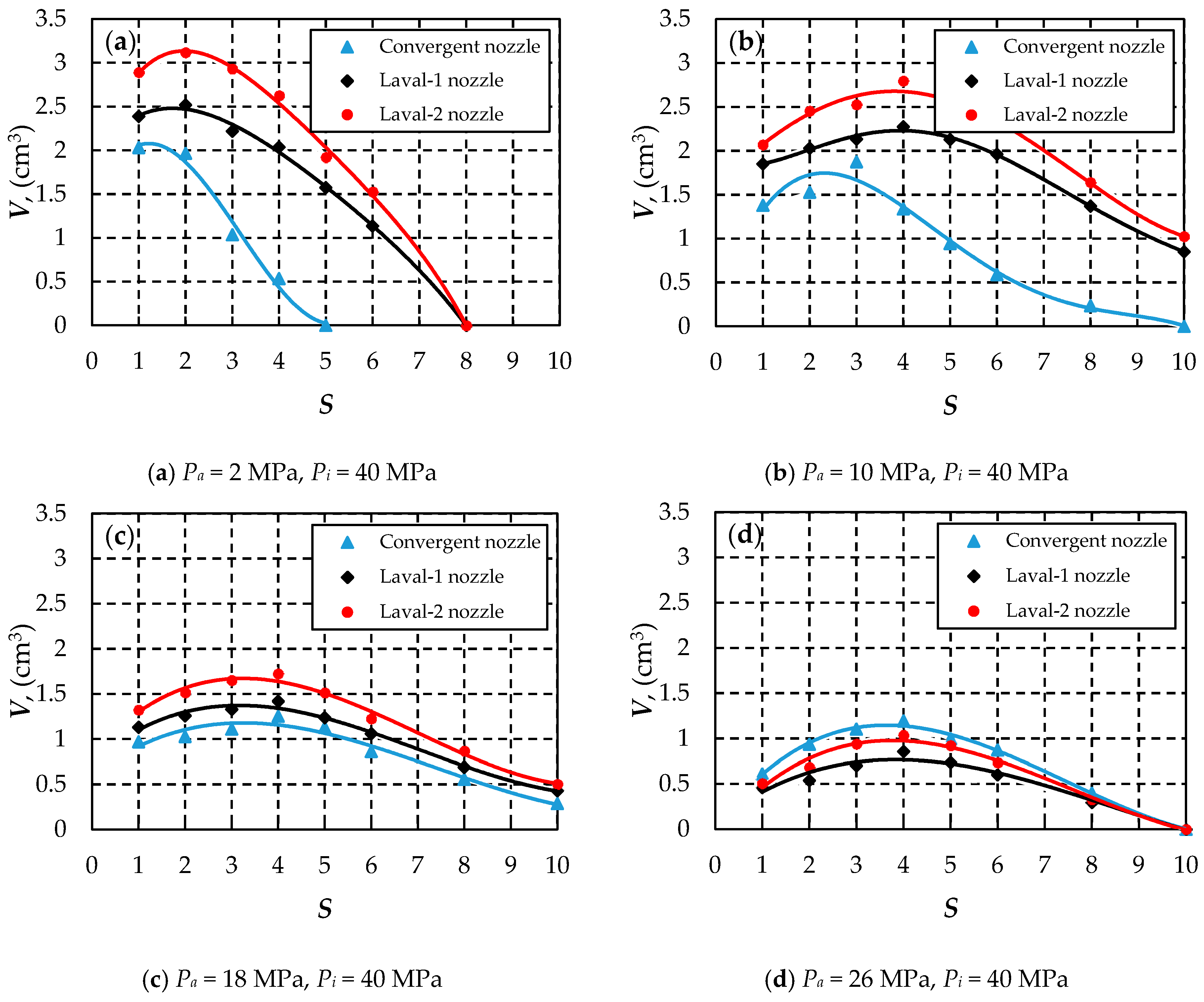
4.2. Effect of Nozzle Configuration Under Different Inlet Pressures
4.3. Effect of Nozzle Configuration Under Different Ambient Pressures and Constant Inlet Pressure
4.4. Effect of Nozzle Configuration Under Different Ambient Pressures and Constant Pressure Drop
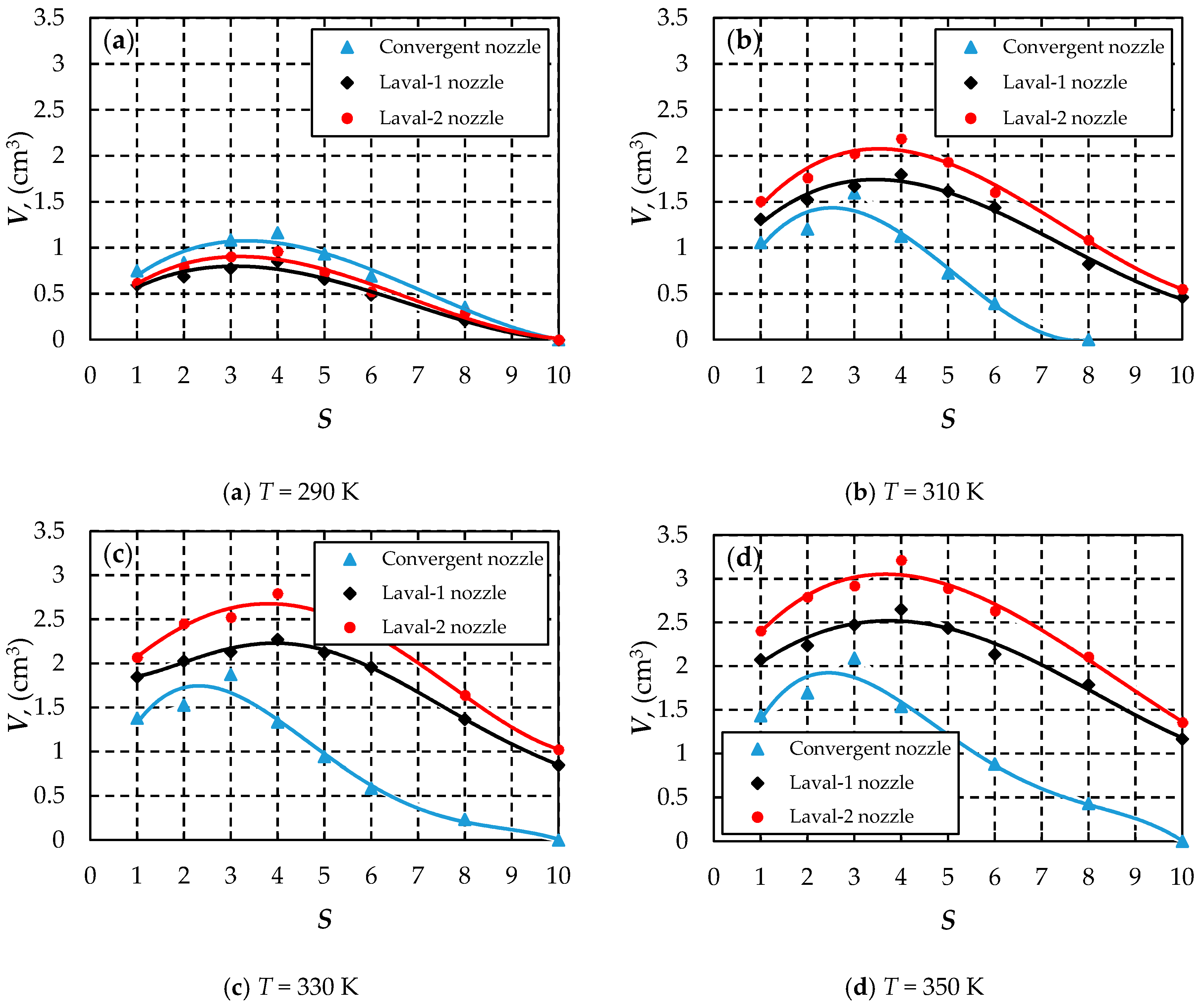
4.5. Effect of Nozzle Configuration Under Different Fluid Temperatures
5. Discussion
6. Conclusions
- The macroscopic appearances of specimens eroded by SC-CO2 jets discharging from different nozzles display similar typical “drilling type” damage. Small pieces of rock breakage can be observed around the erosion pits caused by the Laval nozzles, while the pits eroded by the convergent nozzle are relatively flat and smooth.
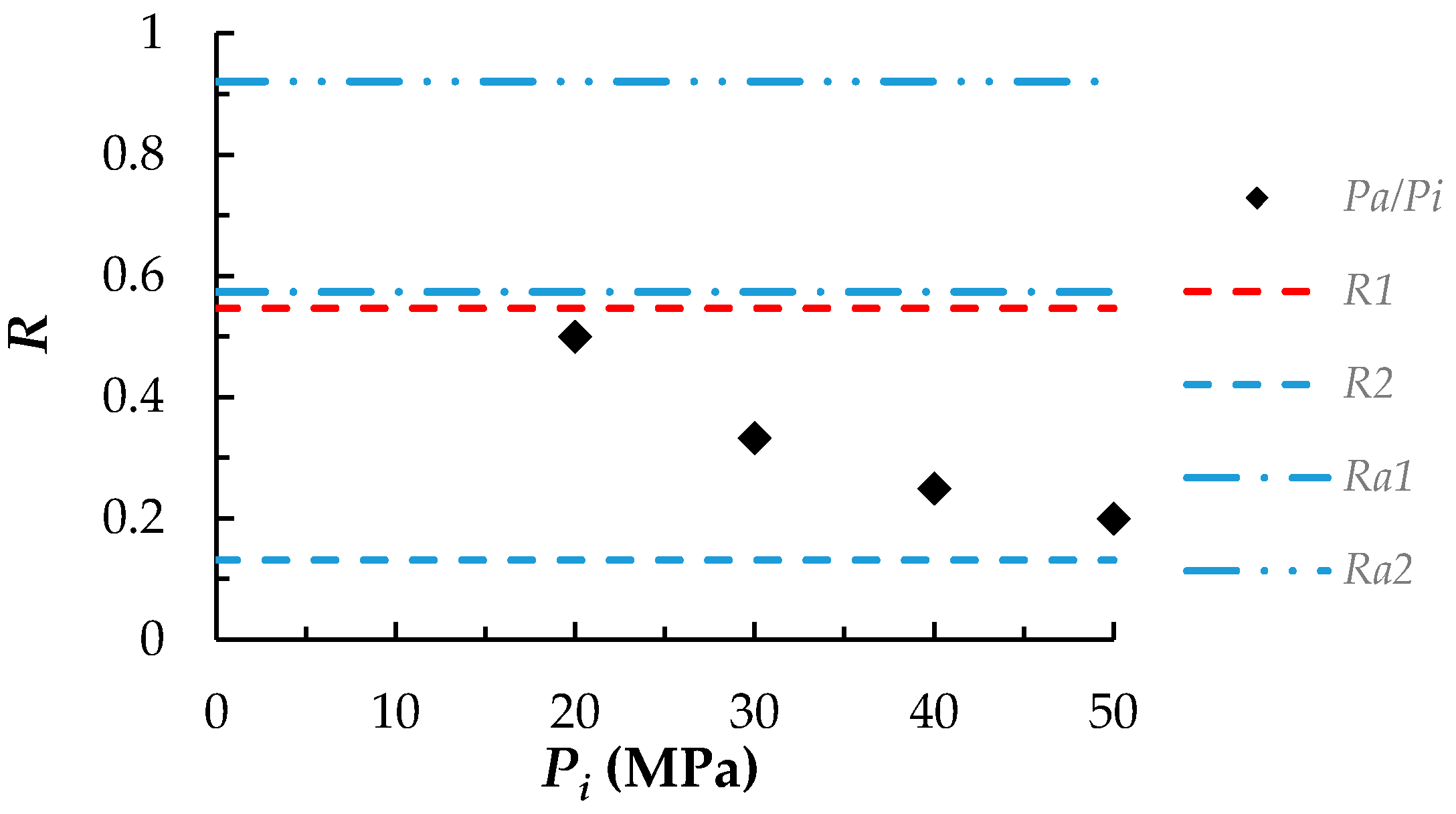
- Compared with the convergent nozzle, the Laval nozzles can enhance the erosion ability of the SC-CO2 jet more and more significantly with increasing inlet pressure; whilst at relatively lower inlet pressure of 20 MPa, they reduce the erosion capacity.
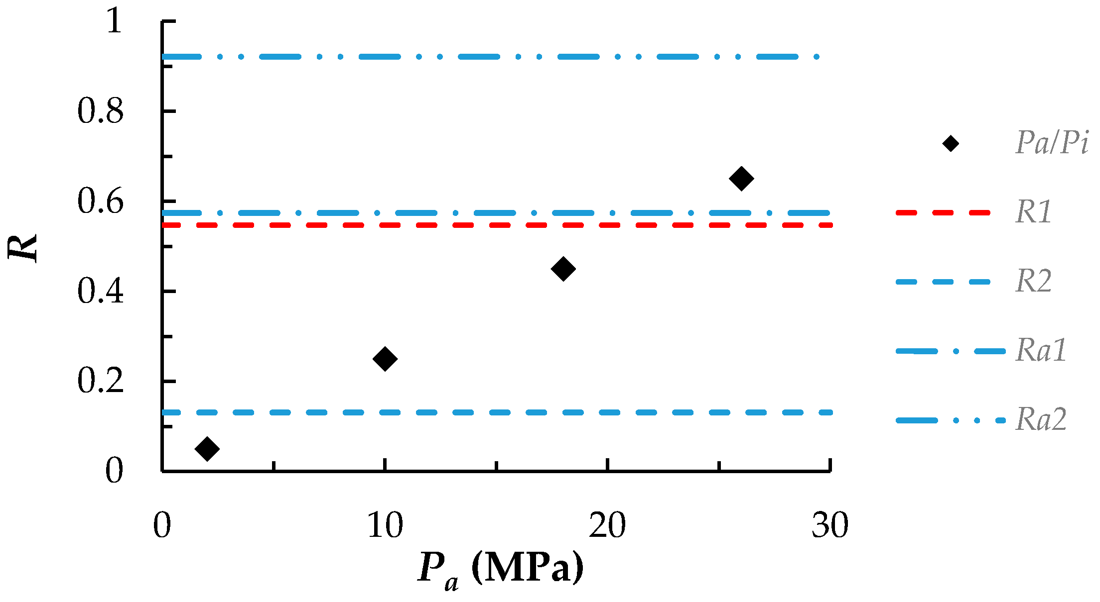
- Under constant inlet pressure, the maximum increments of erosion capability caused by the Laval nozzles are reduced by the increasing ambient pressure. Besides, at ambient pressure of 26 MPa, the Laval nozzles turn to weaken the erosion ability. When ΔP is constant, the enhancements caused by the Laval nozzles decrease with growing ambient pressure.
- As the fluid temperature rises, the enhancements of erosion capacity produced by the Laval nozzles increase. Moreover, the Laval nozzles weaken the erosion intensity at a temperature of 290 K, which puts CO2 in liquid state.
- The SC-CO2 jet issuing from the Laval-2 nozzle with a smooth inner profile always has a greater erosion ability than that discharging from the Laval-1 nozzle.
Acknowledgments
Author Contributions
Conflicts of Interest
Nomenclatures
| Pc | critical pressure of CO2, MPa |
| Tc | critical temperature of CO2, K |
| A | cross-sectional area of the nozzle flow path, m3 |
| Ma | Mach number |
| v | flow velocity, m/s |
| Pi | inlet pressure, MPa |
| Pa | ambient pressure, MPa |
| R1, R2, Ra1, Ra2 | critical pressure ratios |
| k | adiabatic exponent |
| Pc1 | critical ambient pressure of convergent nozzle, MPa |
| Pc2 | critical ambient pressure of Laval nozzle, MPa |
| π(λe) | gas dynamics function |
| λe | supersonic velocity coefficient |
| λe′ | subsonic velocity coefficient |
| Rc | ratio of the cement mortar |
| ρa | density of the artificial core, kg/m3 |
| σa | compressive strength of the artificial core, MPa |
| Ea | elastic modulus of the artificial core, GPa |
| υa | Poisson’s ratio of the artificial core |
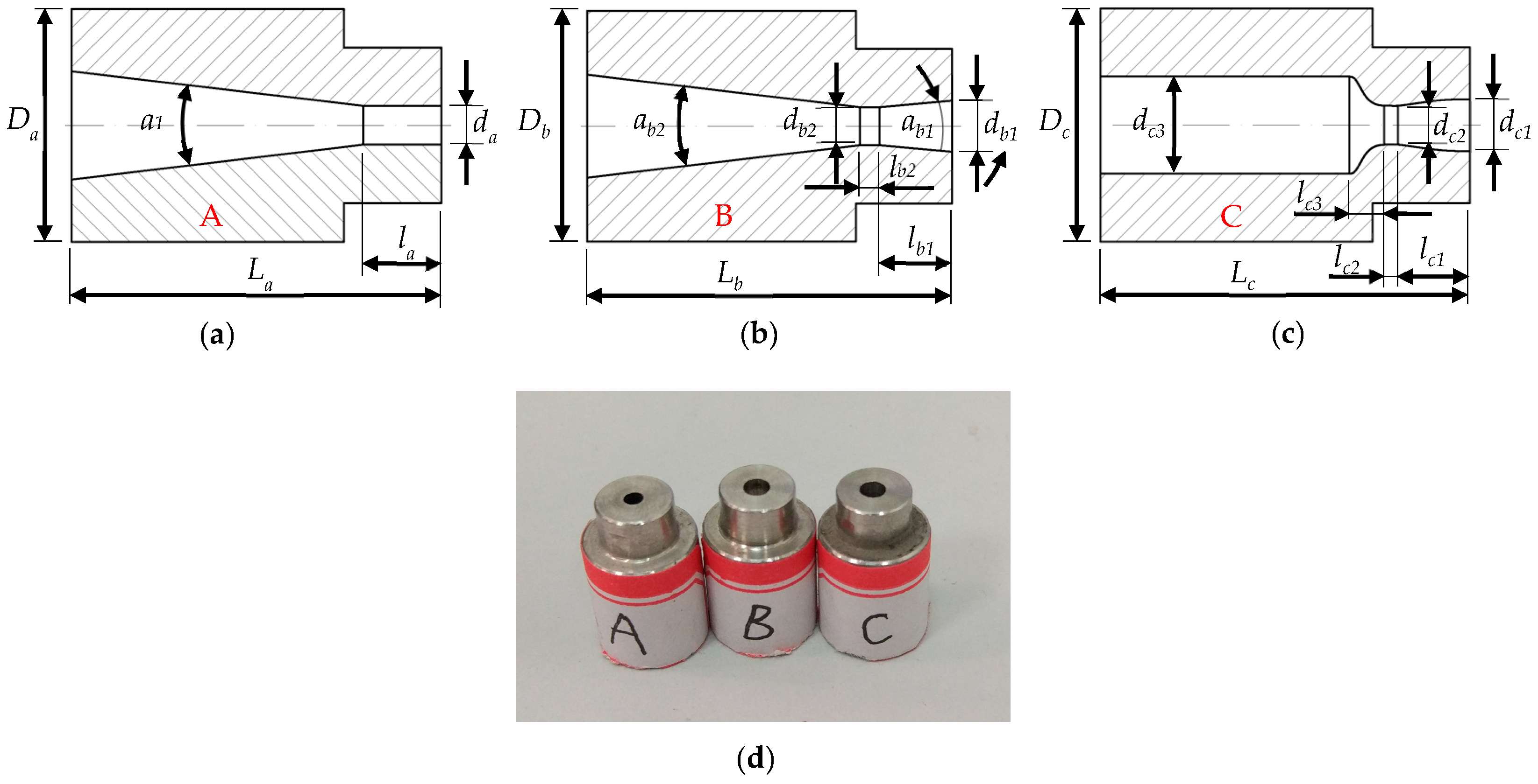
| a1, da, la, Da, La | size parameters of the convergent nozzle |
| ab1, ab2, db1, db2, lb2, lb1, Db, Lb | size parameters of the Laval-1 nozzle |
| dc1, dc2, dc3, lc1, lc2, lc3, Dc, Lc | size parameters of the Laval-2 nozzle |
| S | dimensionless standoff distance |
| V | erosion volume, mm3 |
| ρs | density of the salt, g/cm3 |
| m1, m2 | mass of salt, kg |
| R | ratio of the ambient pressure to the inlet pressure |
References
- Knez, Ž.; Markočič, E.; Leitgeb, M.; Primožič, M.; Hrnčič, M.K.; Škerget, M. Industrial applications of supercritical fluids: A review. Energy 2014, 77, 235–243. [Google Scholar] [CrossRef]
- Bellan, J. Supercritical (and subcritical) fluid behavior and modeling: Drops, streams, shear and mixing layers, jets and sprays. Prog. Energ. Combust. 2000, 26, 329–366. [Google Scholar] [CrossRef]
- Shen, Z.; Wang, H.; Li, G. Feasibility analysis of coiled tubing drilling with supercritical carbon dioxide. Petrol. Explor. Dev. 2010, 37, 743–747. [Google Scholar] [CrossRef]
- Gupta, A.P.; Gupta, A.; Langlinais, J. Feasibility of supercritical carbon dioxide as a drilling fluid for deep underbalanced drilling operation. Proceedings of SPE Annual Technical Conference and Exhibition, Dallas, TX, USA, 9–12 October 2005. [Google Scholar] [CrossRef]
- ALAdwani, F.A. Mechanistic Modeling of an Underbalanced Drilling Operation Utilizing Supercritical Carbon Dioxide. Ph. D. Thesis, Louisiana State University, LA, USA, August 2007. [Google Scholar]
- Middleton, R.S.; Carey, J.W.; Currier, R.P.; Hyman, J.D.; Kang, Q.; Karra, S.; Jiménez-Martínez, J.; Porter, M.L.; Viswanathan, H.S. Shale gas and non-aqueous fracturing fluids: Opportunities and challenges for supercritical CO2. Appl. Energy 2015, 147, 500–509. [Google Scholar] [CrossRef]
- Wang, H.; Li, G.; Shen, Z. A feasibility analysis on shale gas exploitation with supercritical carbon dioxide. Energ. Source A 2012, 34, 1426–1435. [Google Scholar] [CrossRef]
- Fang, C.; Chen, W.; Amro, M. Simulation study of hydraulic fracturing using super critical CO2 in shale. Proceedings of Abu Dhabi International Petroleum Exhibition and Conference, Abu Dhabi, UAE, 10–13 November 2014. [Google Scholar] [CrossRef]
- Du, Y.K.; Wang, R.H.; Ni, H.J.; Li, M.K.; Song, W.Q.; Song, H.F. Determination of rock-breaking performance of high-pressure supercritical carbon dioxide jet. J. Hydrodyn. 2012, 24, 554–560. [Google Scholar] [CrossRef]
- Lv, Q.; Long, X.P.; Kang, Y.; Xiao, L.Z.; Wu, W. Numerical investigation on the expansion of supercritical carbon dioxide jet. IOP Conf. Ser. Matesr. Sci. Eng. 2013, 52, 072011. [Google Scholar] [CrossRef]
- Tian, S.C.; He, Z.G.; Li, G.S.; Wang, H.Z.; Shen, Z.H.; Liu, Q.L. Influences of ambient pressure and nozzle-to-target distance on SC-CO2 jet impingement and perforation. J. Nat. Gas Sci. Eng. 2016, 29, 232–242. [Google Scholar] [CrossRef]
- Wang, H.Z.; Li, G.S.; Shen, Z.H.; Tian, S.C.; Sun, B.J.; He, Z.G.; Lu, P.Q. Experiment on rock breaking with supercritical carbon dioxide jet. J. Petrol. Sci. Eng. 2015, 127, 305–310. [Google Scholar] [CrossRef]
- Hu, Y.; Kang, Y.; Wang, X.; Li, X.; Huang, M.; Zhang, M. Experimental and theoretical analysis of a supercritical carbon dioxide jet on wellbore temperature and pressure. J. Nat. Gas Sci. Eng. 2016, 36 Pt A, 108–116. [Google Scholar] [CrossRef]
- Zhou, Z.; Lu, Y.; Tang, J.; Zhang, X.; Li, Q. Numerical simulation of supercritical carbon dioxide jet at well bottom. Appl. Therm. Eng. 2017, 121, 210–217. [Google Scholar] [CrossRef]
- Huang, M.; Kang, Y.; Long, X.; Wang, X.; Hu, Y.; Li, D.; Zhang, M. Effects of a nano-silica additive on the rock erosion characteristics of a SC-CO2 jet under various operating conditions. Appl. Sci. 2017, 7, 153. [Google Scholar] [CrossRef]
- He, Z.G.; Li, G.S.; Wang, H.Z.; Shen, Z.H.; Tian, S.C.; Lu, P.Q.; Guo, B. Numerical simulation of the abrasive supercritical carbon dioxide jet: The flow field and the influencing factors. J. Hydrodyn. 2016, 28, 238–246. [Google Scholar] [CrossRef]
- Wang, H.Z.; Li, G.S.; Tian, S.C.; Cheng, Y.X.; He, Z.G.; Yu, S.J. Flow field simulation of supercritical carbon dioxide jet: Comparison and sensitivity analysis. J. Hydrodyn. 2015, 27, 210–215. [Google Scholar] [CrossRef]
- Wang, R.H.; Huo, H.J.; Huang, Z.Y.; Song, H.F.; Ni, H.J. Experimental and numerical simulations of bottom hole temperature and pressure distributions of supercritical CO2 jet for well-drilling. J. Hydrodyn. 2014, 26, 226–233. [Google Scholar] [CrossRef]
- Kolle, J.J. Coiled-tubing drilling with supercritical carbon dioxide. Preceeding of the SPE/CIM International Conference on Horizontal Well Technology, Calgary, AB, Canada, 6–8 November 2000. [Google Scholar] [CrossRef]
- Huang, F.; Lu, Y.; Tang, J.; Ao, X.; Jia, Y. Reasearch on erosion of shale impacted by supercritical carbon dioxide jet. Chin. J. Rock Mech. Eng. 2015, 34, 787–794. [Google Scholar] [CrossRef]
- He, Z.; Li, G.; Tian, S.; Wang, H.; Shen, Z.; Li, J. SEM analysis on rock failure mechanism by supercritical CO2 jet impingement. J. Petrol. Sci. Eng. 2016, 146, 111–120. [Google Scholar] [CrossRef]
- Du, Y.; Wang, R.; Ni, H. Rock-breaking experimental study on the supercritical carbon dioxide swirl jet. J. Basic Sci. Eng. 2013, 21, 1078–1083. [Google Scholar] [CrossRef]
- Tian, S.; Zhang, Q.; Li, G.; He, Z.; Liu, H.; Liu, X. Experimental study on rock-erosion features with conbieng swirling and round jet of supercritical caibon dioxde. Explos. Shock 2016, 36, 189–197. [Google Scholar] [CrossRef]
- Cheng, Y.; Li, G.; Shen, Z.; Wang, H.; Li, J. Impact pressure and parametric sensivity analysis of supercritical CO2 jet. Acta Pet. Sin. 2014, 35, 765–770. [Google Scholar] [CrossRef]
- Long, X.; Liu, Q.; Ruan, X.; Kang, Y.; Lyu, Q. Numerical investigation of the flow of supercritical carbon dioxide injected into the bottom hole during drilling with special emphasis on the real gas effects. J. Nat. Gas Sci. Eng. 2016, 34, 1044–1053. [Google Scholar] [CrossRef]
- Zhao, C.; Jiang, Y. Gas Jet Dynamics; Beijing Institute of Technology Press: Beijing, China, 1998; pp. 37–60, 107–144. [Google Scholar]
- Chapman, A.J.; Walker, W.F. Introductory Gas Dynamics; Holt, Rinehart and Winston: New York, NY, USA, 1971. [Google Scholar]
- Shapiro, A.H. The Dynamics and Thermodynamics of Compressible Fluid Flow; John Wiley & Sons: New York, NY, USA, 1953. [Google Scholar]
- Courant, R.; Friedrichs, K.O. Supersonic Flow and Shock Waves; Springer Science & Business Media: Dordrecht, The Netherlands, 1999; Volume 21. [Google Scholar]
- Zaman, K. Asymptotic spreading rate of initially compressible jets - experiment and analysis. Phys. Fluids 1998, 10, 2652–2660. [Google Scholar] [CrossRef]
- Wang, X.; Heberlein, J.; Pfender, E.; Gerberich, W. Effect of nozzle configuration, gas pressure, and gas type on coating properties in wire arc spray. J. Therm. Spray Technol. 1999, 8, 565–575. [Google Scholar] [CrossRef]
- Kainz, S.; Brinkmann, A.; Leitner, W.; Pfaltz, A. Iridium-catalyzed enantioselective hydrogenation of imines in supercritical carbon dioxide. J. Am. Chem. Soc. 1999, 121, 6421–6429. [Google Scholar] [CrossRef]
- Koch, D.; Leitner, W. Rhodium-catalyzed hydroformylation in supercritical carbon dioxide. J. Am. Chem. Soc. 1998, 120, 13398–13404. [Google Scholar] [CrossRef]
- Wood, C.D.; Cooper, A.I. Synthesis of macroporous polymer beads by suspension polymerization using supercritical carbon dioxide as a pressure-adjustable porogen. Macromolecules 2001, 34, 5–8. [Google Scholar] [CrossRef]
- Eslamian, M.; Pophali, A.; Bussmann, M.; Tran, H. Breakup of brittle deposits by supersonic air jet: The effects of varying jet and deposit characteristics. Int. J. Impact Eng. 2009, 36, 199–209. [Google Scholar] [CrossRef]
- Man, H.C.; Duan, J.; Yue, T.M. Dynamic characteristics of gas jets from subsonic and supersonic nozzles for high pressure gas laser cutting. Opt. Laser Technol. 1998, 30, 497–509. [Google Scholar] [CrossRef]
- Yi, S.H.; Zhao, Y.X.; He, L.; Zhang, M.L. Supersonic and Hypersonic Nozzle Design; National Defense Industry Press: Beijing, China, 2013; pp. 11–24. [Google Scholar]
- Hocheng, H.; Weng, C. Hydraulic erosion of concrete by a submerged jet. J. Mater. Eng. Perform. 2002, 11, 256–261. [Google Scholar] [CrossRef]
- Hu, D.; Li, X.; Tang, C.; Kang, Y. Analytical and experimental investigations of the pulsed air–water jet. J. Fluid. Struct. 2015, 54, 88–102. [Google Scholar] [CrossRef]
- Wei, S. Gas Dynamics (Part 2); National Defense Industry Press: Beijing, China, 1984; pp. 55–122. [Google Scholar]
- Wu, R.L.; Wang, Z.Y. Design of Wind Tunnel; Beihang University Press: Beijing, China, 1985; pp. 138–171. [Google Scholar]
- Gnirk, P.F.; Grams, W.H. Rock drilling with pulsed high-velocity water jets. In Proceedings of the 14th US Symposium on Rock Mechanics (USRMS), University Park, PA, USA, 11–14 June 1972. [Google Scholar]
- Daniel, I.M. Experimental studies of water jet impact on rock and rocklike materials. In Proceedings of the 3rd International Symposium on Jet Cutting Technology, Chicago, IL, USA, 11–13 May 1976; pp. 27–46. [Google Scholar]
- Lu, Y.; Huang, F.; Liu, X.; Ao, X. On the failure pattern of sandstone impacted by high-velocity water jet. Int. J. Impact Eng. 2015, 76, 67–74. [Google Scholar] [CrossRef]
- Momber, A.W. Deformation and fracture of rocks due to high-speed liquid impingement. Int. J. Fract. 2004, 130, 683–704. [Google Scholar] [CrossRef]


| Ratio, Rc Cement/Sand/Water | Density, ρa (g/cm3) | Compressive Strength, σa (MPa) | Modulus of Elasticity, Ea (GPa) | Poisson′s Ratio, υa |
|---|---|---|---|---|
| 1/2/0.5 | 2.2 | 32.8 | 19.1 | 0.23 |
© 2017 by the authors. Licensee MDPI, Basel, Switzerland. This article is an open access article distributed under the terms and conditions of the Creative Commons Attribution (CC BY) license (http://creativecommons.org/licenses/by/4.0/).
Share and Cite
Huang, M.; Kang, Y.; Wang, X.; Hu, Y.; Li, D.; Cai, C.; Chen, F. Effects of Nozzle Configuration on Rock Erosion Under a Supercritical Carbon Dioxide Jet at Various Pressures and Temperatures. Appl. Sci. 2017, 7, 606. https://doi.org/10.3390/app7060606
Huang M, Kang Y, Wang X, Hu Y, Li D, Cai C, Chen F. Effects of Nozzle Configuration on Rock Erosion Under a Supercritical Carbon Dioxide Jet at Various Pressures and Temperatures. Applied Sciences. 2017; 7(6):606. https://doi.org/10.3390/app7060606
Chicago/Turabian StyleHuang, Man, Yong Kang, Xiaochuan Wang, Yi Hu, Deng Li, Can Cai, and Feng Chen. 2017. "Effects of Nozzle Configuration on Rock Erosion Under a Supercritical Carbon Dioxide Jet at Various Pressures and Temperatures" Applied Sciences 7, no. 6: 606. https://doi.org/10.3390/app7060606
APA StyleHuang, M., Kang, Y., Wang, X., Hu, Y., Li, D., Cai, C., & Chen, F. (2017). Effects of Nozzle Configuration on Rock Erosion Under a Supercritical Carbon Dioxide Jet at Various Pressures and Temperatures. Applied Sciences, 7(6), 606. https://doi.org/10.3390/app7060606