Abstract
This study investigates the shear capacity of aluminum alloy honeycomb sandwich plates connected by high-strength, ordinary, or self-tapping bolts. For that purpose, experimental tests and finite elements are carried out. The failure of a high-strength bolt connector is driven by bending deformations developed in the bolt that deform connection plate and pad openings. In the case of ordinary bolt connectors, stress concentration on the bolt shear surface causes a large shear deformation that finally leads to failure. In the case of self-tapping bolt connectors, the insufficient mechanical bite force of the screw thread yields the bolt misalignment and concentrates shear deformation. As a result, the high-strength bolt connector is the most efficient design solution. If the bolt hole edge distance is more than 1.5 times as much as the bolt diameter, the connection performance becomes insensitive to this parameter. The practical formula for evaluating the connector shear capacity is derived from experimental data.
1. Introduction
A honeycomb sandwich structure is a typical lightweight and high-strength biomimetic structure [1,2,3,4]. Based on the characteristics of a lightweight beetle forewing structure [5,6], Chen et al. developed an integrated biomimetic honeycomb sandwich structure [7,8], which has advantages such as cementing free, single cast forming and excellent mechanical properties [6,9]. Currently, this plate is composed of reinforced basalt fibre epoxy resin composite material; the thickness of the honeycomb wall is approximately 2 mm [10]. By comparison, the thickness of the honeycomb core wall of the aluminium alloy honeycomb sandwich structure is approximately 0.05 mm, which is approximately 1/40 of the former. The latter is more suitable for a large span spatial structure, which is especially sensitive to dead weight [11,12,13]. Therefore, this paper proposes a spatial assembly of an aluminium alloy honeycomb sandwich structure via a special connector to form a skeleton-free prefabricated large span Vierendeel roof system (referred to as a “honeycomb sandwich structure system” (HSSS)) [14]. This new spatial structure has characteristics such as a large span, light dead weight, high total rigidity, and low total cost and can be extensively deployed in various large span spatial roof structures, such as stadiums with various spans, airplane hangars and single-layer industrial plants (Figure 1).
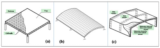
Figure 1.
Typical large-span Vierendeel roof system structures composed of a honeycomb sandwich structure: (a) plane; (b) curved surface; (c) gabled frame.
Initial investigations on this new structural system showed that [15,16] the failure mode of this prefabricated structure primarily takes the following form: (1) lateral pressure buckling failure on the internal surface of the honeycomb sandwich structure (Figure 2b, arrows) and (2) plate connector damage failure (Figure 2c, arrows). As internal force is transmitted among the honeycomb sandwich structures via a connector, the connector reliability determines the total stress-bearing capacity of this new structure system and has direct impact on its adoption and deployment in an actual project. Therefore, properly simulating connection performance among honeycomb sandwich structures is critical to a new structure’s reliability analysis and design. Similar to the lateral pressure performance that was investigated in a previous study [17], the connection performance of a honeycomb sandwich structure connector is an important technical issue that should be solved for this type of structure. The connection of mechanical properties—such as failure mode and ultimate bearing capacity—of a connector with different connection methods are aspects of this performance. Previously, McCarthy [18] has conducted a series of studies on the bolts and bolt-hole clearance. They have analyzed the impact of bolt-hole clearance on the load distribution and the extruding strength, which provided guidance for the specimen design in this paper. Matthews [19] has investigated the single bolt and multi bolts by experiments, from which they have found that the individual bolt will bear less load when the joint is more complex. Thus, the single bolt is adopted in experiment to guarantee that the connection fails first. Whitney and Nuismer [20] used the characteristic length method to calculate the connection strength. Chang [21] developed the characteristic length method to make it widely used in composite laminates structures. However, the existing literature lacks the studies of the connection performance of honeycomb sandwich structures, and the effect of sandwich wall thickness on the load bearing capacity has not been considered sufficiently. In order to investigate the connection performance of honeycomb sandwich structures that are connected via different methods, this paper has investigated the failure mode and connection performance of aluminium alloy honeycomb sandwich structures that are connected via three different methods, including a high-strength bolt, a low-cost ordinary bolt and a convenient self-tapping bolt. The connector’s bolt hole edge distance is optimized to reduce the connection plate dimensions and material consumption. Finite element analysis on the connector ultimate bearing capacity is performed for honeycomb sandwich structures with various thicknesses and bolt diameters to obtain a simplified formula for connector ultimate bearing capacity calculations for various failure modes via fitting. This formula provides a theoretical basis for the engineering design and application of a new honeycomb sandwich structure system.
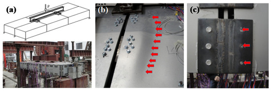
Figure 2.
Concatenation test for a honeycomb sandwich structure system: (a) Loading site; (b) Buckled shape of internal surface of the sandwich box; (c) Partially enlarged diagram of the lateral side of the box specimen: bolt is cut off.
2. Experimental Tests and Finite Element Simulations of Connector Performance
2.1. Experimental Tests
As current Chinese specifications have no detailed requirements for a connection performance test for a honeycomb sandwich structure, the specimen in this paper is designed and tested based on the connection test procedure in “Technical Specification for High Strength Bolt Connections of Steel Structures [22]” and “The Generals of Test Method for Properties of Adhesive-bonded Aluminium Honeycomb-Sandwich Structure and Core [23]”.
The planar dimensions of a concatenated honeycomb sandwich specimen are shown in Figure 3a. The plate thickness has three specifications: 10, 15, and 20 mm. The thicknesses of the top and bottom plates are 1 mm. The length and thickness of a regular hexagon honeycomb core’s side is 6 mm and 0.05 mm, respectively. The connectors include a high-strength bolt, an ordinary bolt, and a self-tapping bolt. Three specimens are made for each group with a total of 27 specimens. As the purpose of this study is to investigate a connector’s failure mode and failure mechanism [24,25,26,27,28], the connector failure prior to the plate material failure (connected matrix) should be avoided. Therefore, each side only contains a single bolt connection. The test is based on a displacement load method, which evenly applies tension to a specimen according to a specified load pattern at a continuous rate of 1 mm/min until failure occurs. As aluminium honeycomb core material is relatively soft, internal pads are attached at both ends to prevent the honeycomb core at both clamps from being flattened during loading and at the bolt connection point to avoid local pressure failure when a specimen is prepared.
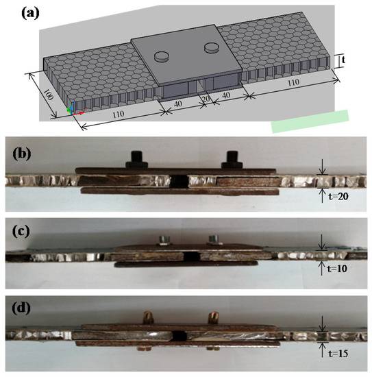
Figure 3.
Honeycomb sandwich specimens and connectors: (a) Specimen dimension and finite element model; (b) Self-tapping bolt; (c) Ordinary bolt; (d) High-strength bolt.
2.2. Finite Element Modeling and Analysis
ANSYS software is employed to create a corresponding honeycomb sandwich structure connector finite element model for the previously mentioned test specimen [29,30]. The honeycomb sandwich structure material properties are as follows: elastic modulus E = 70.0 GPa, shear modulus G = 27.0 GPa, yield stress σ0.2 =115.0 MPa, and ultimate stress σb = 165.0 MPa. Figure 4 shows the simplified constitutive relationships assumed for each part of the modeled specimen. The honeycomb core is modeled with shell elements while facesheets are modeled with solid elements [31,32,33]; core and facesheets are connected by contact elements [34,35]. As the model has symmetric geometrical dimensions, boundary constraint, and load, the analysis is based on a semi-structure, unidirectional, and uniform displacement load is applied to the end surface of the honeycomb sandwich structure at the slip end.
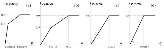
Figure 4.
Material constitutive relation: (a) Aluminium alloy honeycomb sandwich structure; (b) Connection plate; (c) High strength bolt; (d) Ordinary bolt and self-tapping bolt.
The results of previous research on a new honeycomb sandwich structure indicate that [16,17] the connector material accounts for more than 10% of this type of structure material. Hence, minimizing the dimensions of the connecting plate has a high economical value. However, this dimension is normally constrained by the bolt hole edge distance. In this paper, the connector model, which has dimensions that are identical to the dimensions of the specimen, is created. The bolt hole edge distances are set to 2.0, 1.5, 1.0, and 0.7d0 (d0 is the bolt hole diameter). The dimensions of the corresponding connection plate and pad are modified to perform a finite element analysis for the connector ultimate bearing capacity.
3. Results and Discussion
3.1. Analysis of Connector Failure Modes
Figure 5 shows the different failure modes observed for the connector in the experimental tests. The specimen has no distinct deformation under a relatively small tensile load. As the load gradually increases, the bolt will develop bending deformation. This process is accompanied by a distinct sound, which indicates that the honeycomb core is under pressure from facesheets and becomes partially flattened when the connector bears shear force (Figure 5d). When the load exceeds the bolt’s ultimate shear capacity, the bolt is cut off (Figure 5b,e) and a muffled sound is heard. The bolt hole in a honeycomb sandwich structure is also stretched to an oval shape under pressure, and the connector is damaged. As the high-strength bolt has a relatively high shear capacity, local tensile failure of the honeycomb sandwich structure occurs before some connectors reach their ultimate shear capacities. This failure causes the honeycomb sandwich structure to tear at the pad; however, the bolt is not cut off (Figure 5c).
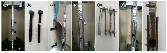
Figure 5.
Specimen failure process; (a–c) High strength bolt connector; (d,e) Ordinary bolt connector; (f,g) Self-tapping bolt connector.
Figure 6 shows the deformation and stress from the finite element analysis for the connector failure. As shown in Figure 6a,b, the total stress on the honeycomb sandwich structure is relatively high; the honeycomb core and the honeycomb facesheets, pad, and connection plate have relatively small displacements; the displacement at the opening suddenly increases; the bolt develops bending deformation under load. The total stress on the honeycomb sandwich structure is primarily less than 260 MPa. However, severe stress concentration occurs at the contact points among the opening, bolt, and connection plate.
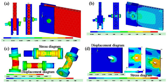
Figure 6.
Results of FE simulations: (a,b) displacement field and stress distribution for the sandwich structure; (c) displacement field and stress distribution for the high-strength bolt; (d) displacement field and stress distribution for the connection plate. Displacements are expressed in mm and stress in MPa.
Figure 6c,d show displacement and stress distributions of the bolt and connection plate in the entity model for the honeycomb sandwich structure connector. The bolt develops tiny bending deformation and rigid rotation; the displacement in the central part of the bolt is relatively large (Figure 6c). A stress concentration occurs at the contact point with the pad, the maximum stress is 780 MPa, the working stress exceeds 22% of the ultimate strength—in order to intuitively and precisely find the failure position of high strength bolt, we intentionally did not set it in the finite element analysis, and observed the stress concentration degree—and material yield occurs. The bolt develops bending deformation and exerts pressure on the connection plate, and the stress in this area is relatively high. The total connection plate displacement is relatively small, and the bolt hole develops significant deformation. A stress concentration occurs at the honeycomb sandwich structure’s contact point with the connection plate, and the maximum stress is 270 MPa. The stress around the bolt hole exceeds the material yield stress, which causes the surrounding yielding bolt hole to become stretched into an oval shape (Figure 6d).
3.2. Load-Displacement Curves for Different Connectors
Figure 7 shows the load-displacement curves for honeycomb sandwich structures of different thicknesses, connected by various methods. It can be seen that each connection method has its peculiar performance and failure modes. At the initial stage of loading, all connectors have almost the same rigidity and load increases for larger end surface displacement. As a high-strength bolt material has superior shear strength [36,37], the ultimate bearing capability of the corresponding connector is significantly higher than the ultimate bearing capability of the other two connection methods; it also has larger ultimate displacement. The ordinary bolt connection and self-tapping bolt connector have similar ultimate bearing capacities. When the self-tapping bolt connector approaches the limit, its bearing capacity fluctuates and the connection performance is unstable.
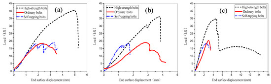
Figure 7.
Comparison of load-displacement curves obtained experimentally for the different types of connectors for (a) 10 mm, (b) 15 mm, and (c) 20 mm wall thickness.
Figure 8 compares the load-displacement curves measured from experiments and the corresponding finite element simulations for the three bolt joints designs. It can be seen that numerical results agree well with experimental data: the largest deviation is less than 3.6%.
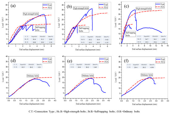
Figure 8.
Comparison of experimental tests and FE simulations for the load-displacement curves relative to different bolt connections and sandwich wall thicknesses. (a–c) High strength bolts and self-tapping bolts; (d–f) Ordinary bolts.
Since finite element analysis implemented simplified constitutive models, the simulated load-displacement curves show a distinct yielding point and strengthening phase. However, experimental and numerical load-displacement curves have identical growth trends.
When a high-strength bolt connector is subject to shear loading, severe stress concentration develops in the bolt causing bending deformations. The connection plate opening is substantially damaged and the bolt hole is ovalized. Because of the relatively low shear strength of an ordinary bolt connector, the connection plate and pad under shear force will not develop significant deformation. A significant stress concentration occurs at the bolt shear surface, and significant shear deformation causes bolt failure. As the self-tapping bolt connector’s screw thread has relatively weak mechanical bite force, the bolt under load develops significant deflection and bending deformation, which causes conspicuous warp deformation between a connection plate and honeycomb sandwich structure (Figure 5f,g).
3.3. Optimization of Connector Geometry and Determination of Ultimate Bearing Capacity
3.3.1. Connector Geometry Optimization: Sensitivity of Connector Performance to Bolt Hole-Edge Distance
Figure 9a shows the load-displacement curves computed via FEA for models with various hole-edge distances. It can be seen that curves are very similar if the hole-edge distance is between 1.0d0 and 1.5d0. For the very small hole-edge distance of 0.7d0, the significantly lighter honeycomb sandwich structure and pad section host very high stresses. The stress in the bolt hole section ranges between 522 and 590 MPa, which exceeds the common yield strength of aluminum alloys and produces damage in the connection plate.
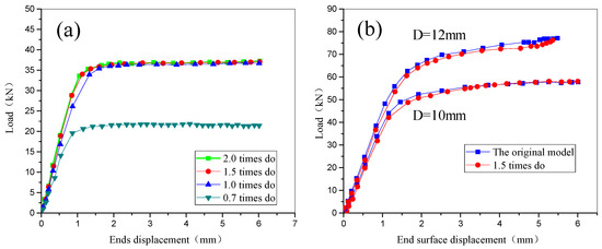
Figure 9.
Load-displacement curves determined by ANSYS for (a) models with different hole-edge distances; (b) models with different bolt diameters.
The ultimate load is about 36 kN for all connectors with hole-edge distances greater or equal to 1.0d0 but drops down to 21.64 kN (i.e., 40% reduction in shear load bearing capacity) for the hole-edge distance of 0.7d0.
Based on these results, we modified the geometry of the high-strength bolt connector setting the hole-edge distance equal to 1.5d0. Load-displacement curves of optimized models including different values of the bolt diameter are compared with those relative to the original design. Figure 9b shows that, regardless of bolt diameter, a hole-edge distance of 1.5d0 allows to reach the same performance as for the original design. In summary, the minimum dimensions of the connection plate and pad can be optimized to be 1.5 times the bolt hole diameter to ensure that the connector has sufficient bearing capacity yet reducing connector material consumption.
3.3.2. Simplified Formula for Computing the Connector Ultimate Bearing Capacity
A new formula was developed in this study to predict the ultimate shear strength of bolt connectors for sandwich structures. For that purpose, the hole diameter and sandwich wall thickness were modified in the finite element analysis. Figure 10 shows the variation of the connector’s ultimate load (P) with respect to bolt diameter (d) and sandwich wall thickness [38] (t). Shear load capacity is insensitive to diameter if the bolt diameter remains relatively small. In this case, bolt shear failure is the dominant mechanism and the overall performance of the connector basically depends on the bolt diameter. When bolt diameter increases beyond 10 mm, strength becomes sensitive to the thickness of the sandwich structure. In particular, larger thickness results in a higher connection strength but also in more significant bolt hole deformation. The failure mode changes from bolt cut-off damage to hole wall bearing failure. In summary, connector strength varies with bolt diameter and sandwich wall thickness based on the hole diameter. In view of this, two simple formulae were derived by fitting results of FE simulations.
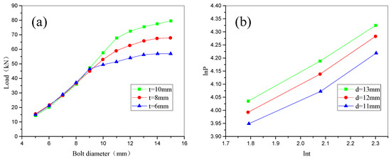
Figure 10.
Variation of connector’s shear load capability with respect to (a) bolt diameter and (b) sandwich wall thicknesses. (lnt = loge(t), lnP = loge(P)).
(1) For high-strength bolt shear failure, the ultimate bearing capacity of the connector is determined as
(The corresponding formula available in the current Chinese Steel Structure Design Specification is )
(2) For bolt hole wall bearing failure, the ultimate bearing capacity of the connector is determined as
(The corresponding formula available in the current Chinese Steel Structure Design Specification is ) where and are the shear ultimate strength and compression ultimate strength of the high-strength bolt or connection plate material, respectively; t is the thickness of the honeycomb sandwich structure; d is the bolt diameter.
The new derivation from this work yields similar results as the existing Chinese [22], American, and European Steel Structure Design Specifications [38] when bolt shear failure occurs. Under such scenarios, the ultimate strength of the connector is proportional to the bolt shear bearing area. Since all the specifications are mainly applied for steel plates and do not consider the effect of sandwich wall thickness on the load bearing capacity, they are more conservative than the present approach. When bolt hole wall bearing failure occurs, the present formula significantly differs from the previous standards. ANSYS results indicate that bolt opening deforms and significant displacement occurs at the bolt shear surface; hence, the connector does not develop hole wall bearing failure. It indicates that steel structure design specifications cannot be applied to the honeycomb sandwich structures. Therefore, the fitting formula from the finite-element analysis and test results are more suitable for the connection of honeycomb sandwich structures than the existing standards.
4. Conclusions
This study analyzed the performance of bolt connectors for honeycomb sandwich plates. Different connector designs were compared by carrying out experimental tests and finite element simulation. The main findings of the study can be summarized as follows:
- (1)
- The failure of a high strength bolt connector is driven by severe stress concentration and minor bending deformation of the bolt. Connection plate and pad openings are ovalized and the excessive total displacement causes the failure of the joint. The ordinary bolt connector fails because stress concentration on bolt shear surface causes excessive deformation. Self-tapping bolt connector failure mechanisms are intermediate between those observed for high-strength and self-tapping bolt connectors. The high-strength bolt connector has the highest shear capacity followed by ordinary bolt and self-tapping bolt connectors. Hence, high strength connectors are preferred although ordinary bolts also may be utilized.
- (2)
- Finite element simulations are in agreement with experimental data of load-displacement curves that were reproduced with less than 3.6% difference in terms of load-displacement curves. The present model can hence turn useful in designing new connection systems for aluminum sandwich structures. The geometry of the connector was optimized by setting the bolt hole-edge distance equal to 1.5 times the bolt diameter.
- (3)
- Numerical results validated by experimental data were fitted to obtain a very simple formula that predicts the connector’s ultimate shear load bearing capacity. The new approach is less conservative than Chinese standards as it accounts for the contribution of the sandwich wall thickness to shear load capacity. This may be the starting point for future revisions of design specifications that should be used for a new honeycomb sandwich structural system.
Acknowledgments
This study was supported by the Natural Science Foundation of China under Grant No. 51578136.
Author Contributions
Caiqi Zhao and Weidong Zheng conceived and designed the experiments; Weidong Zheng performed the experiments; Jun Ma and Yangjian Zhao analyzed the data; Jun Ma and Caiqi Zhao contributed reagents/materials/analysis tools; Caiqi Zhao wrote the paper.
Conflicts of Interest
The authors declare no conflict of interest.
References
- Ma, Y.X.; Zheng, Y.D.; Meng, H.Y.; Song, W.H.; Yao, X.F.; Lv, H.X. Heterogeneous PVA hydrogels with micro-cells of both positive and negative Poisson's ratios. J. Mech. Behav. Biomed. Mater. 2013, 23, 22–31. [Google Scholar] [CrossRef] [PubMed]
- Dirks, J.-H.; Dürr, V. Biomechanics of the stick insect antenna: Damping properties and structural correlates of the cuticle. J. Mech. Behav. Biomed. Mater. 2011, 4, 2031–2042. [Google Scholar] [CrossRef] [PubMed]
- Koester, K.J.; Barth, H.D.; Ritchie, R.O. Effect of aging on the transverse toughness of human cortical bone: Evaluation by R-curves. J. Mech. Behav. Biomed. Mater. 2011, 4, 1504–1513. [Google Scholar] [CrossRef] [PubMed]
- Donius, A.E.; Liu, A.; Berglund, L.A.; Ulrike, G.K. Wegst Superior mechanical performance of highly porous, anisotropic nanocellulose–montmorillonite aerogels prepared by freeze casting. J. Mech. Behav. Biomed. Mater. 2014, 37, 88–99. [Google Scholar]
- Tuo, W.Y.; Chen, J.X.; Wu, Z.S.; Xie, J.; Wang, Y. Characteristics of the tensile mechanical properties of fresh and dry forewings of beetles. Mater. Sci. Eng. C 2016, 65, 51–58. [Google Scholar] [CrossRef] [PubMed]
- Chen, J.X.; Zu, Q.; Wu, G.; Xie, J. Review of beetle forewing structure and biomimetic applications in China(II). Mater. Sci. Eng. C 2015, 50, 620–633. [Google Scholar] [CrossRef] [PubMed]
- Chen, J.X.; Gu, C.; Guo, S.; Wan, C.; Wang, X.; Xie, J.; Hu, X. Integrated honeycomb technology motivated by the structure of beetle forewings. Mater. Sci. Eng. C 2012, 32, 1813–1817. [Google Scholar] [CrossRef]
- Zhang, X.M.; Liu, C.; Chen, J.X.; Tao, Y.; Gu, Y. The influence mechanism of processing holes on the flexural properties of biomimetic integrated honeycomb plates. Mater. Sci. Eng. C 2016, 6, 798–803. [Google Scholar] [CrossRef] [PubMed]
- Chen, J.X.; He, C.L.; Gu, C.L.; Liu, J.X.; Mi, C.W.; Guo, J.S. Compressive and flexural properties biomimetic integrated honeycomb plates. Mater. Des. 2014, 64, 214–220. [Google Scholar] [CrossRef]
- Chen, J.X.; Tuo, W.Y.; Zhang, X.M.; He, C.L.; Xie, J.; Liu, C. Compressive failure modes and parameter optimization of the trabecular structure of biomimetic fully integrated honeycomb plates. Mater. Sci. Eng. C 2016, 69, 255–261. [Google Scholar] [CrossRef] [PubMed]
- Bourada, M.; Tounsi, A.; Houari, M.S.A.; Adda Bedia, E.A. A new four-variable refined plate theory for thermal buckling analysis of functionally graded sandwich plates. J. Sand. Struct. Mater. 2011, 14, 5–33. [Google Scholar] [CrossRef]
- Zyniszewski, S.S.; Smith, B.H.; Hajjar, J.F.; Arwade, S.R.; Schafer, B.W. Local buckling strength of steel foam sandwich panels. Thin-Walled Struct. 2012, 59, 11–19. [Google Scholar] [CrossRef]
- Boudjemai, A.; Amri, R.; Mankour, A.; Salem, H.; Bouanane, M.H.; Boutchicha, D. Modal Analysis and Testing of Hexagonal Honeycomb Plates Used for Satellite Structural Design. Mater. Des. 2012, 35, 266–275. [Google Scholar] [CrossRef]
- Zhao, C.Q.; Ma, J. Assembled Honeycombed Sheet Light Empty Stomach Building and Roof Structure System. Patent Application No. 200810100745.X; Publication No. CN101270595A, 21 April 2010. [Google Scholar]
- Zhao, C.Q.; Ma, J.; Tao, J. Experimental study on load capacity of new fabricated honeycomb panel open-web roof structures. J. Southeast Univ. (Nat. Sci. Ed.) 2014, 44, 626–630. [Google Scholar]
- Tao, J. Experimental Study on Lightweighted Roof Structures Based on Honeycomb Panel in High Performance. Master’s Thesis, School of Civil Engineering of Southeast University, Nanjing, China, 2012. [Google Scholar]
- Zhao, C.Q.; Zheng, W.D.; Ma, J.; Zhao, Y.J. Lateral compressive buckling performance of aluminum honeycomb panels for long-span hollow core roofs. Materials 2016, 9, 444. [Google Scholar] [CrossRef]
- Mccarthy, M.A.; Mccarthy, C.T.; Padhi, G.S. A simple method for determining the effects of bolt–hole clearance on load distribution in single-column multi-bolt composite joints. Compos. Struct. 2006, 73, 78–87. [Google Scholar] [CrossRef]
- Quinn, W.J.; Matthews, F.L. The Effect of Stacking Sequence on the Pin-Bearing Strength in Glass Fibre Reinforced Plastic. J. Compos. Mater. 1977, 11, 139–145. [Google Scholar] [CrossRef]
- Whitney, J.M.; Nuismer, R.J. Stress Fracture Criteria for Laminated Composites Containing Stress Concentrations. J. Compos. Mater. 1974, 8, 253–265. [Google Scholar] [CrossRef]
- Chang, F.K.; Scott, R.A.; Springer, G.S. Failure of Composite Laminates Containing Pin Loaded Holes—Method of Solution. J. Compos. Mater. 1984, 18, 255–278. [Google Scholar] [CrossRef]
- Industry Standard of the People’s Republic of China JGJ82-2011. In Technical Specification for High Strength Bolt Connections of Steel Structures; Ministry of Housing and Urban Rural Development of the People’s Republic of China: Beijing, China, 2011.
- Standardization Administration of China GJB130.1-86. In The Generals of Test Method for Properties of Adhesive-Bonded Aluminum Honeycomb-Sandwich Structure and Core; Standard Press of China: Beijing, China, 1986.
- Kim, T.S.; Yoo, J.H.; Roeder, C.W. Experimental investigation on strength and curling influence of bolted connections in thin-walled carbon steel. Thin-Walled Struct. 2015, 91, 1–12. [Google Scholar] [CrossRef]
- Ma, H.-H.; Issa, A.M.; Fan, F.; Adeoti, G.O. An experimental and numerical study of a semi-rigid bolted-plate connections (B.P.C.). Thin-Walled Struct. 2015, 88, 82–89. [Google Scholar] [CrossRef]
- Yu, C.; Panyanouvong, M.X. Bearing strength of cold-formed steel bolted connections with a gap. Thin-Walled Struct. 2013, 67, 110–115. [Google Scholar] [CrossRef]
- Jam, J.E.; Ghaziani, N.O. Numerical and experimental investigation of bolted joints, International. J. Eng. Sci. Technol. 2011, 3, 285–296. [Google Scholar]
- Satasivam, S.; Bai, Y. Mechanical performance of bolted modular GFRP composite sandwich structures using standard and blind bolts. Compos. Struct. 2014, 117, 59–70. [Google Scholar] [CrossRef]
- Kim, T.S.; Kuwamura, H.; Kim, S.; Lee, Y.T.; Cho, T. Investigation on ultimate strength of thin-walled steel single shear bolted connections with two bolts using finite element analysis. Thin-Walled Struct. 2009, 47, 1191–1202. [Google Scholar] [CrossRef]
- Kim, T.S.; Kuwamura, H. Finite element modeling of bolted connections in thin-walled stainless steel plates under static shear. Thin-Walled Struct. 2007, 45, 407–421. [Google Scholar] [CrossRef]
- Fallahnezhad, K. Andrew Steele and Reza H. Oskouei, Failure mode analysis of aluminium alloy 2024-T3 in double-lap bolted joints with single and double fasteners; A Numerical and Experimental Study. Materials 2015, 8, 3195–3209. [Google Scholar] [CrossRef]
- Rezaeifard, M.; Salami, S.J.; Dehkordi, M.B.; Sadighi, M. A new nonlinear model for studying a sandwich panel with thin composite faces and elastic–plastic core. Thin-Walled Struct. 2016, 107, 119–137. [Google Scholar] [CrossRef]
- Mallela, U.K.; Upadhyay, A. Buckling load prediction of laminated composite stiffened panels subjected to in-plane shear using artificial neural networks. Thin-Walled Struct. 2016, 102, 158–164. [Google Scholar] [CrossRef]
- Hassanli, S.; Samali, B. Buckling analysis of laminated composite curved panels reinforced with linear and non-linear distribution of Shape Memory Alloys. Thin-Walled Struct. 2016, 106, 9–17. [Google Scholar] [CrossRef]
- Khandelwal, R.P.; Chakrabarti, A.; Bhargava, P. Effect of interfacial imperfection on bending behavior of composites and sandwich laminates by an efficient C0 FE model. Thin-Walled Struct. 2014, 82, 170–182. [Google Scholar] [CrossRef]
- Cai, Y.C.; Young, B. Bearing factors of cold-formed stainless steel double shear bolted connections at elevated temperatures. Thin-Walled Struct. 2016, 98, 212–229. [Google Scholar] [CrossRef]
- Cho, Y.H.; Kim, T.S. Estimation of ultimate strength in single shear bolted connections with aluminum alloys (6061-T6). Thin-Walled Struct. 2016, 101, 43–57. [Google Scholar] [CrossRef]
- Pan, B.; Shi, Y.; Wang, Y. The Effect of Yield-to-ultimate Ratio on the Bolted Connection under Static Shear. J. Shenyang Jianzhu Univ. 2012, 28, 501–506. [Google Scholar]
© 2017 by the authors. Licensee MDPI, Basel, Switzerland. This article is an open access article distributed under the terms and conditions of the Creative Commons Attribution (CC BY) license (http://creativecommons.org/licenses/by/4.0/).