
A New High-Efficiency Double-Stator Split-Pole Permanent-Magnet Vernier Machine with Flux-Focusing Topology

Abstract
:
1. Introduction
2. Machine Design
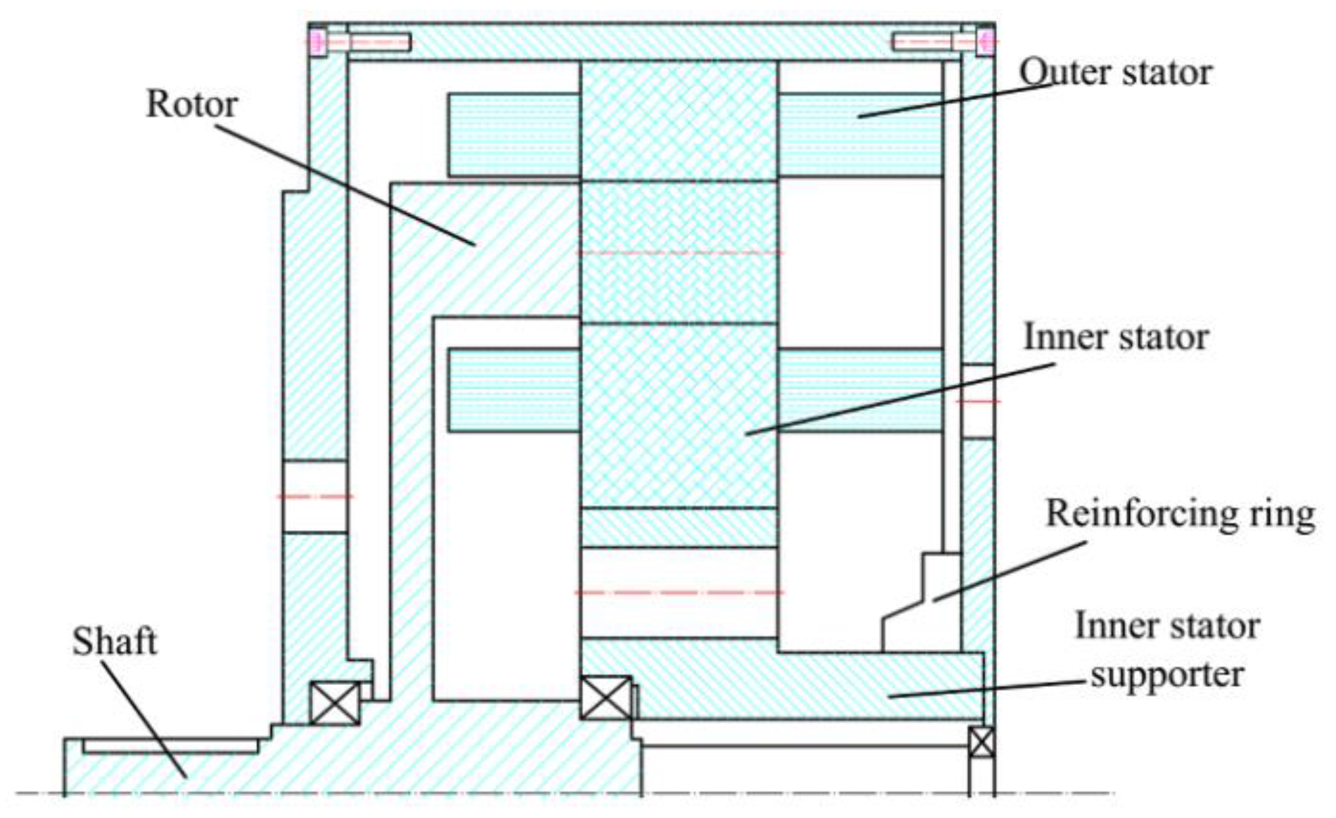
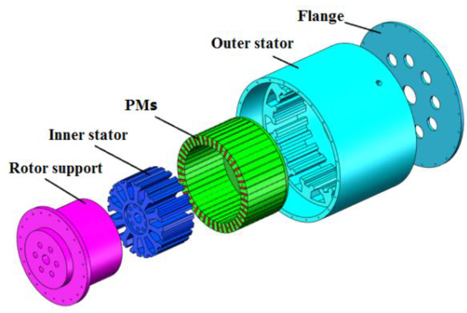
2.1. Mechanical Design
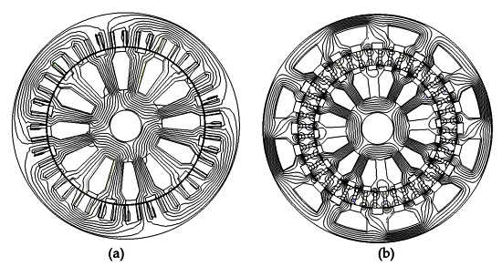
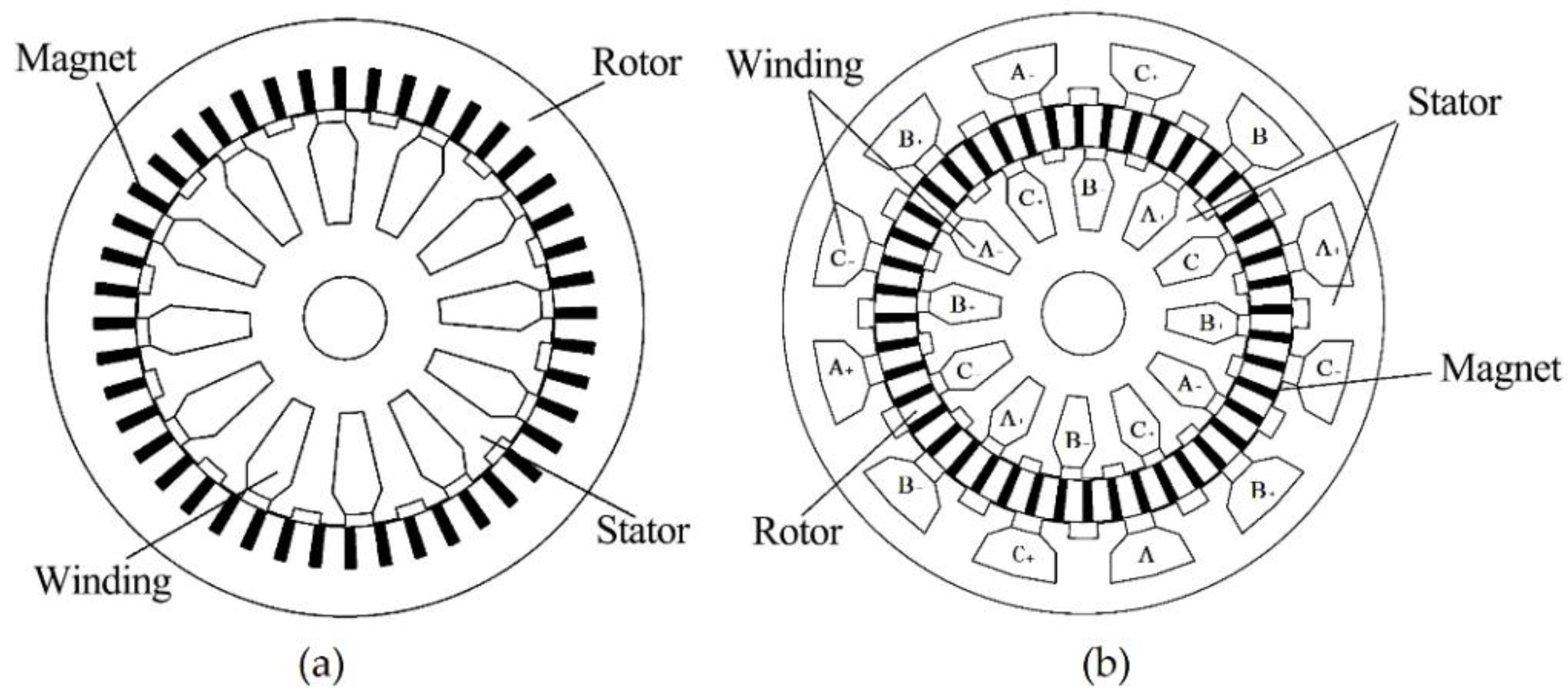
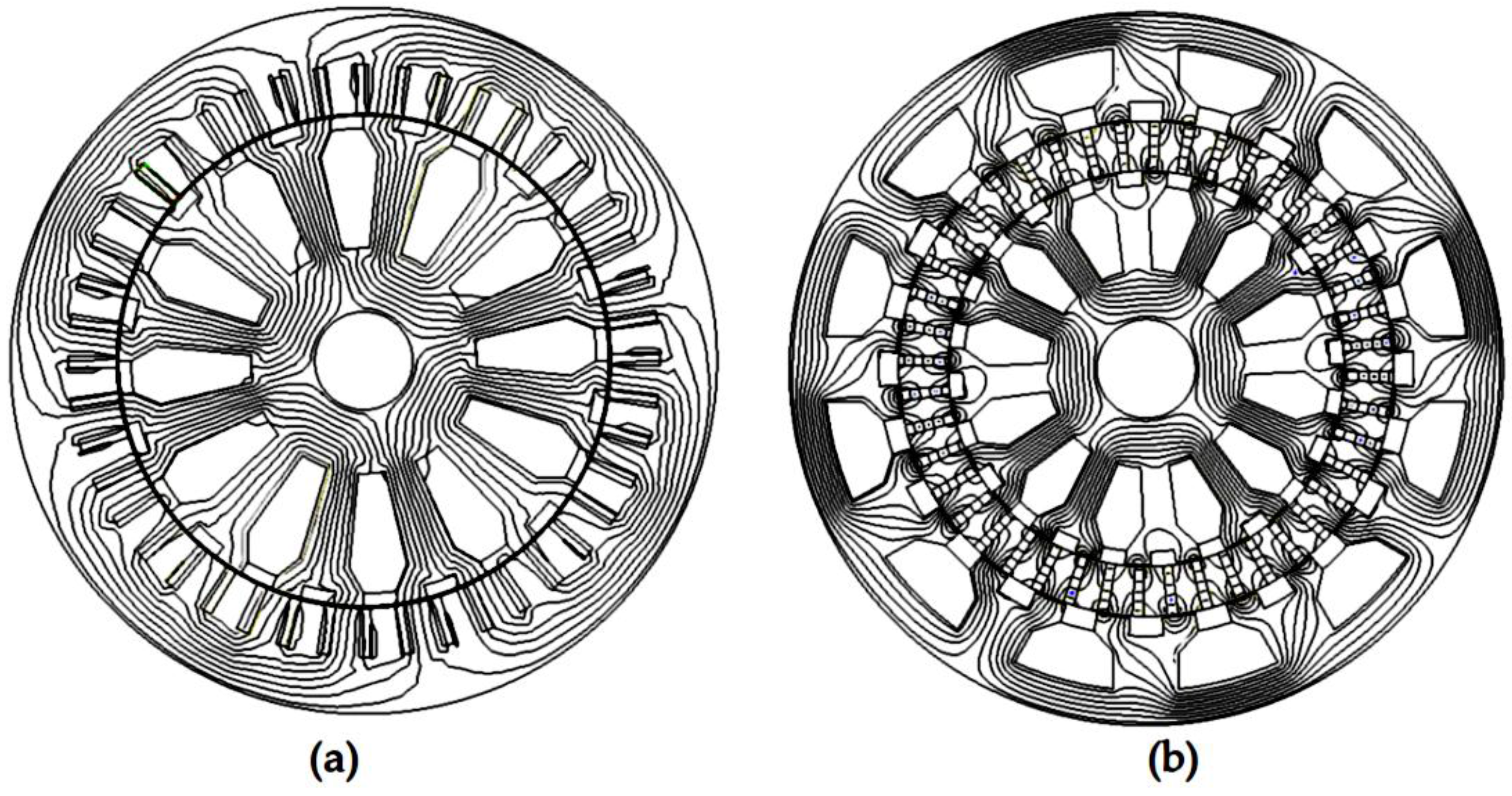
2.2. Machine Topology
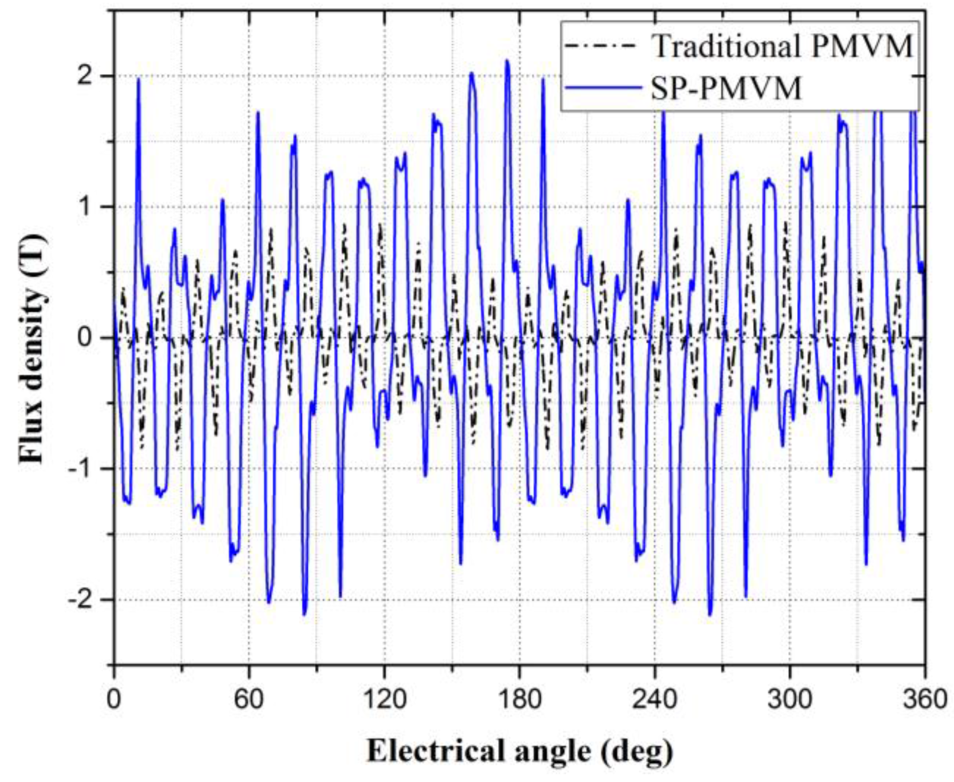
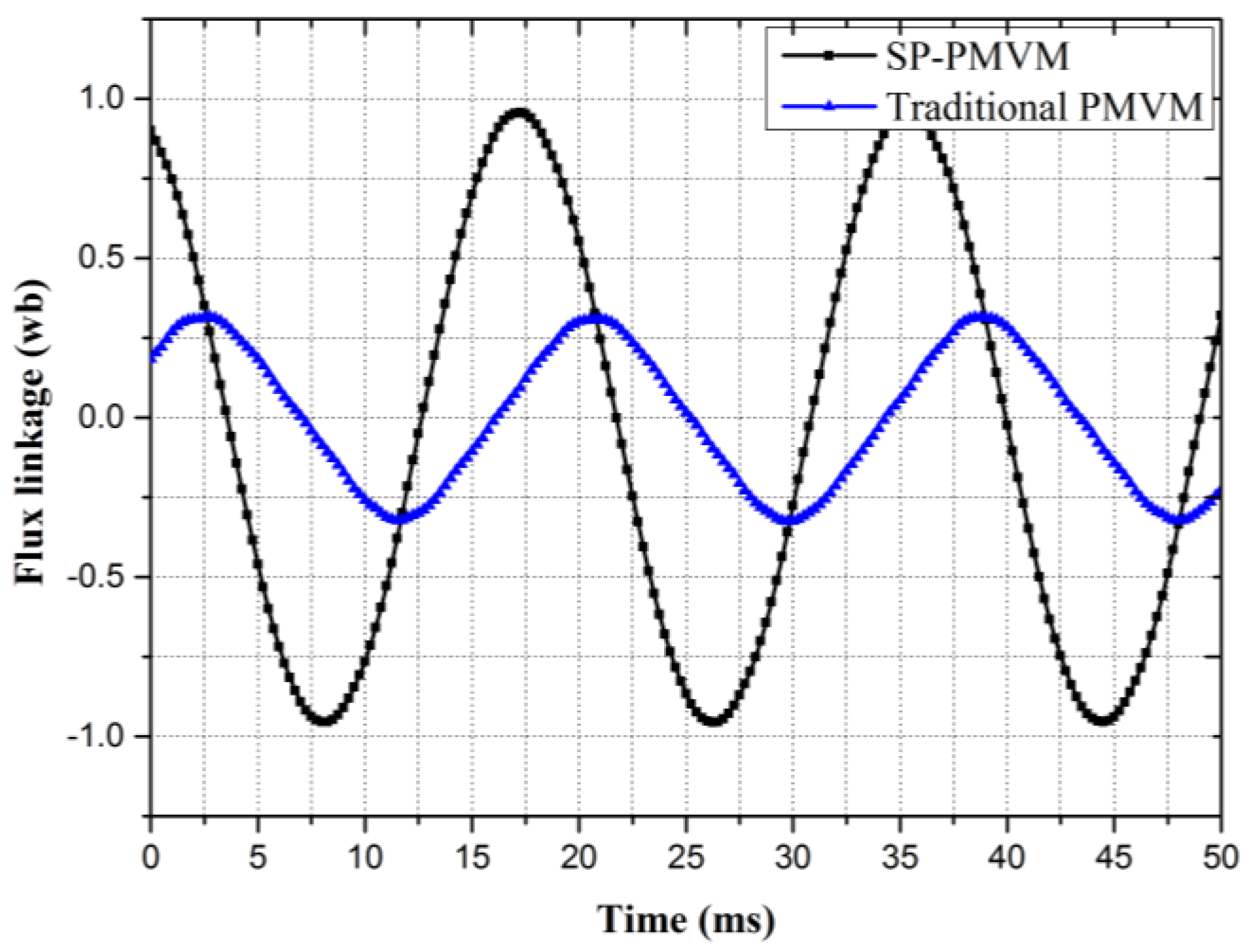
3. Theoretical Analysis
4. Premise for Fair Comparison
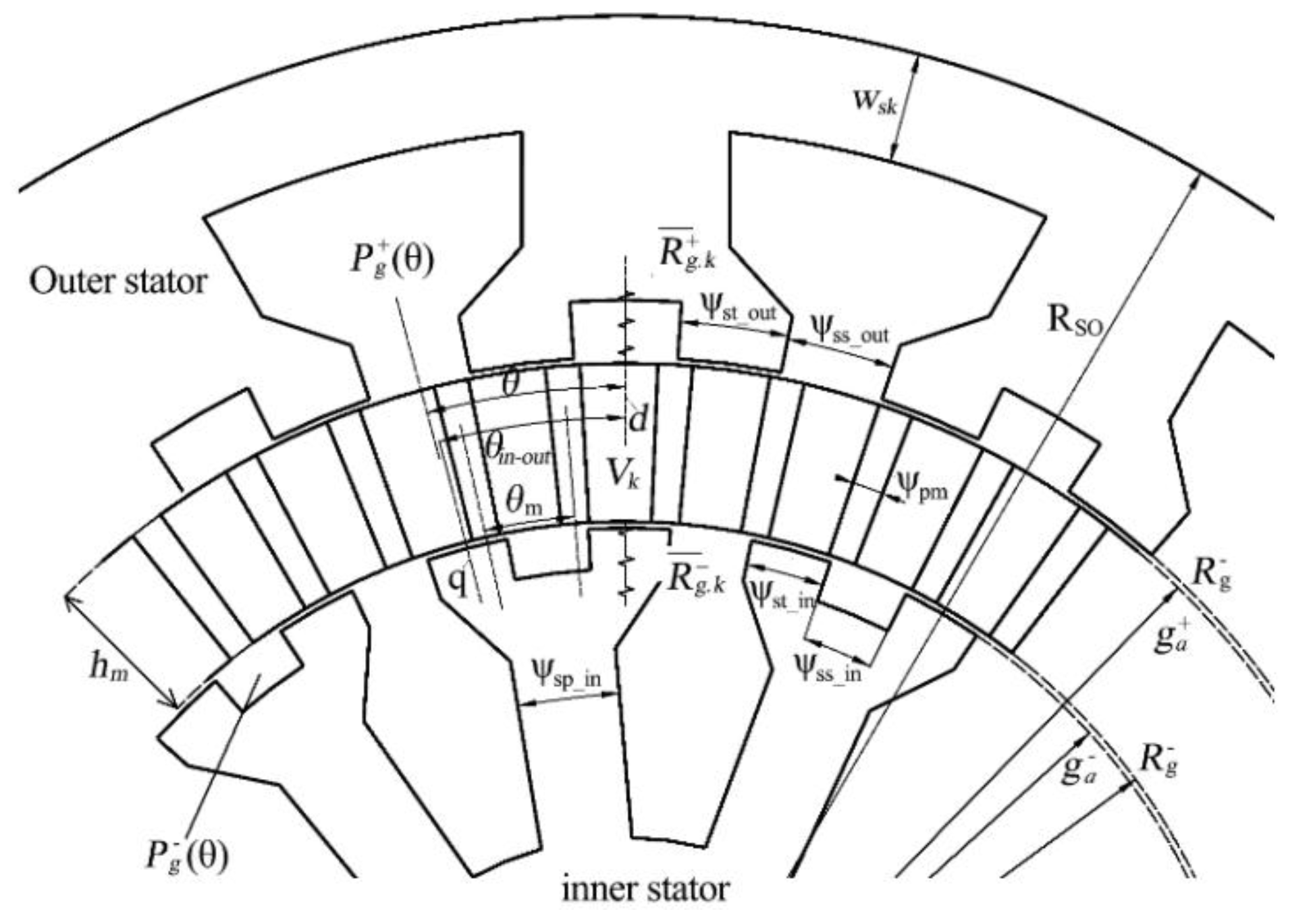
- Some original dimensions and parameters should be defined and explained. ψss_in and ψss_out are the pole-arc to pole-pitch ratios of the inner and outer stators, respectively; ψst_in and ψst_out are the stator tooth width of the inner and outer stators, respectively. The ψpm is the rotor PM width in degrees, and these parameters are used to define the coefficients:where .
- The βs is the original rotor module tooth width, which satisfies:
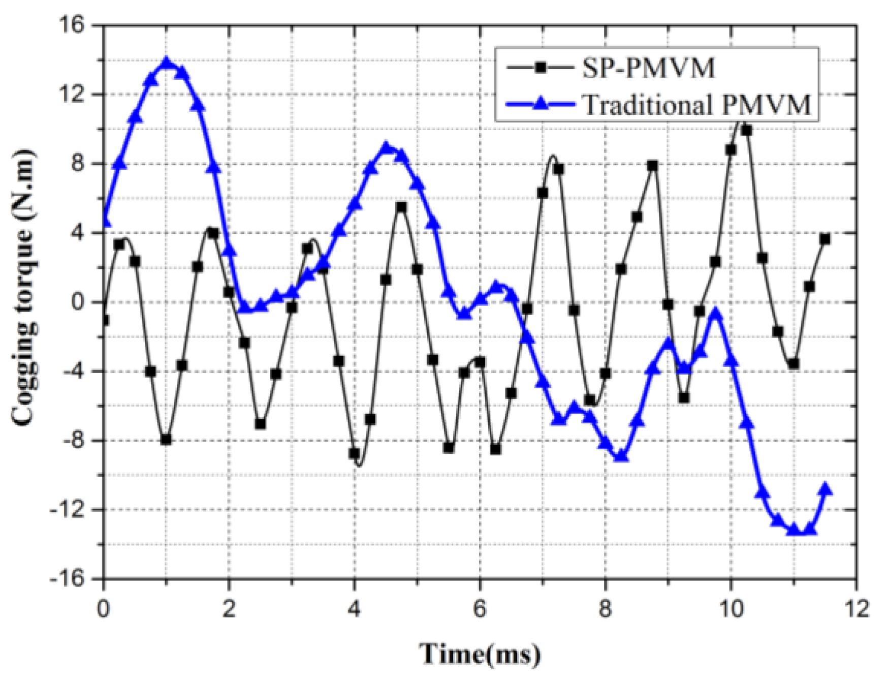
- In addition, to analysis the cogging torque, the rotor speed is set as 1 rpm and all armature winding current are set as zero [13].
5. Optimization of SP-PMVM
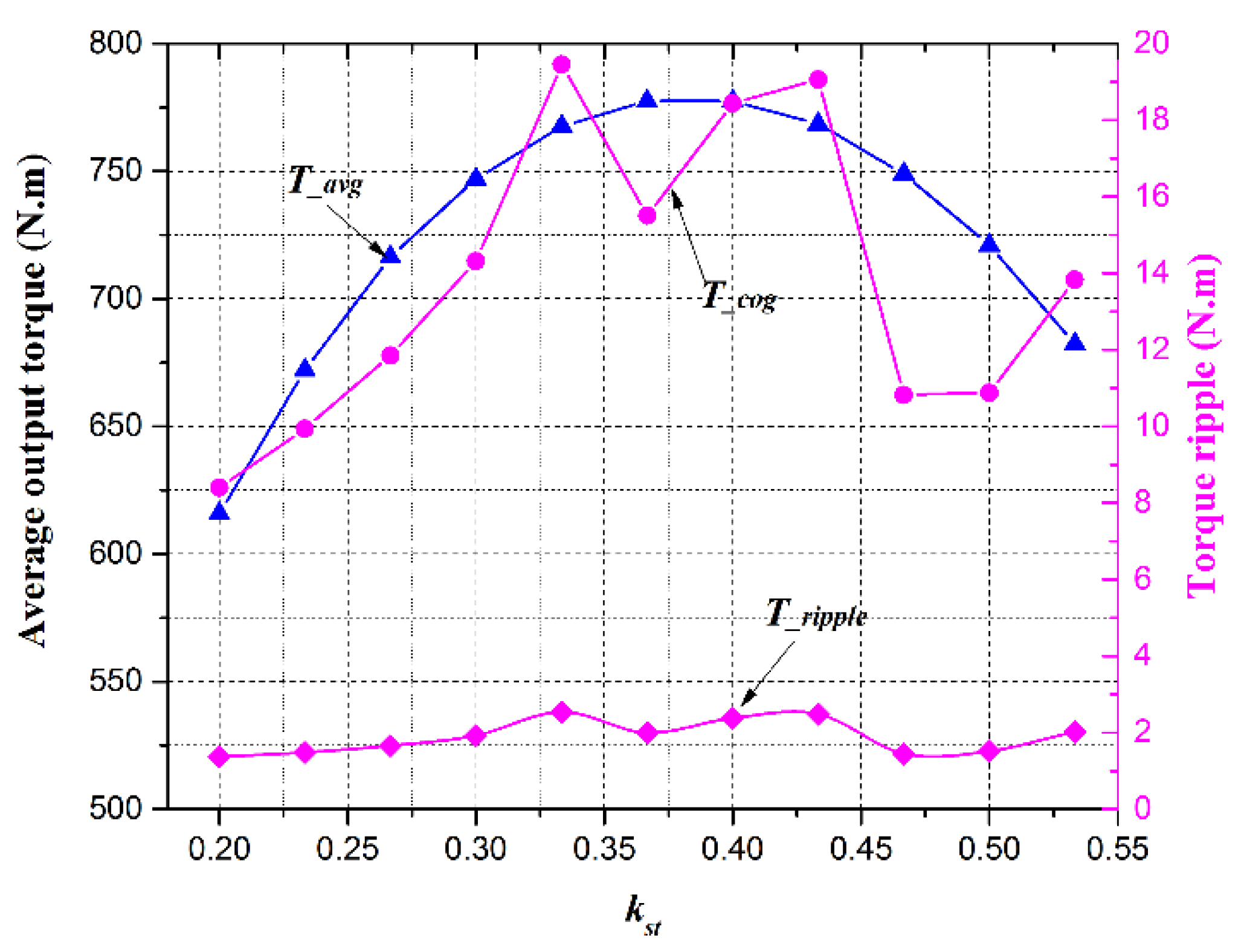
5.1. Optimize kst
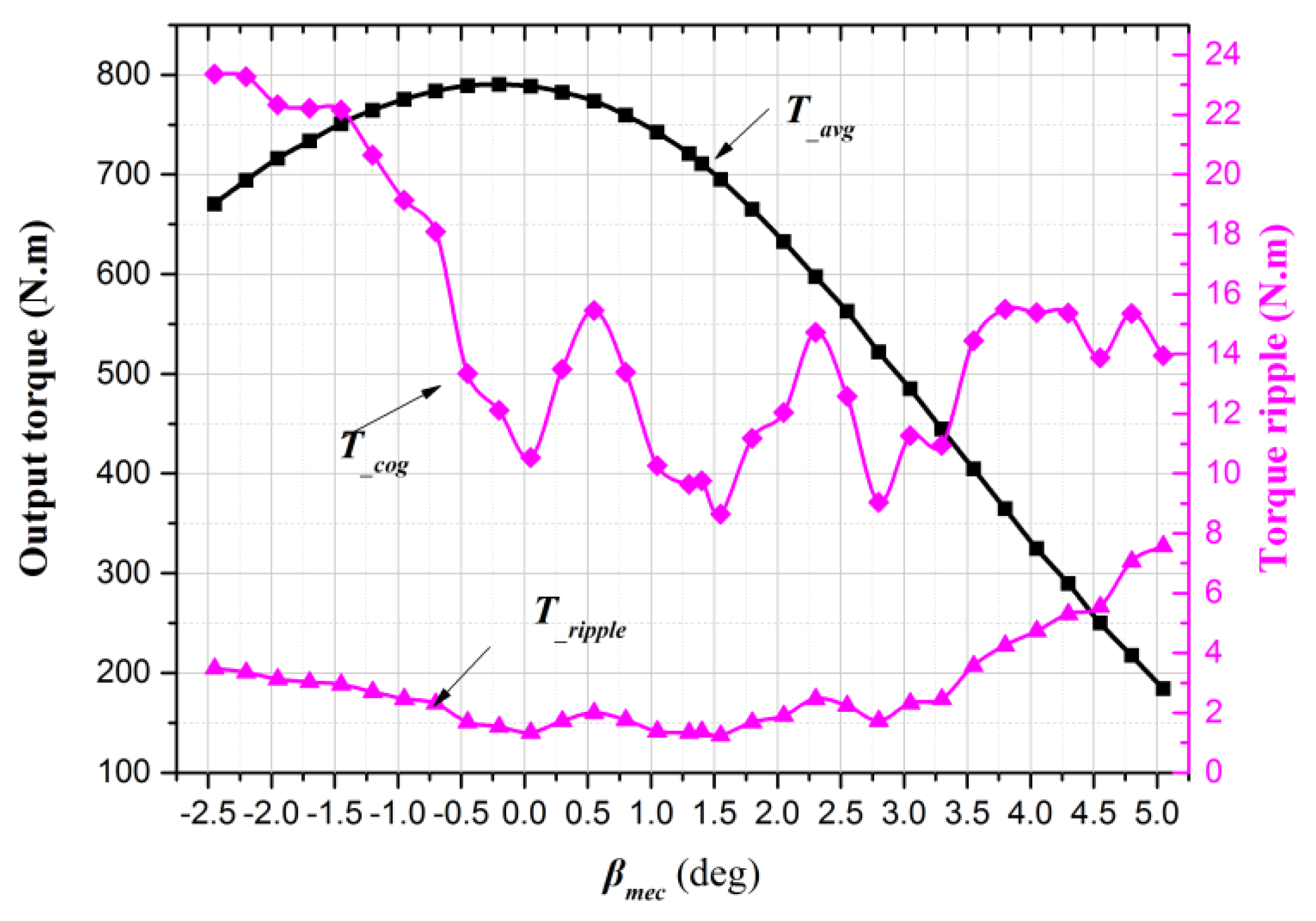
5.2. Optimize βmec
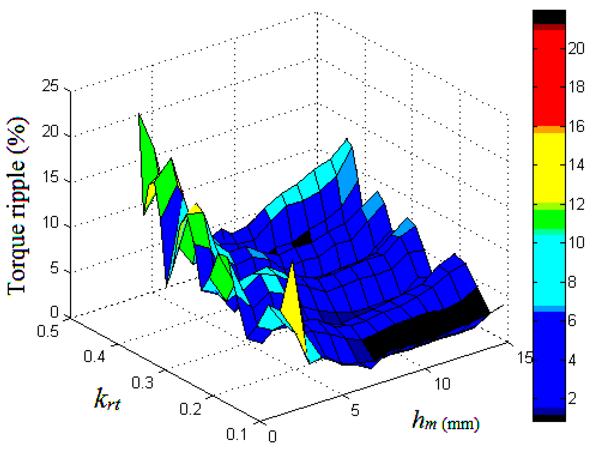
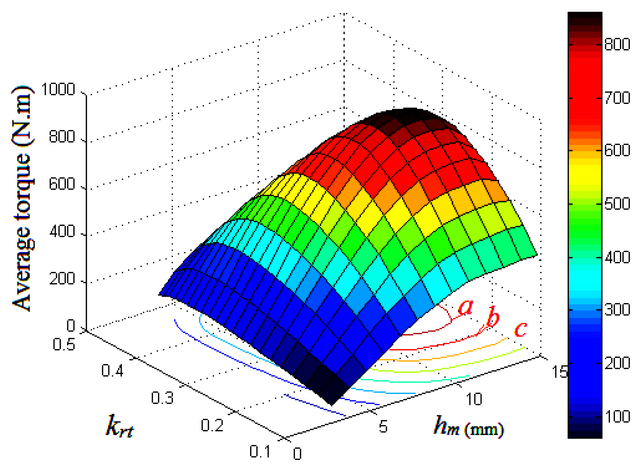
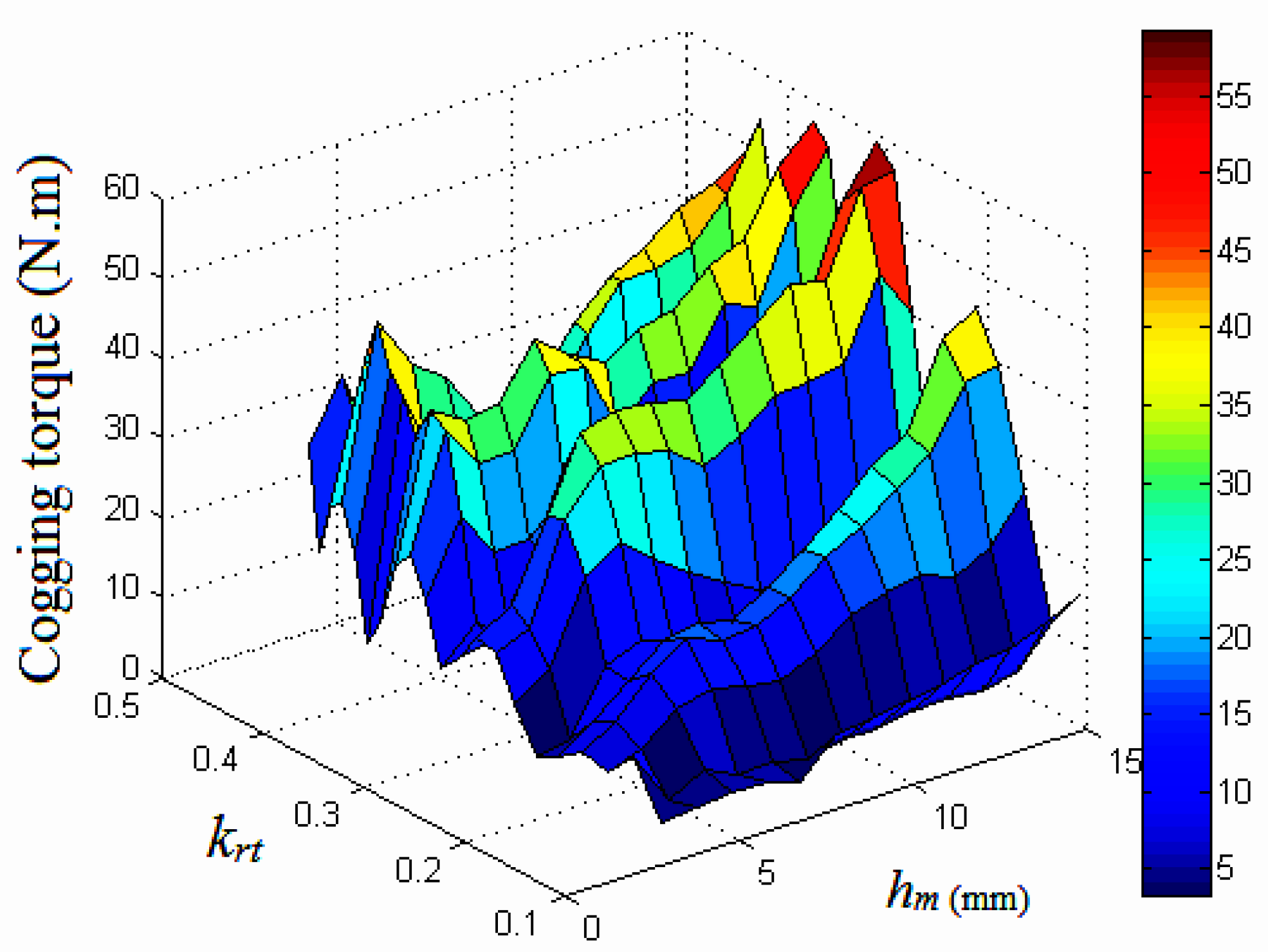
5.3. Optimize krt and hm
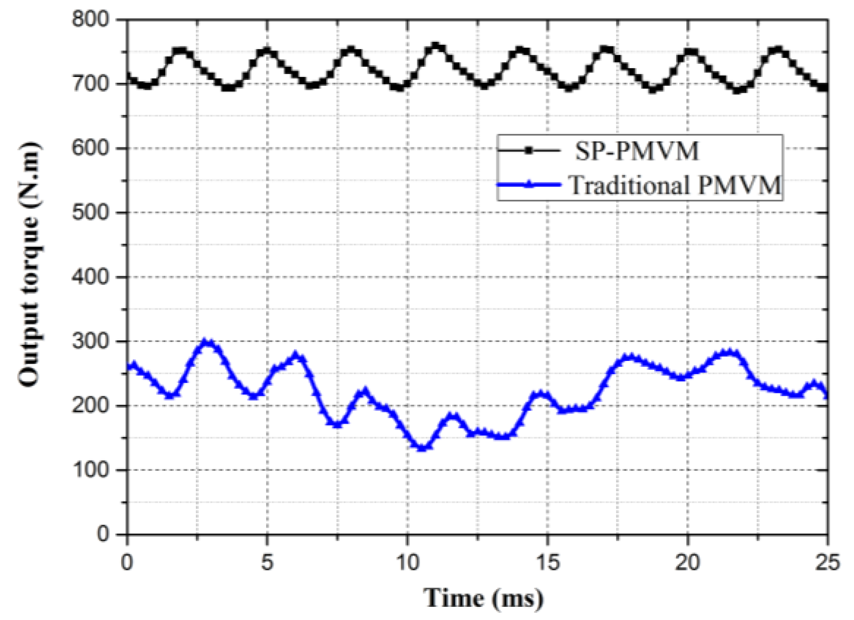
6. Performance Comparison
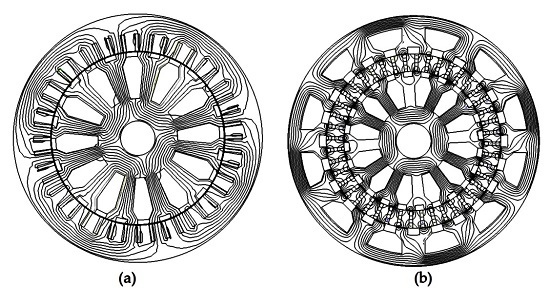
- The SP-PMVM has two air gaps instead of one; therefore, the active area of the machine is almost doubled.
- Comparing with the conventional PMVM with a low power factor (about 0.3–0.6 [8]), the SP-PMVM topology can improve the power factor significantly by staggering about half of the pitch angularly between the inner stator and outer stator.
- Comparing with the conventional PMVM, the magnetic flux leakage of the SP-PMVM has been reduced significantly.
7. Conclusions
- The torque-handling ability is improved by 240%. The output torque per kg PM of the SP-PMVM is about 2.4 times of that of the conventional PMVM.
- The power factor, which is one of the most significant problems of PMVM, has been improved from about 0.4 to 0.87. For the same current, the SP-PMVM has a lower requirement on the battery for electric drive vehicles (EDVs).
- The torque ripple is induced from 12.7% to 1.31%. This may broaden the potential application area of the SP-PMVM.
Acknowledgments
Author Contributions
Conflicts of Interest
References
- Gu, C.Y.; Zhao, W.X.; Zhang, B.F. Simplified minimum copper loss remedial control of a five-phase fault-tolerant permanent-magnet vernier machine under short-circuit fault. Energies 2016, 9, 860. [Google Scholar] [CrossRef]
- Yang, H.; Lin, H.Y; Zhu, Z.Q.; Fang, S.H.; Huang, Y.K. A dual-consequent-pole vernier memory machine. Energies 2016, 9, 134. [Google Scholar] [CrossRef]
- Li, J.G.; Chau, K.T.; Jiang, J.Z.; Liu, C.H.; Li, W.L. A new efficient permanent-magnet vernier machine for wind power generation. IEEE Trans. Magn. 2010, 46, 1475–1478. [Google Scholar] [CrossRef]
- Zhao, F.; Lipo, T.A.; Kwon, B. A novel dual-stator axial-flux spoke type permanent magnet vernier machine for direct drive applications. IEEE Trans. Magn. 2014, 50, 1–4. [Google Scholar] [CrossRef]
- Kim, B.; Lipo, T.A. Operation and design principles of a PM vernier motor. IEEE Trans. Ind. Appl. 2014, 50, 3656–3663. [Google Scholar] [CrossRef]
- Hwang, S.M.; Eom, J.B.; Jung, Y.H.; Lee, D.W. Various design techniques to reduce cogging torque by controlling energy variation in permanent magnet motors. IEEE Trans. Magn. 2001, 37, 2806–2809. [Google Scholar] [CrossRef]
- Li, D.W.; Qu, R.H.; Thomas, A.L. High-power-factor vernier permanent-magnet machines. IEEE Trans. Ind. Appl. 2013, 50, 3664–3674. [Google Scholar] [CrossRef]
- Toba, A.; Ohsawa, H.; Suzuki, Y.; Miura, T.; Lipo, T.A. Experimental evaluations of the dual-excitation permanent magnet vernier machine. In Proceedings of the IEEJ 2000 International Analog VLSI Workshop, Stockholm, Sweden, 2–3 June 2000. [Google Scholar]
- Kim, B.T.; Lipo, T.A. Analysis of a PM Vernier motor with spoke structure. IEEE Trans. Ind. Appl. 2015, 52, 217–225. [Google Scholar] [CrossRef]
- Liber, F.; Matt, D. High performance vernier reluctance magnet machine. Application to electric vehicle. In Proceedings of the EPE’95 6th European Conference on Power Electronics and Applications, Sevilla, Spain, 19–21 September 1995; pp. 2889–2894. [Google Scholar]
- Toba, A.; Lipo, T.A. Generic torque-maximizing design methodology of surface permanent-magnet vernier machine. IEEE Trans. Ind. Appl. 2000, 36, 1539–1546. [Google Scholar]
- Hua, W.; Cheng, M.; Zhu, Z.Q.; Howe, D. Analysis and optimization of back EMF waveform of a flux-switching permanent magnet motor. IEEE Trans. Energy Convers. 2008, 23, 727–733. [Google Scholar] [CrossRef]
- Fu, W.N.; Ho, S.L. A quantitative comparative analysis of a novel flux-modulated permanent-magnet motor for low-speed drive. IEEE Trans. Magn. 2010, 46, 127–134. [Google Scholar] [CrossRef]
- Cao, R.W.; Jin, Y.; Zhang, Y.; Huang, W. A new general design method of segmented-rotor wound field flux-switching motors with complementary magnet circuit. In Proceedings of the 2015 IEEE International Magnetics Conference, Beijing, China, 11–15 May 2015. [Google Scholar]
- Bai, J.G.; Zheng, P.; Cheng, L.M.; Zhang, S.K. A new magnetic-field modulated brushless double-rotor machine. IEEE Trans. Magn. 2015, 51, 1–4. [Google Scholar]


| Items | PMVM | SP-PMVM |
|---|---|---|
| Number of rotor pole pairs NR | 22 | 22 |
| Number of stator slots NS | 24 | 24 |
| Winding pole-pairs P | 2 | 2 |
| Based speed nb (rpm) | 150 | 150 |
| Stack length, la (mm) | 84 | 84 |
| Outer radius of outer rotor (stator), Rso (mm) | 144 | 144 |
| Inner radius of outer rotor (stator), Rsin (mm) | 100.8 | 100.8 |
| Stator yoke length, wsk (mm) | 2.6 | 2.6 |
| Yoke angle, ψst_in (deg) | 8 | 8 |
| Shaft radius, Rshaft (mm) | 10 | 10 |
| PM thickness, hm (mm) | 10 | 10 |
| PM width, gm (mm) | 2.5 | 2.5 |
| Air gap length, g (mm) | 0.4 | 0.4 |
| Maximum current, I_max (A) | 24.4 | 24.4 |
| Motor power, χ (kW) | 5.88 | 14 |
| Stator turns per coil, Ntpc | 15 | 25 |
| Number of slots per pole per phase, Np | 1 | 1 |
| Wire per conductor, Nw | 1 | 1 |
| Slot space factor β | 0.65 | 0.65 |
| Wires size (AWG) | 19 | 19 |
| Iron type | DW310_35 | the same |
| PM type | NdFe30 | the same |
| Shaft material | 45Cr | the same |
| Motor weight (kg) | 38.45 | 34.93 |
| Items | Initial Value | Optimized Value |
|---|---|---|
| kst | 0.46 | 0.46 |
| krt | 0.3 | 0.3 |
| βmec (deg) | 1 | 0 |
| T_avg (N.m) | 750 | 800 |
| T_cog (N.m) | 10 | 10.5 |
| T_ripple (%) | 1.33 | 1.31 |
| hm (mm) | 10 | 10 |
| Items | Conventional PMVM | Proposed SP-PMVM |
|---|---|---|
| kst | 0.46 | 0.46 |
| krt | 0.3 | 0.3 |
| βmec (deg) | - | 0 |
| Imax | 24.4 | 24.4 |
| hm (mm) | 12 | 12 |
| T_avg (N.m) | 235 | 800 |
| T_cog (N.m) | 28 | 10.5 |
| T_ripple (%) | 12.7 | 1.31 |
| Power factor | 0.4 | 0.87 |
| Efficiency | 63% | 91% |
| Shear stress (kN/m2) | 40 | 93 |
| Torque density (N∙m/cm3) | 0.14 | 0.49 |
© 2017 by the authors. Licensee MDPI, Basel, Switzerland. This article is an open access article distributed under the terms and conditions of the Creative Commons Attribution (CC BY) license (http://creativecommons.org/licenses/by/4.0/).
Share and Cite
Dai, Z.; Li, J.; Zou, L.; Wang, J.; Luo, R. A New High-Efficiency Double-Stator Split-Pole Permanent-Magnet Vernier Machine with Flux-Focusing Topology. Appl. Sci. 2017, 7, 356. https://doi.org/10.3390/app7040356
Dai Z, Li J, Zou L, Wang J, Luo R. A New High-Efficiency Double-Stator Split-Pole Permanent-Magnet Vernier Machine with Flux-Focusing Topology. Applied Sciences. 2017; 7(4):356. https://doi.org/10.3390/app7040356
Chicago/Turabian StyleDai, Zhengwen, Jiangui Li, Lin Zou, Junhua Wang, and Ruiren Luo. 2017. "A New High-Efficiency Double-Stator Split-Pole Permanent-Magnet Vernier Machine with Flux-Focusing Topology" Applied Sciences 7, no. 4: 356. https://doi.org/10.3390/app7040356
APA StyleDai, Z., Li, J., Zou, L., Wang, J., & Luo, R. (2017). A New High-Efficiency Double-Stator Split-Pole Permanent-Magnet Vernier Machine with Flux-Focusing Topology. Applied Sciences, 7(4), 356. https://doi.org/10.3390/app7040356