Article

Reel-to-Reel Atmospheric Pressure Dielectric Barrier Discharge (DBD) Plasma Treatment of Polypropylene Films

1
Surface Engineering Group, Manchester Metropolitan University, Chester Street, Manchester M1 5GD, UK
2
Department of Electrical Engineering and Electronics, The University of Liverpool, Brownlow Hill, Liverpool L69 3GJ, UK
3
Innovia Films Ltd., R&D Centre, West Road, Wigton, Cumbria CA7 9XX, UK
*
Author to whom correspondence should be addressed.
Appl. Sci. 2017, 7(4), 337; https://doi.org/10.3390/app7040337
Submission received: 6 March 2017 / Revised: 24 March 2017 / Accepted: 25 March 2017 / Published: 29 March 2017

Abstract

:
Atmospheric pressure plasma treatment of the surface of a polypropylene film can significantly increase its surface energy and, thereby improve the printability of the film. A laboratory-scale dielectric barrier discharge (DBD) system has therefore been developed, which simulates the electrode configuration and reel-to-reel web transport mechanism used in a typical industrial-scale system. By treating the polypropylene in a nitrogen discharge, we have shown that the water contact angle could be reduced by as much as 40° compared to the untreated film, corresponding to an increase in surface energy of 14 mNm−1. Ink pull-off tests showed that the DBD plasma treatment resulted in excellent adhesion of solvent-based inks to the polypropylene film.

1. Introduction

Polymeric web materials are ubiquitous in today’s society, with demand set to increase in areas as diverse as plastic electronics and biodegradable or compostable packaging. Key to determining the properties and performance of a polymer are its surface functionalities, such as barrier properties (i.e., permeability to water and oxygen), printability, coefficient of friction, hydrophobic or hydrophilic properties, and optical properties. Surface functionalities can be modified through vacuum processing, i.e., film deposition or surface modification. This, though, imposes both handling and vacuum equipment costs for high throughput applications. Thus, in many cases, the preferred solution would be to perform the processing at atmospheric pressure. Atmospheric pressure plasma technology can offer major industrial, economic and environmental advantages over conventional processing methods. Application areas include functionalizing thermally sensitive materials, deposition of thin films (e.g., SiO2), surface decontamination, and sterilization of medical devices [1]. Surface modification of polyolefins, such as polypropylene, is a particularly important commercial process, because their adhesion and wettability to hydrophilic substances is very low. This causes problems such as low printability, delamination and poor bonding to coatings and adhesives. Up to 70% of polyolefins produced require a surface modification technique before they can be processed further [2].
Numerous designs/technologies exist for atmospheric pressure plasma surface modification of polyolefins, including plasma jets [3], corona treatments [4], atmospheric pressure glow discharges [5] and dielectric barrier discharges (DBD) [6]. It is now generally accepted that these treatments result in an increase in surface energy by introducing polar groups on the surface, thus improving their adhesion and wetting properties [4]. However, the combination of treatment uniformity, scaleability, throughput, and reproducibility make DBDs the process of choice in many large-scale commercial applications.
The DBD is an established technology used in many applications, such as exhaust gas purification [7], ozone production [8], medical sterilisation [9,10], plasma display panels [11], plasma actuators as flow controllers [12], water purification [13,14,15] and deposition of thin films (plasma enhanced chemical vapour deposition) [16,17,18].
DBD systems consist of a pair of parallel plate electrodes that are held a few mms apart, but can be several metres in length. Thus, they are also ideally suited to the treatment of polymeric web [6,19,20]. In an industrial DBD system for web treatment, the upper electrode is a cooled roller or drum, which transports the film through the plasma. A flexible dielectric, such as silicon rubber, covers the roller and the polymer film is in contact with the dielectric as it passes around the drum and travels through the process zone formed between the two electrodes. The width and the diameter of the roller are typically of the order of a few metres. The speed of the film during treatment ranges up to a few hundred meters per minute. The necessary power to sustain the discharge reaches tens of kilowatts. The lower electrode is in the shape of an arc, which matches the radius of curvature of the drum in order that the two electrodes are coaxial and parallel to each other. In addition, the lower electrode is corrugated perpendicular to the machine direction. As a consequence, the plasma is only ignited where the distance between the two electrodes is minimal and is, thus, highly concentrated on the top of the corrugated electrode. A typical arrangement of an industrial DBD system for polymer film treatment is illustrated in Figure 1. The aim here was to replicate the industrial system by developing a laboratory-scale DBD system with a reel-to-reel transport mechanism for the web and an electrode configuration consisting of one flat electrode covered with a dielectric and one electrode with a corrugated or sawtooth profile. This approach, published here for the first time, is designed to offer valuable insights into the surface treatment of polypropylene in an economic and rapid manner.
DBDs at atmospheric pressure are classified into inhomogeneous filamentary discharges [21] and homogeneous or diffuse forms [22]. The type of discharge is dependent on operating parameters such as the amplitude, frequency and waveform of the voltage applied, the capacitance and surface properties of the dielectric material and of the uncovered electrode, the gap distance between the electrodes, and the composition of the gas in the gap. The discharge regimes are established through different breakdown mechanisms. The filamentary discharge is the most common form for industrial surface treatment of polymer webs at atmospheric pressure. The ignition of this discharge does not need special requirements and is thus easily established. If the applied AC voltage exceeds the breakdown voltage, the discharge occurs in the form of several thin single filaments, also called micro-discharges or streamers, in the gas gap between the two electrodes. The filaments are spatially and temporally separated from each other [6,23].
Biaxially-oriented polypropylene (BOPP) films are most widely used in packaging applications throughout the world. Worldwide demand for BOPP films is estimated at almost 2.5 million tonnes, with Europe accounting for 33% of the global demand. Today, BOPP is the film of choice for packaging snack foods as well as non-food items such as computer diskettes, CD’s etc. However, untreated BOPP has a low surface energy of about 30 mNm−1. In order to maximise the adhesion between the BOPP and subsequent coating or lamination layers, the surface energy of the BOPP must be increased to a minimum of 42 mNm−1 [2,24]. The surface energy is also important for the wettability of the BOPP by printing inks. To achieve good printability, the BOPP needs a surface energy of at least 37 mNm−1 [25]. The BOPP film utilised for this project (C50 grade, provided by Innovia Films Ltd., Wigton, Cumbria, UK) has a three-layer structure with two polyolefin heat sealable skin layers and a clear BOPP core layer. The heat sealable skin layers are made of a propylene-ethylene copolymer and have a thickness of 3 μm, giving a total thickness of 50 μm. One of the skin layers is corona treated, the other one is untreated. In all of the experiments described here, it was the previously untreated side that was plasma treated with the DBD and investigated. The objective is to treat the BOPP film in nitrogen and nitrogen containing other admixtures at atmospheric pressure with the aim of increasing the surface energy of the film.

2. Experimental Section

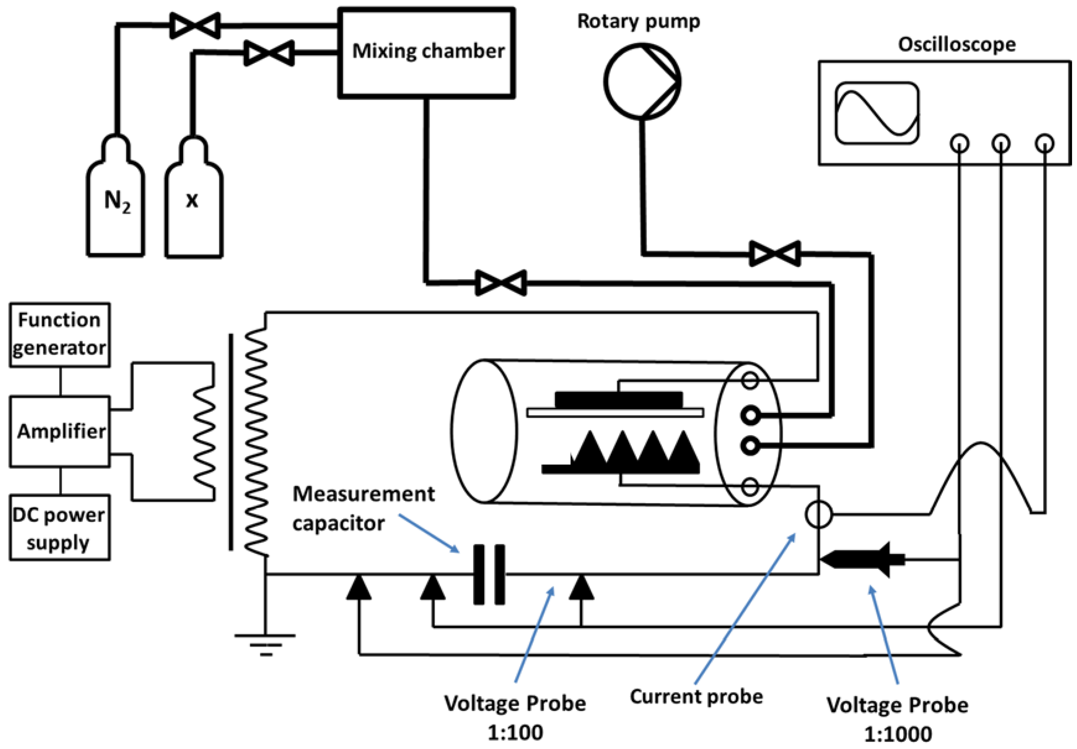
2.1. Design of Process Chamber

Although the experiments in this project were performed at atmospheric pressure, the DBD was housed inside a chamber that could be evacuated to a pressure of 1300 Pa with a rotary vacuum pump and then backfilled to atmospheric pressure (measured with a differential manometer) with the desired process gas or gas mixture. This arrangement ensured that the atmosphere in the chamber could be controlled during operation and prevented any contact with live components. The process chamber included a hollow glass cylinder 120 mm in diameter and 150 mm in length, with cover plates at either end. One cover plate contained only a window, whereas the other plate included a pumping port, two electrical feedthroughs for the high voltage cables to supply the electrode configuration and ports for process gas feeds. The latter were connected to gas bars with regular holes along their length to ensure uniform distribution of gas inside the reactor. The gas bars ran the length of the chamber and were used to clamp the cover plates against the cylinder to form a chamber. They also provided a mounting bracket for the electrode configuration.

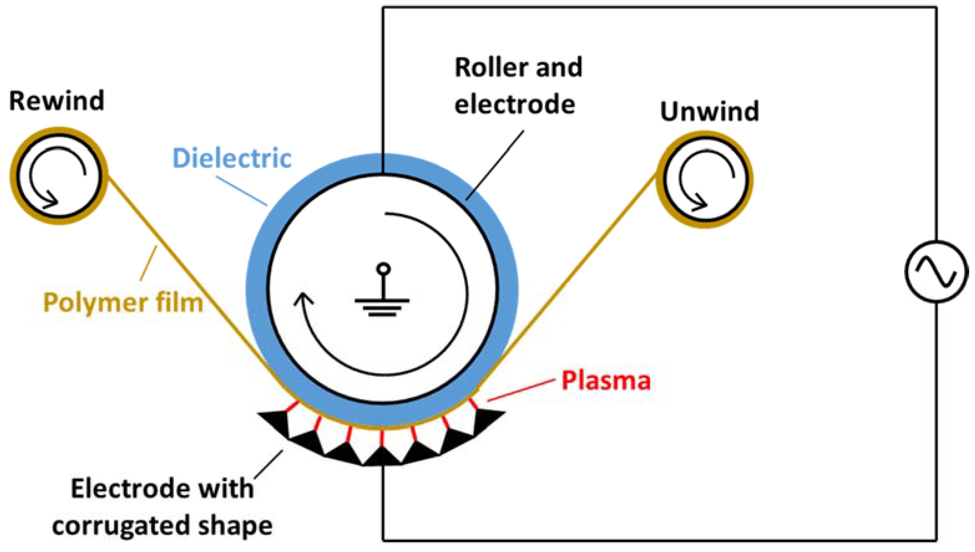
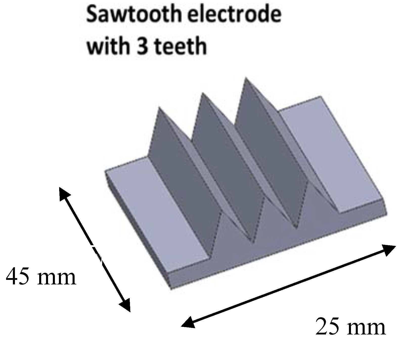
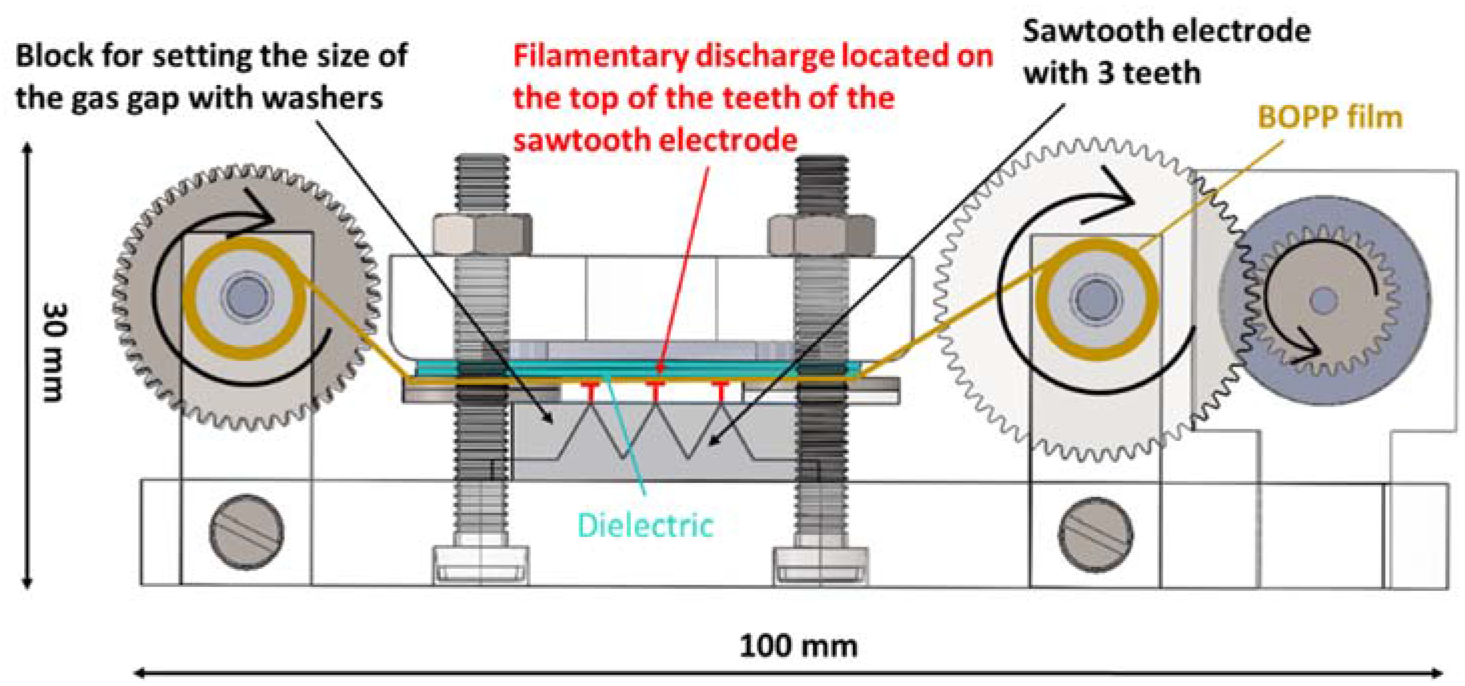
2.2. Design of the DBD Reactor

The DBD electrode configuration with the reel-to-reel system was designed to be placed on the bracket formed by the gas bars inside the process chamber. Both upper and lower electrodes were held parallel to each other and at a fixed separation by four bolts and a specific number of fibre washers. The washers had a thickness of 0.5 mm, meaning that the gap between them could be changed in increments of 0.5 mm by adding the required number of washers.
The upper electrode in this configuration was made of a flat piece of stainless steel of dimensions 34 mm × 26 mm, which was fitted into a recess in a nylon holder, such that the surface of the electrode was flush with the surface of the holder. The corners of the electrode were rounded with radii of 5 mm and the upper edge with a radius of 1.5 mm to avoid increased electrical fields through edge effects. Sheets of a dielectric material can be clamped between the washers and the electrode. In this case, alumina sheets were used as the dielectric, with each sheet having a thickness of 0.63 mm. The nylon holder had a cut out, through which a high voltage cable was connected to the rear surface of the electrode.
The counter electrode had a sawtooth profile with three teeth and was manufactured from aluminium (shown schematically in Figure 2). The sawtooth electrode is directly fixed onto the base plate of the reel-to-reel mechanism. The corrugated shape of the sawtooth electrodes concentrates the streamers of the filamentary discharge at the top of the teeth. Thus it is possible to ignite the streamers very close to each other and spatially align them, relative to the web.
The reel-to-reel web transport system consisted of two reels (unwind and re-wind) mounted on a base plate with two brackets, such that as the re-wind reel is driven by a DC motor, and the polymeric web is drawn through the gas gap between the two electrodes at a speed of 0.37 ms−1. The system was designed to ensure that the web was held in contact with the dielectric covering the upper electrode. The DC motor and gears used did not allow a wide range of web transport speeds to be investigated, thus this parameter was not varied in these experiments. The DBD reactor is shown schematically in Figure 3.

2.3. Power Supply Unit

The high voltage power supply for the DBD reactor consisted of a function generator (TG 2000 20 MHz DDS, Aim-TTi, Huntingdon, UK), a DC power supply (GPR-11H30D, GW Instek, New Taipei City, Taiwan), an amplifier, and a transformer (AD6170, Amethyst-designs, Cambridge, UK). The maximum settings of the DC power supply are 110 V and 3 A. The amplifier processes the signals from the function generator and the DC power supply and gives an AC signal to the transformer, which transforms the low voltage signal to a high voltage sinusoidal signal, which is then applied to the electrode configuration. A current probe (Pearson current monitor model 4100, Pearson Electronics, Palo Alto, CA, USA) and a voltage probe (PVM-6, 1000:1, North Star High Voltage, Bainbridge Island, WA, USA) were used to measure the applied voltage and the discharge current on the high voltage side of the electrical circuit via an oscilloscope (Tektronix DPO 3014, Beaverton, OR, USA). The plasma is ignited by a high electrical field, where the field strength is defined as voltage divided by electrode separation. After ignition, the output is regulated on current, with the voltage floating up to the level required to deliver the desired current. To be able to calculate the discharge power, a measurement capacitor (TDK Corporation, Tokyo, Japan) with a capacitance of 560 pF is connected in series to the electrode configuration. The voltage drop can be measured across the capacitor with a voltage probe (GE-3121, 100:1, Elditest, St Etienne, France). The complete experimental setup, excluding the reel-to-reel web transport mechanism, is shown in Figure 4.
The discharge power, Pd, was calculated using the following equation from the voltage applied to the gas gap, Vgap, and the plasma current, Iplasma, according to [26]:
P d = 1 T 0 T V g a p ( t ) · I p l a s m a ( t ) d t
The voltage applied to the gas gap, Vgap, derives from the subtraction of the voltage drop across the dielectric layer, Vdie, and of the voltage drop across the measurement capacitor, Vd, from the voltage applied to the electrode configuration, Va, as shown by Equation (2):
V g a p ( t ) = V a ( t ) V d i e ( t ) V d ( t )
The voltage drop across the measurement capacitor, Vd, and the voltage applied to the electrode configuration, Va, are directly measured. This is not possible for the voltage drop across the dielectric layer, which needs to be calculated. Mangolini, et al. [27] states that the voltage drop across the dielectric layer is proportional to the voltage drop across the measurement capacitor and can, thus, be calculated by the following equation:
V d i e ( t ) = c m e a s c d · V d ( t )
The capacitance of the measurement capacitor, Cmeas, is known. The capacitance of the dielectric layer, Cd, was estimated manually from Lissajous figures [5,28] presented elsewhere [29], which show the charge transferred during the discharge as a function of the applied voltage of the high voltage circuit.

2.4. Treatment of BOPP Film in Nitrogen

An experimental array was developed to investigate the influence of specific process parameters during the treatment of the BOPP film in a nitrogen atmosphere and to identify the optimum operating conditions for the DBD reactor. The following three factors were chosen for the experimental array:
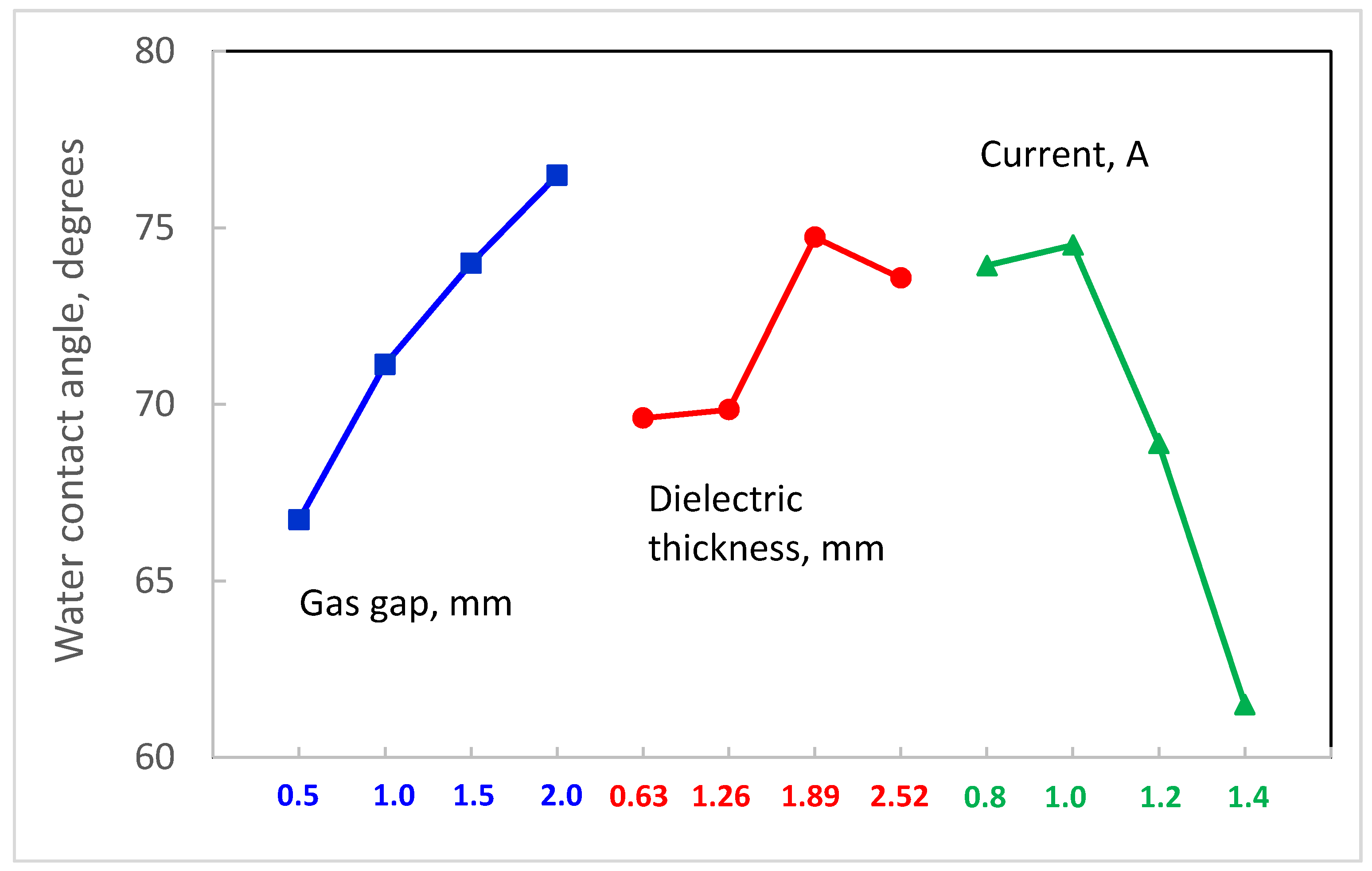
  • the thickness of the dielectric covering the upper electrode (four levels were tested: 0.63 mm, 1.26 mm, 1.89 mm, 2.52 mm)
  • the size of the gas gap measured between the upper electrode and the top of the teeth on the sawtooth electrode (0.5 mm, 1.0 mm, 1.5 mm, 2.0 mm)
  • the DC power supply current setting (0.8 A, 1.0 A, 1.2 A, 1.4 A)
These factors and values represent the practical extent of the process envelope for this system. The optimal frequency of the function generator for this experimental configuration was found to be between 29.6 and 29.9 kHz. All other factors were kept constant throughout the array. Based on the D-optimal approach, the experimental array that was developed from these parameters is listed in Table 1. Each experiment was repeated three times.
The experimental procedure was as follows. A 30-cm-long, 3-cm-wide BOPP sample was fixed to the reel-to-reel system with adhesive tape. The untreated side of the BOPP film faced the gas gap and the whole film was coiled on the unwind reel. The reel-to-reel system was then placed on its bracket inside of the plasma chamber, which was then sealed with the end cap. The rotary pump was used to evacuate the chamber to a minimum pressure of 1300 Pa. When this pressure was reached, the nitrogen gas valve was opened. The rotary pump was allowed to run for a further 2 min to flush the chamber with the process gas. The pressure inside the chamber was set to a slight overpressure of 1.05 bar to prevent the surrounding air entering the chamber.
After the plasma treatment, the process chamber was opened and the BOPP film removed from the reel-to-reel system. Ten drops of distilled water were placed along the centre line of the treated surface of the BOPP film at a separation of approximately 1 cm from each other and the contact angles of these drops were measured. Contact angle measurements were made at room temperature using the sessile drop technique and 5-µL volumes of solution on a Kruss goniometer (Hamburg, Germany) and data analysis system [30]. The average of the ten contact angles was taken as the response of the experimental array. The first distilled water drop was placed 7 cm away from the end of the sample that had been attached to the rewind, as this section of film did not pass between the electrodes.
Mean values of contact angle were taken for each experiment and from these values, level averages were calculated for each level of each factor. These level averages indicated the relative influence of each factor on the water contact angle and the direction of any trend with the variable. Based on these findings, operating conditions were selected to minimise the water contact angle for subsequent experiments.

2.5. Treatment of BOPP Film in Nitrogen with Admixtures

In the following set of experiments, the BOPP film was treated under the optimal conditions determined in the initial set of experiments in a nitrogen atmosphere also containing admixtures of a second gas at low concentration. The dopant gases were acetylene, nitrous oxide and carbon dioxide and four different concentrations of the admixtures; 125 ppm, 250 ppm, 375 ppm and 500 ppm, were investigated in the DBD reactor.
The settings for the surface treatment were a current setting of 1.4 A on the DC power supply, a gas gap distance of 0.5 mm and a dielectric thickness of 0.63 mm. Three samples of BOPP were treated for each concentration of the different admixtures.
Water contact angle measurements were used in the initial set of experiments to quickly allow optimal conditions to be identified. For these samples, in addition to measuring the water contact angle, contact angle measurements were also made with ethylene glycol and diiodomethane to allow surface energy values to be calculated. This gives a more meaningful value to assess the treatment and compare to other techniques. These measurements were made immediately after the surface treatment had taken place. Ten contact angles measurements were conducted for each sample for each testing liquid. The three test liquids chosen for this project, distilled water, diiodomethane and ethylene glycol, were selected because they have been used previously by other researchers to investigate the surface energy of polypropylene [31,32]. A total of 5 µL of HPLC grade water or diiodomethane or ethylene glycol were dropped onto a horizontal sample using a syringe. Physico-chemical parameters were calculated from the contact angles using the three solvents and their properties, and the Owens–Wendt–Rabel–Kaelble method [33,34]. This theory divides the surface energy into two components: the polar and the dispersive part. The polar part describes the sum of the polar interactions, such as hydrogen bonds, as well as dipole–dipole and acid–base interactions. The dispersive interactions are based on temporary variations in the electron density of the molecules [35,36]. The calculation of the dispersive part, the polar part and the surface energy was conducted with the averaged value of the ten measurements.

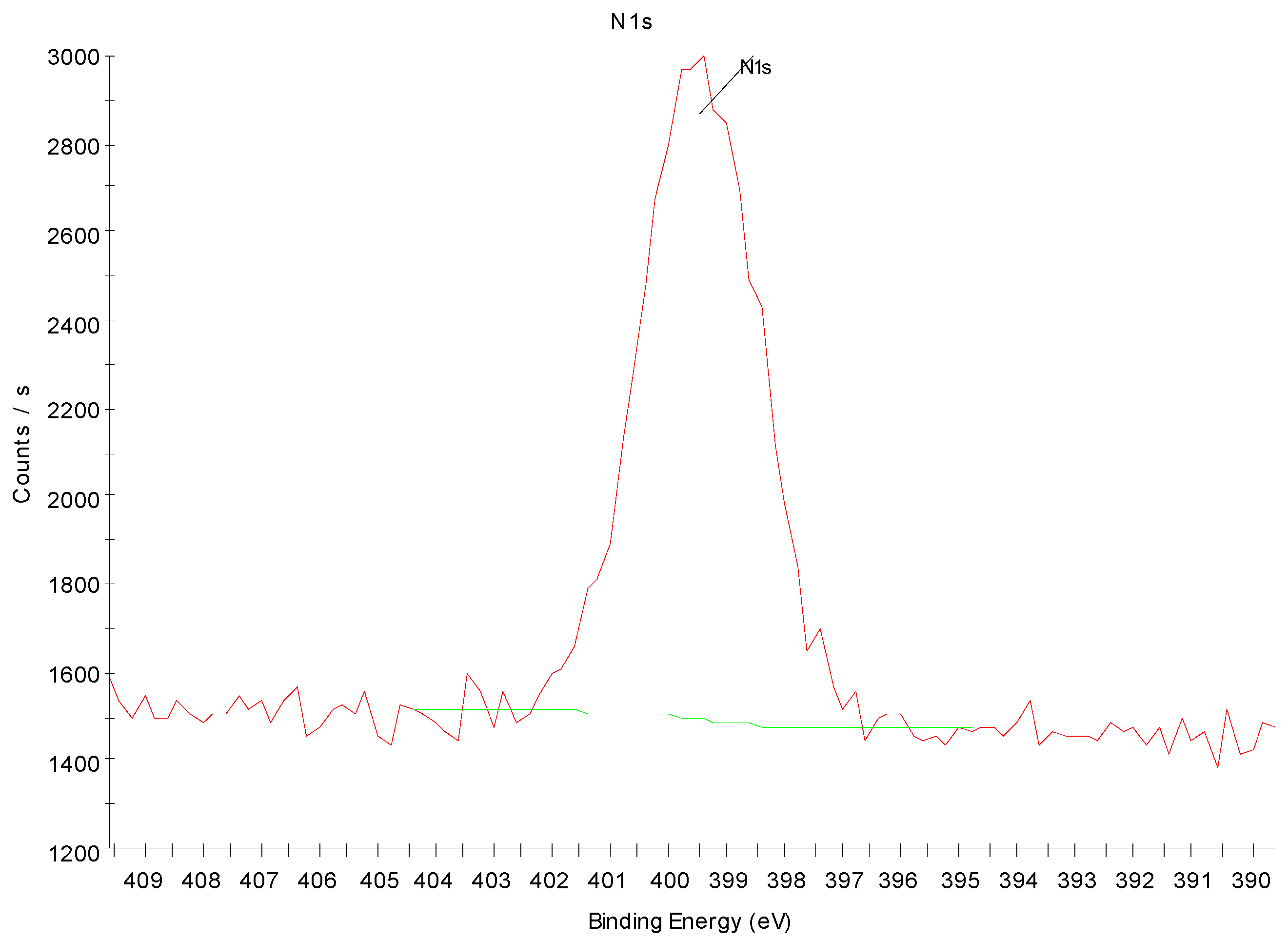
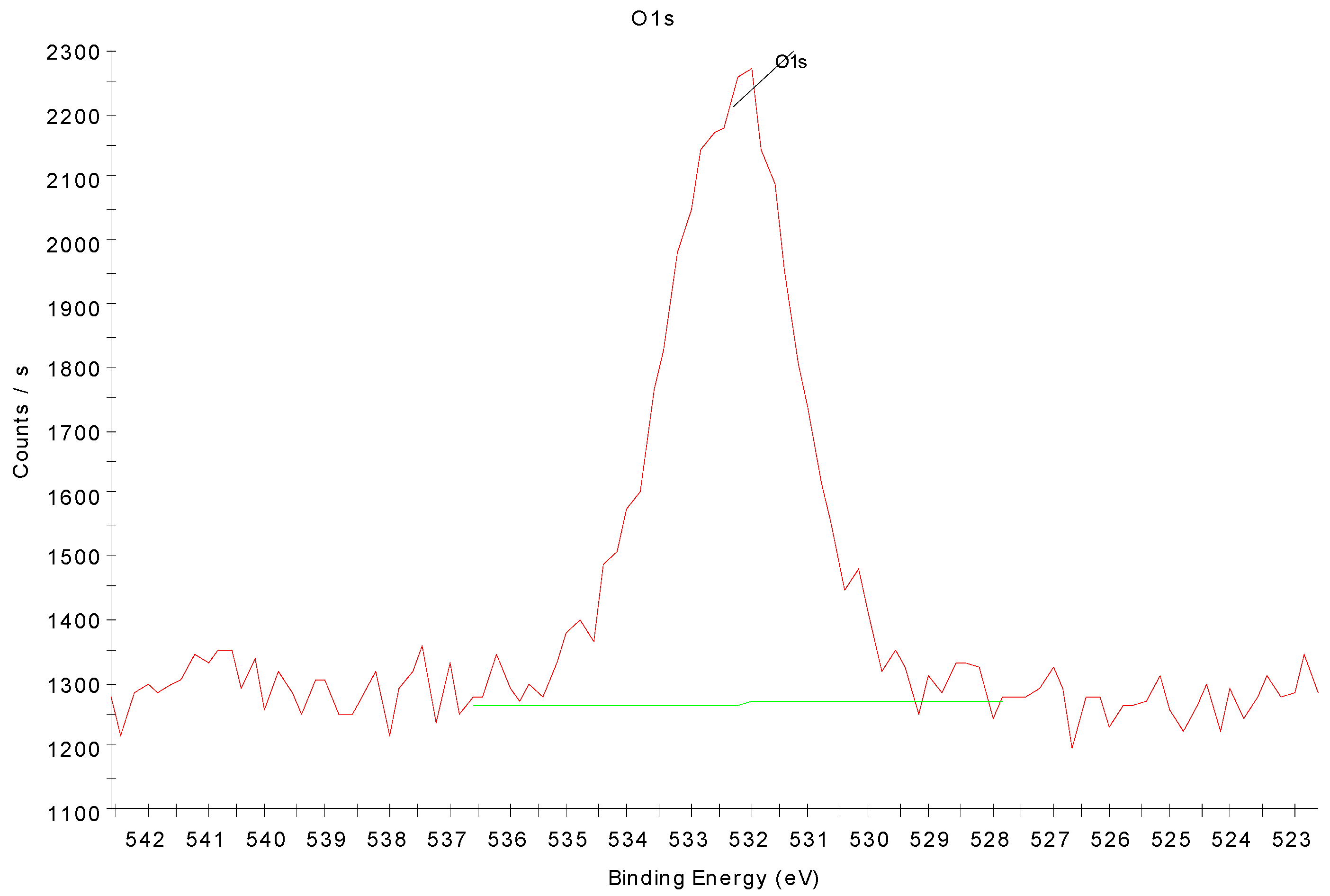
2.6. X-ray Photoelectron Spectroscopy Analysis of Surface Chemistry

To investigate changes in the surface chemistry of the films treated in pure nitrogen under the optimum conditions described in Section 2.5, a theta probe, angle-resolved X-ray photoelectron spectrometer (Thermo Fisher Scientific Inc., Waltham, Massachusetts, USA) with an aluminium K-alpha X-ray source (1486.6 eV) was used to measure a spot of 700 μm2 on every sample. Wide scans from 0 to 1400 eV were conducted to identify the elements present at the surface of the sample and narrow scans of the 1 s peaks of carbon (282–290 eV), nitrogen (395–404 eV) and oxygen (528–537 eV) were measured to determine the elemental composition. For comparison purposes, an untreated sample was also analysed.

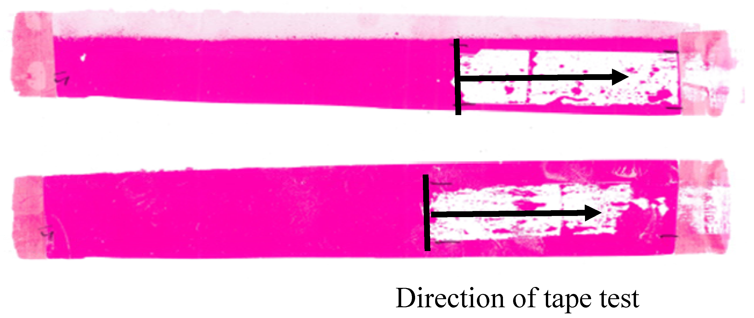
2.7. Dyne Pen and Ink Adhesion Tests

In addition to the contact angle measurements and surface energy calculations, the films treated in pure nitrogen under optimum conditions were investigated using Dyne pens and ink adhesion tests. Dyne pens are filled with a coloured ink and different solvents. The combination of the solvents determines the surface energy of the ink-solvent mixture, which is indicated on the side of the pen. The test method utilising Dyne pens forms the basis of the ASTM D2578 Standard [37]. A continuous line is drawn with the pen on the treated BOPP film to be investigated and afterwards the wetting ability of the ink-solvent mixture is evaluated visually. If the ink-solvent mixture wets the BOPP film properly, the value of surface energy of the film is equal to or greater than the value written on the pen used. If the wetting is poor, the ink solvent mixture starts to form droplets on the sample and the drawn line is thus not consistent, i.e., the ink does not wet the film. In this case, the surface energy of the film is lower than the value on the pen.
Ink adhesion tests were carried out using a UV curable ink and two solvent-based inks. The samples were printed with Sericol JD UV flexographic ink (Broadstairs, UK) at a coat weight of 1 g/m2 before curing with three passes of the UV curer at 120 wattscm−1 lamp power at a speed of 1.8 mmin−1. The samples were also printed with Sun Chemical’s Tornado cellulose acetate propionate (CAP)/acrylic ink and Sunprop nitrocellulose polyurethane (NCPU) ink using a red K-bar which applies a wet film deposit of approximately 12 µm. Immediately after drying in air, the samples were tested for ink adhesion with Scotch magic tape type 810. A length of tape was pressed onto the sample and then quickly removed in one motion. The solvent-based ink adhesion test was performed across the transverse direction of the film to ensure that the treated area was tested. For these final tests, the samples were plasma treated in a slightly modified reactor, which allowed greater web widths to be handled, but operated under the same process parameters.

3. Results and Discussion

3.1. Characterisation of the DBD

The voltage applied to the electrodes and the discharge current were measured using voltage and current probes. Ten thousand measurements were recorded over a 2.0 × 10⁻⁴ s time period. This corresponds to five recorded cycles of the sinusoidal voltage and discharge current, which are illustrated by way of example for experiment 1 of the experimental array (Figure 5).
The applied voltage and the discharge current in Figure 5 are phase-shifted by approximately 90 degrees. The voltage follows the current. The reason for these two effects are the capacitive properties of the electrode configurations. The discharge current has also a sinusoidal shape, but in addition, several high frequency peaks are superimposed at the maximum amplitude. The sinusoidal part of the discharge current is the displacement current, which is created by the changing polarisation of the applied electrical field, which causes the displacement of electric particles in the nitrogen gas and the dielectric. The displacement current flows independently of whether the plasma is ignited or not.
The high frequency peaks superimposed on the current signal originate from the ignited plasma. They mark the increased current flow while the gas loses its dielectric properties and becomes conductive due to the high amount of free charge carriers in the plasma. The individual peaks are very narrow, which corresponds to a short burning time of the individual filaments in the nanosecond range. This clearly indicates that the discharge regime is filamentary.
The observable difference of the current peak size on each half of the sinusoidal waveform is a result of the asymmetric electrode configuration, which combines a flat electrode with a sawtooth electrode. It is assumed that the sawtooth electrode is the cathode during the negative polarisation of the current. The seed electrons, which are accelerated from the cathode to the anode, would then receive more kinetic energy during the negative polarisation at the beginning of their acceleration, because the electrical field is strongly increased near the points of the teeth in the sawtooth electrode due to the edge effect. As a result of the increased kinetic energy, these seed electrons can cause more ionisation, which increases the current because more free electrons travel from the cathode to the anode. In the reverse case, when the seed electrons start near the flat electrode, which is then the cathode during the positive polarisation, their kinetic energy is not additionally increased by an edge effect. Thus, the current peaks are lower during the positive polarisation. Discharge powers estimated for each set of conditions in the experimental array are listed in Table 2.

3.2. Effect of Nitrogen Treatment on Water Contact Angle

The water contact angle for the untreated BOPP was 103°. This was reduced to values in the range 59° to 82° following treatment in nitrogen in the DBD reactor. The average water contact angle for three repeats of each set of experimental array conditions are listed in Table 2. The level averages calculated for each level of each factor in the experimental array are presented in Figure 6. This figure indicates that the water contact angle increases with increasing gas gap and dielectric thickness, but decreases with increasing current. It also implies that current and gas gap have a greater influence on contact angle than dielectric thickness, which has a relatively minor effect. Consequently, the optimum operating conditions to minimise contact angle, i.e., to maximise surface energy, are maximum current (1.4 A), minimum dielectric thickness (0.63 mm) and minimum gas gap (0.5 mm).
It might be expected that, over a certain range of conditions, there would be a negative correlation between water contact angle and discharge power density, i.e., the power delivered per unit area of treated film, but this was not apparent from the data obtained here. A similar relationship has been reported in a static system with parallel electrodes, where the reduction in contact angle increased with treatment time (i.e., total power delivered) [28]. The lack of any correlation in this case may be due to the difficulty of accurately measuring the area of the sawtooth electrode over which the power is dissipated and the discharge occurs. Consequently, no conclusions can be made about the relationship between these parameters at this stage.

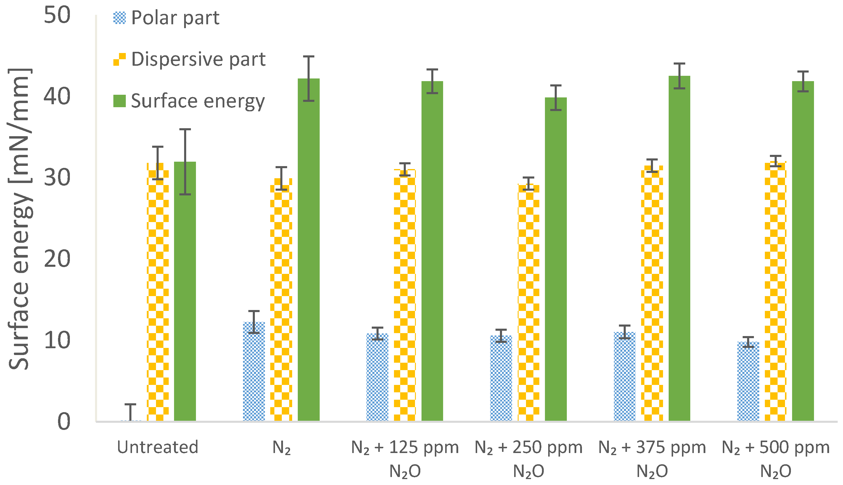
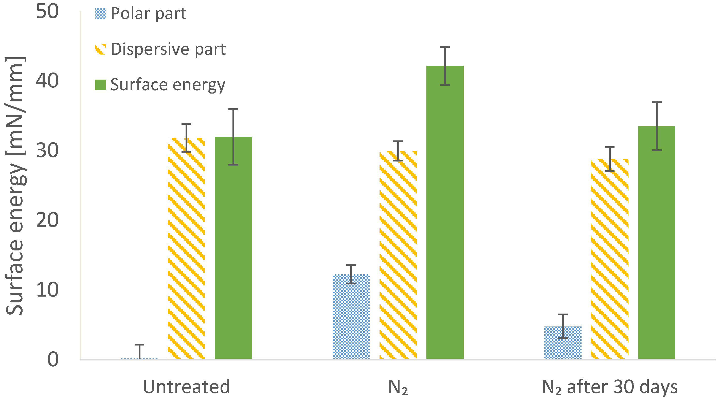
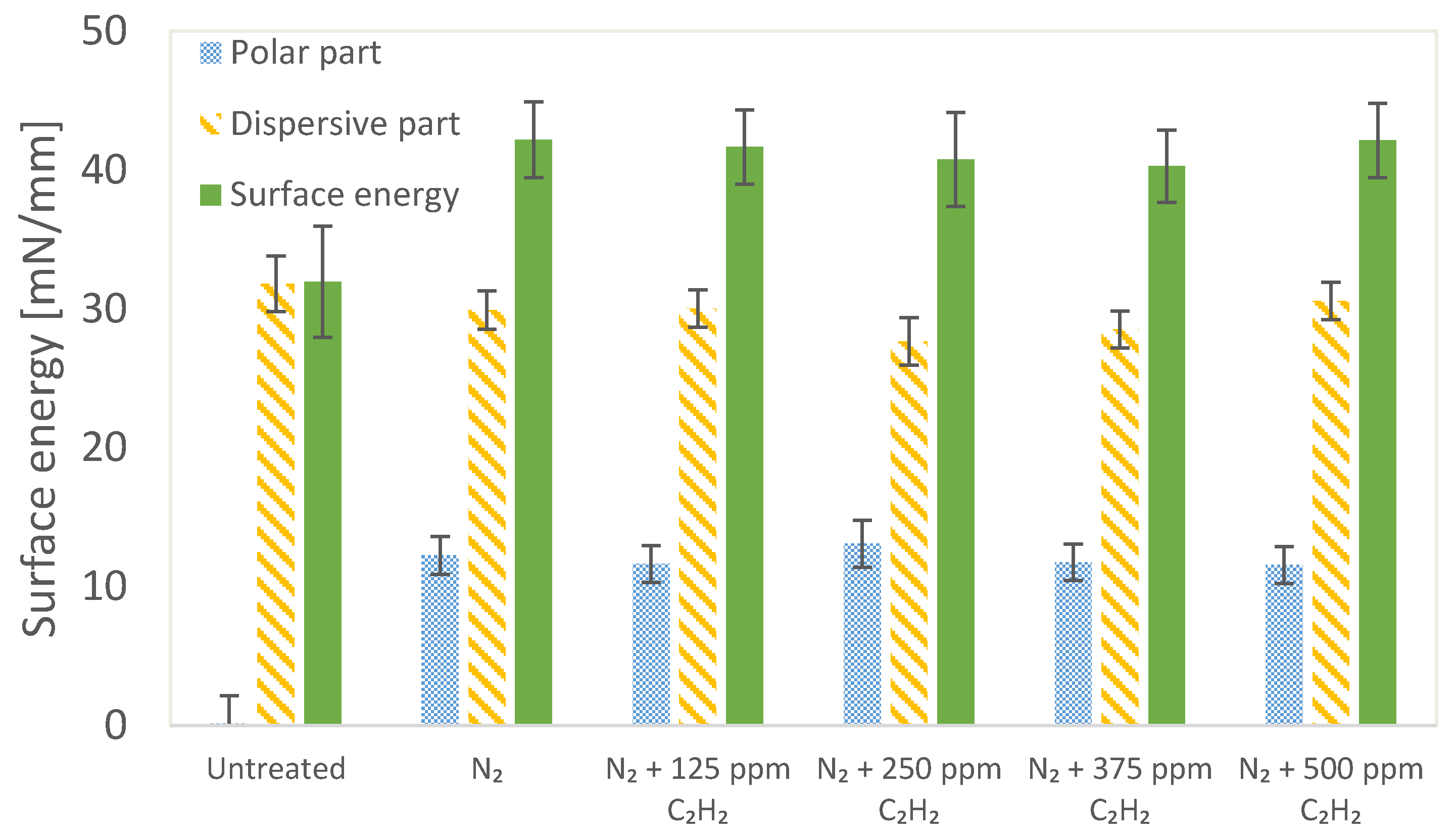
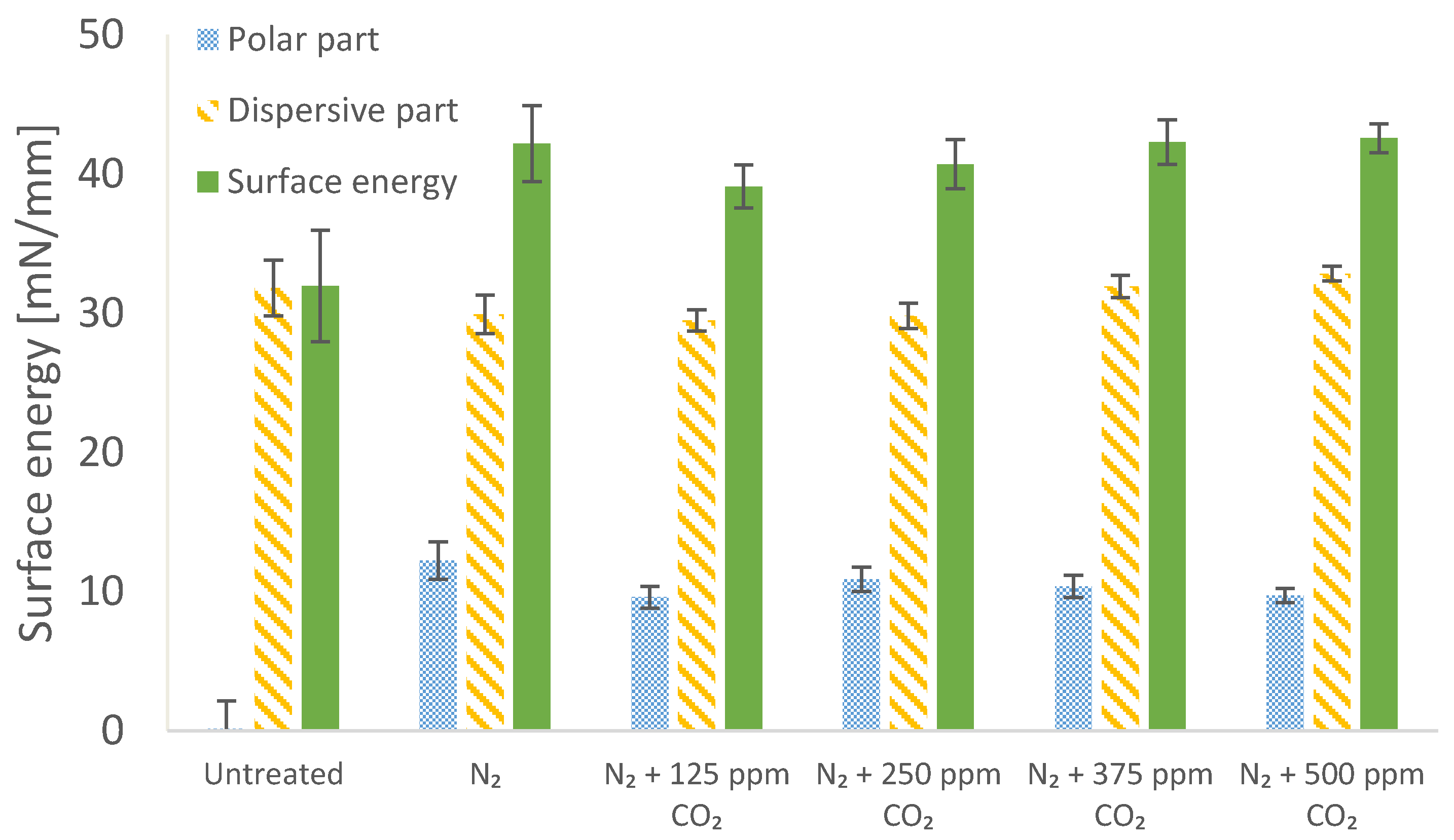
3.3. Effect of Nitrogen Treatment with Admixtures on Surface Energy

Calculations of surface energy showed that the plasma treatment significantly increased the polar part of the surface energy by approximately 10–14 mNm−1, whereas the dispersive part was unaffected. Thus, surface energy was increased by the DBD treatment from an untreated value of around 32 mNm−1 to values in the range of 42 to 46 mNm−1. However, there were no significant differences in the polar part, the dispersive part or the total surface energy between the treatment in pure nitrogen and the treatments in nitrogen with the different gas admixtures. This effect was also independent of the concentration of the admixture over the range tested. The results for the different gas admixtures and concentrations are shown in Figure 7, Figure 8 and Figure 9. The increase of the polar part of the surface energy is likely to be a result of the incorporation of electronegative chemical groups on the surface of the treated BOPP [38,39].
To investigate the stability of the surface energy of the treated BOPP films, also called hydrophobic recovery or aging behaviour [40,41], the contact angle measurements were repeated every 24 h over 30 days for the samples treated in pure nitrogen. The results in Figure 10 indicate that the surface energy of the BOPP films is substantially reduced 30 days after the plasma treatment with the DBD system. The polar part decreases from approximately 12 mNm−1 to 5 mNm−1 while the dispersive part is not affected. The total surface energy 30 days after the plasma treatment is only slightly higher than the untreated sample. The hydrophobic recovery of the plasma-treated films is related to the rearrangement of the polymer chains at the surface, which carry the electronegative chemical groups. The rearrangement leads to the reorientation of the electronegative chemical groups from the surface towards the bulk of the polymer and thus to the reduction of the polar part of the surface energy.

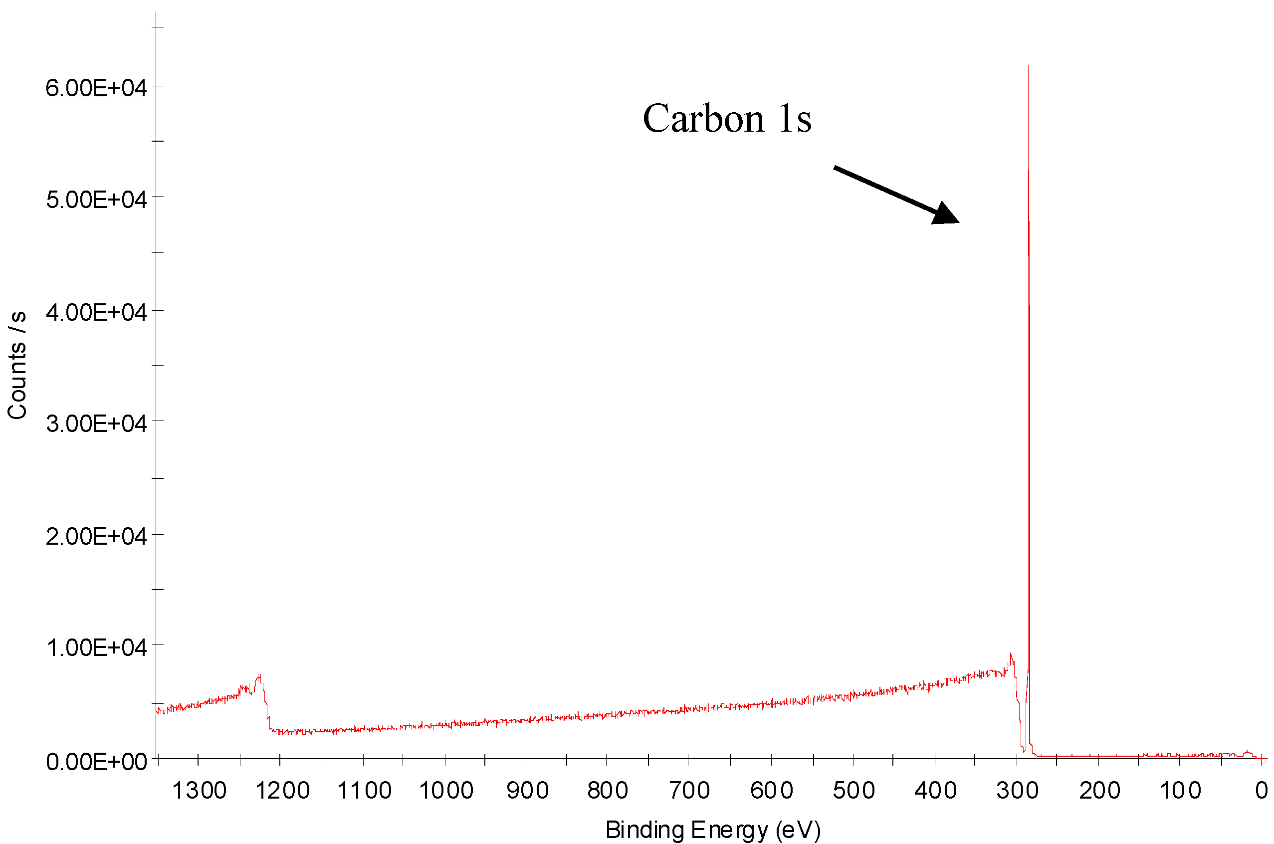
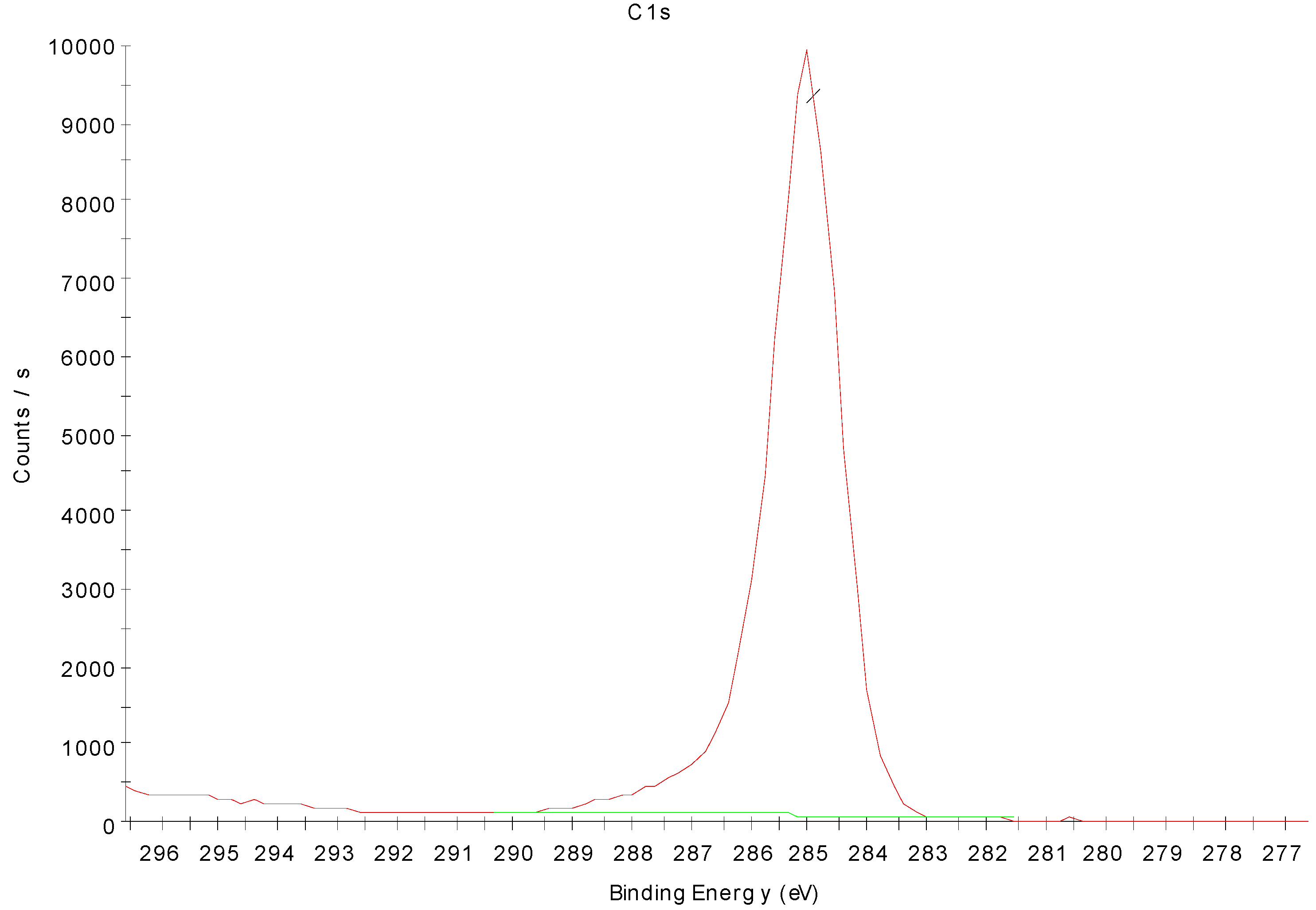
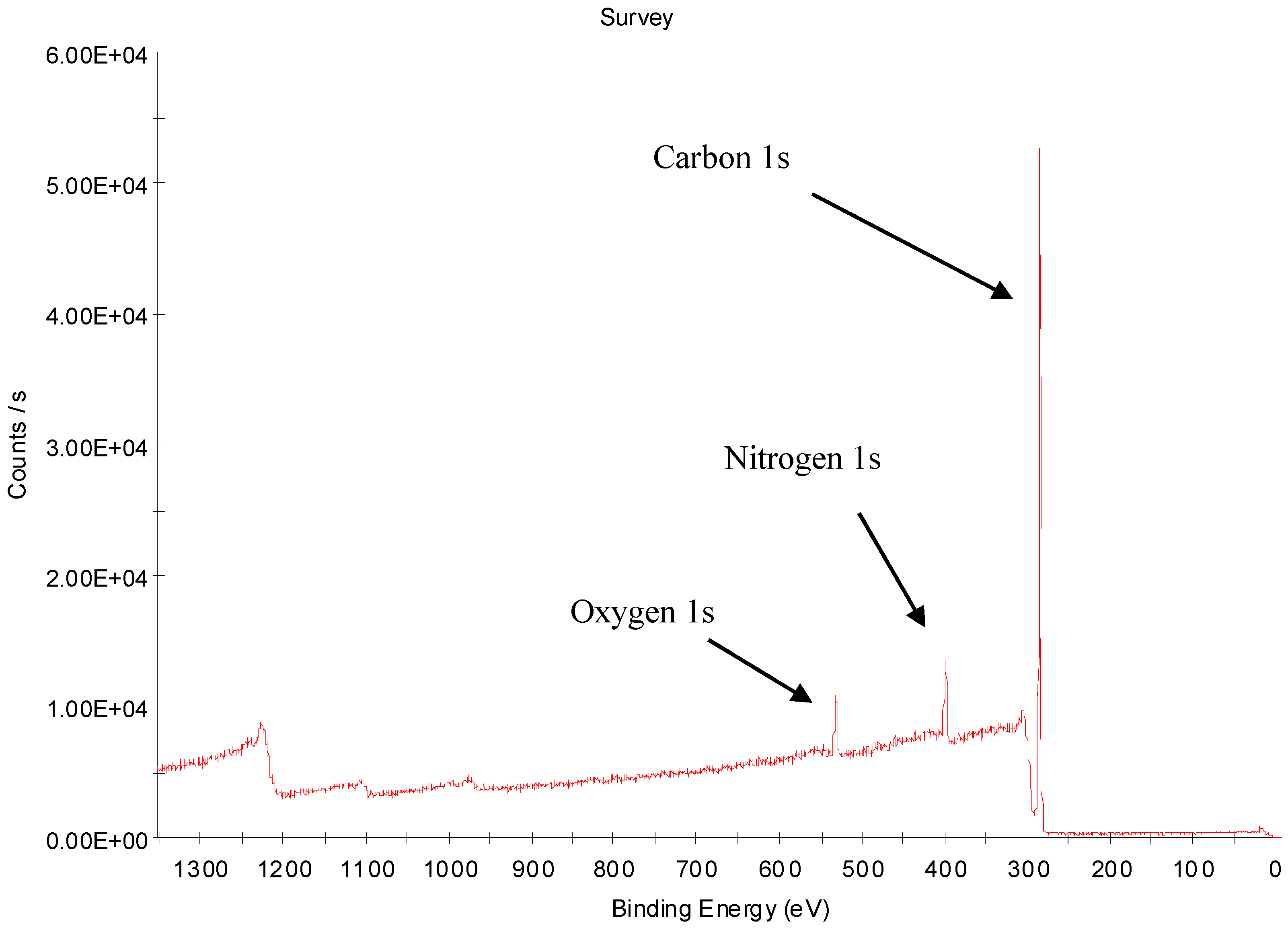
3.4. X-ray Photoelectron Spectroscopy Analysis of Nitrogen-Treated BOPP Film

The wide scans from 0 to 1400 eV to identify the elements present at the surface of the sample are shown in Figure 11 for an untreated sample and Figure 12 for sample treated with nitrogen. For the latter sample, the narrow scans of the 1 s peaks of carbon (282–290 eV), nitrogen (395–404 eV) and oxygen (528–537 eV) are shown in Figure 13, Figure 14 and Figure 15, respectively.
The XPS analysis of an untreated sample yielded a composition of 100% carbon, with no evidence of nitrogen or oxygen present in the surface. For the nitrogen-treated sample, the XPS measurements indicate that both nitrogen (7.2 at %) and oxygen (3.6 at %) atoms were incorporated in the surface of the treated BOPP films. Oxygen was detected on the treated samples despite the fact that the chamber was evacuated and backfilled with the process gases, which should only have contained oxygen in extremely low traces. However, comparison with the findings of other research groups indicates that their polypropylene films treated in pure nitrogen also contained oxygen [31,32,42,43]. This is usually attributed to the much higher reactivity of oxygen species in the plasma than nitrogen species. None of these publications, though, discuss the source of the incorporated oxygen. In addition to low residual background levels of oxygen in the reactor chamber, which may be entrained between the electrodes, it is assumed that the oxygen atoms also originate from water or oxygen adsorbed on the surface of the BOPP film. The relatively high amount of incorporated oxygen on the surface of the BOPP films, in comparison to the amount of incorporated nitrogen, leads to the assumption that it is mainly the excited particles, which are close to the surface of the BOPP film, that react with the polymer surface. Excited particles created further away from the surface have a lower probability of reacting with the polymer surface, because they have to overcome a longer diffusion distance in order to undertake a reaction with the surface of the polymer. If the atmosphere in the vicinity of the polymer contains the particles that mainly react with the surface of the polymer, then it is easily imaginable that substances adsorbed onto the polymer surface influence the composition of the gas in this region in greater concentrations than a few hundred ppm. The adsorbed substances thus have a greater impact on the surface treatment than the gaseous admixtures in the nitrogen. This theory would also explain why no significant differences could be measured in the surface energies of the samples treated with concentrations of up to 500 ppm of nitrous oxide, carbon dioxide and acetylene.

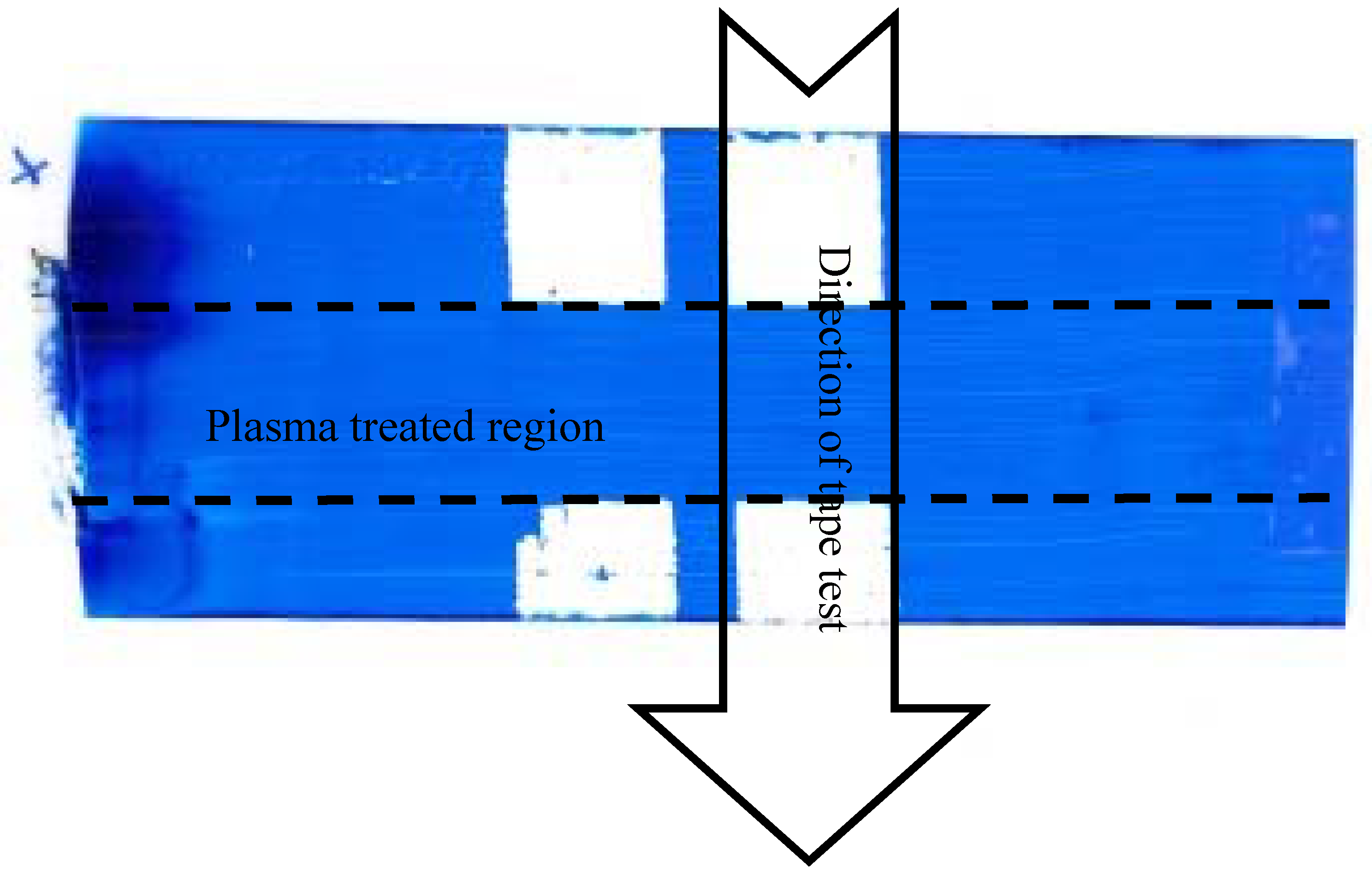
3.5. Dyne Pen and Ink Adhesion Tests

Dyne pen tests on the untreated BOPP indicated a surface energy in the region of 29 mNm−1, which is close to that calculated from the contact angle measurements (see Figure 7). Similarly, Dyne pen tests of the treated samples indicated values in the range 42 to 46 mNm−1.
Examples of the results for the ink adhesion tests are shown in Figure 16 and Figure 17. As can be seen, the samples had poor ink adhesion with the Sericol UV ink, with approximately 90% ink pull off (Figure 16), whereas the samples printed with the Tornado and Sunprop solvent-based inks had excellent ink adhesion; Figure 17 gives a typical example for the Sunprop ink. Outside the treated region the ink is completely removed, but inside the treated region the ink is well-adhered and no removal can be observed.

4. Conclusions

A laboratory-scale atmospheric pressure DBD reactor with a reel-to-reel web transport mechanism has been demonstrated. To simulate an industrial-scale system for web treatment, an electrode configuration was used, in which one electrode was flat and covered in a dielectric and the other had a sawtooth profile and was uncovered. A study of water contact angles measured after treatment of BOPP film in nitrogen showed that the contact angle could be significantly reduced by 20–40 degrees, depending on operating conditions. Level averages indicated that, of the conditions tested, contact angles were minimised for the lowest gas gap (0.5 mm), lowest dielectric thickness (0.63 mm) and highest current (1.4 A). Further experiments using these optimum conditions were carried out in nitrogen and nitrogen containing admixtures in the 125 to 500 ppm concentration range. Treatment of BOPP film under these conditions was found to increase the polar part of the surface energy of the film by 12–14 mNm−1. However, no differences were observed between the effect of a nitrogen discharge and discharges in nitrogen with admixtures of CO2, N2O or C2H2 over the range of concentrations tested. Furthermore, over 50% of this increase was lost through hydrophobic recovery over a 30-day period. XPS analysis indicated the presence of oxygen incorporated in the film surface after treatment, which appears to have reacted preferentially with the film surface, rather than the other gas additives present. Finally, Dyne pen tests corresponded to the values of surface energy calculated for the treated films and ink adhesion pull-off tests showed poor adhesion with UV-curable ink, but excellent adhesion with two types of solvent-based inks.

Acknowledgments

The XPS measurements for this project were performed by Steve Hinder from the University of Surrey. The authors acknowledge the support of Innovia Films Ltd. of Wigton, Cumbria for this project. Thanks, in particular, to Sue Nolan of Innovia for conducting the ink adhesion trials.

Author Contributions

P. Kelly, J.W. Bradley and L. Seidelmann conceived and designed the experiments; L. Seidelmann performed the experiments and analysed the data; J. Hewitt and J. Moffat provided technical support, materials and access to facilities at Innovia Films Ltd.; M. Ratova produced and tested the samples for ink adhesion trials; P. Kelly wrote the paper.

Conflicts of Interest

The authors declare no conflict of interest.

References

  1. Wolf, R.A. Atmospheric Pressure Plasma for Surface Modification; Wiley: New York, NY, USA, 2012. [Google Scholar]
  2. Thomas, M.; Mittal, K.L. Atmospheric Pressure Plasma Treatment of Polymers: Relevance to Adhesion; Wiley: New York, NY, USA, 2013. [Google Scholar]
  3. Shaw, D.; West, A.; Bredin, J.; Wagenaars, E. Mechanisms behind surface modification of polypropylene film using an atmospheric-pressure plasma jet. Plasma Sources Sci. Technol. 2016, 25, 065018. [Google Scholar] [CrossRef]
  4. Sun, C.; Zhang, D.; Wadsworth, L.C. Corona Treatment of Polyolefin Films—A Review. Adv. Polym. Technol. 1999, 18, 171–180. [Google Scholar]
  5. Ruddy, A.C. The Effect of Atmospheric Glow Discharge (APGD) Treatment on Polyetherimide, Polybutyleneterephthalate, and Polyamides. J. Plast. Film Sheet. 2006, 22, 103. [Google Scholar] [CrossRef]
  6. Kogelschatz, U. Dielectric-barrier discharges: Their history, discharge physics, and industrial applications. Plasma Chem. Plasma Process. 2003, 23, 1–46. [Google Scholar] [CrossRef]
  7. Aerts, R.; Tu, X.; Van Gaens, W.; Whitehead, J.C.; Bogaerts, A. Gas Purification by Nonthermal Plasma: A Case Study of Ethylene. Environ. Sci. Technol. 2013, 47, 6478–6485. [Google Scholar] [CrossRef] [PubMed]
  8. Moon, J.D.; Jung, J.S. Effective corona discharge and ozone generation from a wire-plate discharge system with a slit dielectric barrier. J. Electrost. 2007, 65, 660–666. [Google Scholar] [CrossRef]
  9. Ueno, H.; Kawahara, S.; Nakayama, H. Fundamental Study of Barrier Discharge and Ozone Generation Characteristics for Multiple Needles to Plane Configuration. Ozone Sci. Eng. 2011, 33, 98–105. [Google Scholar] [CrossRef]
  10. Helmke, A.; Wandke, D.; Mahmoodzada, M.; Weltmann, K.D.; Viol, W. Impact of Electrode Design, Supply Voltage and Interelectrode Distance on Safety Aspects and Characteristics of a Medical DBD Plasma Source. Contrib. Plasma Phys. 2013, 53, 623–638. [Google Scholar] [CrossRef]
  11. Schwabedissen, A.; Łaciński, P.; Chen, X.; Engemann, J. PlasmaLabel—A New Method to Disinfect Goods Inside a Closed Package Using Dielectric Barrier Discharges. Contrib. Plasma Phys. 2007, 47, 551–558. [Google Scholar]
  12. Kogelschatz, U.; Eliasson, B.; Egli, W. From ozone generators to flat television screens: History and future potential of dielectric-barrier discharges. Pure Appl. Chem. 1999, 71, 1819–1828. [Google Scholar] [CrossRef]
  13. Bobkova, E.; Rybkin, V. Peculiarities of Energy Efficiency Comparison of Plasma Chemical Reactors for Water Purification from Organic Substances. Plasma Chem. Plasma Process. 2015, 35, 133–142. [Google Scholar] [CrossRef]
  14. Rodriguez-Mendez, B.G.; López-Callejas, R.; Olguín, M.T.; Hernández-Arias, A.N.; Valencia-Alvarado, R.; Peña-Eguiluz, R.; Mercado-Cabrera, A.; Alcántara-Díaz, D.; Muñoz-Castro, A.E.; de la Piedad-Beneitezet, A. Bacterial inactivation in water by means of a combined process of pulsed dielectric barrier discharge and silver modified natural zeolite. J. Phys. D Appl. Phys. 2104, 47. [Google Scholar] [CrossRef]
  15. Shibata, T.; Nishiyama, H. Acetic Acid Decomposition in a Coaxial Dielectric Barrier Discharge Tube with Mist Flow. Plasma Chem. Plasma Process. 2014, 34, 1331. [Google Scholar] [CrossRef]
  16. Massines, F.; Sarra-Bournet, C.; Fanelli, F.; Naudé, N.; Gherardi, N. Atmospheric Pressure Low Temperature Direct Plasma Technology: Status and Challenges for Thin Film Deposition. Plasma Process. Polym. 2012, 9, 1041–1073. [Google Scholar] [CrossRef]
  17. Premkumar, P.A.; Starostin, S.A.; Creatore, M.; de Vries, H.; Paffen, R.M.J.; Koenraad, P.M.; van de Sanden, M.C.M. Smooth and Self-Similar SiO2-like Films on Polymers Synthesized in Roll-to-Roll Atmospheric Pressure-PECVD for Gas Diffusion Barrier Applications. Plasma Process. Polym. 2010, 7, 635–639. [Google Scholar] [CrossRef]
  18. Schäfer, J.; Horn, S.; Foest, R.; Brandenburg, R.; Vašina, P.; Weltmann, K.-D. Complex analysis of SiOxCyHz films deposited by an atmospheric pressure dielectric barrier discharge. Surf. Coat. Technol. 2011, 205, S330–S334. [Google Scholar] [CrossRef]
  19. Vinogradov, I.; Shakhatre, M.; Lunk, A. Spectroscopic Diagnostics of DBD Remote Plasma in Ar/Fluorocarbon Mixtures—Correlation Between Plasma Parameters and Thin Film Properties. Plasma Process. Polym. 2007, 4, S797–S800. [Google Scholar] [CrossRef]
  20. Niu, J.; Liu, D.; Wu, Y. Large-area and uniform surface modification of polymers by barrier discharge plasmas. Surf. Coat. Technol. 2011, 205, 3434–3437. [Google Scholar] [CrossRef]
  21. Papageorghiou, L.; Panousis, E.; Loiseau, J.F.; Spyrou, N.; Held, B. Two-dimensional modelling of a nitrogen dielectric barrier discharge (DBD) at atmospheric pressure: Filament dynamics with the dielectric barrier on the cathode. J. Appl. Phys. D Appl. Phys. 2009, 42, 105201. [Google Scholar] [CrossRef]
  22. Kanazawa, S.; Kogoma, M.; Moriwaki, T.; Okazaki, S. Stable glow plasma at atmospheric pressure. J. Appl. Phys. D Appl. Phys. 1988, 21, 838. [Google Scholar] [CrossRef]
  23. Fanelli, F. Thin film deposition and surface modification with atmospheric pressure dielectric barrier discharges. Surf. Coat. Technol. 2010, 205, 1536–1543. [Google Scholar] [CrossRef]
  24. Liston, E.; Martinu, L.; Wertheimer, W. Plasma surface modification of polymers for improved adhesion: A critical review. J. Adhes. Sci. Technol. 1993, 7, 1091–1127. [Google Scholar] [CrossRef]
  25. Cáceres, C.A.; Mazzola, N.; França, M.; Canevarolo, S.V. Controlling in-line the energy level applied during the corona treatment. Polym. Test. 2012, 31, 505–511. [Google Scholar] [CrossRef]
  26. Reichen, P. Plasma Surface Modification in the Afterglow of Micro-barrier Discharges. Ph.D. Dissertation, ETH Zürich, Zürich, Switzerland, 2009; p. 212. [Google Scholar]
  27. Mangolini, L.; Anderson, C.; Heberlein, J.; Kortshagen, U. Effects of current limitation through the dielectric in atmospheric pressure glows in helium. J. Appl. Phys. D Appl. Phys. 2004, 37, 1021. [Google Scholar] [CrossRef]
  28. Borcia, G.; Anderson, C.A.; Brown, N.M.D. Using a nitrogen dielectric barrier discharge for surface treatment. Plasma Sources Sci. Technol. 2005, 14, 259. [Google Scholar] [CrossRef]
  29. Seidelmann, L.J.W. Atmospheric Pressure Dielectric Barrier Discharges for the Surface Modification of Polypropylene. Ph.D. Thesis, Manchester Metropolitan University, Manchester, UK, 2015. [Google Scholar]
  30. Petrie, E.M. Theories of Adhesion. In Handbook of Adhesives and Sealants; McGraw-Hill: New York, NY, USA, 2007; pp. 39–58. [Google Scholar]
  31. Leroux, F.; Campagne, C.; Perwuelz, A.; Gengembre, L. Polypropylene film chemical and physical modifications by dielectric barrier discharge plasma treatment at atmospheric pressure. J. Colloid Interface Sci. 2008, 328, 412–420. [Google Scholar] [CrossRef] [PubMed]
  32. Šíra, M.; Trunec, D.; Stahel, P.; Buršíková, V.; Navrátil, Z.; Buršík, J. Surface modification of polyethylene and polypropylene in atmospheric pressure glow discharge. J. Appl. Phys. D Appl. Phys. 2005, 38, 621. [Google Scholar] [CrossRef]
  33. Owens, D.K.; Wendt, R.C. Estimation of the surface free energy of Polymers. J. Appl. Polym. Sci. 1969, 13, 1741–1747. [Google Scholar] [CrossRef]
  34. Kaelble, D.H. Dispersion-polar surface tension properties of organic solids. J. Adhes. 1970, 2, 66. [Google Scholar] [CrossRef]
  35. Zenkiewicz, M. Methods for the calculation of surface free energy of solids. J. Achiev. Mater. Manuf. Eng. 2007, 24, 137–145. [Google Scholar]
  36. Kwok, D.Y.; Neumann, A.W. Contact angle measurement and contact angle interpretation. Adv. Colloid Interface Sci. 1999, 81, 167–249. [Google Scholar] [CrossRef]
  37. ASTM D2578-09. Standard Test Method for Wetting Tension of Polyethylene and Polypropylene Films, ASTM International: West Conshohocken, PA, USA, 2009.
  38. Chvatalova, L.; Čermák, R.; Mráček, A.; Grulich, O.; Veseld, A.; Ponížil, P.; Minařík, A.; Cvelbard, U.; Beníčeka, L.; Sajdl, P. The effect of plasma treatment on structure and properties of poly(1-butene) surface. Eur. Polym. J. 2012, 48, 866–874. [Google Scholar] [CrossRef]
  39. Cui, N.Y.; Brown, N.M.D. Modification of the Surface Properties of a Polypropylene (PP) Film using an Air Dielectric Barrier Discharge Plasma. Appl. Surf. Sci. 2002, 189, 31–38. [Google Scholar] [CrossRef]
  40. Upadhyay, D.J.; Cui, N.Y.; Anderson, C.A.; Brown, N.M.D. Surface oxygenation of polypropylene using an air dielectric barrier discharge: The effect of different electrode–platen combinations. Appl. Surf. Sci. 2004, 229, 352–364. [Google Scholar] [CrossRef]
  41. Weikart, C.M.; Yasuda, H.K. Modification, degradation, and stability of polymeric surfaces treated with reactive plasmas. J. Polym. Sci. A Polym. Chem. 2000, 38, 3028–3042. [Google Scholar] [CrossRef]
  42. Guimond, S.; Wertheimer, M.R. Surface degradation and hydrophobic recovery of polyolefins treated by air corona and nitrogen atmospheric pressure glow discharge. J Appl. Polym. Sci. 2004, 94, 1291–1303. [Google Scholar] [CrossRef]
  43. Guimond, S.; Radu, I.; Czeremuszkin, G.; Carlsson, D.J.; Wertheimer, M.R. Biaxially oriented polypropylene (BOPP) surface modification by nitrogen atmospheric pressure glow discharge (APGD) and by air corona. Plasmas Polym. 2002, 7, 71. [Google Scholar] [CrossRef]
Figure 1. Schematic of industrial dielectric barrier discharges (DBD) configuration for the surface treatment of polymer webs.
Applsci 07 00337 g001
Figure 2. Sawtooth electrode design for DBD system.
Applsci 07 00337 g002
Figure 3. Schematic of reel-to-reel DBD system with sawtooth electrode configuration (the baseplate is 100 mm long × 50 mm wide). BOPP: biaxially-oriented polypropylene.
Applsci 07 00337 g003
Figure 4. Experimental setup of the laboratory scale DBD system with sawtooth electrode configuration.
Applsci 07 00337 g004
Figure 5. Measured voltage applied to the three-tooth electrode configuration and the resulting discharge current for experiment 1 of the experimental array.
Applsci 07 00337 g005
Figure 6. Level average water contact angles for array factors gas gap, dielectric thickness and current during the DBD treatment of BOPP in pure nitrogen.
Applsci 07 00337 g006
Figure 7. The polar part, the dispersive part and the surface energy of the BOPP films treated by the DBD system with admixtures of acetylene.
Applsci 07 00337 g007
Figure 8. The polar part, the dispersive part and the surface energy of the BOPP films treated by the DBD system with admixtures of nitrous oxide.
Applsci 07 00337 g008
Figure 9. The polar part, the dispersive part and the surface energy of the BOPP films treated by the DBD system with admixtures of carbon dioxide.
Applsci 07 00337 g009
Figure 10. Aging behaviour of the BOPP samples treated in nitrogen with the laboratory DBD system.
Applsci 07 00337 g010
Figure 11. X-ray photoelectron spectroscopy wide scan of untreated BOPP sample.
Applsci 07 00337 g011
Figure 12. X-ray photoelectron spectroscopy wide scan of BOPP sample treated in pure nitrogen.
Applsci 07 00337 g012
Figure 13. X-ray photoelectron spectroscopy narrow scan (Carbon 1 s) of the BOPP sample treated in pure nitrogen.
Applsci 07 00337 g013
Figure 14. X-ray photoelectron spectroscopy narrow scan (Nitrogen 1 s) of the BOPP sample treated in pure nitrogen (7.2 at %).
Applsci 07 00337 g014
Figure 15. X-ray photoelectron spectroscopy narrow scan (Oxygen 1 s) of the BOPP sample treated in pure nitrogen (3.6 at %).
Applsci 07 00337 g015
Figure 16. Ink adhesion test results for UV curable flexographic ink on N2-treated BOPP.
Applsci 07 00337 g016
Figure 17. Ink adhesion test results for Sunprop nitrocellulose polyurethane (NCPU) solvent-based ink on N2-treated BOPP.
Applsci 07 00337 g017
Table 1. Design of experiments for the sawtooth electrode configurations for the treatment of BOPP in nitrogen.
Number of ExperimentCurrent [A]Thickness of the Dielectric [mm]Size of the Gas Gap [mm]Optimal Frequency [kHz]
10.80.632.029.8
21.40.630.529.6
31.21.260.529.6
41.20.632.029.8
50.80.630.529.6
61.01.892.029.9
70.82.522.029.9
80.81.891.529.9
91.00.631.529.8
100.81.260.529.6
110.81.891.029.7
120.80.631.029.6
130.81.262.029.9
141.21.262.029.9
151.20.630.529.6
160.82.520.529.7
Table 2. Estimated discharge power and average water contact angles for BOPP film treated in nitrogen.
Number of ExperimentDischarge Power [W]Average Water Contact Angle, Degrees
15.580.4
2561.5
35.367.6
4574.7
5571.7
66.876.9
78.579.8
86.775.8
94.672.2
105.468.3
116.871.5
12570.7
135.178.0
145.269.2
154.664.1
168.567.3

