Abstract
Vertical wire feeding with an axisymmetric multi-laser source (feeding the wire vertically into the molten pool) has exhibited great advantages over LAM (laser additive manufacturing) with paraxial wire feeding, which has an anisotropic forming problem in different scanning directions. This paper investigates the forming ability of vertical wire feeding with an axisymmetric multi-laser source, and the microstructure and mechanical properties of the fabricated components. It has been found that vertical wire feeding with an axisymmetric multi-laser source has a strong forming ability with no anisotropic forming problem when fabricating the complex parts in a three-axis machine tool. Most of the grains in the samples are equiaxed grains, and a small amount of short columnar grains exist which are parallel to each other. The microstructure of the fabricated samples exhibits a fine basket-weave structure and martensite due to the fast cooling rate which was caused by the small size of the molten pool and the additional heat dissipation from the feeding wire. The static tensile test shows that the average ultimate tensile strength is 1140 MPa in the scanning direction and 1115 MPa in the building direction, and the average elongation is about 6% in both directions.
1. Introduction
Ti-6Al-4V titanium alloy was widely used in the aerospace and military industries due to its excellent specific strength, high shear modulus, low density and thermal expansion coefficient [1,2,3]. However, traditional manufacturing methods of Ti-6Al-4V titanium alloy, such as forging or cutting, which have the disadvantages of a high buy-to-fly ratio and low manufacturing flexibility, are not economical. The laser additive manufacturing (LAM) process which fabricates Ti-6Al-4V titanium alloy with a near net shape has no restriction in the component shapes. It has been popular in recent studies [4,5,6,7] and has been widely used to fabricate complex components in aerospace and other industries [1]. The typical grain structure in the fabricated Ti-6Al-4V titanium alloy samples is coarse columnar prior β grains, which arise due to high temperature gradients and distribute approximately parallel to the building direction [8].
Wire and powder are the two main material forms of the Ti-6Al-4V in LAM process [6,9]. SLM (Selective Laser Melting) is a typical LAM method which uses powder as the feedstock. It has the advantages of high manufacturing capacity and accuracy. Compared with powder, using wire as the feedstock form has the great advantages of high efficiency, low cost and simple handling and storage operation during the manufacturing process [9,10]. Therefore, it has received more attentions in recent research activities [11,12,13,14,15,16].
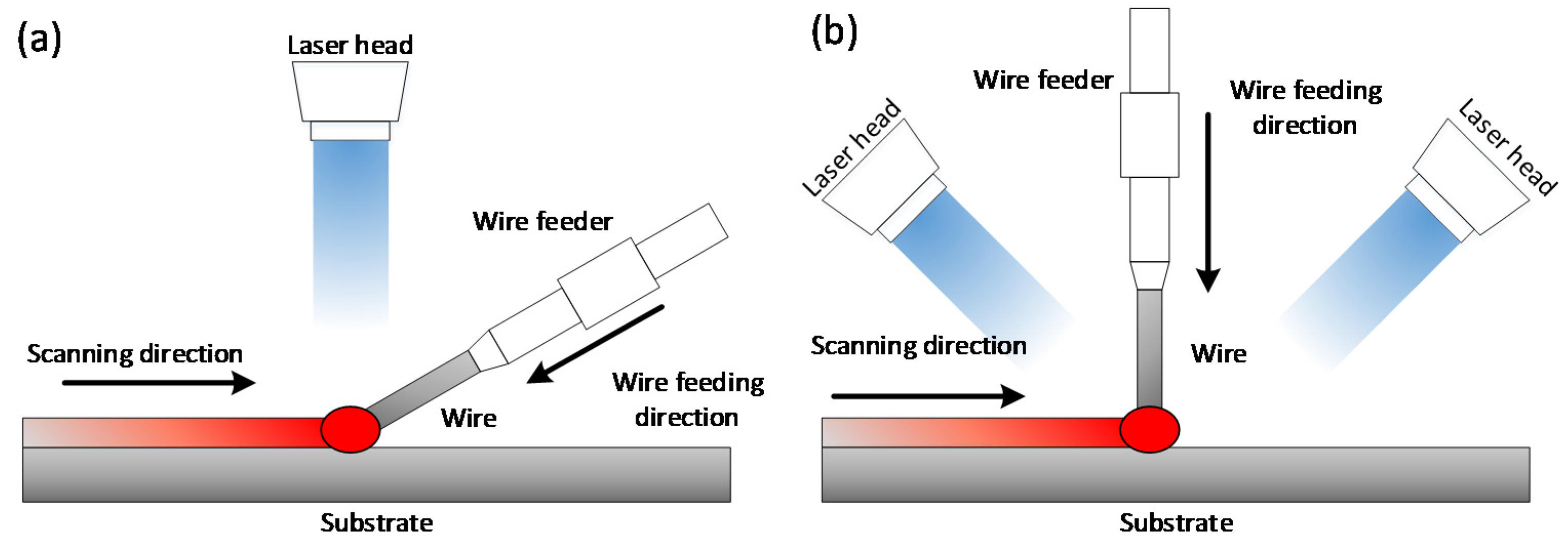
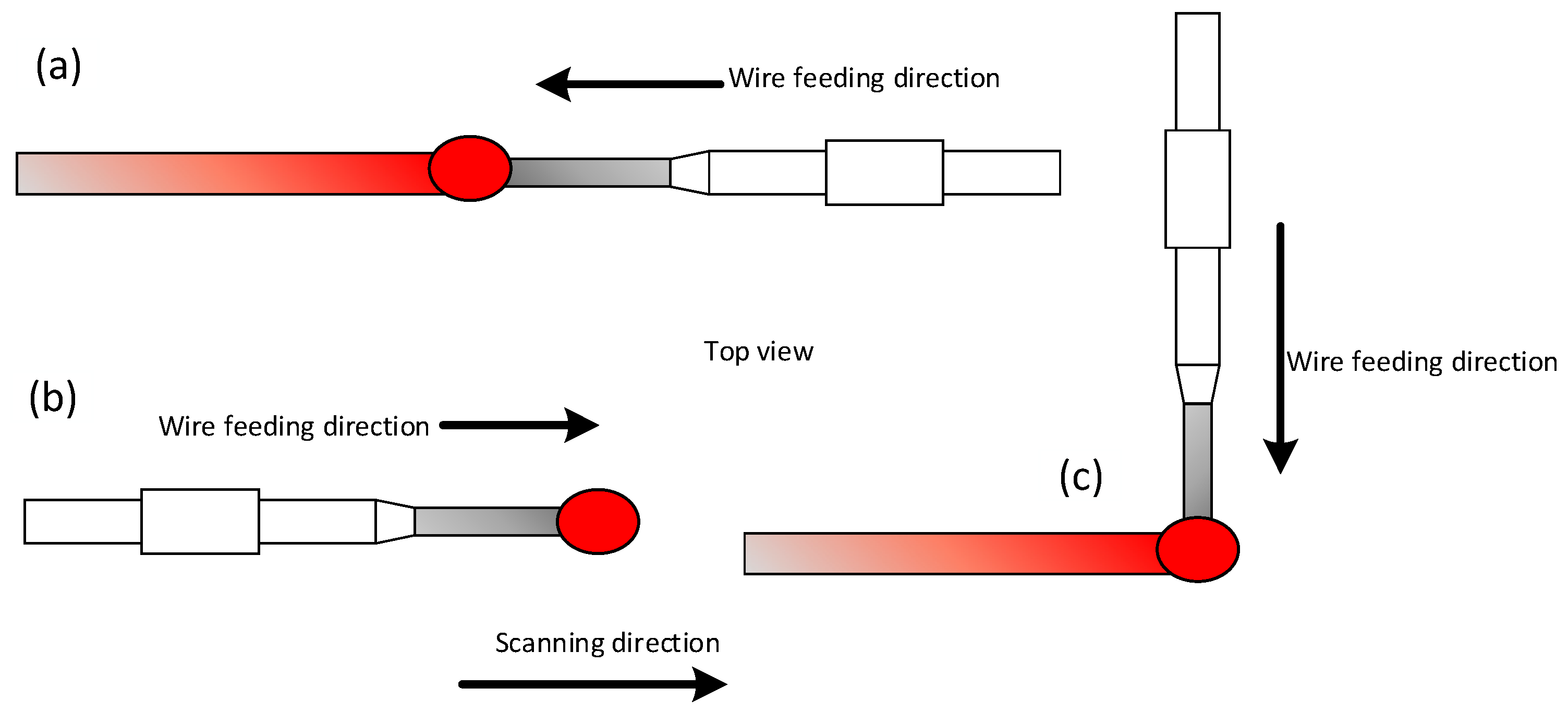
LAM with wire feeding can be divided into vertical wire feeding and paraxial wire feeding [9,17]. LAM with wire feeding evolved from laser wire feed welding, so paraxial wire feeding accounts for the majority of the wire feeding methods, and the schematic drawing of it is indicated in Figure 1a. Although it is easy to implement, there is an anisotropic forming problem in the deposition process due to different wire feed orientations [18]. There are three kinds of wire feed orientations in the deposition process, which are shown in Figure 2. The depositions from front feeding and side feeding have a smoother surface than back feeding [19], and the smoothest surface can be obtained when the wire is positioned at the leading edge of the molten pool in front feeding [20]. Due to the different forming morphologies in different wire feed orientations, different layer thicknesses may appear in the same layer, especially when forming large complex components.

Figure 1.
The schematic of laser additive manufacturing with: (a) paraxial wire feeding; (b) vertical wire feeding.
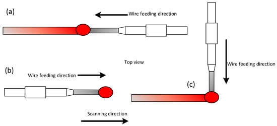
Figure 2.
The schematic of wire feed orientations: (a) front feeding; (b) back feeding; (c) side feeding.
Vertical wire feeding with an axisymmetric multi-laser source can be realized by exchanging the position of the laser head and wire feeder, as compared with the paraxial wire feeding. The schematic diagram is shown in Figure 1b. It is obvious that the wire feeding orientation will not change no matter what the scanning direction is in the deposition process. Therefore, there will be no anisotropic forming problem in the deposition process, but few studies have been done to characterize the forming ability of vertical wire feeding with an axisymmetric multi-laser source. Thus, the aim of this paper is to investigate the forming ability of vertical wire feeding with an axisymmetric multi-laser source as well as the microstructure and mechanical properties of the fabricated components.
2. Experiment
2.1. Deposition Process
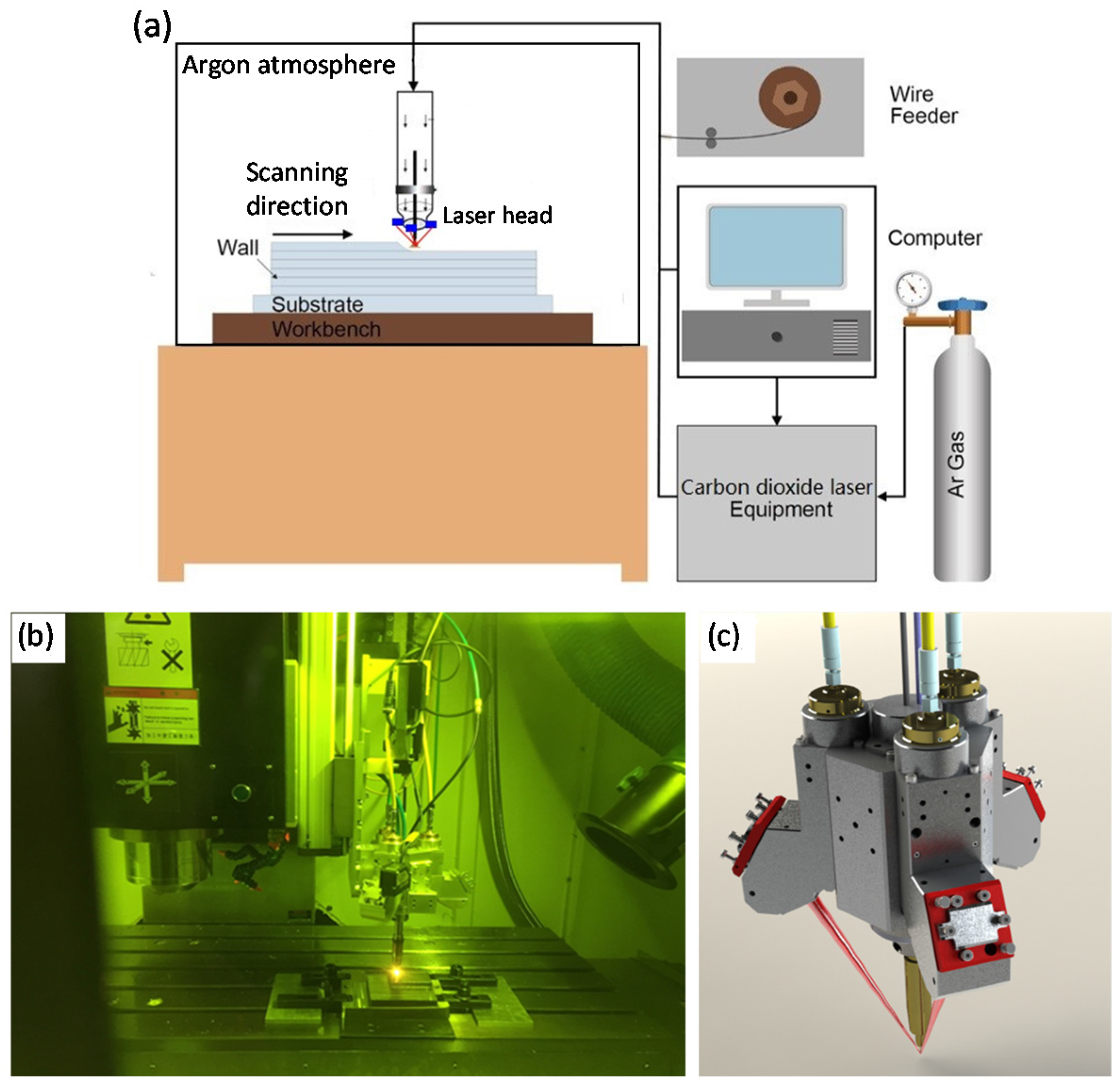
The LAM equipment is shown in Figure 3. The additive manufacturing device is mounted on the three-axis CNC machine (Shenyang Siasun Robot Automation Co., Ltd., Shenyang, China) which uses Simens 828D numerical control system (SIEMENS, Berlin, Germany) as shown in Figure 3a. The stroke of each axis is 1000 mm (X), 800 mm (Y) and 600 mm (Z), all of which are driven by servo motor (Shenyang Siasun Robot Automation Co., Ltd., Shenyang, China) and ball screw (Shenyang Siasun Robot Automation Co., Ltd., Shenyang, China).
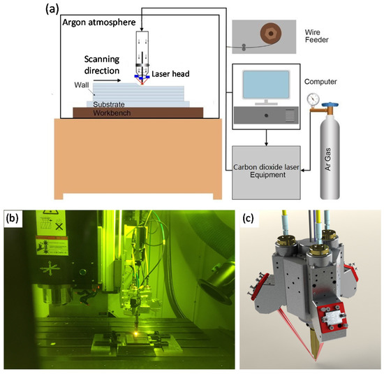
Figure 3.
(a) The schematic of the laser additive manufacturing equipment; (b) The equipment of vertical wire feeding with an axisymmetric multi-laser source; (c) the additive manufacturing device of vertical wire feeding.
The additive manufacturing device consists of four functional modules: laser focusing module, vertical wire feeding module, shielding gas module and water-cooling module as shown in Figure 3b. In the laser focusing module, three laser beams are focused onto the wire at a certain angle (in this paper, the angle between the wire and the laser beam is 55°). In vertical wire feeding module, the wire is fed vertically to the substrate. The additive manufacturing device driven by the actuator moves along the arranged path, thus the components can be formed. Argon gas is injected around the feeding wire to prevent metal oxidation at high temperatures. The water cooling module provides cooling to the laser head to ensure long-term stable operation. The operating temperature of the laser head is 10 to 25 °C.
Two components were fabricated in this experiment: one for the forming ability test and the other for the microstructural and mechanical properties tests. The shape of the component fabricated for the forming ability test consists of circles and polyline in all directions to test the forming ability and anisotropic forming problem of vertical wire feeding method. The tool-path of it is: first, scanning a circle with a diameter of 50 mm; second, scanning a twelve angle star which inscribed circle is 55 mm and circumcircle is 95 mm in diameter; third, scanning a circle with a diameter of 100 mm; finally, the additive manufacturing device is raised by 0.8 mm and repeat the first three steps.
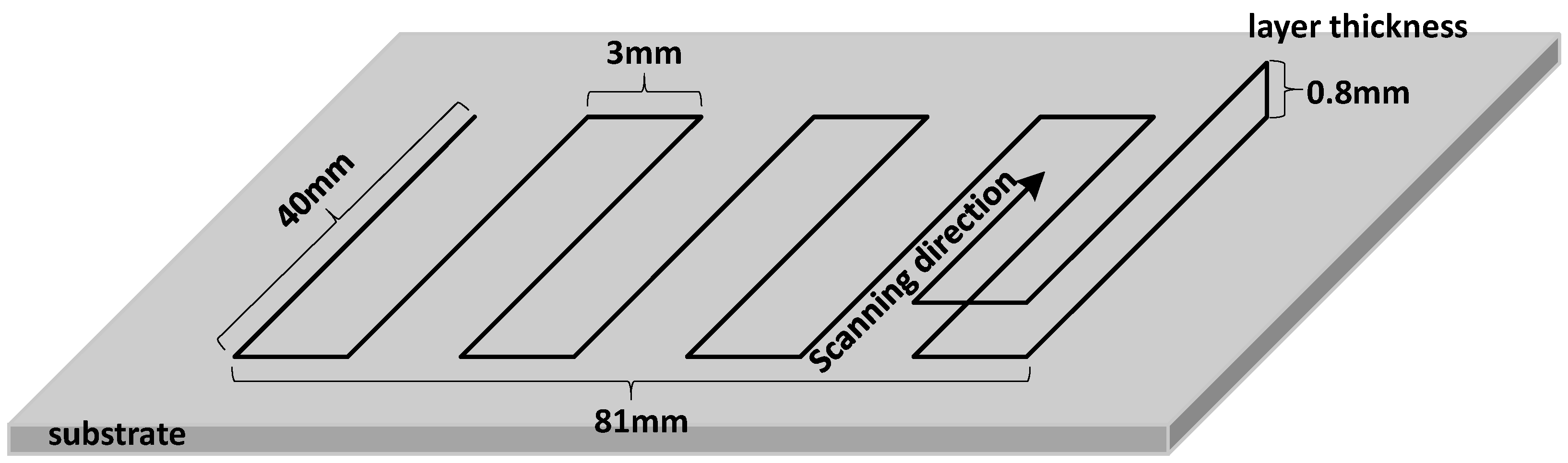
For convenience, a cuboid block with the size of 81 mm × 40 mm × 40 mm was fabricated for the microstructure observation and mechanical properties tests. The tool-path of the cuboid block is shown in Figure 4.

Figure 4.
The tool path of the cuboid sample block.
The components were fabricated on a Ti-6Al-4V titanium alloy substrate with the size of 150 mm × 150 mm × 5 mm. The process parameters used of the two components in the deposition process are given in Table 1.

Table 1.
Process parameters used in vertical wire feeding with an axisymmetric multi-laser source process.
2.2. Mechanical Characterization
The scanning direction (T direction) and building direction (L direction) of the block sample are shown in Figure 5a. Three tensile specimens were obtained from the middle of the block in each direction by wire-cutting techniques (Figure 5b,c). Static tensile tests at room temperature were carried out on an INSTRON 5966 material testing machine (INSTRON, Boston, MA, USA). The max load capacity of it is 10 kN and the drive type is powerful motors. The strain is acquired by video-extensometer (INSTRON, Boston, MA, USA). The cross-head displacement speed was 0.01 mm/s.
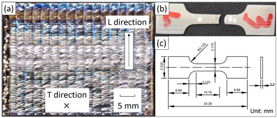
Figure 5.
(a) The block sample fabricated by vertical wire feeding with an axisymmetric multi-laser source; (b) tensile specimen obtained from the sample; (c) the dimensions of tensile specimens.
2.3. Microstructure and Morphology
The samples for microstructural and macrostructural characterization can be obtained from each direction. The samples were firstly polished with SiC paper (180, 360, 600, 1000, 2000), then etching for 20 s using a solution consisting of 2% HF (hydrofluoric acid) and 6% HNO3 (nitric acid). Light microscopy pictures were taken with a Leica DM4000M optical microscope (Leica Microsystems, Wechsler, Hesse, Germany). And macrostructural pictures were taken with a Canon DSLR Camera (NIKON CORPORATION, Tokyo, Japan). All the grains sizes were determined by ImageJ software (2.1.4.7, National Institutes of Health, Bethesda, MD, USA).
3. Results
3.1. Macrostructure
The component for the forming ability test is shown in Figure 6. It is obvious that the surface morphology of the circles was smooth and there was no difference in all directions. Moreover, the formation was steady in all the corners, where the surface morphology was smooth as well. The deposition process of the component was stable, as observed. Thereby, there was no anisotropic forming problem in vertical wire feeding with an axisymmetric multi-laser source process and it had a strong forming ability which can form the complex structure in a three-axis machine tool.
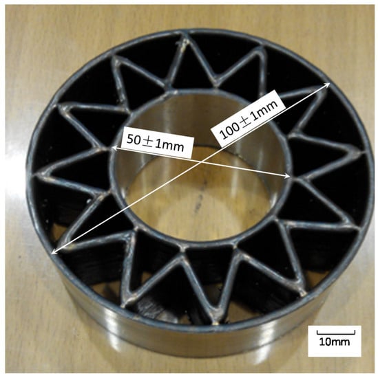
Figure 6.
The forming part fabricated by laser additive manufacturing with vertical wire feeding.
The surface of the sample block shows shiny areas where the molten pool was arranged like fish scales, as shown in Figure 5a. The size of the single track was about 5 mm in width and 0.8 mm in height under the present process parameters.
3.2. Grains
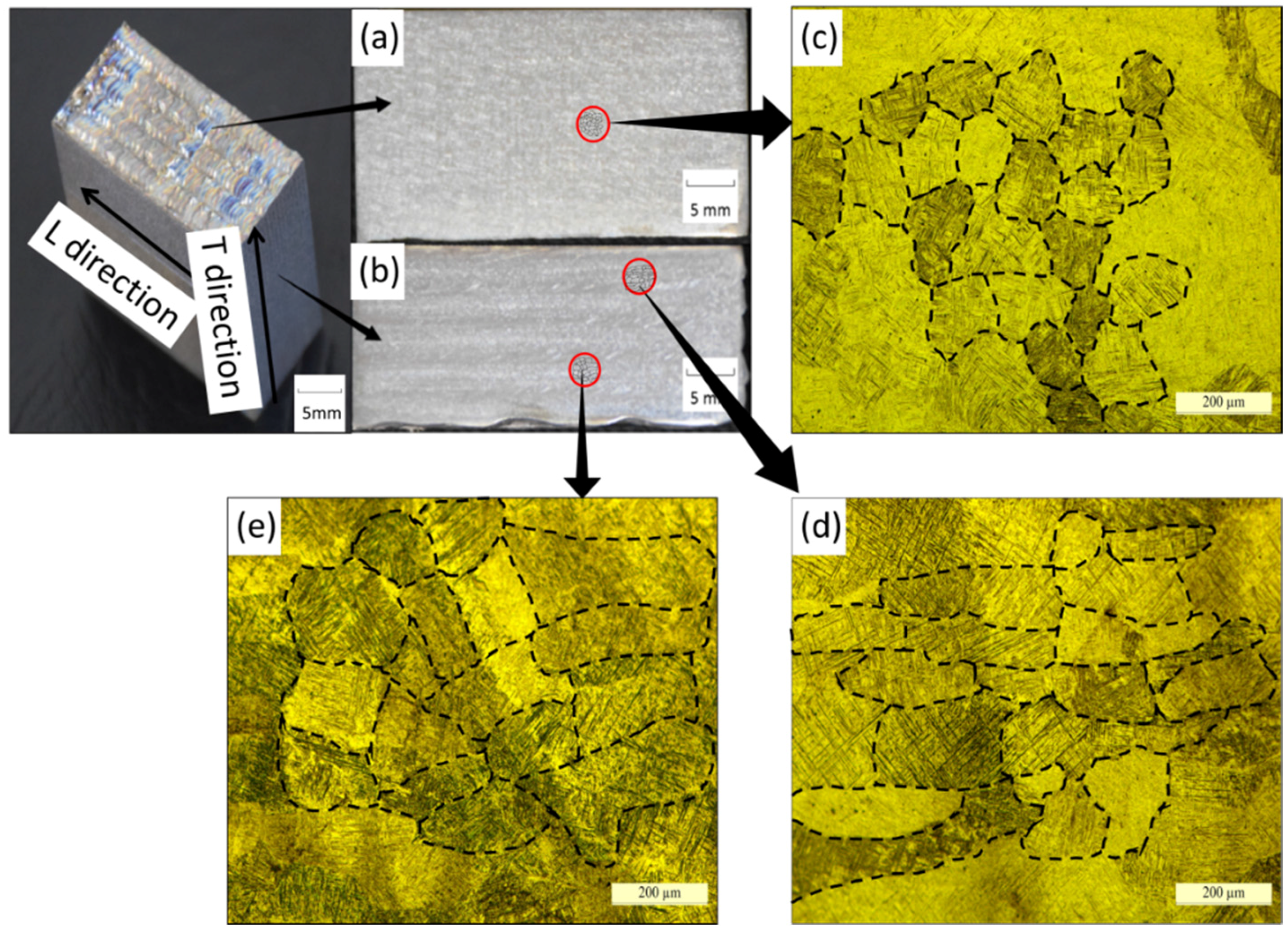
Figure 7 shows the macrostructures of the samples in the T (scanning direction) and L (building direction) directions. In the L direction, there were fine equiaxed grains evenly distributed with an average size of 81.5 μm, as shown in Figure 7a,c. In the T direction, most of the grains were equiaxed grains as well, but some columnar grains mixed with them, as shown in Figure 7b. The columnar grains were all short columnar grains (the aspect ratio of was less than five), as observed in Figure 7d; the average size of the short columnar grains was 338.6 μm in length and 122.5 μm in width. The average size of the equiaxed grains in the T direction was 101.9 μm (Figure 7e). A very important phenomenon could be observed as well: the position of the short columnar grains coincided with the moving path of the molten pool edge from one side to the other in the T direction, and the distance between the two parallel short columnar grains was 3 mm, which was the same as the deposit spacing.
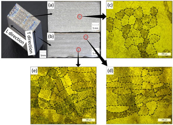
Figure 7.
Macrostructure of the fabricated samples: (a) all fine equiaxed grains evenly distributed in the L direction (building direction); (b) most of the grains in the T direction (scanning direction) are equiaxed grains and a small amount of short columnar grains (aspect ratio less than five) which are parallel to each other. Optical micrographs showing the microstructure of the fabricated samples: (c) equiaxed grains in the L direction; (d) short columnar grains and (e) equiaxed grains in the T direction.
3.3. Microstructure
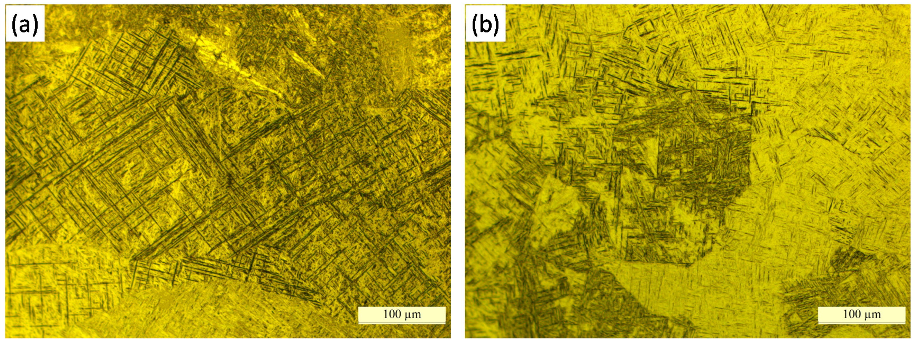
The microstructures of the sample in the two directions are shown in Figure 8 with a magnification of 500 times. The microstructures of the two directions exhibited martensite (α’) morphology (Figure 8a,b), which differs from the Ti-6Al-4V component fabricated by laser deposition with powders which exhibits a coarse α phase [21,22]. The martensite morphology proves that the cooling rate is faster compared with other AM process.
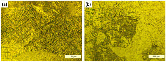
Figure 8.
Optical micrographs showing the microstructure of the fabricated samples in: (a) T direction; (b) L direction.
The diameters of the laser beams in References [9] and [21] were 4.7 mm and 5 mm, which means the size of the molten pool will be at least about 7 mm [9,21]. However, the size of the molten pool was smaller in this paper, about 5 mm; in this case, the heat can dissipate quickly. Moreover, the wire was inserted into the molten pool in the deposition process, which can take away part of the heat. Thereby, the cooling rate was faster in vertical wire feeding with an axisymmetric multi-laser source using the current process parameters, resulting in a martensite morphology.
3.4. Mechanical Properties
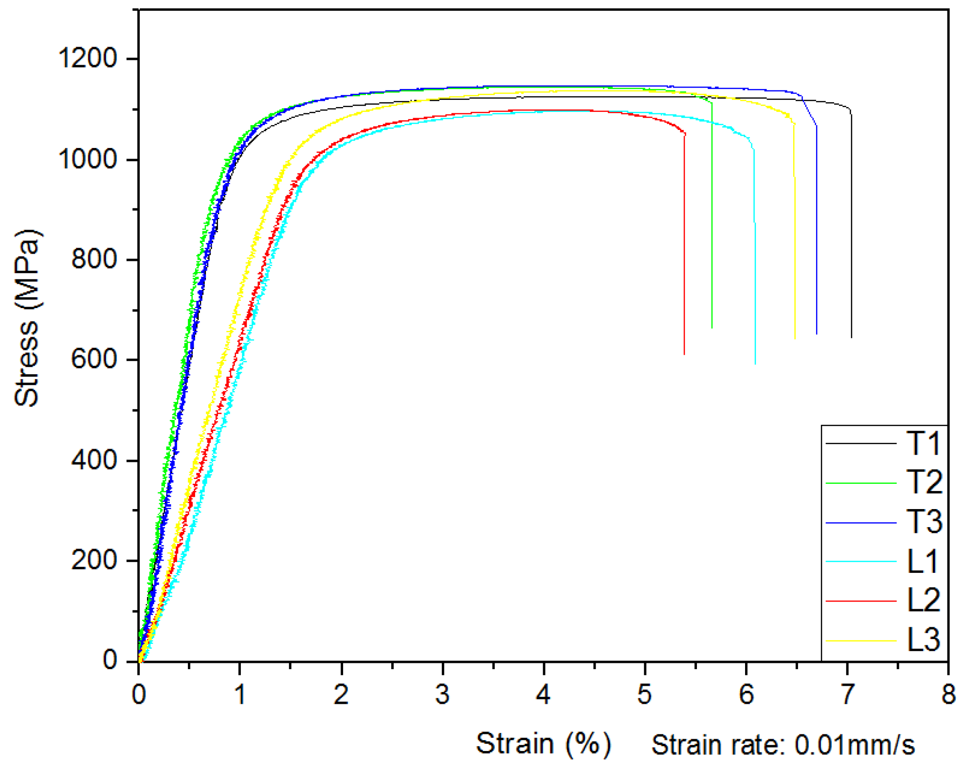
The results of the static tensile tests at room temperature are shown in Figure 9. The average ultimate tensile strength was 1140.33 MPa with the standard deviation of 11.59 in the T direction and 1114.67 MPa with the standard deviation of 20.81 in the L direction. However, the increase in the ultimate tensile strength resulted in a low strain (about 6%). The high strength and low ductility of the samples were mainly caused by the martensite.
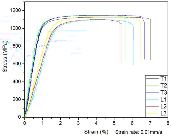
Figure 9.
Ultimate tensile strength and strain of the block sample fabricated by vertical wire feeding with an axisymmetric multi-laser source.
The components fabricated by LAM with paraxial wire feeding usually exhibit anisotropic mechanical properties in different directions which is caused by the development of coarse columnar grains [23,24].
Due to the large number of equiaxed grains, it is obvious that although the samples obtained from the T direction had a better strength and ductility than the samples obtained from the L direction, the difference between the two directions became smaller when compared with the components fabricated by the paraxial internal wire feeding method [9]. Therefore, the anisotropy problem of the mechanical properties has been greatly improved.
4. Discussion
It is observed that the sample block shows the novel grain morphology. All the columnar grains are short columnar grains, and the position of the short columnar grains coincides with the edge of the molten pool from one side to the other in the T direction. The distance between the regions where short columnar grains occur is the same as the track spacing. According to our knowledge, this phenomenon has never been found in LAM or other AM process. The explanation is as follows.
There are two dominant solidification mechanisms in the local molten pool during the LAM process, namely the heterogeneous nucleation on partially melted wire for equiaxed grains and the epitaxial growth from the pool bottom for columnar grains. The competition between them determines the component grain morphology [25]. The growth direction of the columnar grains is in the same direction as the temperature gradient in the molten pool. The high temperature gradients promote the growth of coarse columnar grains and make them grow throughout the sample [26].
In the vertical wire feeding process, the width of the molten pool was about 5 mm, and the diameter of the wire was 1.2 mm, which is nearly a quarter of the width of the molten pool. Therefore the wire can take away part of the heat flow, and the temperature gradient of the molten pool was disturbed in this way. When the wire was inserted into the molten pool during the deposition process, the wire could conduct a portion of the heat flow, as shown in Figure 10. The temperature guidance was disturbed, thus preventing the epitaxial growth of the columnar grains at the bottom. Hence, the heterogeneous nucleation on partially melted wire for equiaxed grains can be the main solidification mechanism in the molten pool, and it grows at the interface between the wire and the molten pool, resulting in the formation of Figure 10a.
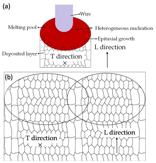
Figure 10.
(a) The schematic of the grain solidification in molten pool; (b) the schematic of the formation of grain morphology.
However, for the edge of the molten pool where the impact of the wire was small, a high temperature gradient still existed, leading to the formation of short columnar grains. Thereby, when the molten pool solidifies, short columnar grains will be formed on both sides of the molten pool and equiaxed grains will be formed in the middle. When the molten pool moves to the next track, remelting will occur, which makes the short columnar grains of the original molten pool remelt, contributing to the formation of equiaxed grains. New, short columnar grains will be formed at both sides of the molten pool, as shown in Figure 10b.
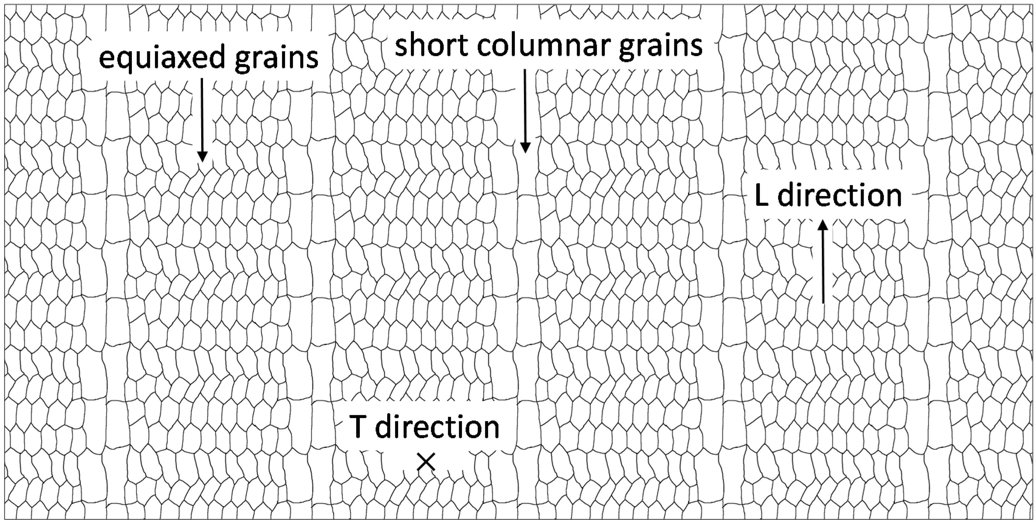
When the Ti-6Al-4V block is deposited layer by layer, the morphology (see Figure 11) appears at last. So the block sample shows the grain morphology (Figure 7), where short columnar grains are parallel to the building direction. That is the reason why the distance between the two parallel columnar grains is the same as the deposit spacing.

Figure 11.
The schematic of the grain morphology of the fabricated sample.
5. Conclusions
In this paper, the forming ability of LAM with coaxial wire feeding and the microstructure and mechanical properties of the fabricated component were investigated. Vertical wire feeding with an axisymmetric multi-laser source can eliminate the anisotropic forming problem in the deposition process. No matter whether the tool path is round or polyline, the forming morphology of the sample deposited by the vertical wire feeding method is smooth and there is no difference in all directions. A conclusion can be drawn that vertical wire feeding with an axisymmetric multi-laser source has a strong forming ability.
The samples fabricated by the vertical wire feeding method at the current process parameters exhibited fine equiaxed grains and some short columnar grains (parallel to each other). The average size of the equiaxed grains was about 91.7 μm. The average size of the short columnar grains was 339.6 μm in width and 122.5 μm in height. The microstructure of the samples exhibited fine basket-weave and martensite morphology.
The static tensile tests showed that the average strain of the samples was about 6%, and the average ultimate tensile strength of the L direction and T direction was 1140.33 MPa and 1114.67 MPa, respectively. The ultimate tensile strength difference of the two directions (L and T) becomes smaller. Therefore, vertical wire feeding with an axisymmetric multi-laser source at the current process parameters can improve the ultimate tensile strength, and the anisotropy of the mechanical properties of the fabricated parts can be largely eliminated.
Acknowledgments
This research is supported by the National Natural Science Foundation of China (No. 51405018), the Discipline Group Innovation Collaboration Project of China Association for Science and Technology (No. 2016XKYL05), Fundamental research of the State Ministry (No. JCKY2016602B007) and the Excellent Young Scholars Research Fund of the Beijing Institute of Technology (No. 2016CX04026). The authors would like to thank the anonymous reviewers for their helpful comments and suggestions to improve the quality of this paper.
Author Contributions
Jie Fu, Lin Gong, Yifei Zhang conceived and designed the experiments; Junchao Chang and Yifei Zhang performed the experiments; Lin Gong and Xuezhi Shi analyzed the data; Jiping Lu contributed reagents/materials/analysis tools; Jie Fu, Lin Gong and Qianru Wu wrote the paper.
Conflicts of Interest
The authors declare no conflict of interest.
References
- Peters, M.; Kumpfert, J.; Ward, C.H.; Leyens, C. Titanium alloys for aerospace applications. Adv. Eng. Mater. 2003, 5, 419–427. [Google Scholar] [CrossRef]
- Rawal, S.; Brantley, J.; Karabudak, N. Additive manufacturing of Ti-6Al-4V alloy components for spacecraft applications. In Proceedings of the International Conference on Recent Advances in Space Technologies, Istanbul, Turkey, 12–14 June 2013; pp. 5–11.
- Peters, M.; Hemptenmacher, J.; Kumpfert, J.; Leyens, C. Titan und titanlegierungen: Struktur, gefüge, eigenschaften. In Titan und Titanlegierungen; Wiley-VCH: Weinheim, Germany, 2002; pp. 1–37. [Google Scholar]
- Zhang, M.; Liu, C.; Shi, X.; Chen, X.; Chen, C.; Zuo, J.; Lu, J.; Ma, S. Residual stress, defects and grain morphology of Ti-6AL-4V alloy produced by ultrasonic impact treatment assisted selective laser melting. Appl. Sci. 2016, 6, 304. [Google Scholar] [CrossRef]
- Shi, X.; Ma, S.; Liu, C.; Chen, C.; Wu, Q.; Chen, X.; Lu, J. Performance of high layer thickness in selective laser melting of Ti-6Al-4V. Materials 2016, 9, 975. [Google Scholar] [CrossRef]
- Ravi, G.A.; Qiu, C.; Attallah, M.M. Microstructural control in a Ti-based alloy by changing laser processing mode and power during direct laser deposition. Mater. Lett. 2016, 179, 104–108. [Google Scholar] [CrossRef]
- Hong, M.-H.; Min, B.K.; Kwon, T.-Y. The influence of process parameters on the surface roughness of a 3D-printed Co–Cr dental alloy produced via selective laser melting. Appl. Sci. 2016, 6, 401. [Google Scholar] [CrossRef]
- Liu, C.M.; Tian, X.J.; Tang, H.B.; Wang, H.M. Microstructural characterization of laser melting deposited Ti–5AL-5Mo–5V–1Cr–1Fe near β titanium alloy. J. Alloys Compd. 2013, 572, 17–24. [Google Scholar] [CrossRef]
- Brandl, E.; Palm, F.; Michailov, V.; Viehweger, B.; Leyens, C. Mechanical properties of additive manufactured titanium (Ti-6Al-4V) blocks deposited by a solid-state laser and wire. Mater. Des. 2011, 32, 4665–4675. [Google Scholar] [CrossRef]
- Ader, C.; Brosemer, M.; Freyer, C.; Fricke, H.; Hennigs, D.; Klocke, F.; Kühne, V.; Meiners, W.; Over, C.; Pleteit, H. Research on layer manufacturing techniques at fraunhofer. In Proceedings of the Solid Freeform Fabrication Symposium 2004, Austin, TX, USA, 2–4 August 2004; pp. 26–37.
- Santos, E.C.; Shiomi, M.; Osakada, K.; Laoui, T. Rapid manufacturing of metal components by laser forming. Int. J. Mac. Tools Manuf. 2006, 46, 1459–1468. [Google Scholar] [CrossRef]
- Martina, F.; Colegrove, P.A.; Williams, S.W.; Meyer, J. Microstructure of interpass rolled wire + arc additive manufacturing Ti-6Al-4V components. Metall. Mater. Trans. A 2015, 46, 6103–6118. [Google Scholar] [CrossRef]
- Brandl, E.; Schoberth, A.; Leyens, C. Morphology, microstructure, and hardness of titanium (Ti-6Al-4V) blocks deposited by wire-feed additive layer manufacturing (ALM). Mater. Sci. Eng. A 2012, 532, 295–307. [Google Scholar] [CrossRef]
- Baufeld, B.; Biest, O.V.D.; Gault, R. Additive manufacturing of Ti–6AL–4V components by shaped metal deposition: Microstructure and mechanical properties. Mater. Des. 2010, 31, S106–S111. [Google Scholar] [CrossRef]
- Lopes, G.; Miranda, R.; Quintino, L.; Rodrigues, J. Additive manufacturing of Ti-6Al-4V based components with high power fiber lasers. In Virtual and Rapid Manufacturing; Tailor & Francis Group: London, UK, 2008; pp. 369–374. [Google Scholar]
- Shi, X.; Ma, S.; Liu, C.; Wu, Q.; Lu, J.; Liu, Y.; Shi, W. Selective laser melting-wire arc additive manufacturing hybrid fabrication of Ti-6Al-4V alloy: Microstructure and mechanical properties. Mater. Sci. Eng. A 2017, 684, 196–204. [Google Scholar] [CrossRef]
- Wang, Y.K.; Shi, S.H.; Fu, G.Y.; Li, C.S. Research on the key process parameters in direct laser deposition using coaxial inside-beam wire feeding. Appl. Mech. Mater. 2010, 43, 401–404. [Google Scholar] [CrossRef]
- Kim, J.D.; Peng, Y. Plunging method for ND: YAG laser cladding with wire feeding. Opt. Lasers Eng. 2000, 33, 299–309. [Google Scholar] [CrossRef]
- Sui, H.M.; Bi, G.; Folkes, J.; Pashby, I. Deposition of Ti–6AL–4V using a high power diode laser and wire, part I: Investigation on the process characteristics. Surf. Coat. Technol. 2008, 202, 3933–3939. [Google Scholar]
- Syed, W.U.H.; Li, L. Effects of wire feeding direction and location in multiple layer diode laser direct metal deposition. Appl. Surf. Sci. 2005, 248, 518–524. [Google Scholar] [CrossRef]
- Lu, Y.; Tang, H.B.; Fang, Y.L.; Liu, D.; Wang, H.M. Microstructure evolution of sub-critical annealed laser deposited Ti–6AL–4V alloy. Mater. Des. 2012, 37, 56–63. [Google Scholar] [CrossRef]
- Kelly, S.M.; Kampe, S.L. Microstructural evolution in laser-deposited multilayer Ti-6Al-4V builds: Part I. Microstructural characterization. Metall. Mater. Trans. A 2004, 35, 1861–1867. [Google Scholar] [CrossRef]
- Qiu, C.; Adkins, N.J.E.; Attallah, M.M. Selective laser melting of invar 36: Microstructure and properties. Acta Mater. 2015, 103, 382–395. [Google Scholar] [CrossRef]
- Simonelli, M.; Tse, Y.Y.; Tuck, C. Effect of the build orientation on the mechanical properties and fracture modes of slm Ti–6AL–4V. Mater. Sci. Eng. A 2014, 616, 1–11. [Google Scholar] [CrossRef]
- Wang, T.; Zhu, Y.Y.; Zhang, S.Q.; Tang, H.B.; Wang, H.M. Grain morphology evolution behavior of titanium alloy components during laser melting deposition additive manufacturing. J. Alloys Compd. 2015, 632, 505–513. [Google Scholar] [CrossRef]
- Fu, H.; Guo, J.; Liu, L.; Li, J. Directional Solidification and Processing of Advanced Materials; The Science Press: Beijing, China, 2008; p. 498. [Google Scholar]


© 2017 by the authors. Licensee MDPI, Basel, Switzerland. This article is an open access article distributed under the terms and conditions of the Creative Commons Attribution (CC BY) license ( http://creativecommons.org/licenses/by/4.0/).