Featured Application
The method employing the artificial neural network proposed in this study for predicting the material removal rate in ultrasonic machining can be considered as a guide for modelling complex general machining problems without explicit mathematical functions.
Abstract
The present study proposes a back propagation artificial neural network (BPANN) to provide improved precision for predicting the material removal rate (MRR) in ultrasonic machining. The BPANN benefits from the advantage of artificial neural networks (ANNs) in dealing with complex input-output relationships without explicit mathematical functions. In our previous study, a conventional linear regression model and improved nonlinear regression model were established for modelling the MRR in ultrasonic machining to reflect the influence of machining parameters on process response. In the present work, we quantitatively compare the prediction precision obtained by the previously proposed regression models and the presently proposed BPANN model. The results of detailed analyses indicate that the BPANN model provided the highest prediction precision of the three models considered. The present work makes a positive contribution to expanding the applications of ANNs and can be considered as a guide for modelling complex problems of general machining.
1. Introduction
Artificial neural networks (ANNs) represent an approach for solving complex problems in numerous fields and are particularly useful for dealing with complex input-output relationships without explicit mathematical functions [1]. ANNs simulate the human brain to process information rapidly and efficiently through a system of neural networks consisting of vast numbers of neurons. ANNs usually consist of an input layer, an output layer and one or more hidden layers. In general, the number of neurons of the input layer must correspond to the number of input variables; the number of neurons of the output layer must be equivalent to the number of outputs produced by the network; and the hidden layer performs the operations designed to achieve the desired output, where its number of neurons is obtained by a process of trial and error [1,2]. The development of the ANN computing paradigm has been mainly driven by the practical requirement to solve specific problems in a rapid and more computationally-efficient manner. The ability to learn is a peculiar feature of intelligent systems. In artificial systems, learning is viewed as the process of updating the internal representation of a system in response to external stimuli so that it can perform a specific task with greater precision and efficiency. The learning process in ANNs includes modifying the network architecture, which involves incrementally adjusting the magnitudes of the weights of the connections between neurons in the network (also known as the “synapse strength”) [2,3]. This process is performed repetitively as the network is presented with training examples, which is similar to the process by which biological organisms learn from experience. As a result, ANNs have been one of the most powerful statistical approaches for solving problems that are not amenable to conventional statistical methods [3].
In contrast to the modelling of input-output relationships using ANN techniques, regression models provide a quantitative description of input-output relationships using specific mathematical functions. For the ultrasonic machining (USM) technique, process responses are associated with the selection of machining parameters [4,5,6,7]. An increased material removal rate (MRR) has always been one of the primary goals of USM manufacturers and users [8,9,10,11,12]. A number of methods have been developed for selecting machining parameter values to enhance the MRR, such as Taguchi statistical analyses and regression modelling analyses [13,14,15,16,17,18,19]. In our past work [5], we analysed the MRR of USM in detail based on orthogonal tests using the Taguchi method. The regression modelling analyses employed three main machining parameters affecting the process response (i.e., abrasive granularity, feed pressure and feed speed). Analysis of variance (ANOVA) was executed to investigate the statistical significance of the parameters at a 95% confidence level and to determine the relative contribution of the parameters to the process response. The results showed that the abrasive granularity had a significant and nonlinear effect on the MRR in USM, where an abrasive granularity deviating substantially from an optimum value negatively affected the MRR. On this basis, an improved nonlinear regression model was established using a mathematical modelling method. The prediction precision of the improved nonlinear regression model was demonstrated to be substantially greater than that of a conventional linear regression model. However, identifying an appropriate function for fitting the nonlinear relationships between the machining parameters of USM and the process response is typically quite difficult. Therefore, this approach requires much more powerful modelling methods that can facilitate mapping between machining parameters and process responses.
For this reason, ANNs have been applied for complex input-output modelling and have nearly always improved the correlations obtained relative to conventional regression methods [20,21]. The ANN models employed for this purpose have been denoted by various terms such as connectionist models, parallel distributed processing models and neuromorphic systems [3]. These models function by means of the dense interconnection of simple computational units and are specified by the network topology, computational unit characteristics and training or learning algorithms employed [1]. The advantages of ANNs have facilitated numerous successful applications [22,23].
In addition to our previously proposed regression models [5], we have also applied ANNs [24,25,26] to explore the impact of machining parameters on USM process responses. Employing ANNs for predicting the MMR in USM offers a significant advantage over regression techniques because ANNs do not require explicit mathematical functions. However, we did not consider whether the prediction precision provided by ANN modelling approaches is greater than that of our regression models. Therefore, the primary objective of this study is to propose a back propagation ANN (BPANN) for dealing with the complex input-output relationships in USM in the absence of an explicit mathematical model. We then compare the prediction precision of the BPANN proposed in this study with the corresponding precisions obtained using the previously proposed regression models [5] with equivalent experimental parameters on an experimental apparatus. As such, the neurons of the input layer were selected as the abrasive granularity (G), feed pressure (P) and feed speed (FS) and included a single neuron in the output layer representative of the predicted MRR, which is consistent with past studies [5].
2. Review of Our Earlier Research Work
Table 1 presents the main aspects and results of our earlier research work regarding regression models [5].

Table 1.
Main details and results of our earlier research work regarding regression models [5].
According to Table 1, we note that the establishment of a suitable nonlinear regression equation is crucial to use in the regression technique for predicting the MRR in the USM technique. However, establishing a suitable nonlinear regression equation is difficult for most complex input-output problems of general machining. In contrast, the input values of ANNs can theoretically be arbitrary because the output values of ANNs are obtained by simulating the human learning process. Therefore, we consider an ANN as a more powerful modelling method for mapping complex nonlinear input-output problems.
3. Neural Network Modelling Method
The proposed BPANN is an iterative gradient procedure designed to minimize the mean square error (MSE) between the actual output of the model and the desired output. Similar ANNs have already been used in many fields such as data modelling, classification, prediction, control, data and image compression and pattern recognition [3].
The proposed BPANN model was based on a total of 96 group experiments, which included 80 group experiments conducted in this study and 16 group experiments conducted in our previous study [5]. Supervised learning was selected as the training method for the BPANN [20,21,22,23]. To facilitate comparison between the BPANN model obtained in this study and our previously proposed regression models, the data obtained from the 80 group experiments were randomly divided into two subgroups consisting of 60 and 20 experimental datasets for conducting training and validation, respectively, and the 16 group experiments were employed as testing sets.
The transfer function employed for the network is given as follows:
where x is the input value of the neuron and f(x) is the output of the neuron. This function is a hyperbolic tangent sigmoid, which is mathematically equivalent to a hyperbolic tangent function, but which provides for improved network functionality [20,24]. All variable values were normalized within the interval (0, 1) to improve the effectiveness of the transfer function. While numerous methods are available for normalizing variable values, the present work employed the following equation [20,24]:
where Xi is the normalized element of any input value xi and xmax and xmin are the maximum and minimum values of xi, respectively.
The BPANN was trained using resilient backpropagation, which considerably improves the results of the training process for networks employing sigmoid transfer functions [22,23]. The learning rate used was 0.01. The BPANN was constructed, trained and implemented using MATLAB 7.11.0 (R2010b) software, and statistical analyses were conducted using SPSS 20.0 software, all of which were run under a Microsoft Windows 7 operating system on a computer with an Intel® Core™ i3-470 CPU. Overfitting is often the main problem associated with the training of ANNs [20,21]. To avoid overfitting of the BPANN, the point at which overfitting occurred was detected by conducting a comparison of the training and validation set errors every 100 epochs to determine when an increase in the validation set error occurred in conjunction with a decrease in the training set error. In addition, a specific search program comprising a series of loops, one in each sublayer, was proposed to obtain the optimum structure of the BPANN [20,21]. The number of neurons in each sub-layer was then successively increased automatically during training. Numerous methods can be employed to evaluate the performance of a model. The simplest method is based on the value of the correlation coefficient R for a plot of predicted value versus experimental output [1]. When all the loops have finished, the program considers the optimum structure to be that obtaining an absolute value of R that is closest to one for the validation set [20,21], where |R| = 1 corresponds to perfect correlation. In addition, the determination coefficient R2 is another important value for evaluating the performance of a model, where an R2 value closest to one implies an optimum model.
4. Results and Discussion
The topological structure of the BPANN obtained in this study is presented in Figure 1, where the number of input layer neurons is three, representing G, P and FS, the number of output layer neurons is one, representing the MRR, and the optimum number of neurons in the single hidden layer is 10, which was obtained according to a trial and error process. The learning process of the BPANN is presented in Table A1 of Appendix A. The error training curve is presented in Figure A1 of Appendix B.
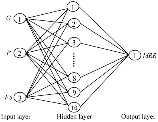
Figure 1.
Structure of the BPANN obtained (3 × 10 × 1).
A linear least-squares fit [18] was adopted to compare the prediction precisions of the previously proposed regression models and the presently proposed BPANN model. The order of the linear fit was determined by inspecting the residual errors of the approximation via the MSE [27,28].
According to our past study [5], the conventional linear regression equation is given as follows:
The improved nonlinear regression equation is given as follows:
The best linear fits of the MRR predictions obtained for the conventional linear regression model, improved nonlinear regression model and the testing sets of the BPANN model with respect to the experimental values are presented in Figure 2a–c, respectively.
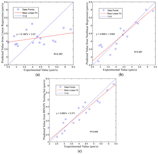
Figure 2.
Correlation between the predicted values and the experimental values along with the best linear fit to the data: (a) the conventional linear regression model; (b) the improved nonlinear regression model; and (c) the BPANN model.
The modelling performances, i.e., the slope M, intercept B, R and R2, of the three methods are presented in Table 2, where the ideal values are M = 1, B = 0, R = 1 and R2 = 1. Here, the prediction precision increases as the obtained values approach the ideal values.
Table 2.
Prediction precision indicators of the three modelling methods, where the ideal values are M = 1, B = 0, R = 1 and R2 = 1.
From Figure 2 and Table 2, we note that the BPANN model has the highest prediction precision of all models considered. This indicates that the BPANN model provides better prediction results than either of the regression models.
To intuitively demonstrate the prediction precision obtained by the three models, the experimentally measured values and the corresponding prediction values for the sixteen experimental datasets are presented in Figure 3. We observe that the BPANN model and the improved nonlinear regression model are useful for predicting the MRR in the USM process; however, the results in Figure 2 and Table 2 more clearly demonstrate that the BPANN model provides the best results. Meanwhile, the conventional linear regression model is useless for predicting the MRR in the USM process.
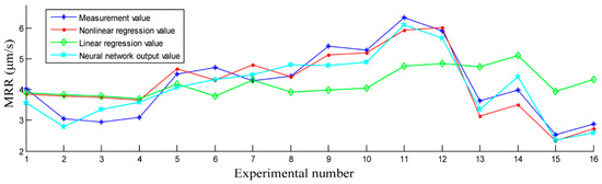
Figure 3.
Comparison of measured MRR values and the corresponding prediction values of the three models for the sixteen experimental datasets.
5. Conclusions
The present study proposed the BPANN for dealing with the complex input-output relationships in USM in the absence of an explicit mathematical model. We then compared the MRR prediction precision of the BPANN with the corresponding precisions obtained using previously proposed regression techniques with equivalent experimental parameters G, P and FS. Based on the conducted analyses, the following conclusions can be drawn.
- (1)
- The BPANN model proposed in this study and the improved nonlinear regression model established in our earlier research are useful for predicting the MRR in the USM process, but the results of the present study demonstrate that the BPANN model provides the best results and requires no explicit mathematical function.
- (2)
- The method employing ANNs proposed in this study for predicting the MRR in USM can be considered as a guide for modelling complex general machining problems without explicit mathematical functions.
Acknowledgments
This research was financially supported by the research projects: the Research Plan of Nanjing Agricultural University of China (No. 2015G01) and the Research Plan of State Key Laboratory for Manufacturing Systems Engineering at Xi’an Jiao tong University of China (No. sklms2017008).
Author Contributions
Gaoyan Zhong designed and performed the experiments, analysed the data and drafted the present report. Min Kang contributed the experimental materials and analysis tools. Shoufeng Yang proposed the method of ANN modelling.
Conflicts of Interest
The authors declare no conflict of interest. The founding sponsors had no role in the design of the study; in the collection, analyses or interpretation of data; in the writing of the manuscript; nor in the decision to publish the results.
Appendix A
Table A1.
Learning process of the BPANN.
Appendix B
The training function of the BPANN proposed in this study was “trainlm”, and the learning function was “learngdm”. The learning rate was 0.1; the error training target was 0.001; and the target number of training steps was 500. The BPANN system reached the training requirements after 269 iterations. The error training curve is presented in Figure A1.

Figure A1.
Error training curve.

References
- Zhang, Y.M.; Yang, S.; Evans, J.R.G. Revisiting Hume-Rothery’s Rules with artificial neural networks. Acta Mater. 2008, 56, 1094–1105. [Google Scholar] [CrossRef]
- Akhlaghi, F.; Khakbiz, M.; Rezaii Bazazz, A. Evolution of the size distribution of Al–B4C nano-composite powders during mechanical milling: A comparison of experimental results with artificial neural networks and multiple linear regression models. Neural Comput. Appl. 2017, 6, 1–10. [Google Scholar] [CrossRef]
- Zhang, Y. Applications of Artificial Neural Networks (ANNs) in Several Different Materials Research Fields; Queen Mary, University of London: London, UK, 2010. [Google Scholar]
- Bhosale, S.B.; Pawade, R.S.; Brahmankar, P.K. Effect of process parameters on MRR, TWR and surface topography in ultrasonic machining of alumina-zirconia ceramic composite. Ceram. Int. 2014, 40, 12831–12836. [Google Scholar] [CrossRef]
- Zhong, G.; Xu, J.; Wu, Y.; Yang, S. Statistical Analyses and Regression Modeling for Influence of Process Parameters on Material Removal Rate in Ultrasonic Machining. Glob. J. Technol. Optim. 2015, 6, 1–6. [Google Scholar]
- Nath, C.; Lim, G.C.; Zheng, H.Y. Influence of the material removal mechanisms on hole integrity in ultrasonic machining of structural ceramics. Ultrasonics 2012, 52, 605–613. [Google Scholar] [CrossRef] [PubMed]
- Ahmed, N.; Abdo1, B.M.; Darwish, S.; Moiduddin, K.; Pervaiz, S.; Alahmari, A.M.; Naveed, M. Electron beam melting of titanium alloy and surface finish improvement through rotary ultrasonic machining. Int. J. Adv. Manuf. Technol. 2017, 4, 1–13. [Google Scholar] [CrossRef]
- Jüschke, M.; Koch, C. Model processes and cavitation indicators for a quantitative description of an ultrasonic cleaning vessel: Part I: Experimental results. Ultrason. Sonochem. 2012, 19, 787–795. [Google Scholar] [CrossRef] [PubMed]
- Abhishek, R.K.; Datta, S.; Biswa, B.; Mahapatra, S. Machining performance optimization for electro-discharge machining of Inconel 601, 625, 718 and 825: An integrated optimization route combining satisfaction function, fuzzy inference system and Taguchi approach. J. Braz. Soc. Mech. Sci. Eng. 2017, 39, 3499–3527. [Google Scholar]
- Thoe, T.B.; Aspinwall, D.K.; Wise, M.L.H. Review on ultrasonic machining. Int. J. Mach. Tools Manuf. 1998, 38, 239–255. [Google Scholar] [CrossRef]
- Xu, J. Multi-Objective Optimization Research of Precision Turning Process Parameters; Nanjing Agricultural University: Nanjing, China, 2016. [Google Scholar]
- Singh, R.; Khamba, J.S. Investigation for ultrasonic machining of titanium and its alloys. J. Mater. Process. Technol. 2007, 183, 363–367. [Google Scholar] [CrossRef]
- Kasman, S. Impact of parameters on the process response: A Taguchi orthogonal analysis for laser engraving. Measurement 2013, 46, 2577–2584. [Google Scholar] [CrossRef]
- Kivak, T.; Samtas, G.; Cicek, A. Taguchi method based optimisation of drilling parameters in drilling of AISI 316 steel with PVD monolayer and multilayer coated HSS drills. Measurement 2012, 45, 1547–1557. [Google Scholar] [CrossRef]
- Siddiquee, A.N.; Khan, Z.A.; Goel, P. Mukesh Kumar, Gaurav Agarwal, Noor Zaman Khan, Optimization of Deep Drilling Process Parameters of AISI 321 Steel using Taguchi Method. Procedia Mater. Sci. 2014, 6, 1217–1225. [Google Scholar] [CrossRef]
- Zhong, G. Ternary Regression Modeling Analysis of NC Ultrasonic Machining Efficiency. Appl. Mech. Mater. 2010, 37–38, 1388–1392. [Google Scholar] [CrossRef]
- Asilturk, I.; Akkus, H. Determining the effect of cutting parameters on surface roughness in hard turning using the Taguchi method. Measurement 2011, 44, 1697–1704. [Google Scholar] [CrossRef]
- Zhong, G.; Vaezi, M.; Liu, P.; Pan, L.; Yang, S. Characterization approach on the extrusion process of bioceramics for the 3D printing of bone tissue engineering scaffolds. Ceram. Int. 2017, 43, 13860–13868. [Google Scholar] [CrossRef]
- Liu, Y.; Yang, Y.; Wang, D. Investigation into the shrinkage in Z-direction of components manufactured by selective laser melting (SLM). Int. J. Adv. Manuf. Technol. 2017, 90, 2913–2923. [Google Scholar] [CrossRef]
- Esteban, L.G.; Fernández, F.G.; de Palacios, P. MOE prediction in Abies pinsapo Boiss. timber: Application of an artificial neural network using non-destructive testing. Comput. Struct. 2009, 87, 1360–1365. [Google Scholar] [CrossRef]
- García-Iruela, A.; Fernandez, F.G.; Esteban, L.G.; de Palacios, P.; Simon, C.; Arriaga, F. Comparison of modelling using regression techniques and an artificial neural network for obtaining the static modulus of elasticity of Pinus radiata D. Don. timber by ultrasound. Compos. Part B 2016, 96, 112–118. [Google Scholar] [CrossRef]
- Valls, J.M.; Galvan, I.M.; Isasi, P. Lazy learning in radial basis neural networks: A way of achieving more accurate models. Neural Process. Lett. 2004, 20, 105–124. [Google Scholar] [CrossRef]
- Gaja, H.; Liou, F. Defect classification of laser metal deposition using logistic regression and artificial neural networks for pattern recognition. Int. J. Adv. Manuf. Technol. 2017, 8, 1–12. [Google Scholar] [CrossRef]
- Zhong, G.; Wang, Y. NC Ultrasonic Machining Efficiency: Neural Network-Based Modeling and Simulation. Adv. Mater. Res. 2011, 291, 406–410. [Google Scholar] [CrossRef]
- Zhong, G.; Kang, M. Modeling and Simulation for Effect in Numerical Controlled Ultrasonic Machining Based on Artificial Neural Network. China Acad. J. Syst. Simul. 2007, 19, 1620–1623. [Google Scholar]
- Zhong, G.; Kang, M. Performance Analysis on Numerical Controlled Ultrasonic Machining Based on BP Artificial Neural Network. China Acad. J. Electromach. Mould 2007, 4, 37–40. [Google Scholar]
- Zhong, G.; Wang, C.; Yang, S.; Zheng, E.; Ge, Y. Position geometric error modeling, identification and compensation for large 5-axis machining center prototype. Int. J. Mach. Tools Manuf. 2015, 89, 142–150. [Google Scholar] [CrossRef]
- Lee, J.H.; Liu, Y.; Yang, S.-H. Accuracy improvement of miniaturized machine tool: Geometric error modeling and compensation. Int. J. Mach. Tools Manuf. 2006, 46, 1508–1516. [Google Scholar] [CrossRef]


© 2017 by the authors. Licensee MDPI, Basel, Switzerland. This article is an open access article distributed under the terms and conditions of the Creative Commons Attribution (CC BY) license (http://creativecommons.org/licenses/by/4.0/).