Modeling and Dynamic Analysis on the Direct Operating Solenoid Valve for Improving the Performance of the Shifting Control System
Abstract
:1. Introduction
2. Valve Structure and Principle
3. Modeling
3.1. Electro-Magnetic Subsystem
3.2. Hydraulic Subsystem
3.3. Dynamics Motion
3.4. The Simulation Model
3.5. Validation of Model
4. Results and Discussion
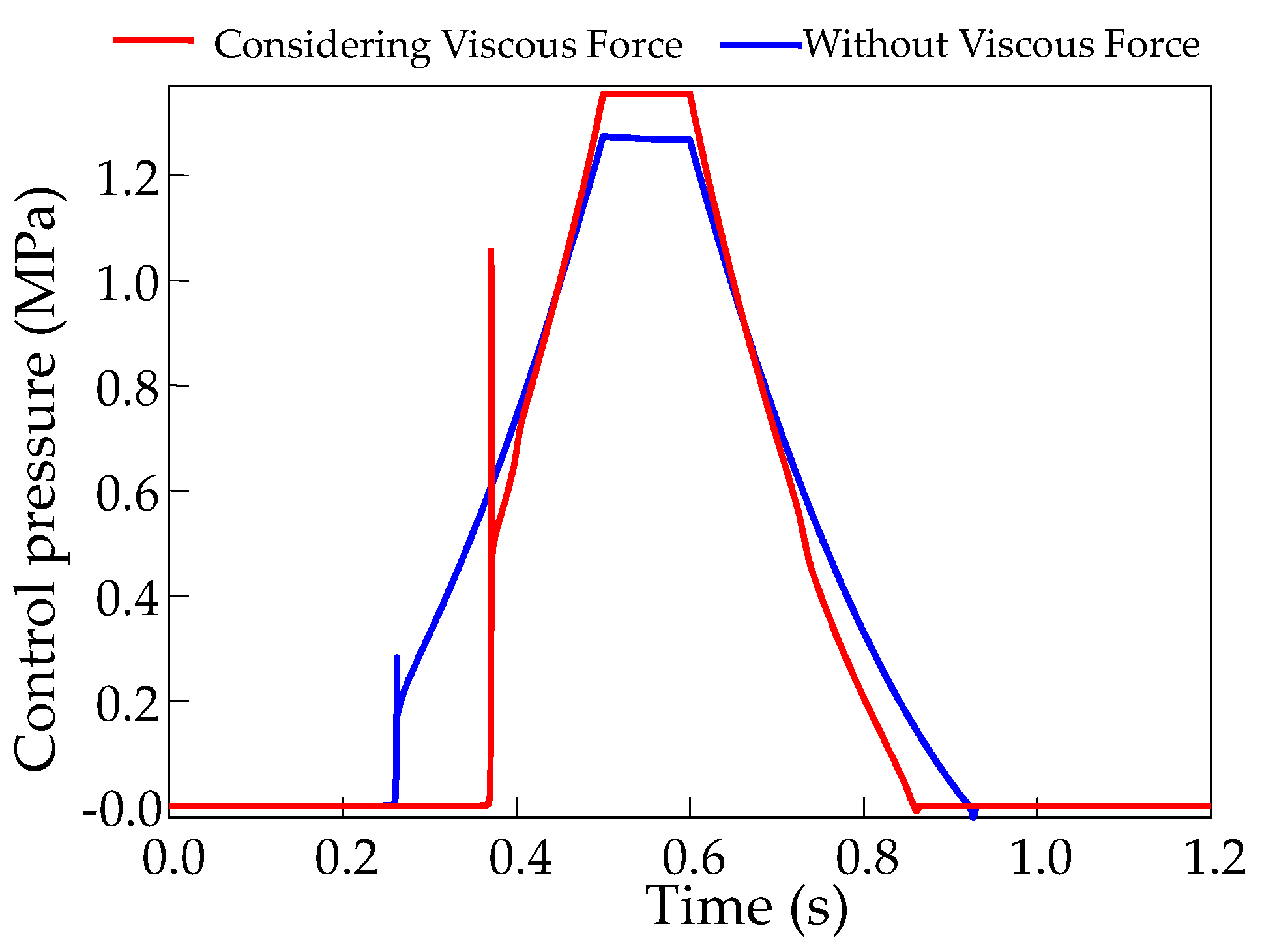
4.1. Analysis of Pressure Response
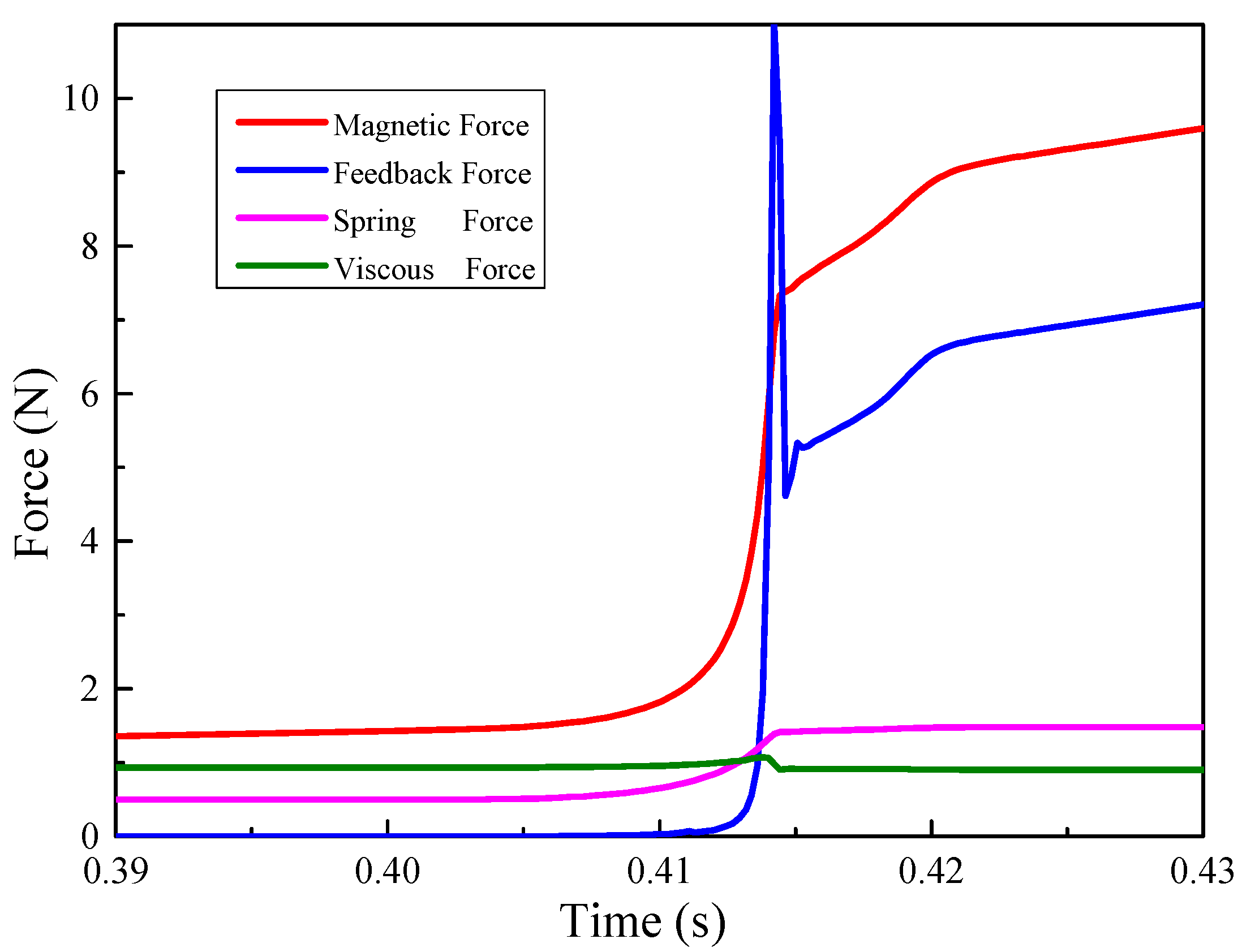
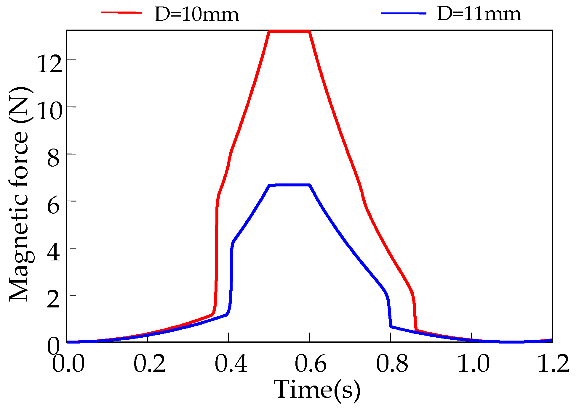
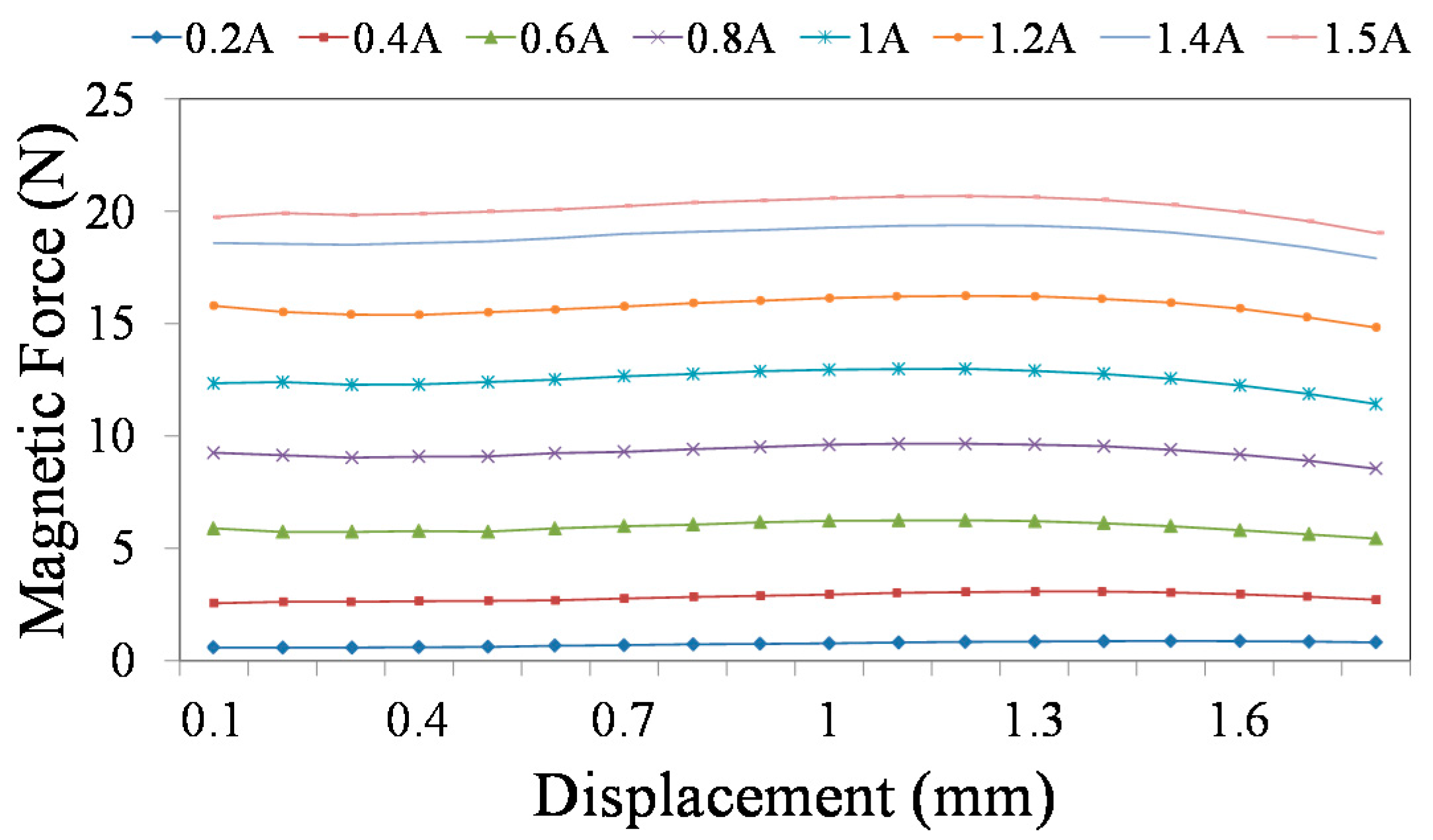
4.2. Analysis of Forces
4.3. Analysis of Leakage Flow
5. Conclusions
- (1)
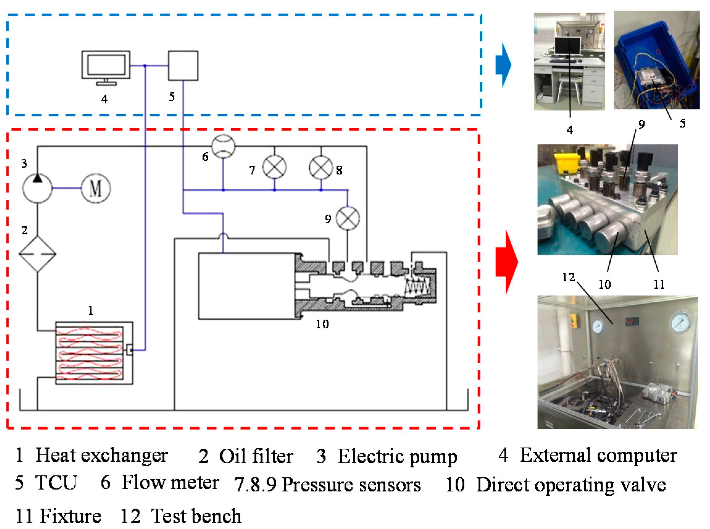
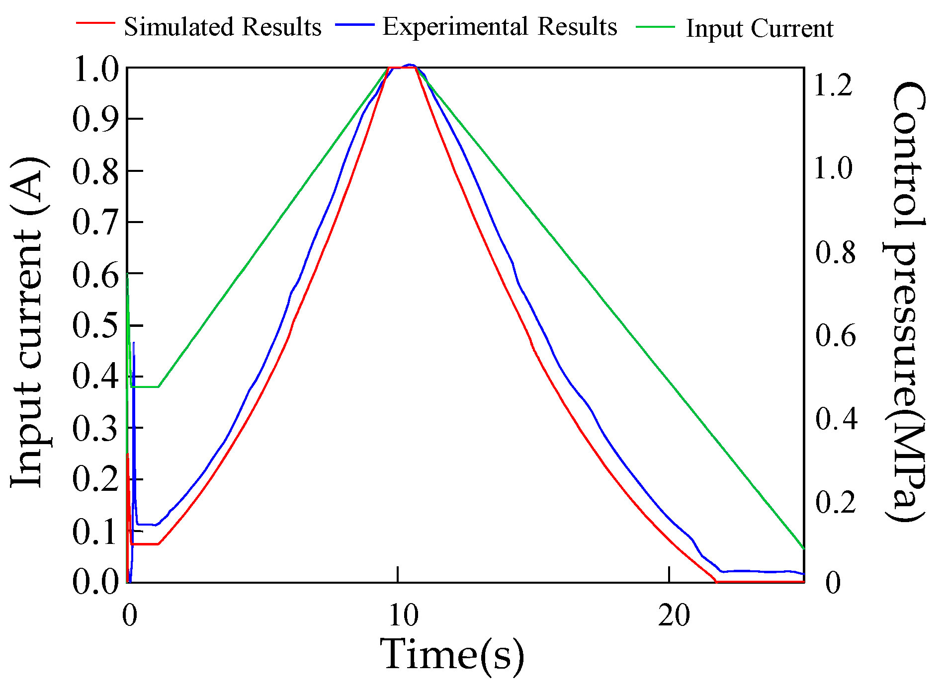
- The simulation results of this study agreed with the experimental results. Thus, the mathematical model developed in this study was effective and accurate.
- (2)
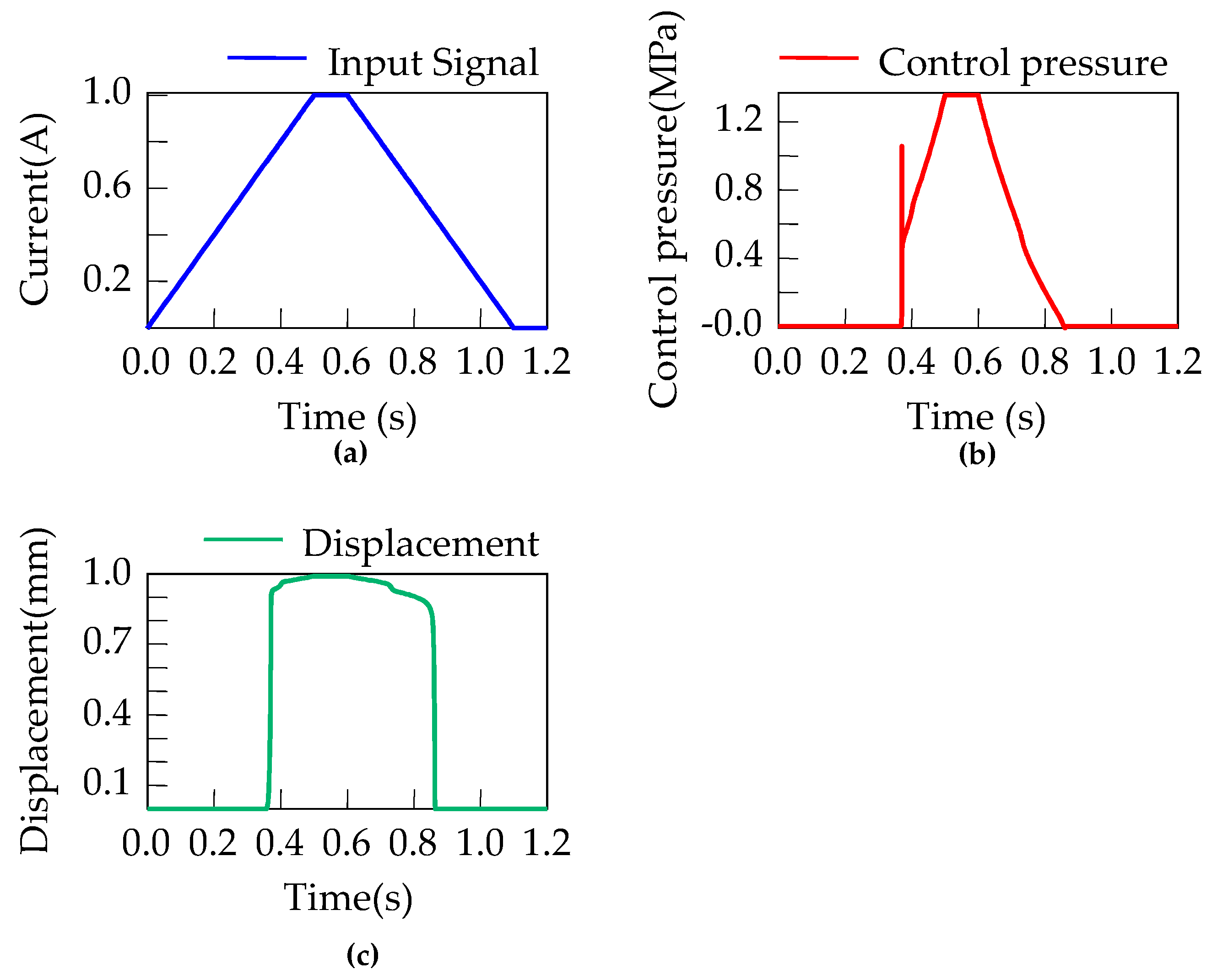
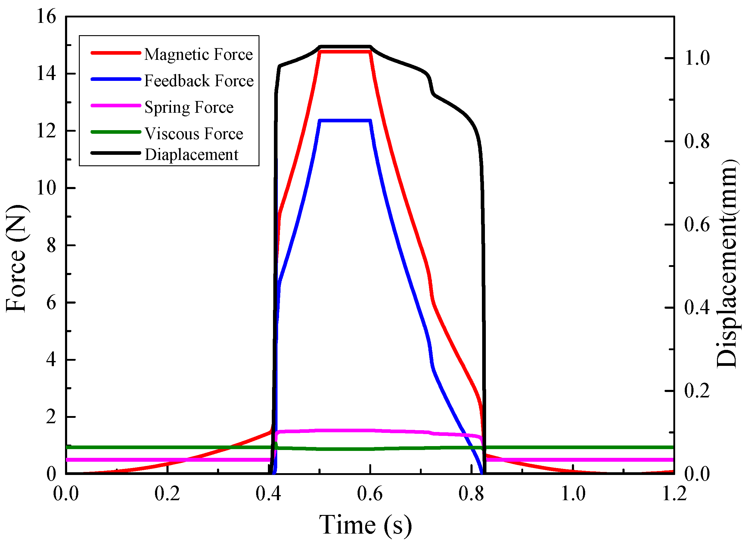
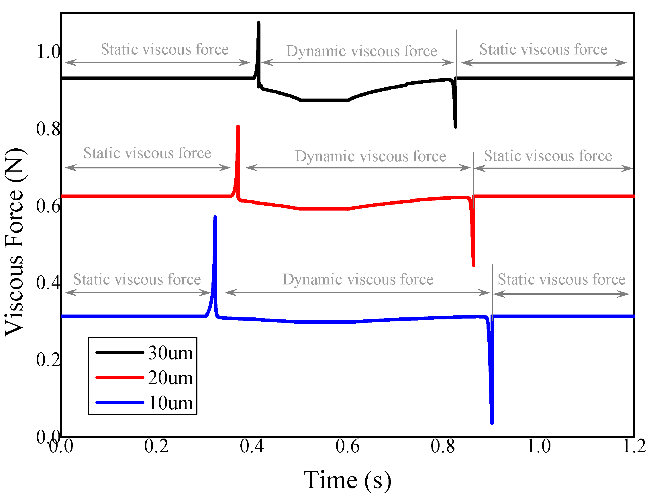
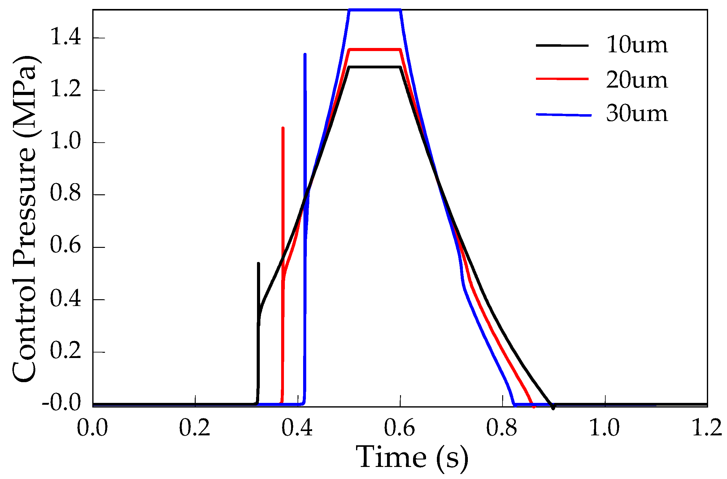
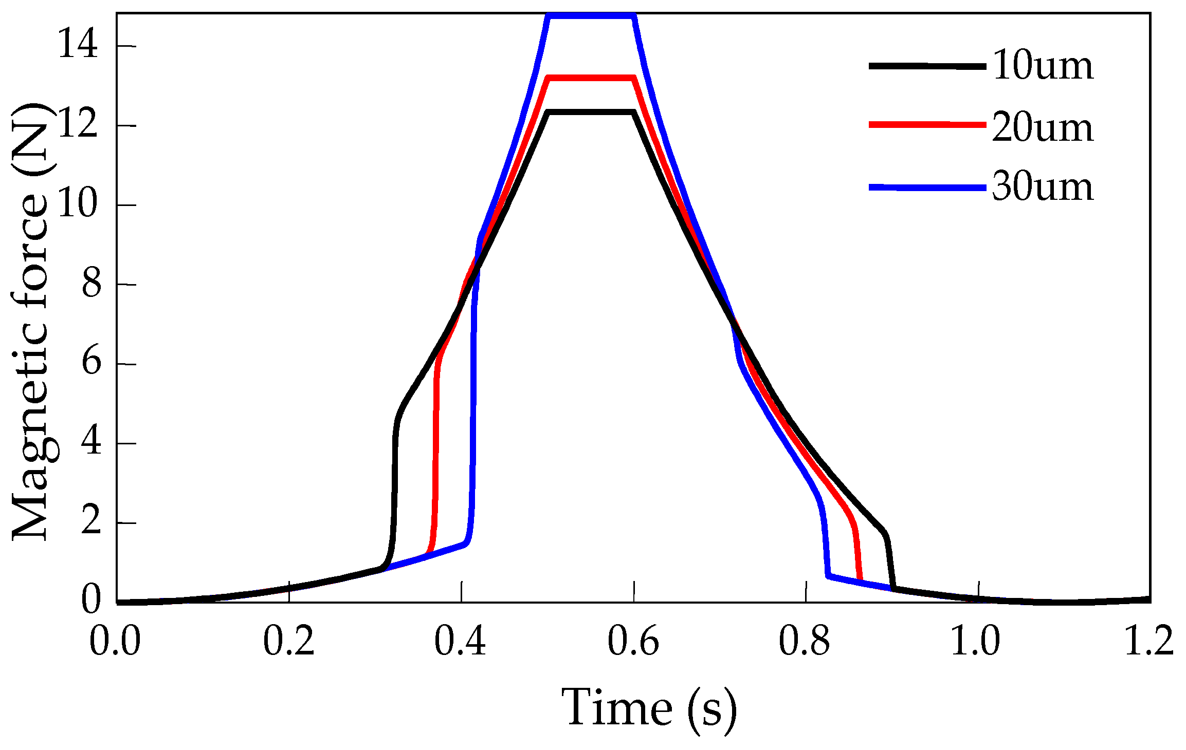
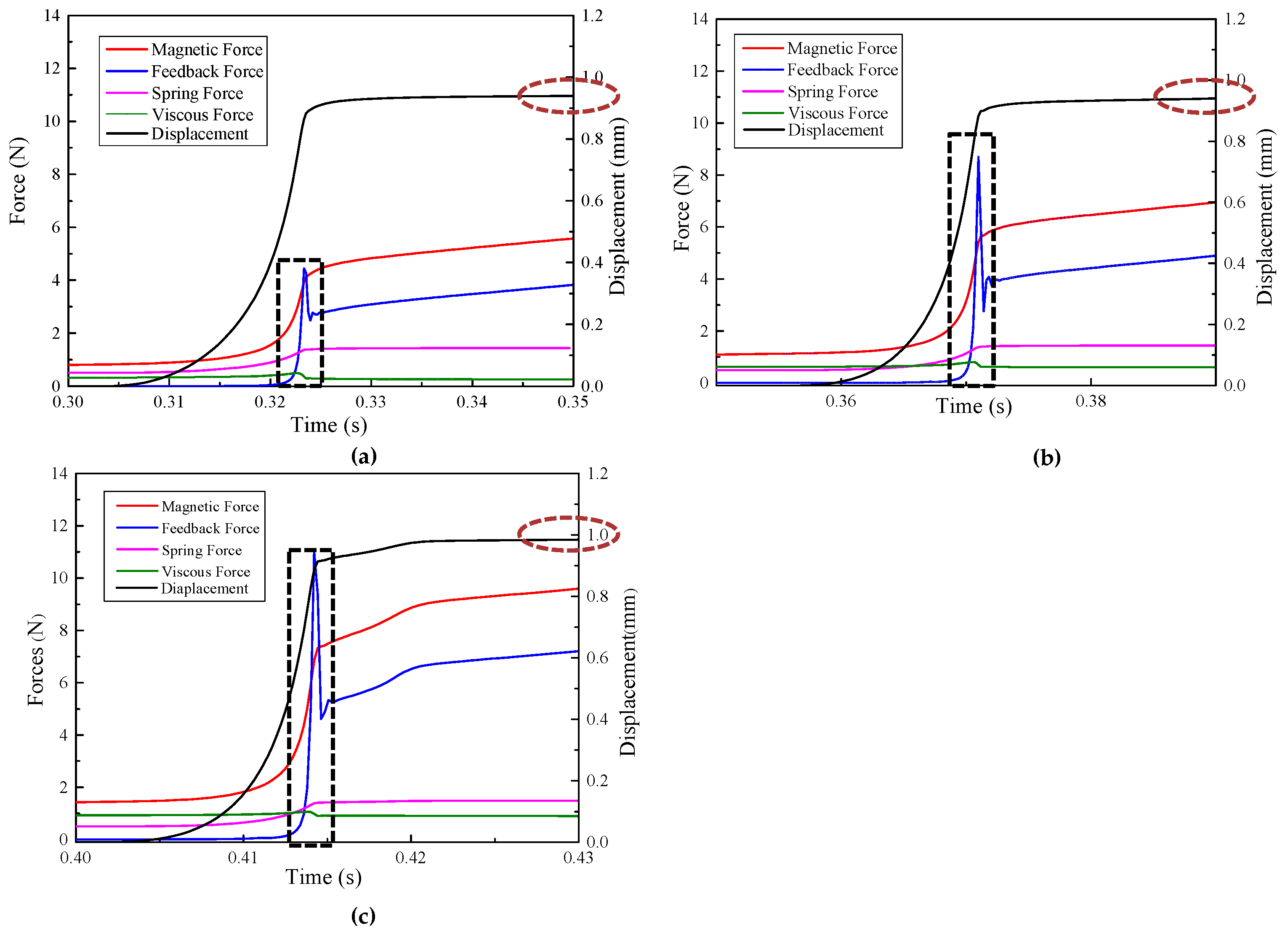
- Both the magnetic force and the viscous force had significantly influence on the pressure response. The pressure response time would be shortened if the magnetic force responded faster or the viscous force was reduced.
- (3)
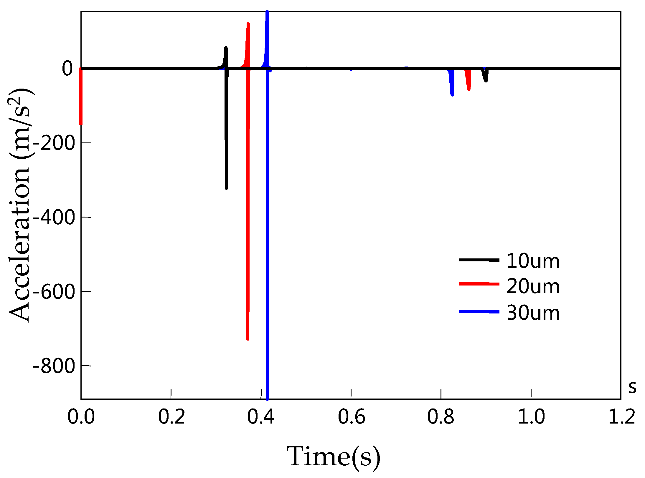
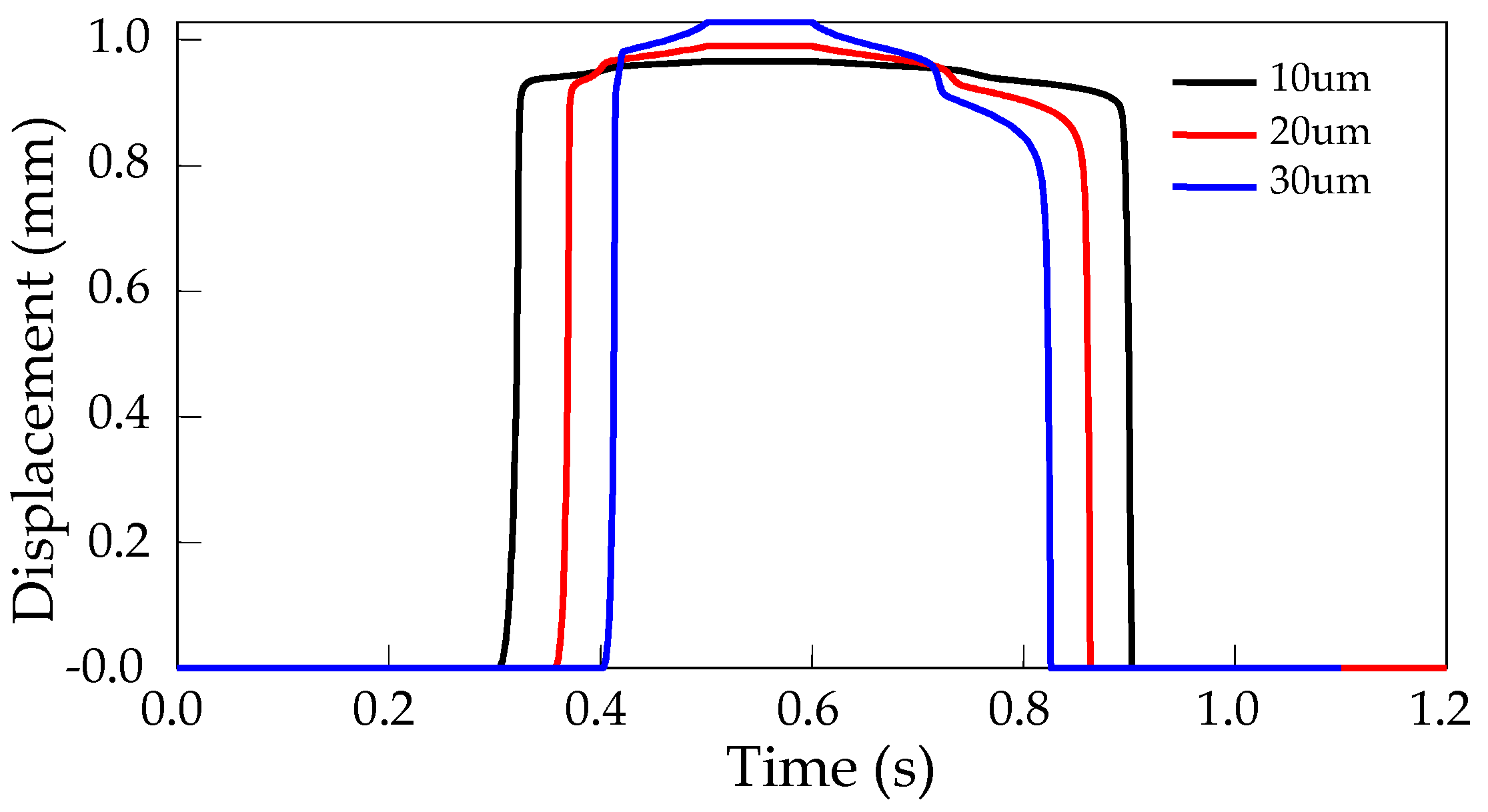
- To improve the response time of the solenoid valve, the clearance height should be reduced. The resultant force on the spool in 10 µm would reach the equilibrium point 0.1 s earlier than that in 30 µm.
- (4)
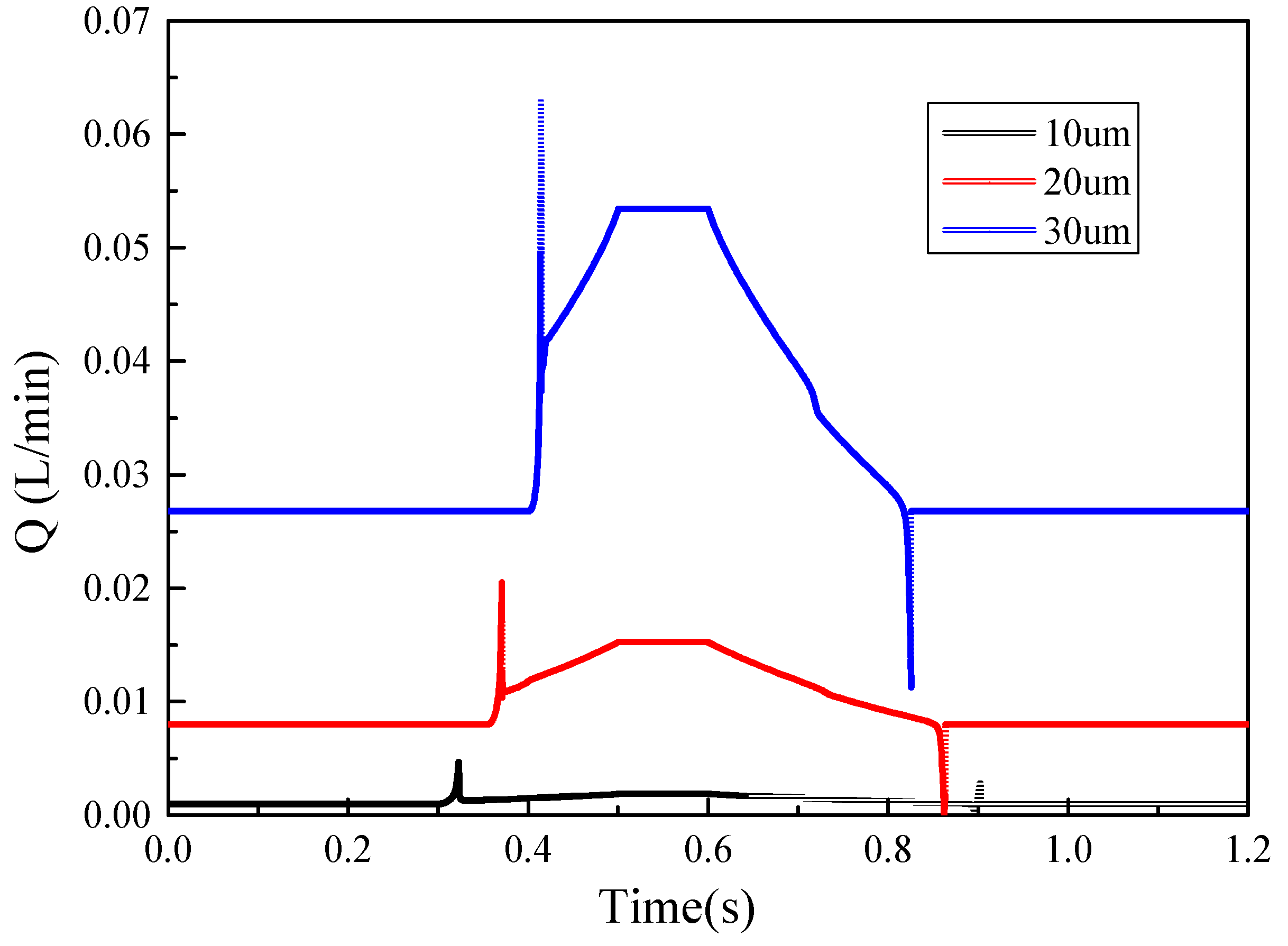
- The clearance height was proved to have great influence on the leakage of the solenoid valve. The leakage increases with the growing clearance height, which showed the leakage in 30 µm was triple the amount of that in 20 µm.
- (5)
- The leakage of the shifting control system employing the direct acting solenoid valve can be reduced by 60% compared to the conventional two-stage pilot valve in our previous product.
Acknowledgments
Author Contributions
Conflicts of Interest
References
- Wu, S.; Jiao, Z.; Yan, L.; Zhang, R.; Yu, J.; Chen, C.Y. Development of a direct-drive servo valve with high-frequency voice coil motor and advanced digital controller. IEEE/ASME Trans. Mechatron. 2014, 19, 932–942. [Google Scholar] [CrossRef]
- Schultz, A. Transient Simulation to Improve the Solenoid Dynamic in Pneumatic Valves. Ph.D. Thesis, Institute for Fluid Power Drives and Controls of RWTH, Aachen, Germany, 2004. [Google Scholar]
- Wang, Z. Optimum Research on the Great Flow and Fast Response Electromagnetic Valve Used in the Medium Pressure Common Rail System of Diesel Engine. Master’s Thesis, Wuhan University of Technology, Wuhan, China, 2006. [Google Scholar]
- Liu, Q.; Bo, H.; Qin, B. Design and analysis of Direct Action Solenoid Valve. At. Energy Sci. Technol. 2010, 44, 706–711. [Google Scholar]
- Shin, Y.; Lee, S.; Choi, C.; Kim, J. Shape optimization to minimize the response time of direct-acting solenoid valve. J. Magn. 2015, 20, 193–200. [Google Scholar] [CrossRef]
- Lee, G.S.; Sung, H.J.; Kim, H.C.; Lee, H.W. Flow force analysis of a variable force solenoid valve for automatic transmissions. J. Fluids Eng. 2010, 132, 031103. [Google Scholar] [CrossRef]
- Mutschler, K.; Dwivedi, S.; Kartmann, S.; Bammesberger, S.; Koltay, P.; Zengerle, R.; Tanguy, L. Multi physics network simulation of a solenoid dispensing valve. Mechatronics 2014, 24, 209–221. [Google Scholar] [CrossRef]
- Liu, Y.; Dai, Z.; Xu, X.; Tian, L. Multi-domainmodelingandsimulationofproportionalsolenoidvalve. J. Cent. South Univ. 2011, 18, 1589–1594. [Google Scholar] [CrossRef]
- Liu, Z.; Han, X.; Liu, Y. Dynamic Simulation of Large Flow Solenoid Valve. In Proceedings of the ASME 2016 International Mechanical Engineering Congress and Exposition, Phoenix, AZ, USA, 11–17 November 2016; ASME: New York, NY, USA, 2016; p. V009T012A015. [Google Scholar]
- Xiong, Y.; Wei, J.; Feng, R. Adaptive robust control of a high-response dual proportional solenoid valve with flow force compensation. Proc. Inst. Mech. Eng. Part I J. Syst. Control Eng. 2015, 299, 3–26. [Google Scholar] [CrossRef]
- Zhu, Y.; Jin, B. Analysis and modeling of a proportional directional valve with nonlinear solenoid. J. Braz. Soc. Mech. Sci. Eng. 2015, 2, 1–8. [Google Scholar] [CrossRef]
- Liu, L.; Zhang, D.; Zhao, J. Design and research for the water medium low pressure large-flow pilot operated solenoid valve. Strojniski Vestnik 2014, 60, 10. [Google Scholar]
- Park, C.D.; Lim, B.J.; Chung, K.Y. Design verification methodology for a solenoid valve for industrial applications. J. Mech. Sci. Technol. 2015, 29, 677–686. [Google Scholar] [CrossRef]
- Wang, L.; Li, G.X.; Xu, C.L.; Xi, X.; Wu, X.J.; Sun, S.P. Effect of characteristic parameters on the magnetic properties of solenoid valve for high-pressure common rail diesel engine. Energy Convers. Manag. 2016, 127, 656–666. [Google Scholar] [CrossRef]
- Zhao, J.; Fan, L.; Liu, P.; Grekhov, L.; Ma, X.; Song, E. Investigation on electromagnetic models of high-speed solenoid valve for common rail injector. Math. Probl. Eng. 2017, 2017, 1–10. [Google Scholar] [CrossRef]
- Walker, P.D.; Zhu, B.; Zhang, N. Nonlinear modeling and analysis of direct acting solenoid valves for clutch control. J. Dyn. Syst. Meas. Control 2014, 136, 562–576. [Google Scholar] [CrossRef]
- Shi, Y.; Wu, T.; Cai, M.; Wang, Y.; Xu, W. Energy conversion characteristics of a hydropneumatic transformer in a sustainable-energy vehicle. Appl. Energy 2016, 171, 77–85. [Google Scholar] [CrossRef]
- Shi, Y.; Wang, Y.; Liang, H.; Cai, M. Power characteristics of a new kind of air-powered vehicle. Int. J. Energy Res. 2016, 40, 1112–1121. [Google Scholar] [CrossRef]
- Shi, Y.; Wu, T.; Cai, M.; Liu, C. Modelling and study on the output flow characteristics of expansion energy used hydropneumatic transformer. J. Mech. Sci. Technol. 2016, 30, 1163–1170. [Google Scholar] [CrossRef]
- Cai, M.; Wang, Y.; Shi, Y.; Liang, H. Output dynamic control of a late model sustainable energy automobile system with nonlinearity. Adv. Mech. Eng. 2016, 8, 1–11. [Google Scholar] [CrossRef]
- Xu, Q.; Cai, M.; Shi, Y. Dynamic heat transfer model for temperature drop analysis and heat exchange system design of the air-powered engine system. Energy 2014, 68, 877–885. [Google Scholar] [CrossRef]
- Xu, Q.; Shi, Y.; Yu, Q.; Cai, M. Virtual prototype modeling and performance analysis of the air-powered engine. ARCHIVE Proc. Inst. Mech. Eng. Part C J. Mech. Eng. Sci. 2014, 228, 2642–2651. [Google Scholar]
- Yu, Q.; Cai, M.; Shi, Y. Working characteristics of two types of compressed air engine. J. Renew. Sustain. Energy 2016, 8, 397–411. [Google Scholar] [CrossRef]
- Shi, Y.; Cai, M. Dimensionless study on output flow characteristics of expansion energy used pneumatic pressure booster. J. Dyn. Syst. Meas. Control 2013, 135, 021007. [Google Scholar] [CrossRef]
- Yu, Q.; Cai, M.; Shi, Y.; Yuan, C. Dimensionless study on efficiency and speed characteristics of a compressed air engine. J. Energy Resour. Technol. 2015, 137, 044501–044509. [Google Scholar] [CrossRef]

© 2017 by the authors. Licensee MDPI, Basel, Switzerland. This article is an open access article distributed under the terms and conditions of the Creative Commons Attribution (CC BY) license (http://creativecommons.org/licenses/by/4.0/).
Share and Cite
Xu, X.; Han, X.; Liu, Y.; Liu, Y.; Liu, Y. Modeling and Dynamic Analysis on the Direct Operating Solenoid Valve for Improving the Performance of the Shifting Control System. Appl. Sci. 2017, 7, 1266. https://doi.org/10.3390/app7121266
Xu X, Han X, Liu Y, Liu Y, Liu Y. Modeling and Dynamic Analysis on the Direct Operating Solenoid Valve for Improving the Performance of the Shifting Control System. Applied Sciences. 2017; 7(12):1266. https://doi.org/10.3390/app7121266
Chicago/Turabian StyleXu, Xiangyang, Xiao Han, Yanfang Liu, Yanjing Liu, and Yang Liu. 2017. "Modeling and Dynamic Analysis on the Direct Operating Solenoid Valve for Improving the Performance of the Shifting Control System" Applied Sciences 7, no. 12: 1266. https://doi.org/10.3390/app7121266
APA StyleXu, X., Han, X., Liu, Y., Liu, Y., & Liu, Y. (2017). Modeling and Dynamic Analysis on the Direct Operating Solenoid Valve for Improving the Performance of the Shifting Control System. Applied Sciences, 7(12), 1266. https://doi.org/10.3390/app7121266


