Perspective

A New Line for Laser-Driven Light Ions Acceleration and Related TNSA Studies

by
Leonida Antonio Gizzi
1,2,*,
Dario Giove
3,
Carmen Altana
4,5,
Fernando Brandi
1,6,
Pablo Cirrone
5,
Gabriele Cristoforetti
1,
Alberto Fazzi
7,
Paolo Ferrara
1,
Lorenzo Fulgentini
1,
Petra Koester
1,
Luca Labate
1,2,
Gaetano Lanzalone
5,8,
Pasquale Londrillo
9,
David Mascali
5,
Annamaria Muoio
5,
Daniele Palla
1,2,10,
Francesco Schillaci
5,11,
Stefano Sinigardi
9,
Salvatore Tudisco
5 and
Giorgio Turchetti
9
1
Intense Laser Irradiation Laboratory (ILIL), Istituto Nazionale di Ottica (INO), Consiglio Nazionale delle Ricerche (CNR), Via G. Moruzzi 1, 56124 Pisa, Italy
2
Istituto Nazionale di Fisica Nucleare (INFN) Sezione di Pisa, Largo Pontecorvo 3, 56127 Pisa, Italy
3
Istituto Nazionale di Fisica Nucleare, Laboratorio Acceleratori e Superconduttività Applicata (INFN-LASA), Via Fratelli Cervi 201, 20090 Segrate, Italy
4
Dipartimento di Fisica e Astronomia, Università degli Studi di Catania, 95123 Catania, Italy
5
Laboratori Nazionali del Sud, INFN, Via S. Sofia, 95125 Catania, Italy
6
Istituto Italiano di Tecnologia, Via Morego 30, 16163 Genova, Italy
7
Dipartimento di Energia, Politecnico di Milano and INFN, Sezione di Milano, via Lambruschini 4, 20156 Milano, Italy
8
Università degli Studi di Enna Kore, Via delle Olimpiadi, 94100 Enna, Italy
9
Dipartimento di Fisica e Astronomia, Università di Bologna and INFN, Sez. di Bologna, 40126 Bologna, Italy
10
Dipartimento di Fisica, Università di Pisa, 56124 Pisa, Italy
11
Institute of Physics Czech Academy of Science, ELI-Beamlines, Za Radnicí 835, 252 41 Dolní Břežany, Czech Republic
*
Author to whom correspondence should be addressed.
Appl. Sci. 2017, 7(10), 984; https://doi.org/10.3390/app7100984
Submission received: 4 August 2017 / Revised: 29 August 2017 / Accepted: 6 September 2017 / Published: 25 September 2017
(This article belongs to the Special Issue Laser-Driven Particle Acceleration)

Abstract

:
In this paper, we present the status of the line for laser-driven light ions acceleration (L3IA) currently under implementation at the Intense Laser Irradiation Laboratory (ILIL), and we provide an overview of the pilot experimental activity on laser-driven ion acceleration carried out in support of the design of the line. A description of the main components is given, including the laser, the beam transport line, the interaction chamber, and the diagnostics. A review of the main results obtained so far during the pilot experimental activity is also reported, including details of the laser-plasma interaction and ion beam characterization. A brief description of the preliminary results of a dedicated numerical modeling is also provided.

1. Introduction

The development of novel ion acceleration techniques based on ultra-intense lasers has been developing rapidly in the past decades due to the dramatic progress of laser systems capable of delivering increasingly higher power laser pulses. Based on these developments, laser-driven acceleration is now moving from pure scientific exploration to applications. As described in details in several recent review papers, the primary process known as Target Normal Sheath Acceleration (TNSA) [1] is a robust mechanism to accelerate light ions from laser interaction with thin foil targets with exceptional properties including high brightness and high spectral cut-off, high directionality and laminarity, as well as short pulse duration. The process has been explored for a wide range of laser and target parameters in addition to target specifications [2], and has proven to be reliable and relatively easy to implement to accelerate light ions such as protons, deuterons, boron, carbon, oxygen, to energies up to several tens of MeV using large laser systems producing sub-ps pulses with tens or hundreds of Joules per pulse. The main challenges of the current research on TNSA include the control of acceleration parameters, namely cut-off energy, beam divergence, charge, and emittance. At the same time, experimental investigation is also being dedicated to target optimization and engineering, looking at different properties of surface, geometry, and conductivity. Finally, post-acceleration control is being tackled with special attention to selection, collimation [3], and, eventually, injection in secondary acceleration structures, even using miniature target-driven guiding devices [4].
Indeed, ions beams produced with TNSA are ideal for applications where high ion flux is required with relatively large energy spread. Examples of applications include injectors for high power ion beams, neutron generation [5] for high power ion beams, and probes for fast evolving phenomena like the ultrafast charging of laser-heated samples [6]. Additionally, laser-driven ion beams have been proposed for space radiation studies and electronic components testing [7]. A more specific application with potential impact on industry and cultural heritage is the proton-induced X-ray emission spectroscopy (PIXE), which may be applicable with currently achievable TNSA performances and may strongly benefit from the compactness of a multi-MeV laser-driven ion source [8]. For these applications to emerge, the operation of laser-driven ion acceleration should be practical and reliable. In this context, the operation of a compact, high-intensity proton beam line at 10 MeV has been demonstrated recently [9]. However, for practical applications, compact, Joule-scale laser systems in the sub-100 fs domain [10] are much more attractive [11] for their higher repetition rate, potentially reaching the 100 Hz or even the kHz range with diode-pumping [12], which may allow future laser-driven accelerators to reach a repetition rate in the kHz range. Here, we describe a new initiative aimed at the construction of an all-optical accelerator line for light ions using a multi-J class, femtosecond laser system. The line for laser-driven light ions acceleration (L3IA) project has the purpose of establishing an outstanding beam-line operation of a laser-plasma source in Italy, taking advantage of the results achieved so far in this field by the precursor experimental campaigns [13] and numerical modeling. The beam-line will operate at a newly developed sub-petawatt (PW) scale laser installation to enter the parameter range of ion acceleration currently being explored by leading European laboratories in this field, and will provide an advanced test facility for the development and exploitation of laser-driven ion sources. The beam-line development is linked to a strong research and development programme with clear goals, deliverables, and objectives, implementing the required laser-plasma technology and beam diagnostics and control techniques.

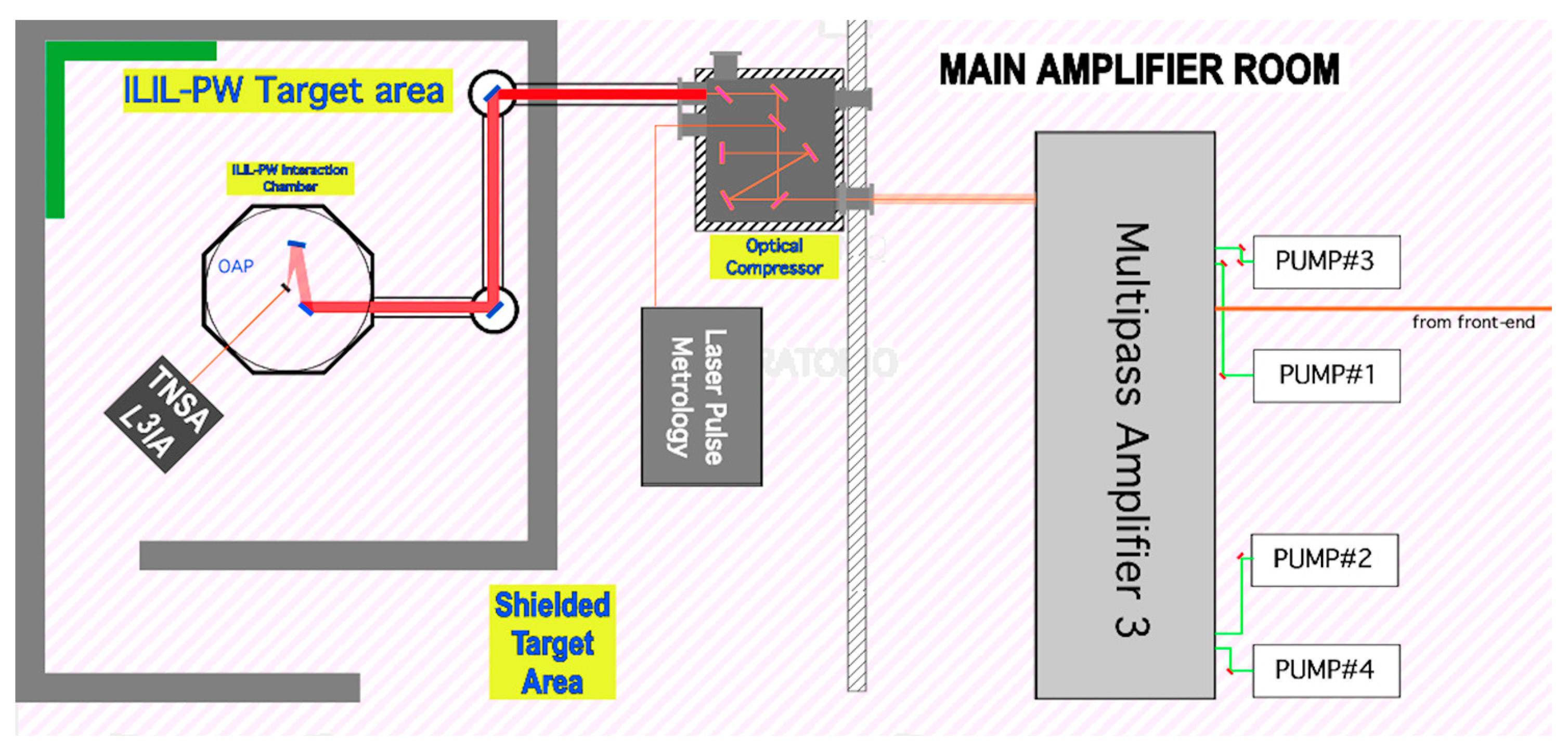
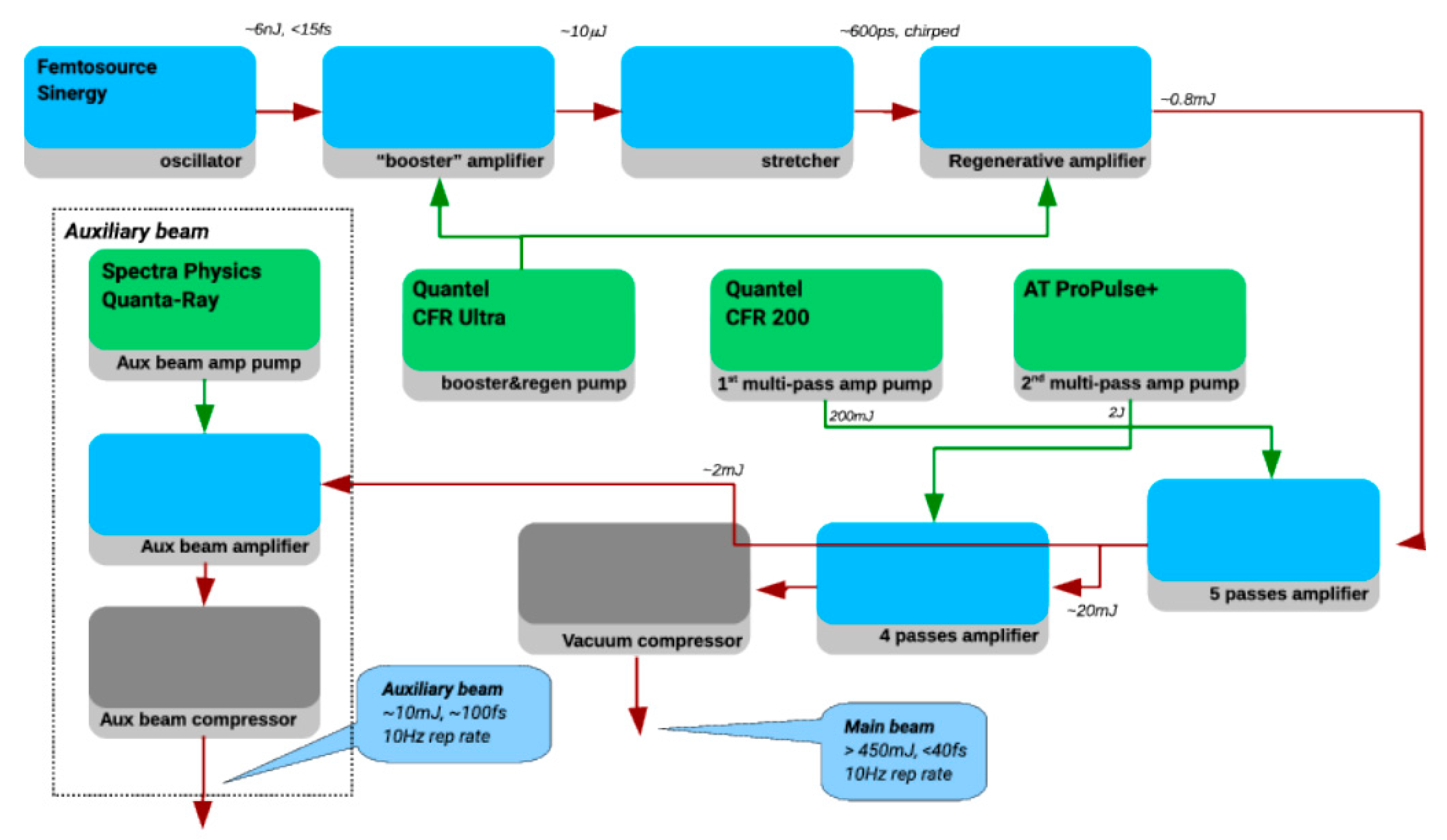
2. Materials and Methods: The ILIL-PW Laser Facility

The L3IA will be established at the Intense Laser Irradiation Laboratory and will be based at INO-CNR where the ILIL-PW laser installation features a >200 TW laser system, a beam transport line, and a multi-purpose interaction area with radiation shielding. An overview of the ILIL-PW facility is shown in Figure 1, while a summary of the main laser parameters is given in the table of Table 1. The 10-Hz front-end is shown schematically in Figure 2, with the oscillator producing 15 fs pulses at approximately 6 nJ. A “booster” unit amplifies the oscillator pulse to the 10 μJ level and is followed by a stretcher that delivers a chirped pulse with a duration of 600 ps to the regenerative amplifier. The mJ energy pulse is further amplified by a 5-pass amplifier followed by a 4-pass amplifier, finally delivering 600 mJ at 800 nm. The output pulses of the front-end are then transported to the final 4-pass amplifier, pumped by four Nd:YAG lasers (Titan6 by Amplitude Technologies) delivering a total of 24 J pulses at 532 nm at a maximum rep-rate of 5 Hz. The 800-nm pulse is thus amplified up to >7 J and compressed down to <25 fs. Pulse duration control is achieved through standard techniques based on acousto-optical devices placed in the front-end to achieve control of spectral gain, phase, and amplitude. The pulse energy losses due to acousto-optics devices are compensated in the amplification stages. Pump fluence throughout the front-end system is kept below 1 J/cm2 to operate well below the Ti:Sa crystal damage threshold [14], yielding a typical energy extraction efficiency of less than 30%.
The compressed pulse is then transported under vacuum to the octagonal interaction chamber via two remotely controlled, beam steering chambers. The beam is then focused on a target by an F/3 Off-Axis Parabolic (OAP) mirror to an intensity in excess of 1020 W/cm2. The interaction chamber is equipped with a remotely controlled motorized target mount with a sub-micrometer resolution capable of XYZ translation and azimuthal rotation around the vertical axis.
The target mount was designed to enable a 100-mm range of positioning and withstand a load of up to 500 N in all directions of motion. These specifications ensure that the scanning of targets up to 100 mm × 100 mm can be accomplished, enabling a large number of laser shots to be fired on a given target (typically up to 103) before target replacement is required.
The output from the front-end can be compressed independently to deliver 450 mJ in a 30 fs pulse with an M2 < 1.5 to a separate interaction chamber, which is used for the pilot experimental activity. Cross-correlation measurement of the laser pulse show [15] that the front-end laser contrast remains above 1010 up to 10 ps before the peak of the pulse, and decreases to 106, 1 ps before the peak of the pulse.

3. L3IA Development Plan

The L3IA project aiming at the development of the ion acceleration line includes a complete set of work-packages, including the interface with the ILIL-PW hosting facility, and the beam line scheme comprising targets, laser beam focusing, and diagnostic devices dedicated to both the laser-plasma interaction and the ion beam detection and characterization. Numerical modeling is also included, with the specific tasks of providing basic predictive simulations for the baseline parameters of the beam line as well as allowing for the investigation of advanced target and laser configurations. Provision is also made for specific application cases, including radiobiological testing and cultural heritage applications.
In fact, the project develops in two stages that build on the laser upgrade phases described in Table 1. The first phase will establish TNSA operation at a cut-off energy >6 MeV, using standard thin foil targets optimized for the laser performances, with particular attention paid to the available laser contrast. The second phase will be mainly dedicated to the control and enhancement of the laser contrast, to enable the use of targets with nano-structured targets [16] to enhance laser absorption as recently investigated by our collaboration. Moreover, the higher contrast will allow sub-micron thickness targets to be used to increase the cut-off energy, as originally demonstrated by T. Ceccotti and co-workers [17]. In fact, our pilot experimental activity summarized below shows that the existing laser contrast gives rise to plasma formation with a micrometer spatial scale, which limits the use of this kind of target. Based on this enhancement of the laser performance, and on the additional increase of laser pulse energy described in Table 1, the second phase of the project is expected to establish TNSA operation at a cut-off energy >12 MeV. Along with these source developments, the project also includes post-acceleration manipulation of the accelerated ions, with collection, collimation, and energy selection and transport. Based on the output from the beam characterization phase, we will tune post-acceleration devices to obtain the highest collection and the highest throughput of protons to the sample for pilot applications including radiobiology and PIXE studies. Our foreseen applications have been selected on the basis of compatibility with the inherent properties of the TNSA-accelerated beam of protons, namely large energy spread and large peak current. Our setup will include a vacuum-air interface to access the beam in air and provide sample exposure at standard pressure and temperature. A quantitative design of this transport line is currently in progress and will be the subject of future publications.

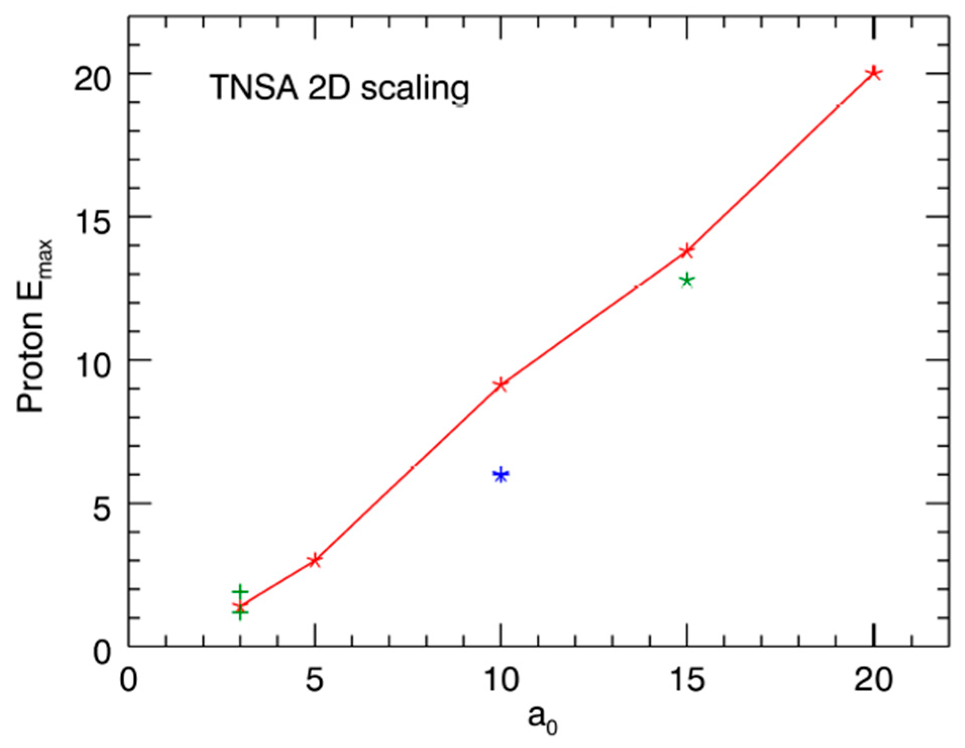
4. Results: Numerical Investigation of TNSA Regime

Numerical simulations were carried out using the ALaDyn code [18] following the prospects outlined in the table of Table 1. We considered a laser pulse with a duration of τ = 25–40 fs full width half maximum (FWHM) and a Gaussian focal spot Df = 7.5 μm, with an energy per pulse in the range of EL = 0.4–6 J. The corresponding peak intensity ranges from 2 × 10¹⁹ to 5 × 10²⁰ and the normalized intensity a0 = 0.85(2/1018 W/cm2)1/2 ranges from 3 to 15. Some simulations with higher intensity were also considered. The lower intensity value corresponds to the front-end laser operation, which has been extensively explored [15,19,20] and was found to be fully consistent with the above scaling. In the simulations, the laser impinges with different angles θ = 0°, 10°, 15°, 30° on a fully ionized, CH2 slab with a thickness lth = 2–2.5 μm and electronic density ne = 100nc = 1.74 × 1023 cm−3. No effects originating from pre-plasma due to finite pre-pulse are taken into account. The first outcome of Particle In Cell (PIC) investigation summarized in Figure 3 shows a significant dependence of proton acceleration on the laser incidence angle, but only at lower intensities a0 < 5. In this range, going from incidence θ = 0° to θ = 30°, the proton cut-off energy increases by 40%. At higher intensities, a0 > 10, this factor drops to only a few percentage points.
In PIC simulations, systematic parametric scans are necessarily restricted to 2D geometry. The main difficulty to extract useful quantitative information on proton acceleration is that 2D TNSA models give a logarithmic increase with time of the Em(t) energy. The choice of a definite time at which to stop the simulation to evaluate the final proton energy is therefore intrinsically arbitrary. To overcome this limitation, a method has been introduced [21] that allows a unique proton energy, the so-called asymptotic E value, to be extracted using only the information on the growth rate of energy in a finite time range. The results reported in Figure 3 were consistent with this approach, which enabled a more detailed description of the intensity and angular dependence of TNSA cut-off energy.

5. Results: Pilot Experimental Activity

The pilot experimental activity presented here was carried out using the laser pulse at the output of the front-end. The pulse was compressed in a separate compressor chamber and focused, at an angle of incidence of 15° or 30°, using an f/4.5 off-axis parabolic mirror (OAP), in a spot size of 6.2 μm (FWHM), giving a nominal intensity on the target of about 2 × 10¹⁹ (a0 = 3). A schematic view of the pilot experimental setup is given in Figure 4. Special attention was dedicated in the experimental campaign to the target integrity prior to the arrival of the main pulse on the target, which strongly depends on the temporal profile of the laser pulse [22].
To this purpose, we used optical spectroscopy of the light scattered in the specular direction to monitor the generation of second harmonic emission, 2ωL, and (3/2)ωL of the incident laser light. These components of the scattered radiation are associated with the coupling of the laser light at the critical density and at the quarter critical density, respectively [23]. In fact, the formation of even a very small pre-plasma before of the arrival of the main pulse can provide suitable conditions for the growth of stimulated instabilities including the Stimulated Raman Scattering and the Two Plasmon Decay. Electron plasma waves at ωL/2 generated by the instabilities can couple non-linearly with incident laser light and give rise to (3/2)ωL emission. This emission is therefore a signature of the presence of even a small pre-plasma. Second harmonic emission in the specular direction is instead generated by the non-linear interaction of the main laser pulse at the critical density [24]. Therefore, second harmonic emission can be taken as a signature of the presence of a critical density layer in the plasma at the time of interaction of the main pulse, a prerequisite for the interaction with an over-dense target and the occurrence of TNSA. In our experiments, in spite of the increase of the (3/2)ωL intensity, the intensity of the 2ωL emission remained significant, indicating that the laser contrast in the best focus was sufficient to ensure the survival of the target rear surface and, therefore, the proper onset of the TNSA accelerating field.
Another crucial issue in this class of experiments is the control of the irradiation intensity on the target, which is complicated by the typically very short depth of focus of the focusing optics. These circumstances make the irradiation intensity very sensitive to small changes in the position of the target relative to the best focus. Also, small changes in the thermal lensing in the laser amplifiers may lead to changes in the position of the best focus which, if not compensated for, can change irradiation conditions. To this purpose, as shown in Figure 4, optical imaging of the rear side of the target at 45° from the target normal was performed to detect Optical Transition Radiation (OTR) generated from electrons crossing the target rear surface as a marker of optimum focusing conditions. OTR intensity is also very sensitive to the sharpness of the density transition across the rear surface [25], and is therefore a useful additional indicator of the integrity of the target rear surface.
We also measured fast electron emission from the target rear side in the forward direction. Forward escaping fast electrons were detected and analyzed using a permanent magnet electron spectrometer with a detection range from 1 MeV to 5 MeV. Measurements were carried out with the target placed either at the best focus position or 100 μm, corresponding to two Rayleigh lengths, away from the best focus towards the off-axis parabola. As shown in Figure 5, clear forward electron emission was detected in the condition of best focus while no electron emission was detectable out of focus. These circumstances were confirmed by the rear side images, which clearly show optical emission (OTR) strongly correlated with the forward escaping fast electrons. In addition, OTR images (not shown here) taken for different target materials and thicknesses exhibited similar spectral and angular properties. These measurements enabled us to confirm that a simple optical imaging of the target rear side gives accurate shot-by-shot information of the optimum laser focusing on the target and of the quality of the target rear surface.

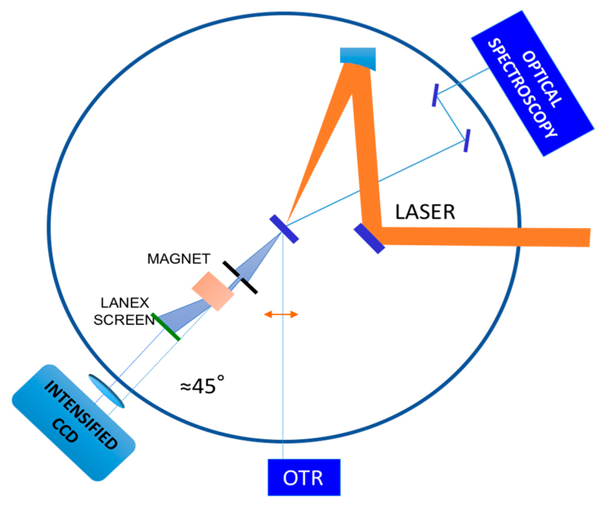
6. Results: Ion Detection

Concerning ion detection, a range of diagnostics was used in our experiments to measure ion acceleration, including radio-chromic films (GAF), CR39, Thomson Parabola, and Time of Flight (TOF) diamond detectors. Normally, Thomson Parabola, and TOF detectors were used simultaneously so that a cross-comparison of the signals obtained from the two devices was possible. This was done in view of a possible use of the diamond detector for on-line direct detection of accelerated ions during normal beamline operation. A detailed discussion of all these measurements with different detectors is given elsewhere [15,19]. Here, we focus our attention on the interpretation of the TOF signal in particular. The plot of Figure 6a shows the TOF signal obtained with the diamond detector from the irradiation of a 5 μm thick Mylar target and with a laser angle of incidence on the target of 30°. The detector was placed at a distance of 30 cm and was filtered using a 12 μm thick Al foil. The strong peak at −10 ns was originally attributed to a combination of X-rays and fast electrons reaching the detector soon after the interaction.
This peak is followed by the actual ion signal that, as shown by the blue arrow, starts at 4 ns, namely, 15 ns after the starting of the photo-peak. Taking into account the TOF distance and assuming a signal predominantly due to protons that have the highest charge-to-mass ratio, calculations yield a high energy cut-off of approximately 2 MeV. A similar measurement carried out placing a magnetic dipole with a 1T magnetic field in front of the diamond detector is shown in Figure 6b. This measurement shows that the peak at −10 ns is strongly reduced, leaving a clean proton signal, indicating that the peak was due to the presence of fast electrons that are stopped by the strong magnetic field. Incidentally, the measurements of Figure 6 were obtained at the 30° angle of incidence, which is comparable to the maximum energy of 1.9 MeV obtained [15] on the 10 μm Al target at a 15° angle of incidence, indicating that such a change in the angle of incidence does not lead to significant changes of the interaction conditions. This is consistent with the numerical simulation results of Figure 3 where, for similar values of laser intensity, no significant dependence on the angle of incidence was expected. A more systematic investigation is planned to confirm the observed behavior with the angle of incidence and target thickness.

7. Conclusions

In summary, we described the L3IA project dedicated to the establishment of a new laser-driven light ions acceleration line based on the physical mechanism known as Target Normal Sheath Acceleration. The project takes advantage of the ongoing ILIL-PW upgrades at the Intense Laser Irradiation Laboratory, providing a sub-PW class laser combined with a new interaction area. The L3IA initiative was developed after major research and development advances in laser-driven ion acceleration in the TNSA regime, carried out during the past few years and dedicated to the establishment of the key scientific and technological aspects required for a reliable operation of the acceleration line. In particular, significant effort has been dedicated to the control of the underlying physical processes that play a role in the complex dynamics of TNSA: non-linear optical scattering occurring at the plasma interface as a quantitative marker of plasma formation; optical transition radiation imaging and fast electron energy measurements as a critical indicator of laser focusing quality; and finally, direct measurement of the ions cut-off energy. Pilot exploration of basic target parameters such as target material and thickness shows results well in line with expected values from dedicated numerical simulations and published results in this regime. All these aspects provide a quite complete characterization of the laser-target interaction regime in our experimental conditions and a reference set of ion acceleration data for the upcoming upgrade of the laser installation that is expected to soon provide a >20-fold increase in the laser power.

Acknowledgments

We acknowledge financial contribution from the CNR ELI-Italy Network funded by the MIUR for the upgrade of the ILIL-PW installation. The L3IA is a project of the INFN CSN5. This work is also partially supported by the MIUR-PRIN 2012 (Contract No. PRIN2012AY5LEL).

Author Contributions

Leonida Antonio Gizzi, Dario Giove, Fernando Brandi, Pablo Cirrone, Gabriele Cristoforetti, Alberto Fazzi, Petra Koester, Luca Labate and Salvatore Tudisco conceived, designed and realized the experimental setup. Leonida Antonio Gizzi, Dario Giove, Carmen Altana, David Mascali, Fernando Brandi, Francesco Schillaci, Gabriele Cristoforetti, Pasquale Londrillo, Alberto Fazzi, Stefano Sinigardi, Giorgio Turchetti, Paolo Ferrara, Lorenzo Fulgentini, Petra Koester, Luca Labate, Gaetano Lanzalone, Annamaria Muoio, Daniele Palla and Salvatore Tudisco performed the experiments and the data acquisition and participated to the data analysis; Lorenzo Fulgentini and Luca Labate were in charge of laser control; all authors contributed to the interpretation of the data; Leonida Antonio Gizzi wrote the paper.

Conflicts of Interest

The authors declare no conflict of interest. The founding bodies had no role in the design of the study; in the collection, analyses, or interpretation of data; in the writing of the manuscript, and in the decision to publish the results.

References

  1. Snavely, R.A. Intense high-energy proton beams from petawatt-laser irradiation of solids. Phys. Rev. Lett. 2000, 85, 2945–2948. [Google Scholar] [CrossRef] [PubMed]
  2. Daido, H.; Nishiuchi, M.; Pirozhkov, A.S. Review of laser-driven ion sources and their applications. Rep. Prog. Phys. 2012, 75, 056401. [Google Scholar] [CrossRef] [PubMed]
  3. Romano, F.; Schillaci, F.; Cirrone, G.A.P.; Cuttone, G.; Scuderi, V.; Allegra, L.; Amato, A.; Amico, A.; Candiano, G.; Luc, G.D.; et al. The ELIMED transport and dosimetry beamline for laser-driven ion beams. Nucl. Instrum. Methods Phys. Res. Sect. A Accel. Spectrom. Detect. Assoc. Equip. 2016, 829, 153–158. [Google Scholar] [CrossRef]
  4. Kar, S.; Ahmed, H.; Prasad, R.; Cerchez, M.; Brauckmann, S.; Aurand, B.; Cantono, G.; Hadjisolomou, P.; Lewis, C.L.S.; Macchi, A.; et al. Guided post-acceleration of laser-driven ions by a miniature modular structure. Nat. Commun. 2016, 7, 10792. [Google Scholar] [CrossRef] [PubMed] [Green Version]
  5. Roth, M.; Schollmeier, M. Ion Acceleration—Target Normal Sheath Acceleration. In Proceedings of the CERN Conference, Geneva, Switzerland, 23–29 November 2014; C14-11-23. pp. 231–270. [Google Scholar] [CrossRef]
  6. Ahmed, H.; Kar, S.; Cantono, G.; Nersisyan, G.; Brauckmann, S.; Doria, D.; Gwynne, D.; Macchi, A.; Naughton, K.; Willi, O.; et al. Investigations of ultrafast charge dynamics in laser-irradiated targets by a self probing technique employing laser driven protons. Nucl. Instrum. Methods Phys. Res. Sect. A Accel. Spectrom. Detect. Assoc. Equip. 2016, 829, 172–175. [Google Scholar] [CrossRef] [Green Version]
  7. Hidding, B.; Königstein, T.; Willi, O.; Rosenzweig, J.; Nakajima, K.; Pretzler, G. Laser–plasma-accelerators—A novel, versatile tool for space radiation studies. Nucl. Instrum. Methods Phys. Res. Sect. A Accel. Spectrom. Detect. Assoc. Equip. 2011, 636, 31–40. [Google Scholar] [CrossRef]
  8. Barberio, M.; Veltri, S.; Scisciò, M.; Antici, P. Laser-Accelerated Proton Beams as Diagnostics for Cultural Heritage. Sci. Rep. 2017, 7, 40415. [Google Scholar] [CrossRef] [PubMed]
  9. Busold, S.; Schumacher, D.; Deppert, O.; Brabetz, C.; Kroll, F.; Blažević, A.; Bagnoud, V.; Roth, M. Commissioning of a compact laser-based proton beam line for high intensity bunches around 10 MeV. Phys. Rev. Spec. Top. Accel. Beams 2014, 17, 031302. [Google Scholar] [CrossRef] [Green Version]
  10. Macchi, A.; Borghesi, M.; Passoni, M. Ion Acceleration by Superintense Laser Pulses. Rev. Mod. Phys. 2013, 85, 751–793. [Google Scholar] [CrossRef]
  11. Noaman-ul-Haq, M.; Ahmed, H.; Sokollik, T.; Yu, L.; Liu, Z.; Yuan, X.; Yuan, F.; Mirzaie, M.; Ge, X.; Chen, L.; et al. Statistical analysis of laser driven protons using a high-repetition-rate tape drive target system. Phys. Rev. Accel. Beams 2017, 20, 041301. [Google Scholar] [CrossRef]
  12. Mason, P.; Divoky, M.; Ertel, K.; Pilar, J.; Butcher, T.; Hanus, M.; Banerjee, S.; Phillips, J.; Smith, J.; De Vido, M.; et al. Kilowatt average power 100 J-level diode pumped solid state laser. Optica 2017, 4, 438–439. [Google Scholar] [CrossRef]
  13. Agosteo, S.; Anania, M.P.; Caresana, M.; Cirrone, G.A.P.; de Martinis, C.; Side, D.D.; Fazzi, A.; Gatti, G.; Giove, D.; Giulietti, D.; et al. The LILIA (laser induced light ions acceleration) experiment at LNF. Nucl. Instrum. Methods Phys. Res. Sect. B-Beam Interact. Mater. At. 2014, 331, 15–19. [Google Scholar] [CrossRef]
  14. Canova, F.; Chambaret, J.-P.; Mourou, G.; Sentis, M.; Uteza, O.; Delaporte, P.; Itina, T.; Natoli, J.-Y.; Commandre, M.; Amra, C. Complete characterization of damage threshold in titanium doped sapphire crystals with nanosecond, picosecond, and femtosecond laser pulses. Proc. SPIE. 2005, 599123. [Google Scholar] [CrossRef]
  15. Gizzi, L.A.; Altana, C.; Brandi, F.; Cirrone, P.; Cristoforetti, G.; Fazzi, A.; Ferrara, P.; Fulgentini, L.; Giove, D.; Koester, P.; et al. Role of laser contrast and foil thickness in target normal sheath acceleration. Nucl. Instrum. Methods Phys. Res. Sect. A Accel. Spectrom. Detect. Assoc. Equip. 2016, 829, 144–148. [Google Scholar] [CrossRef]
  16. Cristoforetti, G.; Londrillo, P.; Singh, P.K.; Baffigi, F.; D’Arrigo, G.; Lad, A.D.; Milazzo, R.G.; Adak, A.; Shaikh, M.; Sarkar, D.; et al. Transition from Coherent to Stochastic electron heating in ultrashort relativistic laser interaction with structured targets. Sci. Rep. 2017, 7, 1479. [Google Scholar] [CrossRef] [PubMed]
  17. Ceccotti, T.; Lévy, A.; Popescu, H.; Réau, F.; D’Oliveira, P.; Monot, P.; Geindre, J.P.; Lefebvre, E.; Martin, P. Proton Acceleration with High-Intensity Ultrahigh-Contrast Laser Pulses. Phys. Rev. Lett. 2007, 99, 185002. [Google Scholar] [CrossRef] [PubMed]
  18. Benedetti, C.; Sgattoni, A.; Londrillo, P. Aladyn: A High-Accuracy PIC Code for the Maxwell–Vlasov Equations. IEEE Trans. Plasma Sci. 2008, 36, 1790–1798. [Google Scholar] [CrossRef]
  19. Altana, C.; Muoio, A.; Lanzalone, G.; Tudisco, S.; Brandi, F.; Cirrone, G.A.P.; Cristoforetti, G.; Fazzi, A.; Ferrara, P.; Fulgentini, L.; et al. Investigation of ion acceleration mechanism through laser-matter interaction in femtosecond domain. Nucl. Instrum. Methods Phys. Res. Sect. A Accel. Spectrom. Detect. Assoc. Equip. 2016, 829, 159–162. [Google Scholar] [CrossRef]
  20. Tudisco, S.; Altana, C.; Lanzalone, G.; Muoio, A.; Cirrone, G.A.P.; Mascali, D.; Schillaci, F.; Brandi, F.; Cristoforetti, G.; Ferrara, P.; et al. Investigation on target normal sheath acceleration through measurements of ions energy distribution. Rev. Sci. Instrum. 2016, 87, 02A909. [Google Scholar] [CrossRef] [PubMed]
  21. Babaei, J.; Gizzi, L.A.; Londrillo, P.; Mirzanejad, S.; Rovelli, T.; Sinigardi, S.; Turchetti, G. Rise time of proton cut-off energy in 2D and 3D pic simulations. Phys. Plasmas 2017, 24, 043106. [Google Scholar] [CrossRef]
  22. Baffigi, F.; Cristoforetti, G.; Fulgentini, L.; Giulietti, A.; Koester, P.; Labate, L.; Gizzi, L.A. X-ray conversion of ultra-short laser pulses on a solid sample: Role of electron waves excited in the pre- plasma. Phys. Plasmas 2014, 21, 072108. [Google Scholar] [CrossRef]
  23. Gizzi, L.A. Advances in X-ray Studies of Ultraintense Laser-Plasma Interactions. In Progress in Ultrafast Intense Laser Science; Yamanouchi, K., Giulietti, A., Ledingham, K., Eds.; Springer: New York, NY, USA, 2010; Volume 98, pp. 123–138. [Google Scholar]
  24. Gizzi, L.A.; Giulietti, D.; Giulietti, A.; Audebert, P.; Bastiani, S.; Geindre, J.P.; Mysyrowicz, A. Simultaneous measurements of hard X-rays and second-harmonic emission in fs laser-target interactions. Phys. Rev. Lett. 1996, 76, 2278. [Google Scholar] [CrossRef] [PubMed]
  25. Bellei, C.; Davies, J.; Chauhan, P.K.; Najmudin, Z. Coherent transition radiation in relativistic laser–solid interactions. Plasma Phys. Control. Fusion 2012, 54, 035011. [Google Scholar] [CrossRef]
Figure 1. Schematic view of the ILIL-PW facility at INO, including the main amplifier room, the shielded target area, and the laser-driven light ions acceleration (L3IA) dedicated line. OAP: Off-Axis Parabolic.
Applsci 07 00984 g001
Figure 2. Schematic view of the laser front-end, including the 10 TW compressor.
Applsci 07 00984 g002
Figure 3. Calculated protons cut-off energy (MeV) at different laser intensities with strength parameter a0 = 3–20. Data on the red line all refer to laser pulse duration τ = 30 fs, incidence angle θ = 10°, and target thickness lth = 2 μm. Different data at a0 = 3, Emax = [1.2, 1.4, 1.82] MeV refer to different incidence angles (θ = 0–30°). The lower value at a0 = 10 refers to a larger lth = 2.5 target thickness, whereas the lower value at a0 = 15 refers to a lower τ = 25 fs pulse duration. TNSA: Target Normal Sheath Acceleration.
Applsci 07 00984 g003
Figure 4. Schematic view of the experimental setup showing the main diagnostics, including the optical spectroscopy of the specular reflection, the rear side optical imaging, and the magnetic electron spectrometer of the forward escaping electrons. A Thomson Parabola ion spectrometer was used in place of the electron spectrometer to detect forward accelerated ions. CCD: Charge Coupled Device; TR: Optical Transition Radiation.
Applsci 07 00984 g004
Figure 5. (a) Rear side optical imaging showing Optical Transition Radiation from fast electrons from laser irradiation of 10-μm thick Al foil at the best focus position. The insert shows the raw spectrum of fast electrons obtained with a permanent magnet spectrometer. (b) Same image, but with the target displaced by two Rayleigh lengths (100 μm).
Applsci 07 00984 g005
Figure 6. (a) Raw signal of the diamond Time of Flight (TOF) detector showing the ion signal from the irradiation of a 5 μm thick Mylar target corresponding to ions between 1.9 MeV and 0.8 MeV. T = 0 is arbitrary in this plot. The strong emission at T = −10 ns is the signal due to fast electrons. (b) Same measurement as (a), but with magnetic shielding in front of the diamond detector. The blue arrow indicate the onset of the ion signal corresponding to the cut-off energy.
Applsci 07 00984 g006
Table 1. Summary table of the ILIL-PW laser parameters including the front-end and the full system after the two-step facility upgrade.
MAIN BEAMFront-end1st Phase2nd Phase
Wavelength (nm)800800800
Pump Energy (J)1.81224
Pulse Duration (fs)403025
Energy Before Compression (J)0.64.77.9
Energy After Compression (J)0.4>3>5
Rep. Rate (Hz)1012
Max intensity on target (W/cm2)2 × 10192 × 10204 × 1020
Contrast@100ps>109>109>1010
Beam Diameter (mm)36100100

