Article

Failure Mode Analysis and Dynamic Response of a Coal Mine Refuge Chamber with a Gas Explosion

1
School of Civil Engineering, Harbin Institute of Technology, Haihe Road 202, Harbin 150090, China
2
Ministry of Education Key Laboratory of Structural Dynamic Behavior and Control, Harbin Institute of Technology, Harbin 150090, China
*
Author to whom correspondence should be addressed.
Appl. Sci. 2016, 6(5), 145; https://doi.org/10.3390/app6050145
Submission received: 27 January 2016 / Revised: 15 April 2016 / Accepted: 4 May 2016 / Published: 11 May 2016

Abstract

:
A gas and coal dust explosion is potential hazard in majority coal mines. A coal mine mobile refuge chamber is a new class of device for miners those who are unable to escape after an accident which can provide basic survival conditions. In this paper, in order to study the propagation law of an underground methane/air mixture explosive wave, and check the failure mode of a coal mine mobile refuge chamber, a full-sized underground tunnel model and a refuge chamber model have been established in ANSYS/LS-DYNA (LSTC, R7.0.0, Livermore, CA, USA, 2014). The simulation results show that the reflected wave pressure on the front surface of the refuge chamber was about twice as high than the incident wave. The pressure on various locations of the chamber was also analyzed. When the peak pressure of the explosive shockwave reached 0.64 MPa, the maximum displacement and stress occur at the center of the front door and the joint of stiffeners and the front plate, respectively. Most parts of the coal mine mobile refuge chamber were in a plastic failure state and the refuge chamber could be defined as damaged. The front door, the front plate, the connecting flange, and the stiffeners on each side were the primary key components. In the end, suggestions were proposed for the refuge chamber.

1. Introduction

A gas and coal dust explosion is a potential hazard in the majority of coal mines. Through the analysis of accident cases, the number of coal miners that are instantly killed in a fire and explosion accident is only a small fraction of the total number of accident casualties. Miners do not have enough time to evacuate after accidents due to many kinds of risk, high-temperature smoke, or high concentrations toxic gases, and so on [1].
The Mine Safety and Health Administration (MSHA) looked at a coal mine accident survey from 1900 to 2006. The survey showed that the success rate of rescues could be increased over 50% by applying safety facilities such as a refuge chamber [2]. There have been many successful refuge chamber application cases in the world. For instance, in a Saskatchewan fire accident in 2006, 72 trapped miners moved to a refuge chamber and were rescued after 26 h. In August 2010, when Chile’s San Jose copper and gold mine collapsed, 33 miners were trapped underground for 69 days and rescued from a refuge chamber [3]. Thus, it has great significance for the safety of miners to set up a mine refuge system in coal mine. For now, many countries such as the United States, Britain, Germany, Australia, and South Africa are promoting the application of refuge chambers, actively [4].
Considering the complexity and specificity of the nature of mine disasters, many countries have a high demand for the ability of refuge chambers to resist all kinds of disasters, such as explosions and fires. The design standard for refuge chambers put forward by MSHA stipulates that the cabin should be able to resist 15 Psi (about 0.1 MPa) overpressure [5] in order to ensure that the refuge chamber would not be damaged under a gas explosion or mine fire and other accidents. The research on coal mine refuge chambers in China is relatively late. Relevant standards are still under development. In recent years, the poor safety situation of coal mines have led to the rapid development of the study in refuge chambers. Recently, the research on refuge chamber anti-explosion performance by means of explosive tests, combined with numerical simulation, has made many achievements.
In the last century, some developed countries have established experimental mines for gas/dust explosion tests to study the propagation laws of gas and coal dust explosion flame and the evolution trend of overpressure. In 1982, the Chongqing Branch of the Coal Science Research Institute built China’s first gas and coal dust explosion experimental mine tunnel. The total length of the tunnel is 896 m, and the length of test area is 740 m. The cross-section of the experimental mine tunnel is similar to the actual tunnel. The experimental mine tunnel can be used to simulate real mine gas explosion shockwave propagation process and many achievements have been obtained by experiments conducted in this mine tunnel [6,7]. However, it is not suitable for wide applications because of the limit of space and cost.
Compared with experimental research, numerical simulation methods have some advantages, including reducing costs, improving efficiency, and facilitating parameters analysis. Jin et al. [8] simulated and analyzed air pressure distribution in the refuge chamber. Qian et al. [9,10] simulated and analyzed the safety of a refuge chamber in a gas explosion. Li et al. [11] preliminarily studied the integrated protective performance of a refuge chamber test platform. Zhang et al. [12] simulated and analyzed the anti-explosion performance of different types of refuge chambers. Chinese scholars simulated and analyzed regularity of the stress and strain and structure optimization of a refuge chamber structure in a gas explosion with the finite element method [13,14,15,16,17]. Though a lot of refuge chambers had been numerically simulated to reach safety design requirements, they were locally damaged or totally damaged during gas explosion tests in the large scale underground test tunnel of Chongqing Refuge Chamber Test Center. Even some refuge chamber doors were blasted away. It can be seen that antiknock performance of these refuge chambers actually did not meet safety requirements. One of the key reasons is that there is a large gap between refuge chamber numerical simulation and an actual refuge chamber in a gas explosion. In-depth research on the impact dynamic theory of gas explosion source, air and refuge chamber, the mutual interaction simulations within the mine tunnel space also been found to be deficient. It is pointed out that, in many cases, the explosive loading is simplified into the equivalent triangle wave loading in a finite element simulation [12]. The problems of this method are a too idealized treatment for explosive loading and ignoring the complicated fluid structure interaction between the gas explosion shockwave and the structure of the refuge chamber. In fact, the problems of expansion reflection and diffraction caused by the air blast wave cannot be neglected. The existing simplified equivalent triangle calculation method fails to consider the influence of these factors.
In fact, it is necessary to study the flow field distribution around the cabin, which can affect the propagation of the shockwave in the mine tunnel [18]. Research shows that [19] the obstacles in the tunnel have an incentive effect on the propagation of the shockwave and aggravate the damage of the shockwave during the gas explosion. Therefore, obstacles in the tunnel should be reduced as far as possible. The damage extent of an explosion accident can be affected by development and change the characteristics of the flame and explosion shockwave in the process of explosion propagation. It is very significant to study the propagation law of a gas explosion shockwave in the underground tunnel.
It is generally known that a gas explosion shockwave has very strong destruction effects on the refuge chamber structure. Once the structure is destroyed or severely deformed, the miners inside the refuge chamber may directly suffer the risk of repeat shockwaves, and it may result in a lot of toxic gas entering the cabin so that the refuge chamber will be invalid. Therefore, the refuge chamber must have a certain anti-explosion performance.
At present, most research is focused on the safety of the cabin in an elastic state during a gas explosion. There are few deeper studies about cabin deformation failure modes and mechanisms. In this paper, based on the previous work, the underground mine tunnel model and the refuge chamber model were established using the finite element software ANSYS/LS-DYNA (LSTC, R7.0.0, Livermore, CA, USA, 2014). The propagation of methane/air mixture blast waves and the fluid-structure interactions were simulated by the Arbitrary Lagrange-Euler (ALE) method. The failure mode of the refuge chamber under the action of a strong shockwave was mainly focused and the deformation tendency of the key parts is obtained, which will provide a reliable reference for strengthening the antiknock performance of the refuge chamber in an actual complex explosive environment.

2. The Finite Element Model

2.1. Finite Element Code and Arbitrary Lagrange-Euler (ALE) Method

ANSYS/LS-DYNA is a finite element software that can be efficiently used in dynamic analysis of a number of models in most areas in engineering. LS-DYNA is a general purpose transient dynamic finite element program that specializes in high-rate related problems, such as explosion and impact. ANSYS adapts the LS-DYNA as the solver for these problems, however, it retains its own pre- and post-processes. In LS-DYNA, there are three classes of available methods: Eulerian, Lagrangian, and Arbitrary Lagrange-Euler (ALE) ones, for the generation of a grid or mesh [20]. When the deformation of structures is large, the grid that moves together with the medium in the Lagrangian framework will become highly irregular, which would affect both the efficiency of the method and its accuracy. The Eulerian method that employs stationary spatial grids can overcome this difficulty. The ALE algorithm consists of a classical Lagrangian step in which the mesh moves along with the modeled material, a rezone step in which the mesh is modified to preserve good quality through the computation of Eulerian time step, and a remapping step in which the solution is conservatively transferred from the old mesh to the new rezoned one and, thereby, performs the fluid–solid coupling transient analysis. In this work, the ALE method was employed to simulate the process that the explosive explodes, the propagation of the shockwaves through branch gallery and its junction in this process, and the interaction of explosion shockwaves with the branch gallery and its junction.

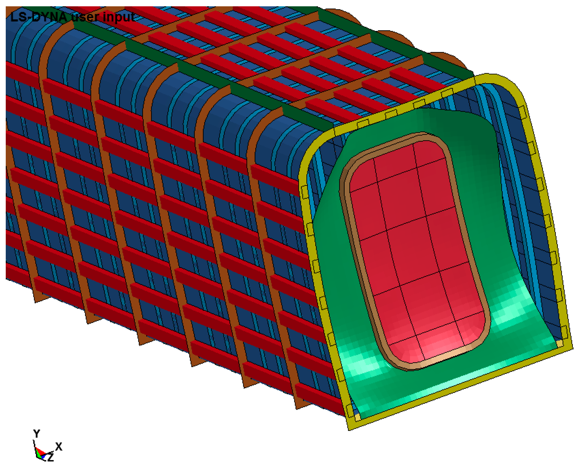
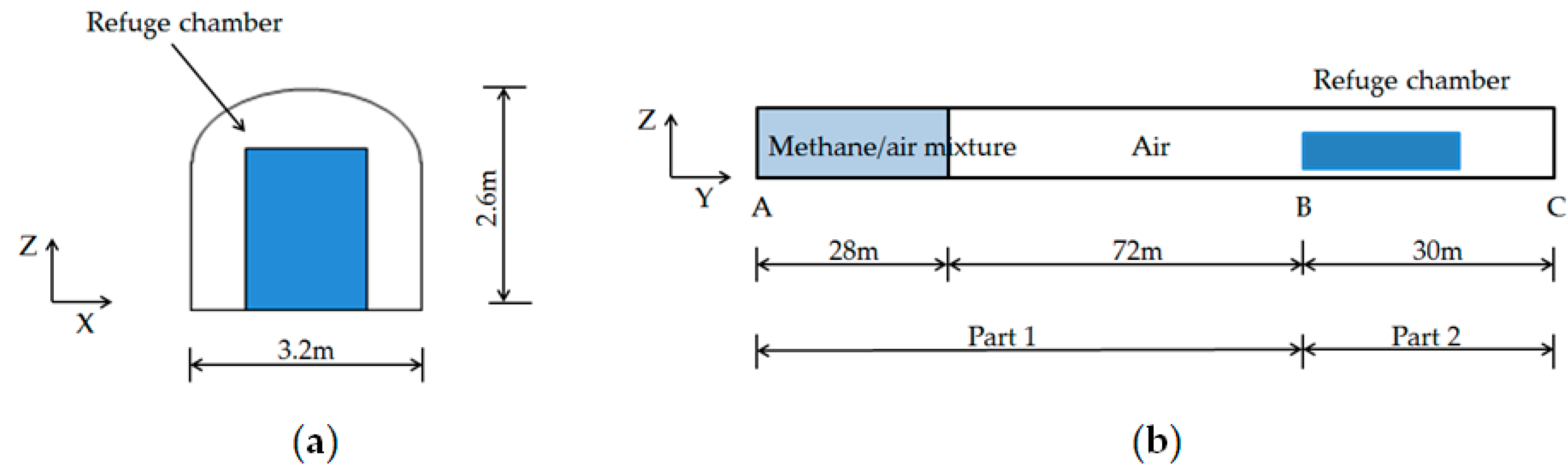
2.2. Model Description

The finite element model of the actual refuge chamber is established as shown in Figure 1. The refuge chamber model consists of 20 units. The intermediate section of the unit is composed of the steel plate and the edge of the unit consists of a flange. These units form a whole refuge chamber through bolting the flange and welding stiffeners together. Due to each part of the refuge chamber suffering from different blast loads, the bulkhead of the refuge chamber model is made of ordinary Q235-B steel, and the front door and stiffeners are made of Q345-B. Q460-B is used as material for other parts. In order to obtain different failure modes, different design parameters of the refuge chamber are used, as shown in Table 1.
Figure 2 shows that the underground mine tunnel is simulated as a semi-enclosed pipe model. One end of the tunnel is closed and the other is open. The tunnel is composed of two main parts. It includes the methane/air mixture zone and an air zone as Part 1 (from A to B), and the front section of the refuge chamber to the exit of the tunnel as Part 2 (from B to C). The length of the methane/air mixture zone is 28 m. This area is full of a gas/air mixture as the explosion source. The adjacent air zone is made for explosion shockwave propagation. The explosion shockwaves pass through Part 1 and finally affect the refuge chamber. The bottom section of the actual refuge chamber is fixed to the ground. It is supposed that there is no initial velocity of the refuge chamber. In order to simplify the calculation, the tunnel wall is simulated as smooth and rigid.

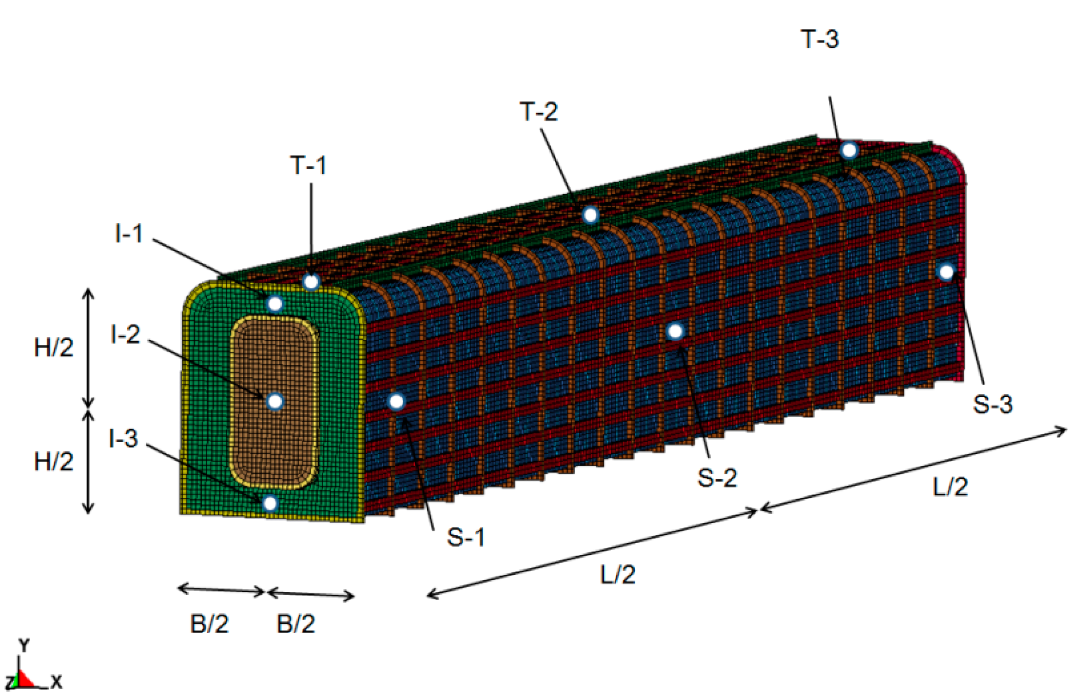
2.3. Modeling Approaches

Considering the thickness factor of different parts in the refuge chamber model, the SOLID164 element is selected to simulate cabin door, methane/air mixture and air, and the SHELL163 element is selected to simulate cabins and flanges. The size of the shell and solid elements which are used to simulate the refuge chamber are 40 mm, and the size of the solid elements which are used to simulate methane/air mixture and air is 160 mm. A coupling algorithm is employed to simulate the fluid-structure interaction. The fluid, such as a methane/air mixture and air, adopts an ALE fixed/mobile mesh method and the refuge chamber structure adopts a Lagrangian deformable mesh method. The coupling forces at the fluid-structure (the air and the refuge chamber) interface are computed by the coupling algorithm. Through an explicit finite element method, the coupling forces are, respectively, added to the fluid and the structure nodal forces. In order to obtain the local peak pressure on the refuge chamber structure, an accurate fluid-structure coupling algorithm is needed.

2.4. Material Models and Equation of State

One of Chinese coal mine safety code manuscripts, “Specifications for mine mobile refuge chambers”, refers that the explosive source is a high-pressure gas, such as methane/air mixture, with the initial volume of 200 m3 at the end of the tunnel. To simulate the propagation of the shockwave generated by instantaneous detonation of the source and its impact on the refuge chamber, the specifications state that the blast wave pressure on the front surface of the refuge chamber which is 100 m away from the explosive source is not less than 0.6 MPa.
A null material model and linear polynomial equation of state are used to describe the characteristics of air and gas/air mixture. The following equation is the linear polynomial equation of state:
P = C 0 + C 1 μ + C 2 μ 2 + C 3 μ 3 + ( C 4 + C 5 μ + C 6 μ 2 ) E
where, ρ 0 is the initial density, ρ is current density, E is the internal energy. C0C6 are state parameters of the Equation (1), μ = ρ ρ 0 1 . The main parameter values of the null material model and linear polynomial equation of state are shown in Table 2 [12,21,22].
The mechanical properties of steel are affected noticeably at a high strain rate. The strain rate effect of steel must be taken into account under the explosion. Previous studies have shown that the yielding strength of the most strain rate-sensitive materials will increase substantially under a high strain rate [23]. In this paper, the plastic-kinematic mode (MAT_03 in LS-DYNA) and the Von-Miss yielding criterion are used to simulate the steel material, and the rate-dependent plasticity model of yielding stress, put forward by Cowper and Symonds [24]:
σ d y = [ 1 + ( ε p l · γ ) m ] σ y
where, σdy is the dynamic yielding strength considering strain rate effect, σy is the static yielding strength, ε p l · is the equivalent plastic strain rate, γ is the viscosity parameter, m is the strain-rate hardening parameter. The suggested values of γ and m for steel are 40.4 s−1 and 0.5 [23]. The main parameter values of the steel materials in this paper are shown in Table 3.

3. Simulation Results and Discussion

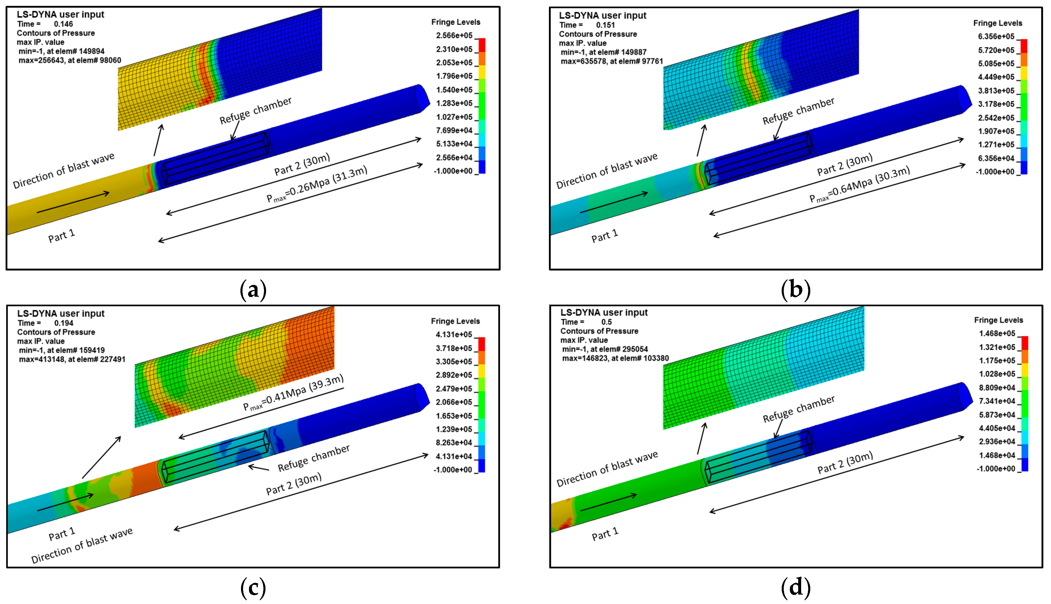
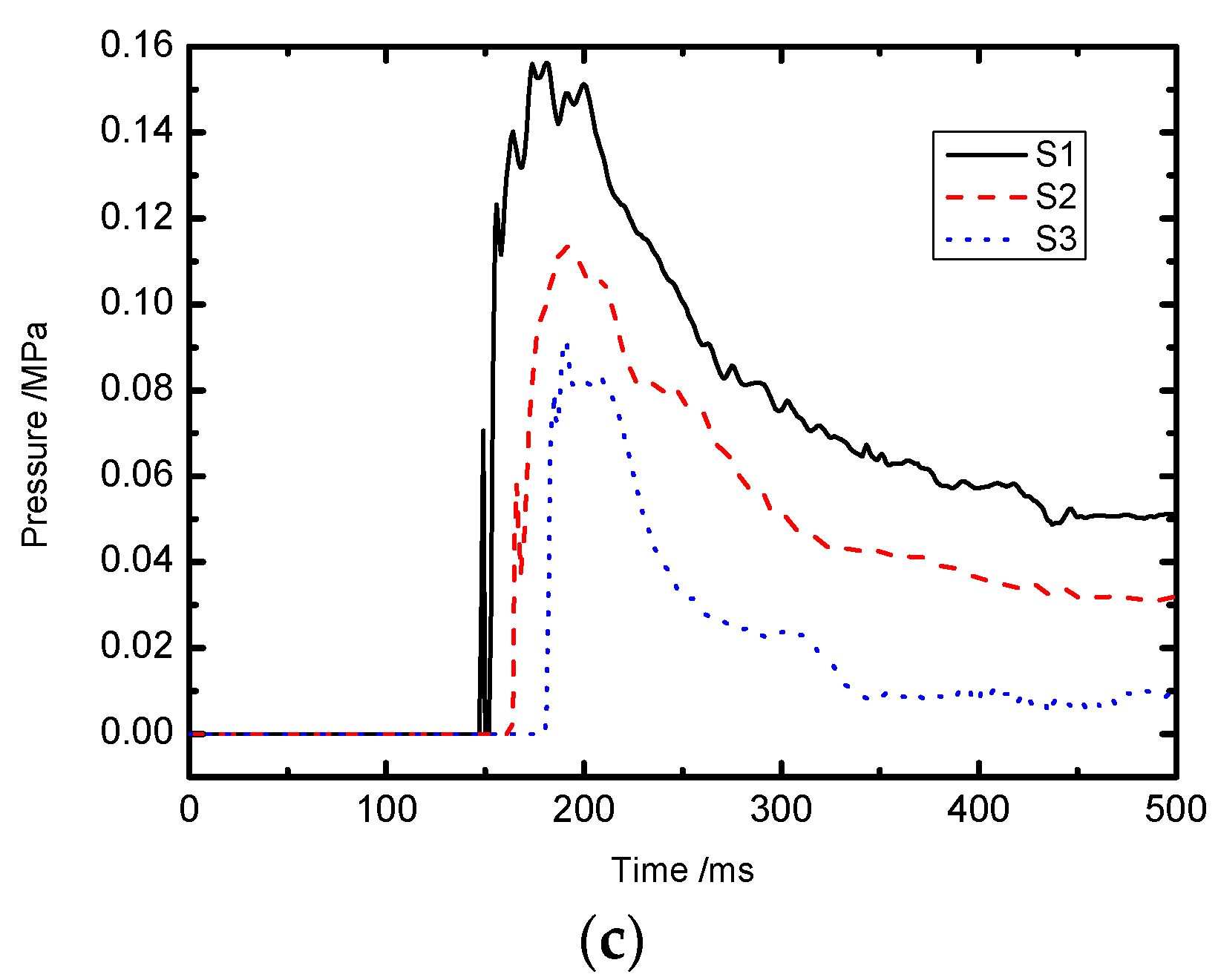
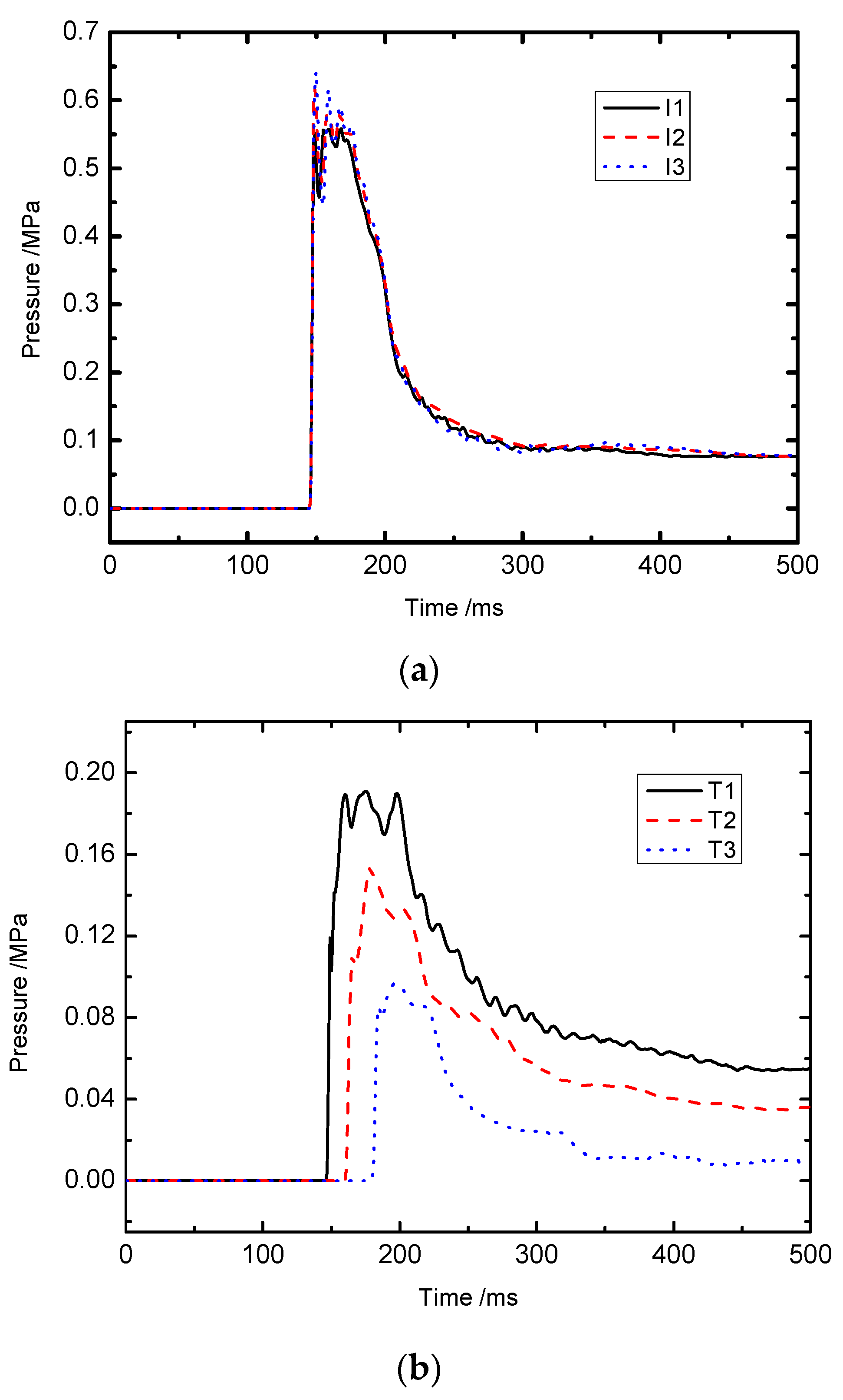
3.1. Fluid-Structure Interaction Effect

Pressure contours caused by the explosive shock wave at various instants during propagation are shown in Figure 3. The gas is detonated at an initial time and the explosive shockwaves expand quickly from one end of the tunnel to the front surface of the chamber. Before the shockwave reaches the chamber, the peak pressure value of the incident wave is about 0.26 MPa at 146 ms (in Figure 3a). As the shockwave reaches the chamber, the peak pressure increase rapidly and the value is about 0.64 MPa at 151 ms (in Figure 3b). This is because of the sudden interaction between the incident wave and the reflected wave. Then, the pressure immediately decreases due to the energy of shockwave absorption by the refuge chamber, multiple reflections, and diffractions by the tunnel wall. At 194 ms, the peak pressure on the chamber decreases to 0.41 MPa (in Figure 3c). Then, the pressure on chamber gradually reduces and closes to a nearly constant value of 0.15 MPa (in Figure 3d).
In order to obtain the pressure distribution of the shockwave by a gas explosion on each surface of the refuge chamber structure, some testing points are selected on the front, side, and top surfaces of the refuge chamber, respectively. Figure 4 shows the locations of each testing point. Figure 5 shows the pressure-time curves obtained from different testing points. In Figure 5a, the pressure value at the front surface of the refuge chamber reaches a maximum of 0.64 MPa at 150 ms. Figure 5b,c show that the peak pressure on the side and upper surface gradually reduce along the distance and the pressure value which is measured close to the front ranged between 0.15 and 0.19 MPa is almost 1/3 of that on the front surface. Since the shockwave diffracts around the refuge chamber, a secondary peak pressure occurs.

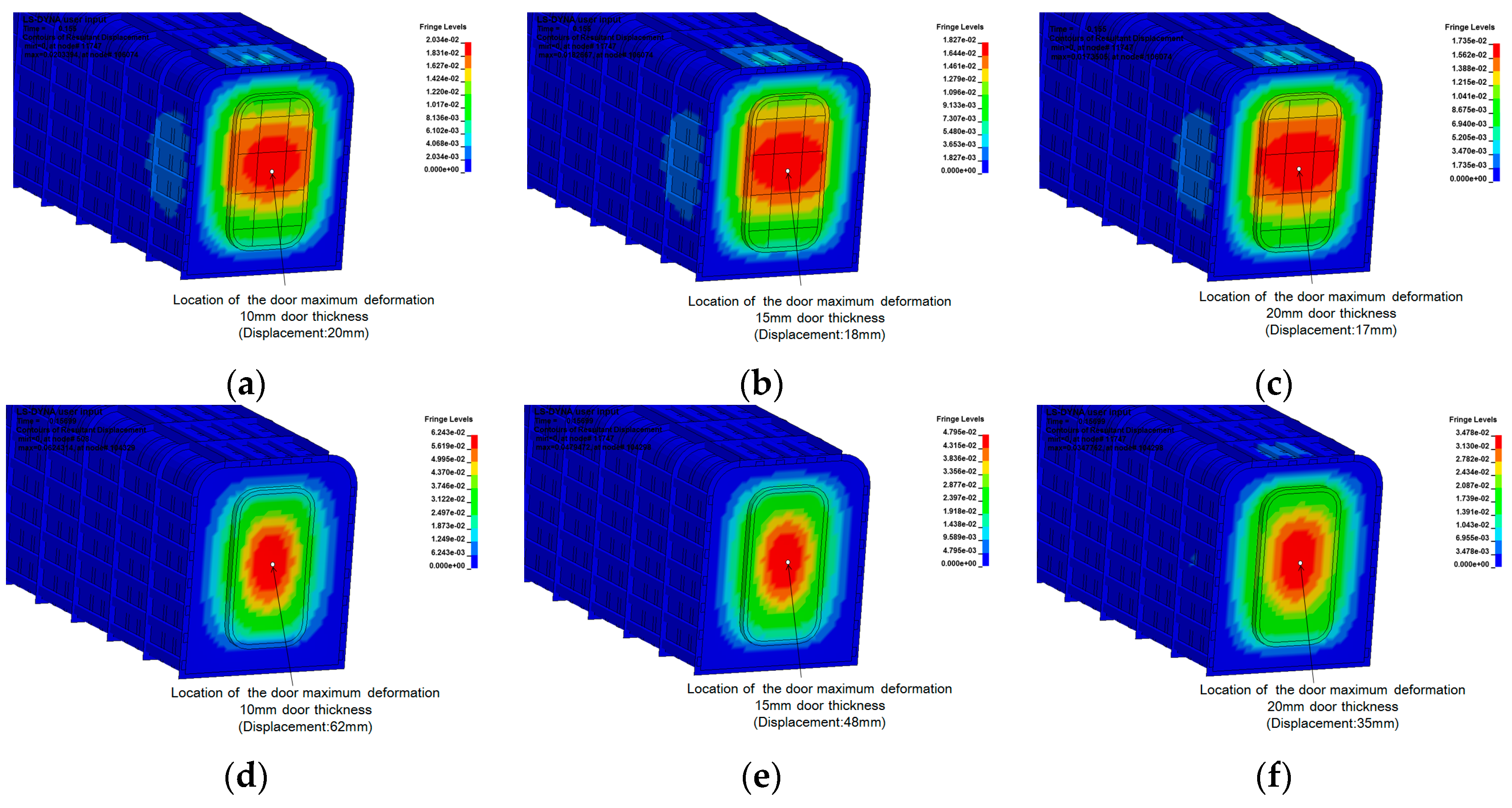
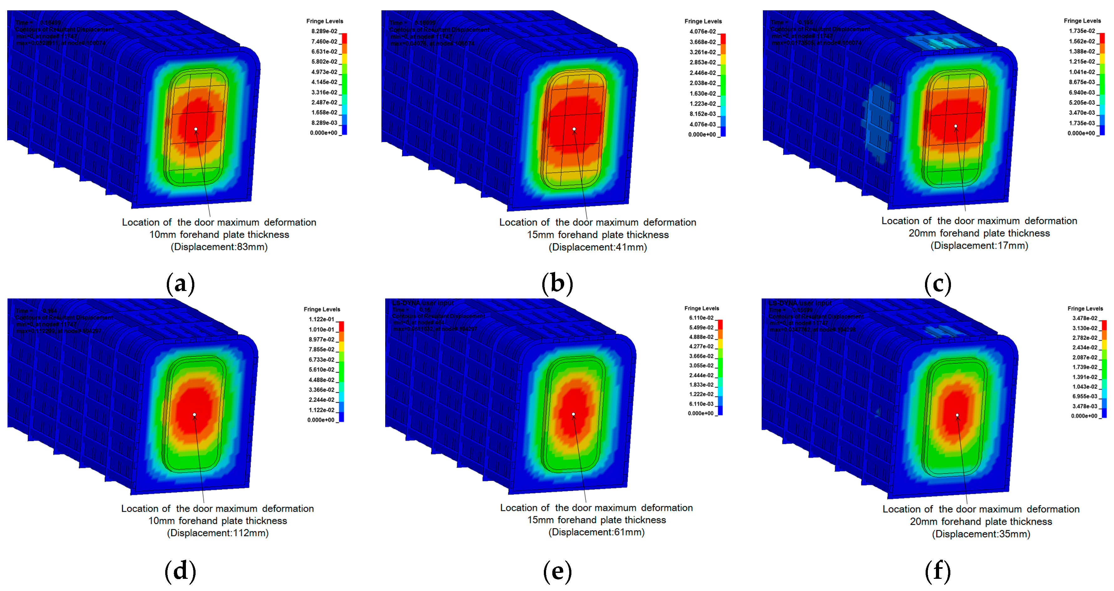
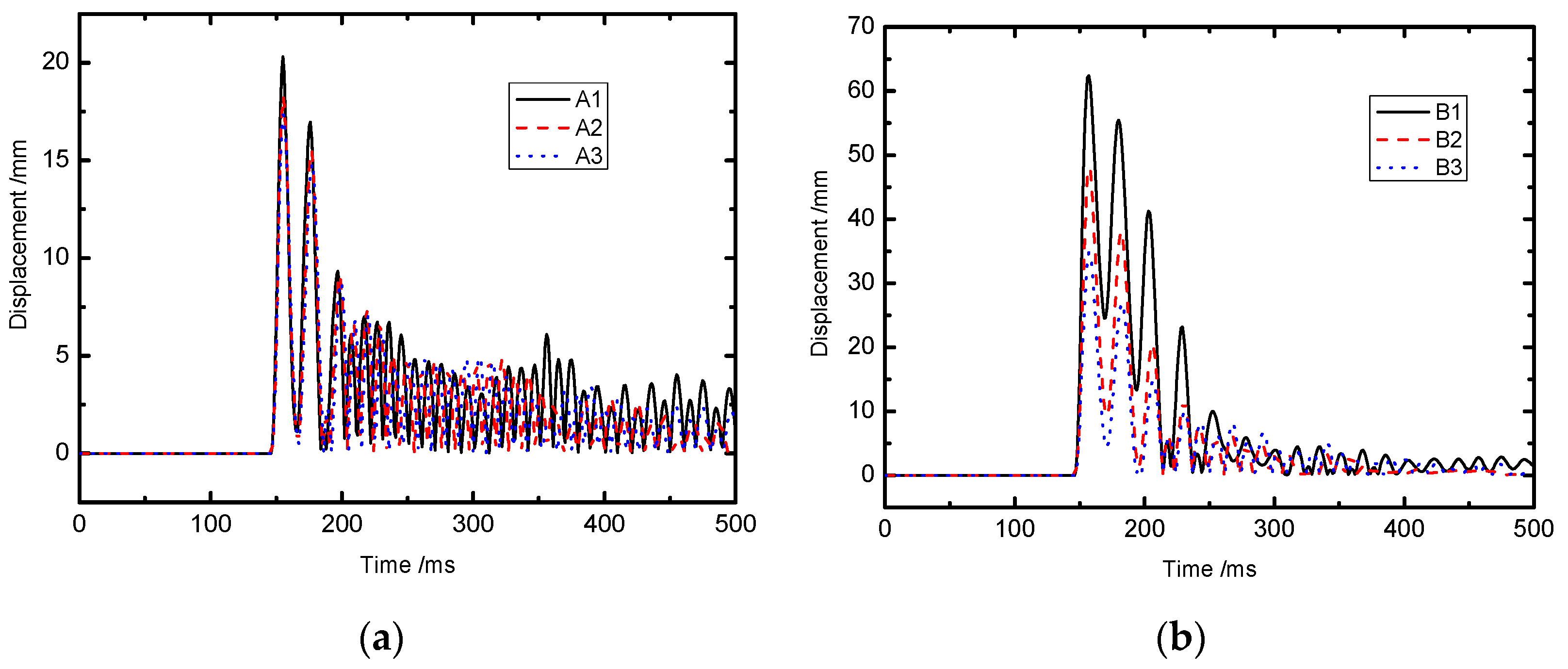
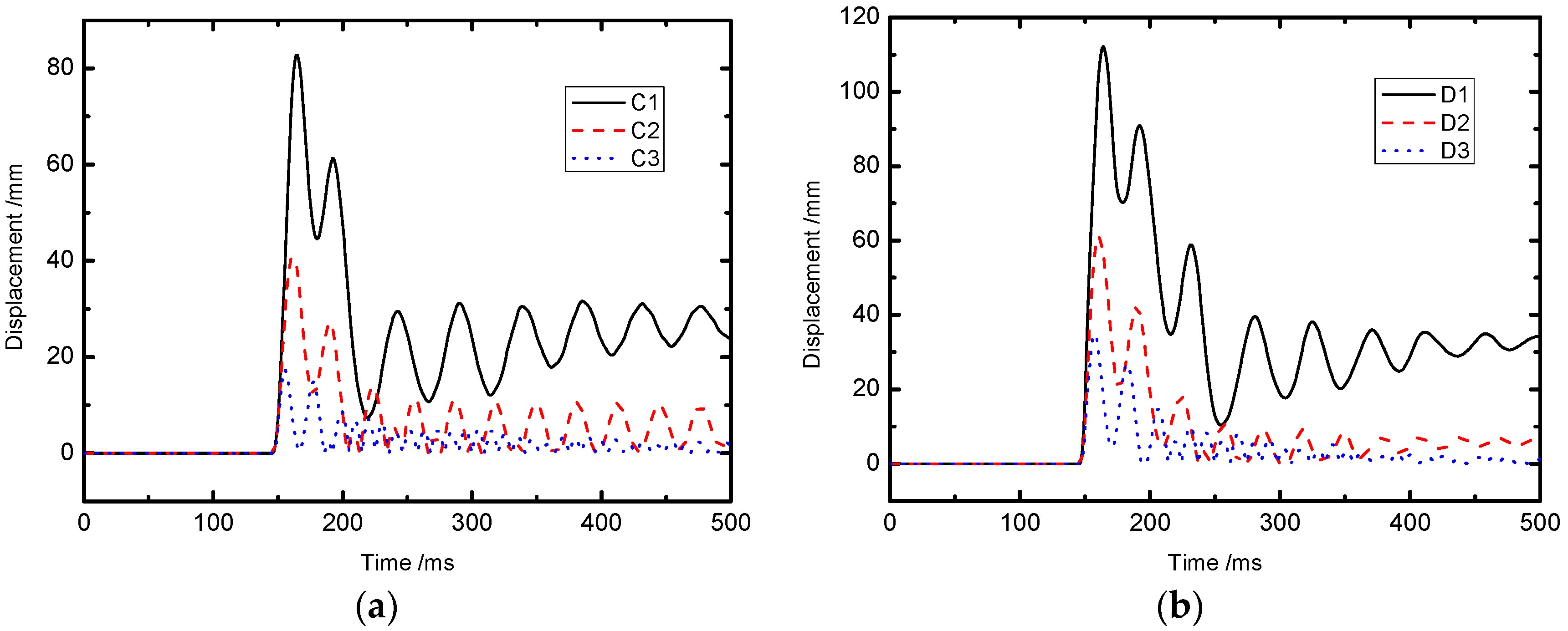
3.2. Failure Mode of Refuge Chamber Structure

The impact of the destruction occurred in different components of the refuge chamber is analyzed in this study. The front door and the connection of the front door are selected for analysis and its impact on the form and extent of damage that may occur in the refuge chamber.

(a) Failure mode I

The front door is the first structural component suffering the blast shockwave. With the propagation of the shockwave, the peak pressure value of the shockwave is decreased as the energy of the shockwave is absorbed by the refuge chamber. Therefore, the deformation of the front door of the refuge chamber is the most severely deformed structural component. After the application of a strong blast shockwave, remarkable extrusion and dents can be observed in the front door and the largest deformation is found at the center of the front door.
In this section, the arrangement of the cabin door stiffeners of the refuge chamber on the influence of the door deformation is analyzed. The deformation of the door with different thicknesses is considered in both cases, which are a door with stiffeners and a door with no stiffeners, as Figure 6 shows. From the comparison charts it can be seen that the effect of stiffeners on the door is obvious. The thickness of the door has minimal impact on the peak deformation. The peak deformation values of the door center with three different thicknesses are in the range of 17–20 mm. Moreover, the peak deformation of the door with no stiffeners is greatly affected by the thickness of the door. The peak deformation of the door with no stiffeners will decrease markedly with the increase of the thickness of the door. The peak deformation values of the door center with three different thicknesses are in the range of 35–62 mm. There is no residual deformation of the door in both cases. The peak deformation values of the door with no stiffeners are a 106%–210% increase over the door with stiffeners. Figure 7 shows the deformation contour of the doors with different thicknesses.
Additionally, the deformation of the door with different forehand plate thicknesses is also considered in both cases, which are the door with stiffeners and the door with no stiffeners, as Figure 8 shows. Similar to the results of the last section, the effect of stiffeners on the door is obvious. The difference is that the peak deformation and the residual deformation of the door are affected by the thickness of the forehand plate, regardless of whether the door has stiffeners. The peak deformation will decrease, marked with the increase of the thickness of the forehand plate. In the case of the door with stiffeners, the peak deformation values of the door center with three different forehand plate thicknesses are in the range of 17–83 mm and the maximum residual deformation is 24 mm. In the case of the door with no stiffeners, the peak deformation values of the door center with three different forehand plate thicknesses are in the range of 35–112 mm and the maximum residual deformation is 34 mm. The peak deformation values of the door with no stiffeners are a 35%–106% increase over the door when reinforced. The maximum residual deformation value of the non-reinforced door is a 42% increase over the door with stiffeners. Figure 9 shows the deformation contour of the doors with different forehand plate thicknesses. The structure of the refuge chamber was in a plastic state. The peak deflection values are already beyond the safety requirement in the “specifications for mine mobile refuge chambers” manuscript in China (20 mm or 2% deflection). Thus, failure mode I is the unrecoverable extrusion large deformation.

(b) Failure mode II

The front door and bulkhead are connected by welds, using the connecting element to simulate the real weld situation. As is shown in Figure 10, in the event of a strong explosion shockwave, the upper portion of the front door detaches from the bulkhead and the refuge chamber becomes invalid.
The connecting element (weak material property) between the front door and bulkhead is established to simulate the condition when the connection strength is low. The front door detaching from the bulkhead might become the third failure mode. However, further research is needed to simulate the real weld condition.

4. Conclusions

In this paper, the explosive shock wave propagation and dynamic behaviors of a coal mine mobile refuge chamber under the gas explosion were simulated and analyzed by using the explicit nonlinear dynamic finite element program ANSYS/LS-DYNA and the ALE numerical calculation method. The numerical model included an underground mine tunnel, a coal mine mobile refuge chamber, and the gas/air mixture. The following conclusions were reached:
The phenomenon of interaction between the chamber and shockwave was pronounced. The propagation of shock waves and the affection to the chamber could be successfully simulated by ALE fluid-structure interaction method. The shockwave is reflected by the chamber and the reflected wave pressure value on the front surface of the chamber is about twice higher than the incident one. The peak pressure on the side and upper surface gradually reduces along the distance and the value which measured close to the front ranged between 0.15 and 0.19 MPa is almost 1/3 of that in the front surface.
Based on the simulation results, there are two failure modes of the refuge chamber; one is the unrecoverable extrusion large deformation of the front door, the other is the front door detaching from the bulkhead. The front door is the first component that bears the blast shockwave, and it is the most easily damaged part. The deformation is effectively controlled by increasing the thickness of the door and stiffeners. When welding is weak, the upper portion of the front door may detach from the bulkhead, and the refuge chamber becomes invalid. Therefore, in order to ensure the refuge chamber safety, some measures such as increasing the thickness of the door and stiffeners and strengthening the welding between the door and the bulkhead are suggested.

Acknowledgments

The authors thank the financial support of the National Natural Science Foundation of China (Grant No. 51108141) and Natural Science Foundation of Heilongjiang Province of China (Grant No. QC2011C064) for carrying out this research.

Author Contributions

Boyi Zhang and Wei Wang conceived and designed the simulation research; Dongxian Zhai set up the simulation models; Boyi Zhang and Dongxian Zhaianalyzed the data; Boyi Zhang and Dongxian Zhai wrote the paper.

Conflicts of Interest

The authors declare no conflict of interest.

References

  1. Wang, S.; Jin, L.Z.; Li, J. The present statns of overseas mine emergency refuge chamber technology. J. Saf. Sci. Technol. 2010, 6, 119–123. (In Chinese) [Google Scholar]
  2. Yang, D.M. The construction and development of the emergency refuge system in coal mine. Coal Sci. Technol. 2010, 11, 6–9. (In Chinese) [Google Scholar]
  3. Mitchell, M.D. Analysis of Underground Coal Mine Refuge Shelters. Ph.D. Thesis, West Virginia University, Morgantown, WV, USA, 20 April 2008. [Google Scholar]
  4. Sun, J.P. The function and configuration scheme in coal mine. Ind. Mine Autom. 2010, 11, 1–4. (In Chinese) [Google Scholar]
  5. Safety, M. Health administration, US department of labor. 30 CFR parts 7 and 75 refuge alternatives for underground coal mines final rule. Natl. Arch. Rec. Adm. 2008, 82, 18–20. [Google Scholar]
  6. Si, R.J. Research on Coal Mine Gas and Coal Dust Explosion Propagation Law. Ph.D. Thesis, Shandong University of Science and Technology, Tsingtao, China, 5 March 2007. [Google Scholar]
  7. Jian, C.G.; Lin, B.Q.; Zhai, C. Research on structure changes of shock wave during gas explosion. J. China Univ. Min. Technol. 2003, 32, 363–366. (In Chinese) [Google Scholar]
  8. Li, F.W.; Jin, L.Z.; Zhan, Z.N. Numerical simulation study of air distribution law of air pressure system in the mine refuge chamber. J. Theor. Appl. Inf. Technol. 2012, 45, 205–211. [Google Scholar]
  9. Zhao, H.J.; Qian, X.M. Simulation analysis on structure safety of two typical refuge chamber shell forms under explosion load. Procedia Eng. 2012, 5, 910–915. [Google Scholar] [CrossRef]
  10. Zhao, H.J.; Qian, X.M.; Li, J. Simulation analysis on structure safety of coal mine mobile refuge chamber under explosion load. Saf. Sci. 2012, 50, 674–678. [Google Scholar] [CrossRef]
  11. Li, Y.M.; Wu, W.T. Design of integrated protective performance test platform for coal mine portable hardware. Autom. Ind. Min. 2012, 4, 64–66. (In Chinese) [Google Scholar]
  12. Zhang, B.Y.; Zhao, W.; Wang, W.; Zhang, X.H. Pressure characteristics and dynamic response of coal mine refuge chamber with underground gas explosion. J. Loss Prev. Process Ind. 2014, 30, 37–46. [Google Scholar] [CrossRef]
  13. Mei, R.B.; Li, C.S.; Cai, B.; Liu, X.H. Finite element analysis of the antiknock ability of the coal mine refuge chamber under explosion finite element. J. Northeast. Univ. 2013, 1, 85–94. (In Chinese) [Google Scholar]
  14. Xu, Y.; Cui, J.K.; Han, Y.; Li, R. Structure optimization of removable hardware mine refuge chamber. Saf. Coal Mines 2012, 43, 81–83. (In Chinese) [Google Scholar]
  15. Ma, L.D.; Pan, H.Y.; Wang, Y.; Meng, Z.J. Numerical simulation of explosion shock resistance of the underground refuge chamber. J. Vib. Shock. 2012, 20, 172–176. (In Chinese) [Google Scholar]
  16. Zeng, Y.Y.; Bai, C.H.; Li, J.P.; Chen, J.; Wang, Z.Q. Numerical simulation of anti-impact of the refuge chamber in the tunnel. J. China Coal Soc. 2010, 37, 1705–1708. (In Chinese) [Google Scholar]
  17. Zhao, H.J.; Huang, P.; Qian, X.M. Structure safety analysis and optimization of refuge chamber shell under explosion load. J. China Coal Soc. 2013, 38, 1095–1100. (In Chinese) [Google Scholar]
  18. Fan, X.T. Study on blast performance of refuge chamber. Min. Saf. Environ. Prot. 2010, 37, 25–30. [Google Scholar]
  19. Jia, Z.W.; Jing, G.X.; Cheng, L. Study on propagation regulation about shock wave of gas explosion at laneway area break. China Saf. Sci. J. 2007, 17, 92–94. [Google Scholar]
  20. LSTC. LS-DYNA Keyword User’s Manual Version 971; Livermore Software Technology Corporation: Livermore, CA, USA, 2007. [Google Scholar]
  21. Tabatabaei, Z.S.; Volz, J.S. A Comparison between Three Different Blast Methods in LS-DYNA: LBE, MM-ALE, Coupling of LBE and MM-ALE. In Proceedings of the 12th International LS-DYNA Users Conference, Dearborn, MI, USA, 3–5 June 2012.
  22. Lu, S.Z. Research on failure mechanism of large-scale steel oil storage tanks under combustible gas blast. Harbin Inst. Technol. 2014, 46, 23–30. (In Chinese) [Google Scholar]
  23. Liew, J.Y.R. Survivability of steel frame structures subject to blast and fire. J. Constr. Steel Res. 2008, 64, 854–866. [Google Scholar] [CrossRef]
  24. Cowper, G.R.; Symonds, P.S. Strain-Hardening and Strain-Rate Effects in the Impact Loading of Cantilever Beams; Brown University: Providence, RI, USA, 1957. [Google Scholar]
Figure 1. Schematic diagram of the refuge chamber model.
Applsci 06 00145 g001
Figure 2. The cross-section and longitudinal section area of the tunnel. (a) Cross-section of the tunnel; (b) Longitudinal section area of the tunnel.
Applsci 06 00145 g002
Figure 3. Pressure contour during the blast wave propagation in the tunnel. (a) t = 146 ms; (b) t = 151 ms; (c) t = 194 ms; (d) t = 500 ms.
Applsci 06 00145 g003
Figure 4. The distribution of testing points.
Applsci 06 00145 g004
Figure 5. Pressure-time curve on different surfaces. (a) Front surface; (b) Top surface; (c) Side surface.
Applsci 06 00145 g005aApplsci 06 00145 g005b
Figure 6. Maximum displacement-time curves with different front door thicknesses. (a) Door with stiffeners and (b) door with no stiffeners.
Applsci 06 00145 g006
Figure 7. Maximum deformation of the door with different thicknesses. (a) A1; (b) A2; (c) A3; (d) B1; (e) B2 and (f) B3.
Applsci 06 00145 g007
Figure 8. Maximum displacement-time curves with different forehand plate thicknesses. (a) Door with stiffeners and (b) door with no stiffeners.
Applsci 06 00145 g008
Figure 9. Maximum deformation of the door with different forehand plate thicknesses. (a) C1; (b) C2; (c) C3; (d) D1; (e) D2 and (f) D3.
Applsci 06 00145 g009
Figure 10. Process of the front door detaching from the bulkhead.
Applsci 06 00145 g010
Table 1. Design parameters used in the refuge chamber.
Failure ModeSpecimen NumberFront Door StiffenersFront Door Thickness (mm)Forehand Plate Thickness (mm)Connecting Element
Failure mode IA1Yes1020No
A215
A320
B1No1020No
B215
B320
C1Yes2010No
C215
C320
D1No2010No
D215
D320
Failure mode IIEYes2020Yes
Specimen A3 is the same as specimen C3 and specimen B3 is the same as Specimen D3.
Table 2. Parameters of linear polynomial equation of state.
MaterialDensity (kg/m3)C0 (Pa)C1C2C3C4C5C6E (J/m3)V0
Air1.29−1.0 × 1050000.40.402.5 × 1051.0
Methane/air mixture1.23500000.2740.27403.408 × 1051.0
Table 3. Parameters of steel materials.
SteelElastic Modulus (MPa)Poisson’s Ratio μDensity ρ (Kg/m3)σy (MPa)γ (s−1)mTangent Modulus Etan (MPa)Failure Strain
Q235-B2.0 × 1050.3785023540.40.52.0 × 1030.2
Q345-B2.0 × 1050.3785034540.40.52.0 × 1030.2
Q460-B2.0 × 1050.3785046040.40.52.0 × 1030.2

