Article

Real-Time Compensation for Thermal Errors of the Milling Machine

1
Department of Mechanical Engineering, National Chin-Yi University of Technology, Taichung 41170, Taiwan
2
Ph.D. Program, Graduate Institute of Precision Manufacturing, National Chin-Yi University of Technology, Taichung 41170, Taiwan
*
Author to whom correspondence should be addressed.
Appl. Sci. 2016, 6(4), 101; https://doi.org/10.3390/app6040101
Submission received: 30 November 2015 / Revised: 25 March 2016 / Accepted: 28 March 2016 / Published: 7 April 2016

Abstract

:
This paper is focused on developing a compensation module for reducing the thermal errors of a computer numerical control (CNC) milling machine. The thermal induced displacement variations of machine tools are a vital problem that causes positioning errors to be over than 65%. To achieve a high accuracy of machine tools, it is important to find the effective methods for reducing the thermal errors. To this end, this study first used 14 temperature sensors to examine the real temperature fields around the machine, from which four points with high sensitivity to temperature rise were selected as the major locations for creating the representative thermal model. With the model, the compensation system for controlling the displacement variation was developed. The proposed model has been applied to the milling machine. Current results show that the displacement variations on the x- and y-axes and the position error at the tool center were controlled within 20 µm when the compensation system was activated. The feasibility of the compensation system was successfully demonstrated in application on the milling operation.

Graphical Abstract

1. Introduction

Position accuracy is one of the critical performance factors affecting the machining precision of machine tools in operation. According to the studies [1,2], thermal deformations may be responsible for 40%–70% of geometrical inaccuracies of machine tools. To reduce the influence of the thermal induced errors, some techniques associated with the compensation schemes have been developed and implemented in the machine tools, including implementation of thermally symmetrical machine design [3,4,5], the introduction of additional cooling systems [6,7] and thermal deformation compensation [8,9,10]. Although optimization designs of machine tool structure are an effective way to reduce thermal errors, thermal displacement cannot be completely avoided since the external and internal heat sources under varying operating conditions cannot be accurately predicted at the design stage. Compensation techniques are considered essential methods for reducing the positioning errors and hence increasing the working accuracy [11,12]. Thermal problems are more complicated than geometric problems because the temperature field of a machine tool changes constantly with the working cycle and the environmental conditions. The development of an effective thermal error compensation system greatly depends on the accurate prediction of the time-variant thermal errors. Most thermal error compensation studies have focused on the measurements of the thermal characteristics and then the establishment of thermal-induced error models with accurate prediction based on empirical approach [13,14,15]. Generally, the most common model for prediction of thermally induced displacements is obtained by multiple linear regressions [16,17]. Recently, different kinds of artificially intelligent approaches have also been applied to thermal error modeling in order to improve the accuracy and robustness of the error models. These artificial intelligence modeling techniques include artificial neural networks (ANNs) [18,19,20], fuzzy logic [19], adaptive neuro-fuzzy inference systems (ANFIS) [21] and integrations of the different modeling methods [22,23]. For example, Vanherck et al. [18] applied the artificial neural network model to approximate complex multivariable non-linear relationships and hence effectively compensated for the thermal deformation of multiple axes machine tools. Their results showed the maximum deformation was reduced from 150 µm to 15 µm, and the machining error was reduced from 75 µm to 16 µm through the application of the neural model. Horejša et al. [24] employed thermal transfer functions to develop an advanced thermal compensation in horizontal four-axis machine tools. Only four thermal sensors, instead of 21 original sensors, were used for calibration of measurements, which were found to decrease the error from 100 µm to 10 µm, and lessen the displacement error of the tool center point.
In more recent years, Abdulshahed et al. [22] proposed a novel method combining the ANFIS and grey system theory to predict thermal errors in machining. Basing on this method, they further developed accumulation generation operation (AGO) to simplify the modeling procedures, which were demonstrated to have a stronger prediction power than the standard ANFIS model. In another work [23], they integrated the adaptive neuro fuzzy inference system (ANFIS) with fuzzy c-means clustering method (FCM) to forecast thermal error compensation on computer numerical control (CNC) machine tools. Results of their studies show that the ANFIS-FCM model produced better performance, achieving up to 94% improvement in errors with a maximum residual error of ±4 µm.
Another important factor affecting the accuracy in thermal error modeling is the temperature variables, which are determined based on selection of appropriate locations for the temperature sensors. Basically, the location and number of sensors are determined based on engineering experience, often placing the sensors near the heat sources [25,26,27], or selecting them by using statistical techniques [28], and decomposition methods [29]. Generally, the optimum decisions in the location and numbers for temperature sensors are often not practical to machine users because of the different operating conditions in machining and environments of different machine. For this, Abdulshahed et al. [30] employed grey system theory to assess the influence weightings of all possible temperature sensors on the thermal response of the machine structure, which were further clustered into groups using the fuzzy c-means (FCM) clustering method. By this method, the number of temperature sensors was reduced from 76 possible locations to five, which significantly minimized the computational time, cost and effect of sensor uncertainty. In study of Abdulshahed et al. [31], they proposed a thermal model combining the Grey model GM(0, N) and the ANFIS model, and the temperature variables were recorded through the thermal imaging camera which had high pixel resolutions equating to 76,000 possible temperature measurement points, hence reducing the number of temperature locations to the equivalent of 525 points. This method can be applied to find the optimal location for temperature measurement when designing a thermal error control model.
In this study, thermal error model analysis and robust modeling were developed to control the thermal induced positioning error of a CNC milling machine. To create the thermal model, the locations of four thermal sensors were appropriately selected to establish the thermal displacement prediction model based on the initial measurements with the use of 14 sensors. Finally, the proposed compensation system was developed and implemented in a three-axis milling machine. The feasibility of the compensation system was validated through the application of milling operation.

2. Thermal Model of a Machine Tool
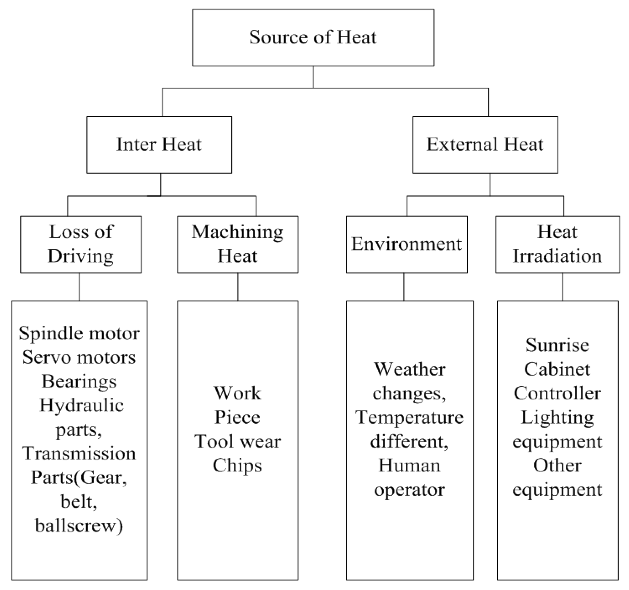
2.1. Basic Theory

There are three ways for transmitting the heat from one site to another in a structure.
  • Heat Conduction: heat can transfer from higher temperature to a lower one mainly by means of the solid medium, which can be described by following equation:
    q = k A d X d T
    where q is heat conduction, k is conduction factor of the medium, A is the area of contact surface, dX is the distance between the ends, and dT is the temperature difference between the ends.
  • Heat convection: heat is delivered naturally from one side to another by affecting the volume and density of the media, which can be described by the following equation:
    q = h A Δ T
    where q is heat convection, h is convection factor, A is sectional area, and ΔT is temperature difference between the ends.
  • Heat irradiation: Heat is delivered through electromagnetic wave, independent on any media, which can be described by following equation:
    q = σ A ( T 1 4 T 2 4 )
    where σ represents Stefan-Boltzmann constant, A is the radiating surface area, and T1 and T2 are the temperatures at two radiating surfaces.
Generally, there are three kinds of heat sources inducing the thermal deformation (Figure 1 and Figure 2). Firstly, the thermal deformation exists in the rotating spindle and ball-screw, which causes the thermal expansion of the internal components and hence the structure bending deformation of the machine tools. Secondly, there are errors of volume induced from structure construction in assembly error and between different mechanisms. Finally, errors of the controlled system are due to the interpolation errors of the CNC controller or errors of the servo system. These different kinds of errors should be overcome for precision manufacturing industry.

2.2. Thermal Model

Thermal error identification is one of the crucial steps for a successful thermal error modeling and compensation. It would be a practical thought that the deformations or displacement variations at certain points of machine tools due to thermal error can be obtained by measuring the temperature of the major points on the machine and other possible variables. However, it is a prerequisite to establish a compensation model about the thermal induced variation in displacement. Essentially, there are two methods for establishing the thermal model of the machine tool system [2,6].

2.2.1. Theoretical model

This method was implemented based on the numerical analysis through the finite element approach [5]. Generally, the temperature distributions of a milling machine are predicted based on differential formulas according to the heat transfer analysis. The thermal induced deformations are then calculated based on theory of elasticity through the finite element method. In this model, the determination of possible heat sources existing in different mechanism is prerequisite, but it is a difficult task to obtain the accurate data describing the heat flux generated in the various transmission components, which further results in the unrealistic model for thermal compensation.

2.2.2. Data-driven model

Generally, the thermal model can be practically established based on the collected parameters of the system by means of the different methods, including the statistics model, exponential function, multiple regression, non-linear multiple regression, neural networks, expert system and fuzzy theory.
In this study, the multiple linear regression analysis is employed to describe the correlation between axial deformation and temperatures. Regression analysis is characterized by the general form:
δ = E ( ε , Δ T 1 , Δ T 2 , ...... Δ T n )
The multiple linear regression is defined as a linear combination of several independent variables and one dependent variable in the form:
Y = β 0 + β 1 X 1 + β 2 X 2 + ............... + β k X k + ε
where βi, i = 0, 1, 2,… is the regression coefficient, ε is the total truncation errors. This system can also be written in matrix form:
[ Y ] = [ X ] [ β ] + [ ε ] y = β 0 + j = 1 k β j X i j + ε i
Y = [ y ( 1 ) y ( 2 ) y ( 3 ) . . . . y ( n ) ] = [ 1 x 1 ( 1 ) .... x k ( 1 ) 1 x 1 ( 1 ) .... x k ( 2 ) 1 x 1 ( 1 ) .... x k ( 3 ) . . . . . . . . . . . . 1 x 1 ( 1 ) x k ( n ) ] [ β 1 β 3 β 3 . . . . β k ]
In the above, the regression coefficients can be obtained by using the well known least-squares method.

3. Experiment Approach

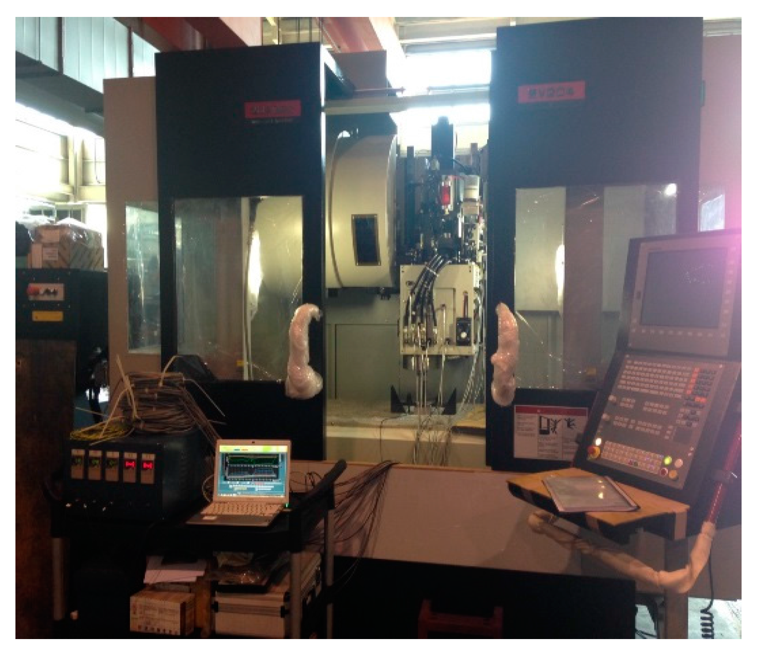
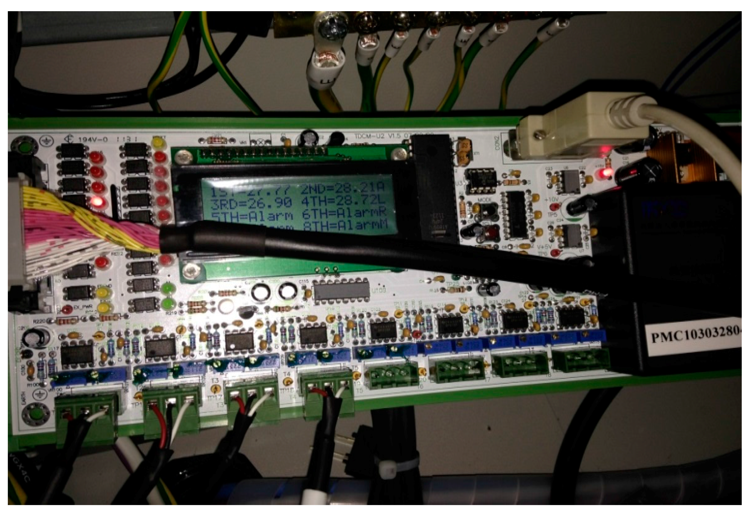
3.1. Experiment Setup

The milling machine used for experiment was made by the Quaser machine tool company (MV204C) (Taichung, Taiwan), as shown in Figure 3. The main specifications are: a spindle unit of 12,000 rpm, three axes linear guide modules (X, Y ball guides and Z roller guide), auto-lubrication system and Heidenhain 530 controller (Heidenhain, Berlin, Germany). Before creating the thermal model, it is necessary to realize the temperature distribution fields of the whole machine. This can also help to determine the critical points associated with the temperature fields dominating the thermal model of the machine.

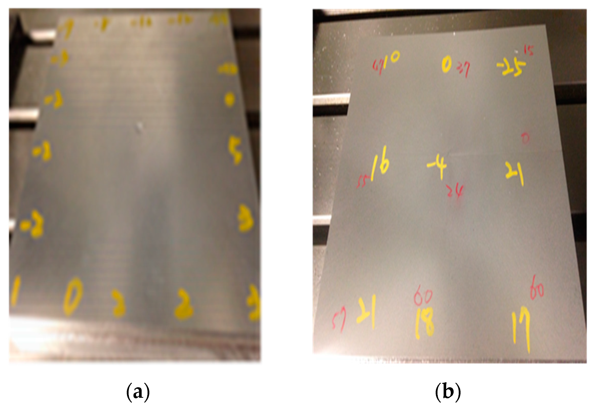
3.2. Initial Measurement

In precision machine tools, the main heat sources may come from the cutting process and the transmission mechanism. The heat generated in operation distributed among the workpiece, the chips, and the coolant. The majority of heat (60%–80%) is carried away by chips and eventually will be transferred to the coolant, while the heat sources in the feeding mechanism include the mechanical motion components and electrical driven components. Therefore, considering the milling machine used in this study, 14 temperature sensors were used to be placed at different locations, as shown in Figure 4, including the main heat sources, such as the spindle driven motor, and the other parts such as the vertical column and machine base where the heat can be conducted from heat sources. The measurement was performed for 48 h under spindle running at 7200 rpm. The temperature rises measured at the 14 points are illustrated in Figure 5. As expected, some major sites near the spindle bearings, transmissions belt and driven motor show significant temperature increments, which can be the candidates for the temperature variables in the thermal model.

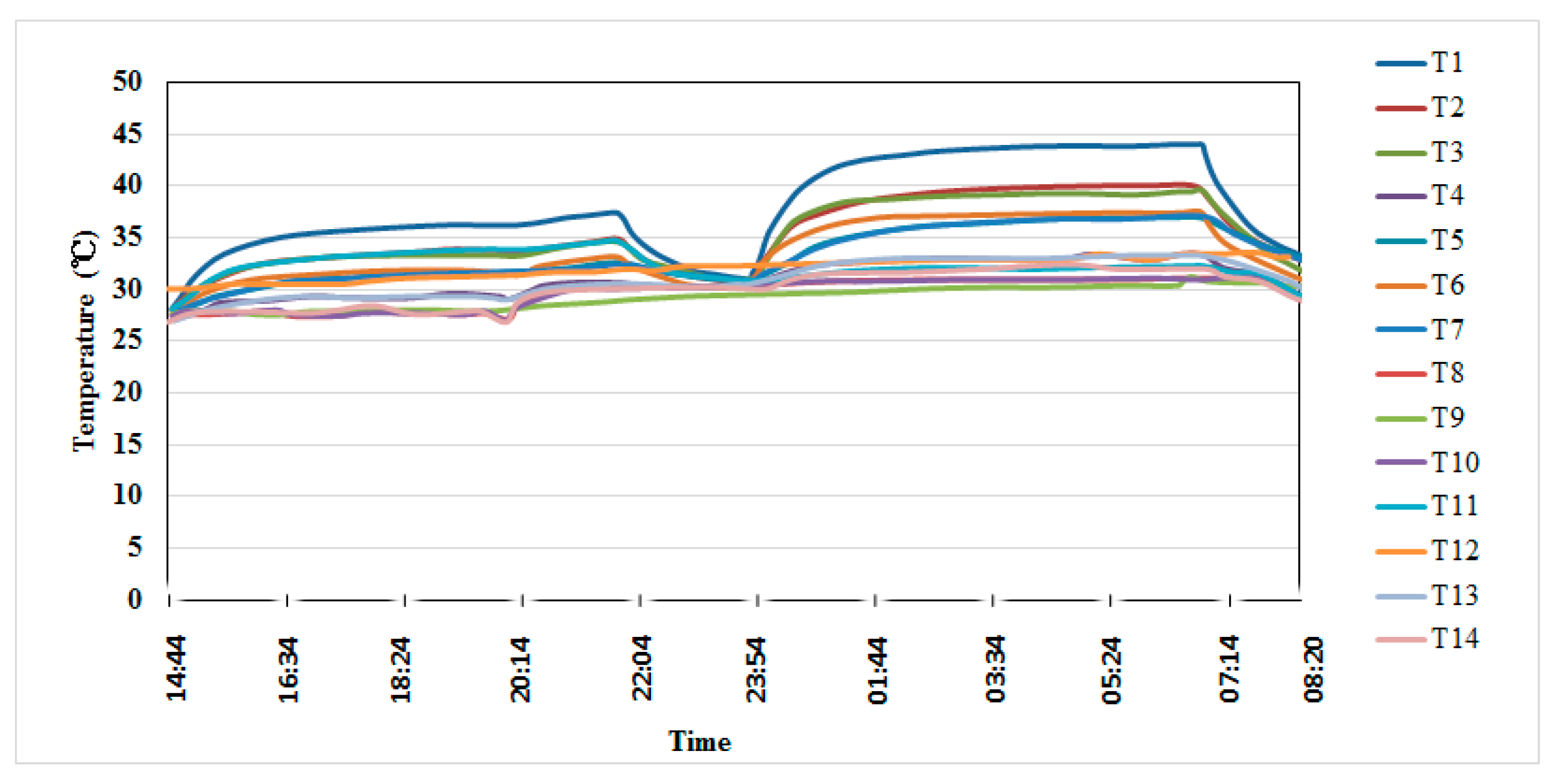
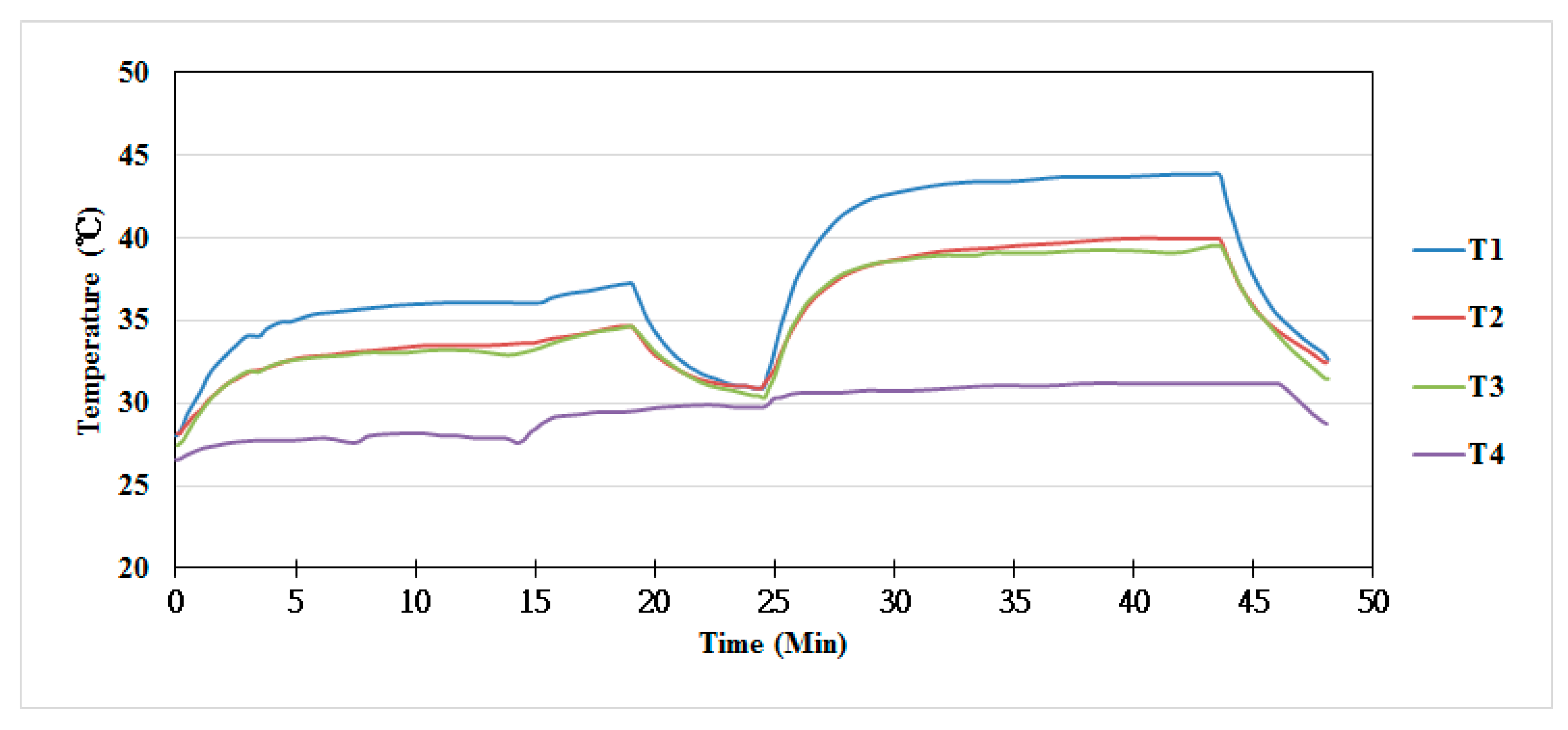
3.3. Measurement of Major Temperature Fields

After the initial measurement, three points were selected to be measured for creating the thermal model. In addition, the fourth point was located at the machine base to measure the environmental temperature as a reference to the temperature fields of the machine. As listed in Table 1, there are four sensors mounted on the machine to capture the required temperature data. The locations of the sensors are shown in Figure 6, in which T1 is located at the rear bearings of the spindle, T2 is located at the heat source of the belt transmission with greater frictional effect between belt and pulleys, T3 is located at spindle motor, T4 is mounted on the machine base where the temperature is controlled at around 28 °C. In addition, four non-contact displacemeters were used to detect the variations of the displacement of the working table along the x-, y- and z-axes (Figure 7). Formal measurement continued after the confirmation of the collecting data for 48 h of spindle running (7200 rpm and 10,800 rpm). The temperature rises measured at the four points are illustrated in Figure 8. From this figure, we can find that the temperatures measured at points around the spindle head vary significantly with the operating time of spindle, while the temperature variation at the machine base was insignificant. This can be ascribed to the fact that the machine was operated in a temperature-controlled environment, which also reduced the sensitivity of machine structural components to the environment’s temperature.

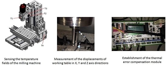
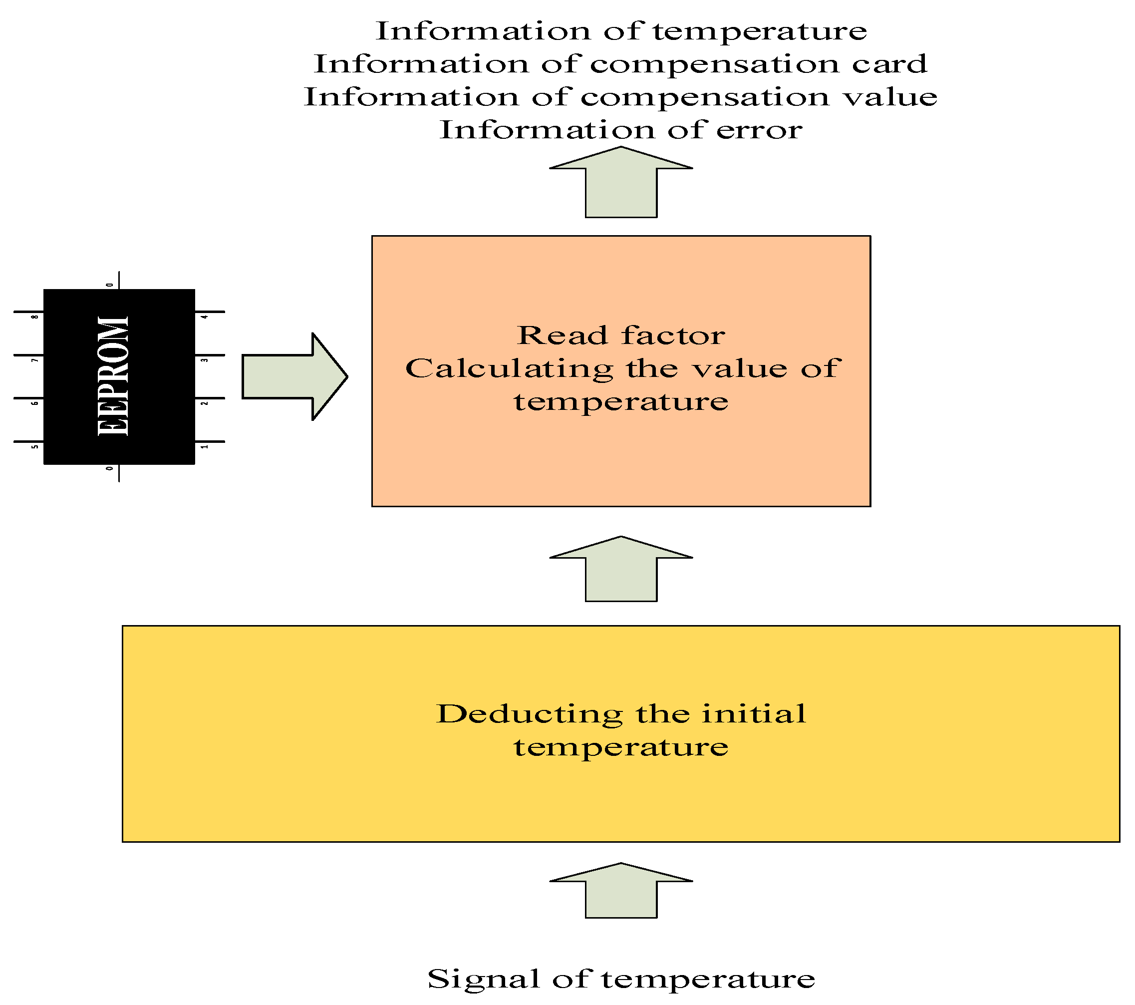
3.4. Application of Compensation Module

Following the above experiments, the thermal model was created based on the major temperature fields measured at the major points and the displacement variations of the working table. Then, the hardware module for compensation of thermal induced error was established, as shown in Figure 9, which mainly consists of the 8-bit microprocessor PIC18F6520 with 32 KB flash rom. The interactive communication and calculation for compensation protocol between data sensors and microprocessor was shown in Figure 10.
To verify the feasibility of the proposed thermal error compensation module in the practice of machining, this system was applied to investigate the positioning precision of the milling machine. The testing procedures are described briefly as follows:
(1)
Initial running of spindle for 48 h to ensure the measuring points on the machine tool, which can satisfy the desired temperature fields of thermal model.
(2)
Operating the spindle at 60% of full speed for 400 h—then, turning off the spindle and ensuring the x-y table and the spindle nose return to their initial positions.
(3)
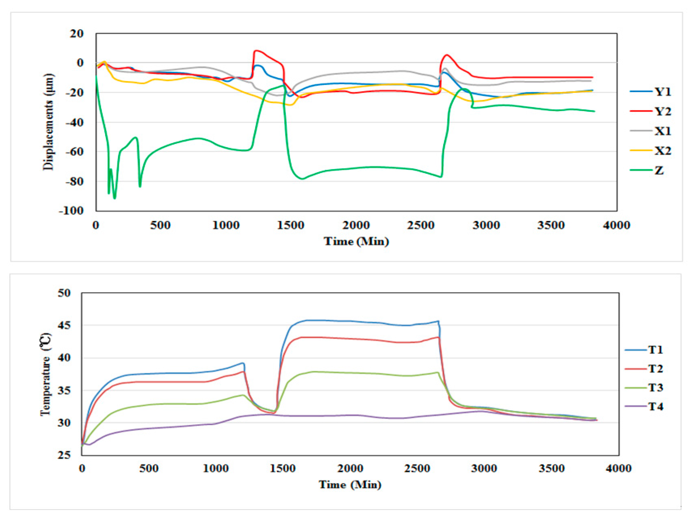
Performing the test by running the spindle at 90% of full speed for 400 h, in the meantime, recording the displacements of the table on the x- and y-axes and spindle nose on the z-axis.
(4)
Activating the compensation module to remove the displacement error due to temperature rise.

4. Results and Discussions

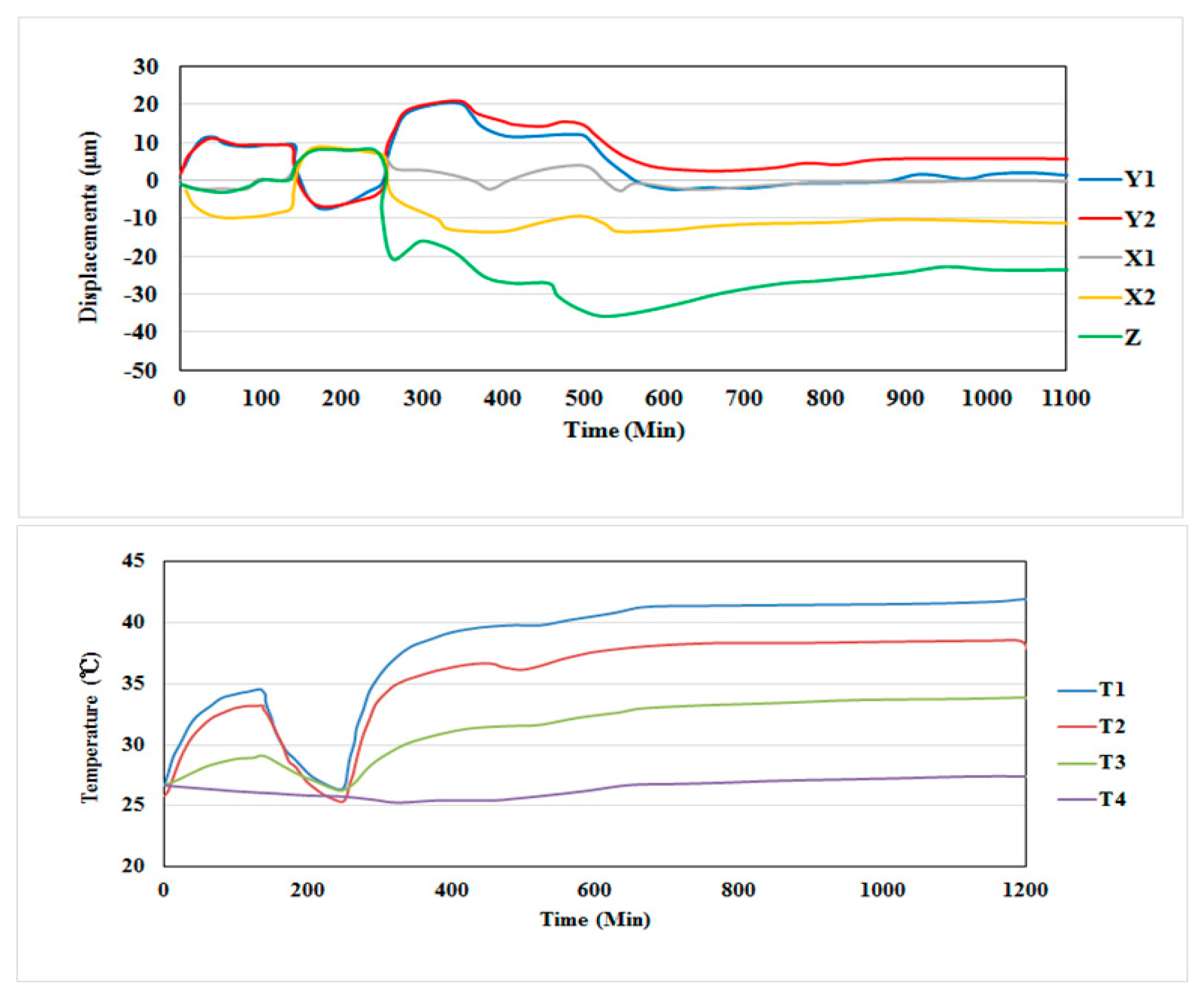
4.1. Displacement Variation without Compensation

Figure 11 shows the temperature and displacement variations of the working table on the x- and y-axes and the spindle nose on the z-axis during the 400 h operations. It is found that the x and y axial displacement variations are within the range of 10–25 µm and 8–20 µm, respectively. While the displacement variation on the z-axis is about 70 µm. The greater displacement variation on the z-axis can be ascribed to the fact that there is a high temperature rise in the spindle unit running at high speed for a long time. It can be expected that this will result in the poor precisions in machining.

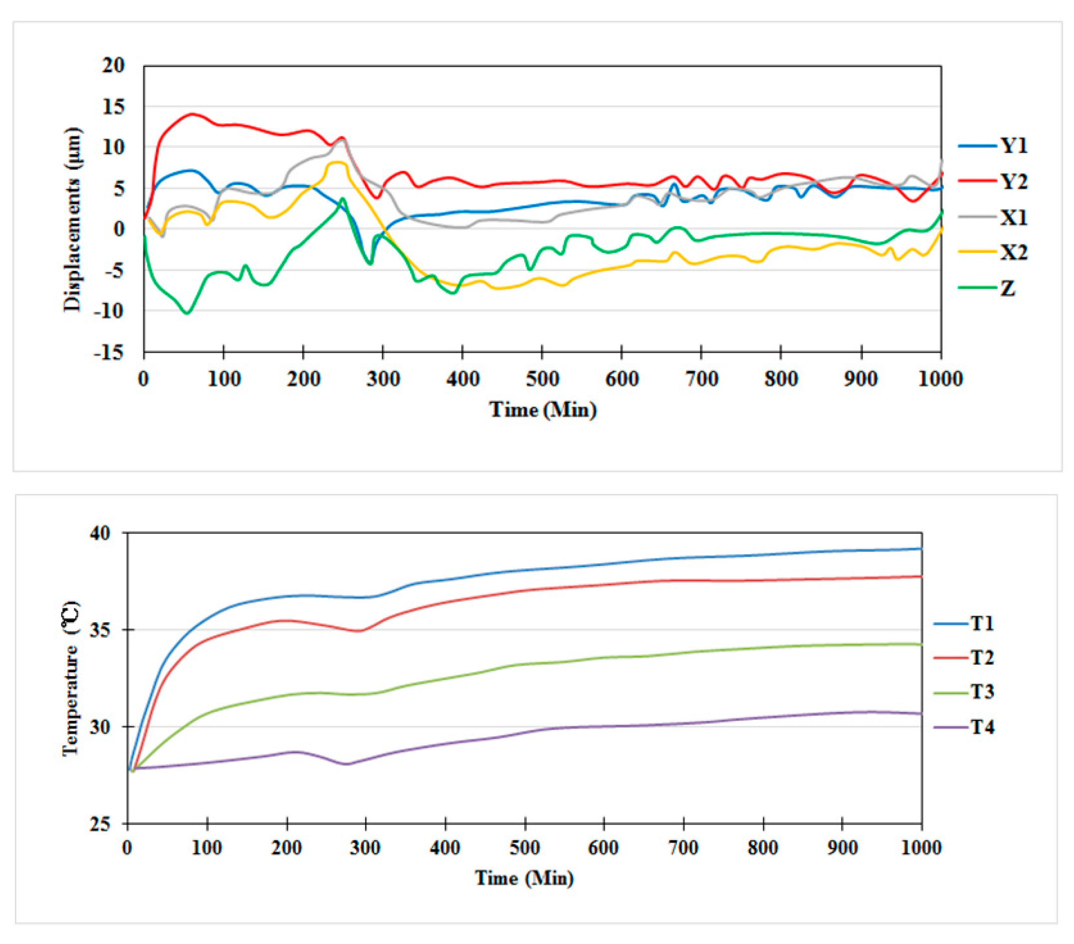
4.2. Displacement Variation with Compensation

Figure 12 shows the temperature and displacement variations on the x-, y-, and z-axes during the 400 h operations when activating the compensation modulus. In this case, we can find that the maximum displacement variations on the x- and y-axes are within 30 and 20 µm, respectively. While the displacement variation on the z-axis is about 40 µm. It is apparent that the displacement error on the z-axis was controlled within a small range by the compensation module.
Since the displacement variations on the y- and z-axes are still beyond the desired range, we adjusted the control parameters of compensation module and conducted the test again following the previous procedures. Figure 13 shows the temperature and displacement variations on the x-, y-, and z-axes during the 400 h operations when activating the modified compensation module. In this case, the maximum displacement variations on the x- and y-axes are controlled within 14–20 µm and 15–20 µm, respectively. While the displacement variation on the z-axis is also controlled below 20 µm approximately. This result again verifies the feasibility of the compensation module to reduce thermal error caused by the temperature rise of the spindle tooling system.

4.3. Machining Test

After several times testing of the compensation system, the displacement variations on the x- and y-axes was controlled to be less than 20 µm, and the displacement variation of the spindle tool center point (TCP) also was controlled within in 20 µm. Finally, we conducted the machining test to verify performance of the compensation system in machining applications. The workpiece material is aluminum with the size of 200 mm × 200 mm × 50 mm. The cutter is a three flute carbide ball end mill with radius of 3 mm and length of 120 mm. The machined parts are shown in Figure 14. A detailed visual examination reveals that the workpiece machined under the activation of the compensation system shows a finished surface, but there are some stripes on the workpiece machined without thermal compensation. The surface accuracy was further examined for workpieces under machining with and without the activation of the thermal compensation system. The surface accuracy of the machined parts without thermal compensation is −25 µm (minimum) and 21 µm (maximum). Figure 14b is machined parts under compensation and the surface accuracy is −14 µm (minimum) and 1 µm (maximum). The overall efficiency is increased by 33%. This result indeed demonstrates the feasibility of the compensation module for reducing the thermal errors in practical machining applications.

5. Conclusions

This study aimed to develop a compensation system for controlling the thermal induced positioning error of a CNC milling machine. The compensation system based on the data-driven thermal model was implemented on a milling machine and then verified through the machining test. According to the results, some conclusions can be drawn as follows:
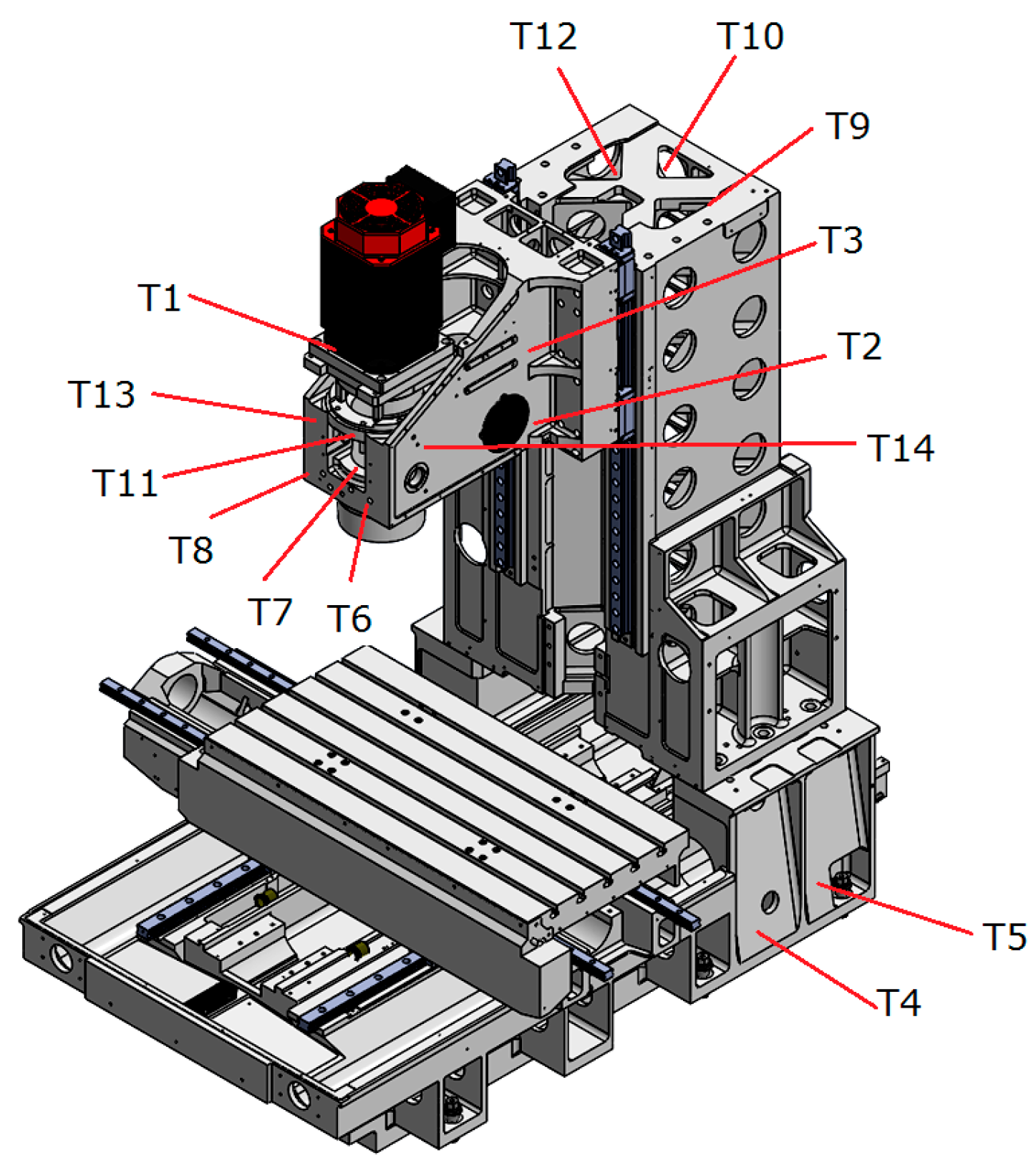
  • Selection of the locations for sensing the temperature fields of the machine tool is very important for establishing the correct thermal model. We first used 14 temperature sensors to examine the real temperature fields around the machine, from which the four major sensing points were selected.
  • Through the proposed thermal compensation system, the displacement variations on the x- and y-axes and the position error at the tool center can be controlled within 20 µm.
  • Application of the thermal compensation system in milling operation examinations of the machined surface reveal that the surface accuracy can be controlled within −14 µm (minimum) and 1 µm (maximum) under the activation of the compensation system. Compared with the machined surface without thermal compensation, the overall efficiency is increased by 33%. The feasibility of the compensation system was successfully demonstrated in application in the milling operation.
Finally, the proposed compensation system was developed for a three-axis milling machine. For application on four- or five-axis machine tools, the thermal model should be established following the proposed method. However, this would be a hard task since there are more heat sources in the rotary table and swivel head to be examined, which may cause the displacement errors of the rotational axis. This will be part of our future studies and experiments on multiple-axis machine tools.

Acknowledgments

The authors would like to acknowledge the support of Quaser Machine Tools Inc. The assistance with the experiment from the Precision Machinery Research & Development Center (PMC) in Taiwan is also highly appreciated.

Author Contributions

Tsung-Chia Chen contributed to the organization of the research work, including the experimental configuration, compensation module and manuscript preparation. Chia-Jung Chang and Jui-Pin Hung contributed to the experiment measurements and data analysis. Rong-Mao Lee and Cheng-Chi Wang conducted the experimental work of the machining systems.

Conflicts of Interest

The authors declare no conflict of interest.

References

  1. Bryan, J.B. International status of thermal error research. CIRP Ann. Manuf. Technol. 1990, 39, 645–656. [Google Scholar] [CrossRef]
  2. Ferrreira, P.M.; Liu, C.R. A method for estimating and compensating quasistatic errors of machine tools. Trans. ASME J. Eng. Ind. 1993, 115, 149–159. [Google Scholar] [CrossRef]
  3. Yanga, H.; Ni, J. Dynamic neural network modelling for nonlinear, nonstationary machine tool thermally induced error. Int. J. Mach. Tools Manuf. 2005, 45, 455–465. [Google Scholar] [CrossRef]
  4. Zhang, Y.M.; Liu, Q.W.; Han, J.L. Finite element analysis on thermal characteristic of the headstock of NC machine tool. Adv. Mater. Res. 2011, 291–294, 2302–2305. [Google Scholar] [CrossRef]
  5. Zhang, J.F.; Feng, P.F.; Wu, Z.J.; Yu, D.W.; Chen, C. Thermal structure design and analysis of a machine tool headstock. Mechanics 2013, 19, 478–485. [Google Scholar] [CrossRef]
  6. Donmez, M.A.; Hahn, M.H.; Soons, J.A. A novel cooling system to reduce thermally-induced errors of machine tools. CIRP Ann. Manuf. Technol. 2007, 56, 521–524. [Google Scholar] [CrossRef]
  7. Kishawy, H.A.; Dumitrescu, M.; Ng, E.G.; Elbestawi, M.A. Effect of coolant strategy on tool performance, chip morphology and surface quality during high-speed machining of A356 aluminum alloy. Int. J. Mach. Tools Manuf. 2005, 45, 219–227. [Google Scholar] [CrossRef]
  8. Kodera, T.; Yokoyama, K.; Miyaguchi, K.; Nagai, Y.; Suzuki, T.; Masuda, M.; Yazawa, T. Real-time estimation of ball-screw thermal elongation based upon temperature distribution of ball-screw. JSME Int. J. Ser. C Mech. Syst. 2004, 47, 1175–1181. [Google Scholar] [CrossRef]
  9. Kim, S.K.; Cho, D.W. Real-time estimation of temperature distribution in a ballscrew system. Int. J. Mach. Tools Manuf. 1997, 37, 451–464. [Google Scholar] [CrossRef]
  10. Yuan, J.; Ni, J. The real-time error compensation technique for CNC machining systems. Mechatronics 1998, 8, 359–380. [Google Scholar] [CrossRef]
  11. El Ouafi, A.; Guillot, M.; Barka, N. An integrated modeling approach for ANN-based real-time thermal error compensation on a CNC turning center. Adv. Mater. Res. 2013, 664, 907–915. [Google Scholar] [CrossRef]
  12. Yang, J.; Yuan, J.; Ni, J. Thermal error mode analysis and robust modeling for error compensation on a CNC turning center. Int. J. Mach. Tools Manuf. 1999, 39, 1367–1381. [Google Scholar] [CrossRef]
  13. Donmez, M.A.; Blomquist, D.S.; Hocken, R.J.; Liu, C.R.; Barash, M.M. A general methodology for machine tool accuracy enhancement by error compensation. Precis. Eng. 1986, 8, 187–196. [Google Scholar] [CrossRef]
  14. Chen, J.S.; Yuan, J.; Ni, J.; Wu, S.M. Real-time compensation for time-variant volumetric errors on a machining center. Trans. ASME J. Eng. Ind. 1993, 115, 472–479. [Google Scholar] [CrossRef]
  15. Lo, C.H.; Yuan, J.; Ni, J. An application of real-time error compensation on a turning center. Int. J. Mach. Tools Manuf. 1995, 35, 1669–1682. [Google Scholar] [CrossRef]
  16. Lee, D.S.; Choi, J.Y.; Choi, D.H. ICA based thermal source extraction and thermal distortion compensation method for a machine tool. Int. J. Mach. Tools Manuf. 2003, 43, 589–597. [Google Scholar] [CrossRef]
  17. Postlethwaite, S.R.; Allen, J.P.; Ford, D.G. The use of thermal imaging, temperature and distortion models for machine tool thermal error reduction. Proc. Inst. Mech. Eng. B J. Eng. Manuf. 1998, 212, 671–679. [Google Scholar] [CrossRef]
  18. Vanherck, P.; Dehaes, J.; Nuttin, M. Compensation of thermal deformation in machine tools with neural nets. Comput. Ind. 1997, 33, 119–125. [Google Scholar] [CrossRef]
  19. Lee, J.H.; Lee, J.H.; Yang, S.H. Thermal error modeling of a horizontal machining center usingfuzzy logic strategy. J. Manuf. Process. 2001, 3, 120–127. [Google Scholar] [CrossRef]
  20. Abdulshahed, A.M.; Longstaff, A.P.; Fletcher, S.; Myers, A. Application of GNNMCI(1, N) to environmental thermalerror modelling of CNC machine tools. In Proceedings of the 3rd International Conference on Advanced Manufacturing Engineering and Technologies, Stockholm, Sweden, 27–30 October 2013; pp. 253–262.
  21. Abdulshahed, A.M.; Longstaff, A.P.; Fletcher, S.; Myers, A. Comparative study of ANN and ANFIS prediction models for thermal error compensation on CNC machine tools. In Proceedings of the Laser Metrology and Machine Performance X: Lamdamap 10th International Conference, Buckinghamshire, UK, 20–21 March 2013; pp. 79–88.
  22. Abdulshahed, A.M.; Longstaff, A.P.; Fletcher, S. A novel approach for ANFIS modelling based on Grey system theory for thermal error compensation. In Proceedings of the 14th UK Workshop on Computational Intelligence (UKCI), Bradford, UK, 8–10 September 2014.
  23. Abdulshahed, A.M.; Longstaff, A.P.; Fletcher, S. A particle swarm optimisation-based Grey prediction model for thermal error compensation on CNC machine tools. In Proceedings of the Laser Metrology and Machine Performance XI: 11th International Conference and Exhibition on Laser Metrology, Machine Tool, CMM and Robotic Performance (Lamdamap), Huddersfield, UK, 17–18 March 2015.
  24. Horejš, O.; Mareš, M.; Novotný, L. Advanced modelling of thermally induced displacements and its implementation into standard CNC controller of horizontal milling center. Procedia CIRP 2012, 4, 67–72. [Google Scholar] [CrossRef]
  25. Chen, J.S.; Chiou, G. Quick testing and modeling of thermally-induced errors of CNC machine tools. Int. J. Mach. Tools Manuf. 1995, 35, 1063–1074. [Google Scholar] [CrossRef]
  26. Kurtoglu, A. The accuracy improvement of machine tools. Ann. CIRP 1990, 39, 417–419. [Google Scholar] [CrossRef]
  27. Hao, W.; Hongtao, Z.; Qianjian, G.; Xiushan, W.; Jianguo, Y. Thermal error optimization modeling and real-time compensation on a CNC turning center. J. Mater. Process. Technol. 2008, 207, 172–179. [Google Scholar] [CrossRef]
  28. Yang, S.; Yuan, J.; Ni, I. The improvement of thermal error modeling and compensation on machinetools by CMAC neural network. Int. J. Mach. Tools Manuf. 1996, 36, 527–537. [Google Scholar] [CrossRef]
  29. Vyroubal, J. Compensation of machine tool thermal deformation in spindle axis direction based on decomposition method. Precis. Eng. 2012, 36, 121–127. [Google Scholar] [CrossRef]
  30. Abdulshahed, A.M.; Longstaff, A.P.; Fletcher, S.; Myers, A. The application of ANFIS prediction models for thermal error compensation on CNC machine tools. Appl. Soft Comput. 2015, 27, 158–168. [Google Scholar] [CrossRef]
  31. Abdulshahed, A.M.; Longstaff, A.P.; Fletcher, S.; Myers, A. Thermal error modelling of machine tools based on ANFIS with fuzzy c-means clustering using a thermal imaging camera. Appl. Math. Model. 2015, 39, 1837–1852. [Google Scholar] [CrossRef]
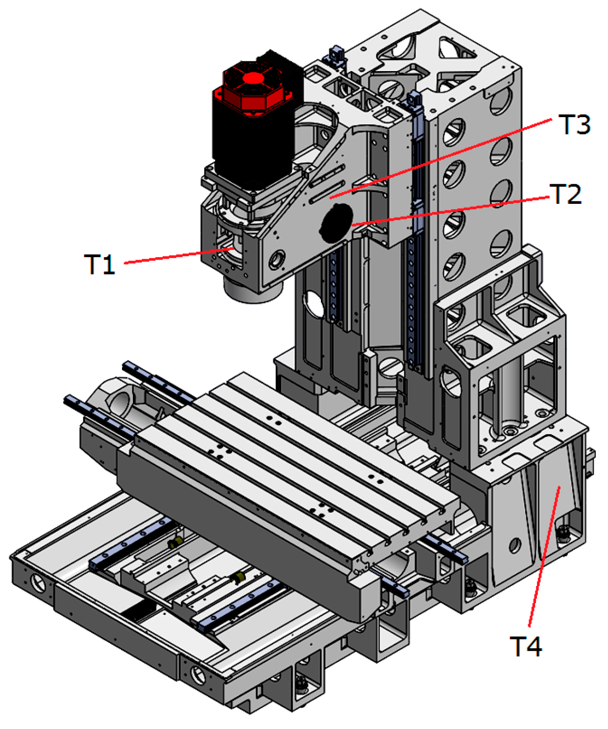
Figure 1. Thermal deformation of machine tools.
Applsci 06 00101 g001
Figure 2. Factors inducing thermal deformations.
Applsci 06 00101 g002
Figure 3. MV204C Quaser machine tools.
Applsci 06 00101 g003
Figure 4. Schematics of the initial measurement of temperature fields with 14 sensors.
Applsci 06 00101 g004
Figure 5. Initial temperature rises measured at 14 sensors.
Applsci 06 00101 g005
Figure 6. Schematics of the locations of temperature sensors.
Applsci 06 00101 g006
Figure 7. Measurement of displacements of working table in X, Y and Z directions.
Applsci 06 00101 g007
Figure 8. Temperature rises with time measured at four sensors.
Applsci 06 00101 g008
Figure 9. Thermal compensation module.
Applsci 06 00101 g009
Figure 10. Communication module.
Applsci 06 00101 g010
Figure 11. Temperature and displacement variations of the working table on the x- and y-axes and the spindle nose on the z-axis during the 400 h operations.
Applsci 06 00101 g011
Figure 12. Temperature and displacement variations on the x-, y-, and z-axes under the activation of temperature compensation system.
Applsci 06 00101 g012
Figure 13. Temperature and displacement variations on the x-, y-, and z-axes controlled by the modified compensation system.
Applsci 06 00101 g013
Figure 14. Machined surface (a) without compensation (b) with compensation.
Applsci 06 00101 g014
Table 1. Locations of the temperature sensors.
Temperature SensorLocations
T1Nearby rear bearings of spindle
T2Heat source of belt transmission in spindle head
T3Nearby spindle motor (directly)
T4Machine base, temperature of the environment

