1. Introduction
As computer performance has increased, simulations that replicate an actual system are used in various industrial fields, including the marine industry, to evaluate the dynamic characteristics of a product prior to its fabrication. Such technology is known as computer-aided engineering (CAE). Utilization of such technology in actual production sites has advantages in terms of cost savings and a shorter development period. Recent studies: compensator was designed by Hatlestkog that uses 2 gas DSC cylinders, which was studied through numerical analysis to confirm damping factor [
1]. Sol Ha simulated ship and process in ship yard using multi body dynamcis analysis [
2]. Peter Gu optimized AHC system of hoisting rig using the dynamics analysis [
3]. Qingyou Liu verified mechanical semi active compensation system using oil pressure analysis [
4]. Same as the researches applied through computer simulation, have various forms in the design step, because offshore plant cost a lot in development.
Because of the complexity of parts organization, analysis technology and software for multi-body dynamics are used for system analysis, allowing the identification of design errors. This is done by determining the behaviors of parts resulting from the load or deformation, not inside a part, but generated by its movement and transferred to other parts, and by assessing interference between parts. Compared with previous manual parametric modeling, multi-body dynamics analysis technology, when used with an existing compatible design program, facilitates modeling and analysis of complicated machine systems [
5,
6,
7,
8,
9]. This technology works by dividing the components of the machine system into body, joint, and force elements, and by applying the mechanical and dynamic constraints distinctive to each component to organize the system equation of motion.
In this study, when the compensation system for an offshore plant is designed, a 1:5 scale compensator was manufactured and tested for vibration. After the oil pressure system was modeled, the proper AHC control value was known through simulation. DSC and AHC cylinder speed were detected through multi body dynamics analysis. Therefore, results were expected to get correct design value through various researches and to economize the manufacturing cost and time.
A heave compensation system comprises a drill string compensator (DSC) and an active heave compensator (AHC). The DSC reduces the disturbance caused by the heave motion of the platform applied to the heavy object suspended from the hosting system, and attenuates disturbance by up to ~90%. The AHC is added to the DSC, and thus reduces disturbance of heave motion by ~5% and applies control force to the part supporting the heavy object. It can also attenuate the disturbance of heave motion by applying control force in a positive or negative direction. In general, an oil pressure system is used to apply the control force [
10].
Unlike drilling work carried out on the ground, in drilling work carried out in the marine environment, the key is to minimize the influence of the external force of fluid applied to the hull. Accordingly, in this study, a dynamics analysis model and a structural analysis model are proposed to determine dynamic performance and safety for the design of a heave compensator system for marine plants.
2. Analysis Modeling
2.1. Heave Compensation System Oil Pressure Modeling
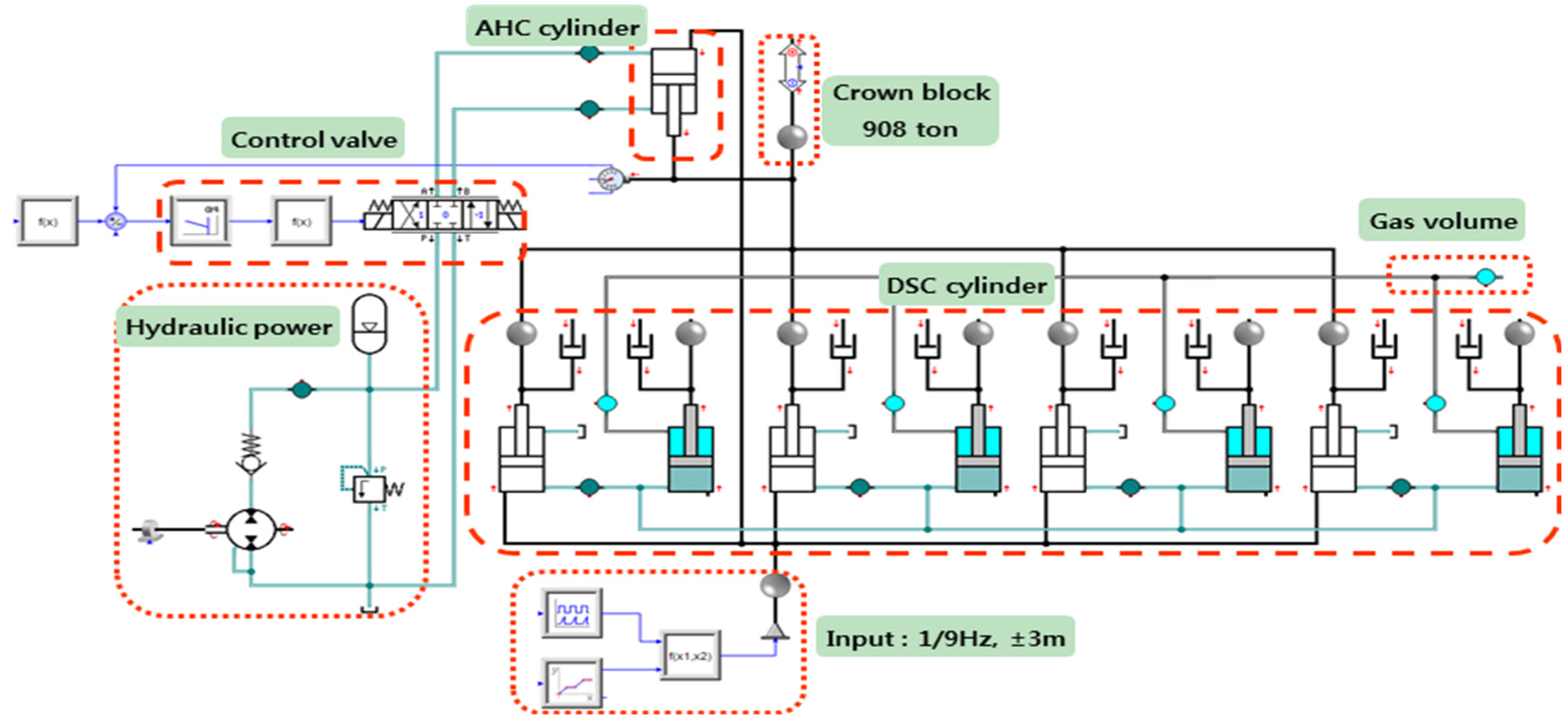
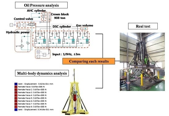
The analysis model for the oil pressure model to be developed in this study is shown in
Figure 1. It is built by combining an AHC system with four DSC cylinders and a piston accumulator. The AHC system is built as a proportional integral and derivative (PID) control system with feedback from displacement. The AHC system has a structure moving in the direction opposite the DSC cylinders, which attenuates vibration of the crown block. Throttle valves (Th1 and Th2) are used to remove the pressure of the AHC cylinder when the initial position of the DSC system is set, and are closed to control the pressure inside the AHC cylinder when the system operates normally.
Figure 1.
Simulation model of heave compensation system.
Figure 1.
Simulation model of heave compensation system.
2.2. Test Using a Test Rig
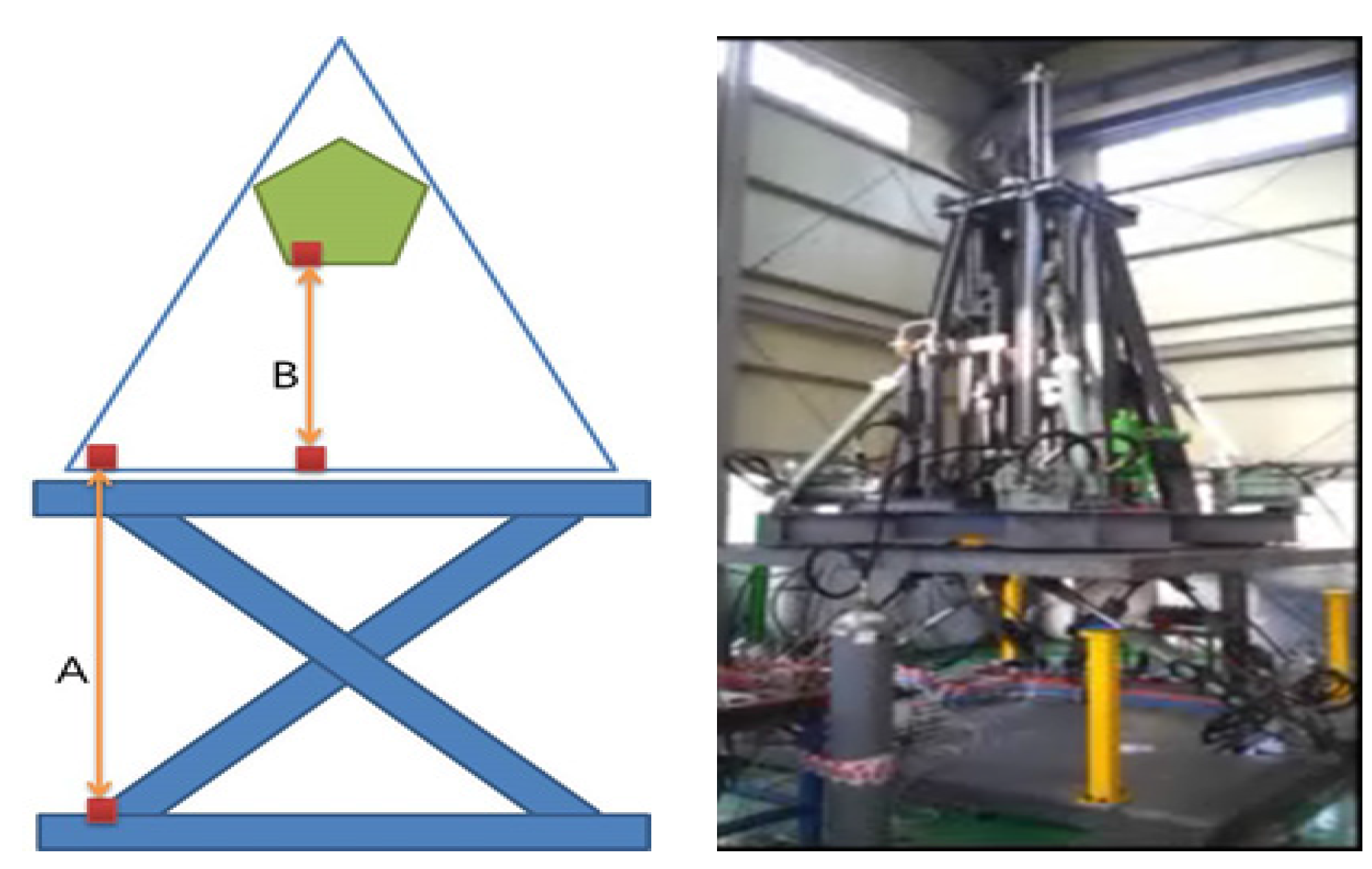
A test was conducted using a test rig and the results correlated with those of the analysis model for verification. The excitation input of the test rig (A) and the displacement of the crown block (B) were measured using a non-contact laser displacement sensor as shown in
Figure 2. The zero condition was set to compare the displacement measurement data of the test rig and the crown block, and post-processing of the measurement data was conducted to analyze the correlation between the displacement input into the test rig and the displacement output of the crown block. Furthermore, as there was much noise in the measurement data, it was filtered to the extent that the measurement signal was not affected.
Figure 2.
Schematic of displacement measurement in the test rig.
Figure 2.
Schematic of displacement measurement in the test rig.
2.3. Multi-Body Dynamics Modeling
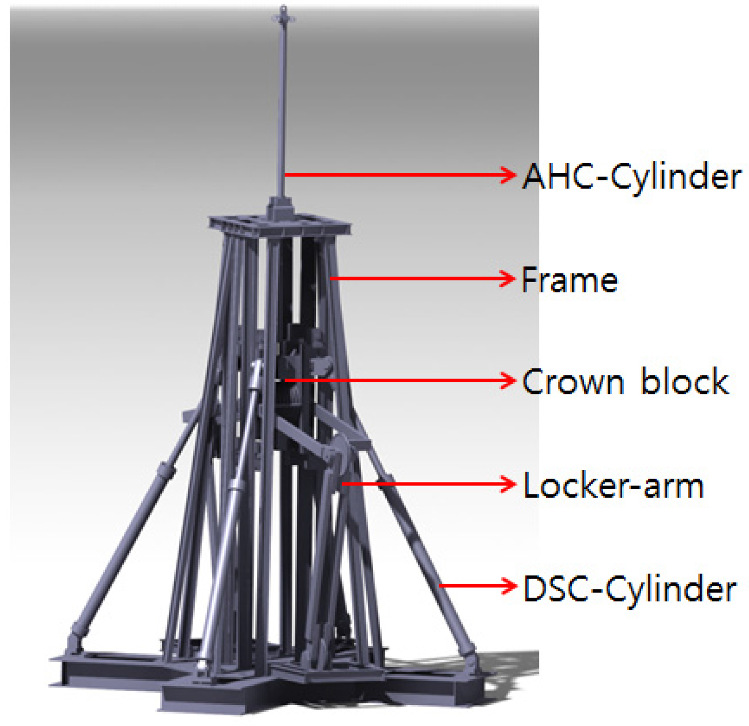
Figure 3 shows the heave compensator model used, which was generated using CATIA v5 (Paris, France), a three-dimensional modeler. The heave compensator is located at the top of the derrick, and fixed to the bottom of the frame. The four DSC cylinders, which reduce the heave motion at the lower part, are connected to the crown block and are slanted relative to the frame. The AHC cylinder connected to the top of the crown block is designed to control the heave motion and is fixed to the frame.
Figure 3.
Three-dimensional model of the heave compensator.
Figure 3.
Three-dimensional model of the heave compensator.
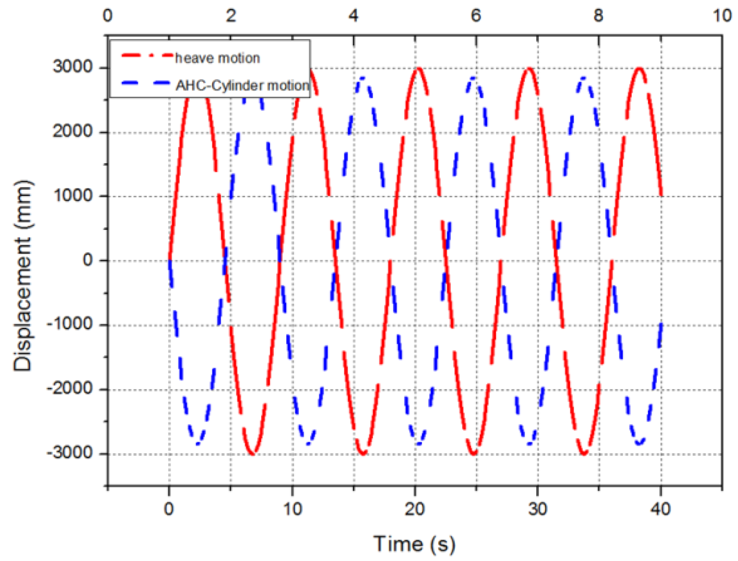
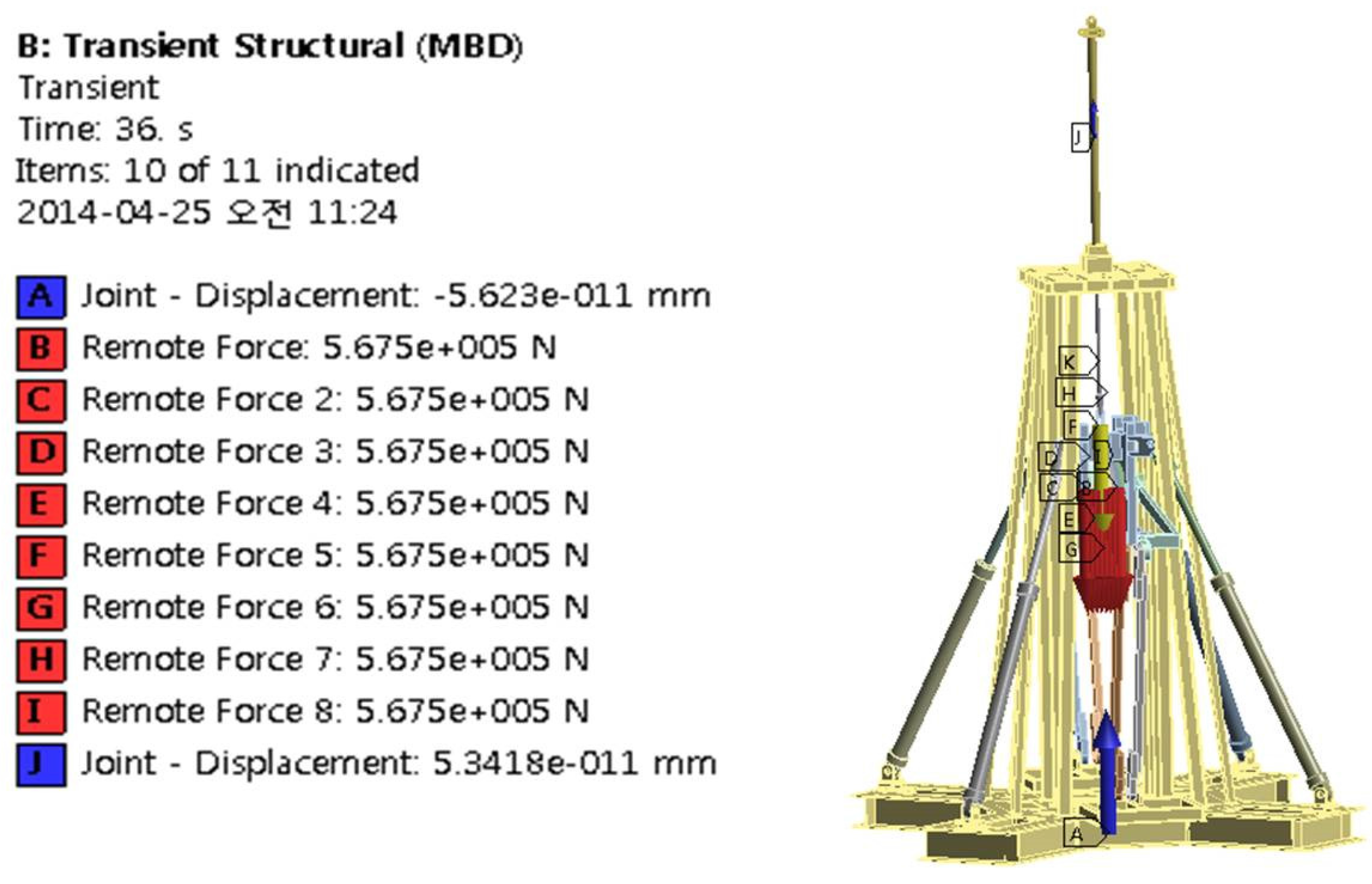
Figure 4 shows the boundary condition from ANSYS Workbench v. 12 (Canonsburg, PA, USA) for multi-body dynamics (MBD) analysis. An MBD analysis of the heave compensator was carried out. A sine wave with 3000 mm amplitude and a cycle of 9 s was applied to the frame connected to the derrick to take into account the flow of the external fluid transferred to the hull, and a sine wave of 2850 mm amplitude with a 9 s cycle was applied in reverse waveform to take into account the control force of the AHC cylinder over such heave motion.
Figure 5 shows the boundary condition of multi-body dynamics. The heave motion of
Figure 4 has been applied to Frame, which is symbolic of “A”. The application load is 908 t what is drill pipe mass and drill bit mass. This load was applied on sheave face of crown block, respectively. Then this condition was expressed in “B” to “I”. “J” is AHC cylinder motion. This motion is the sine wave used for the analysis. For the sine wave amplitude of the AHC cylinder, the attenuation rate of 95% to 96% indicated by the oil pressure analysis and the test was taken into account. A live load of 908 t was applied to the sheave of the crown block, and its own weight was taken into account.
Figure 4.
Motion of heave and the AHC cylinder.
Figure 4.
Motion of heave and the AHC cylinder.
Figure 5.
Boundary condition of multi-body dynamics.
Figure 5.
Boundary condition of multi-body dynamics.
3. Results and Discussion
3.1. Oil Pressure Simulation Result
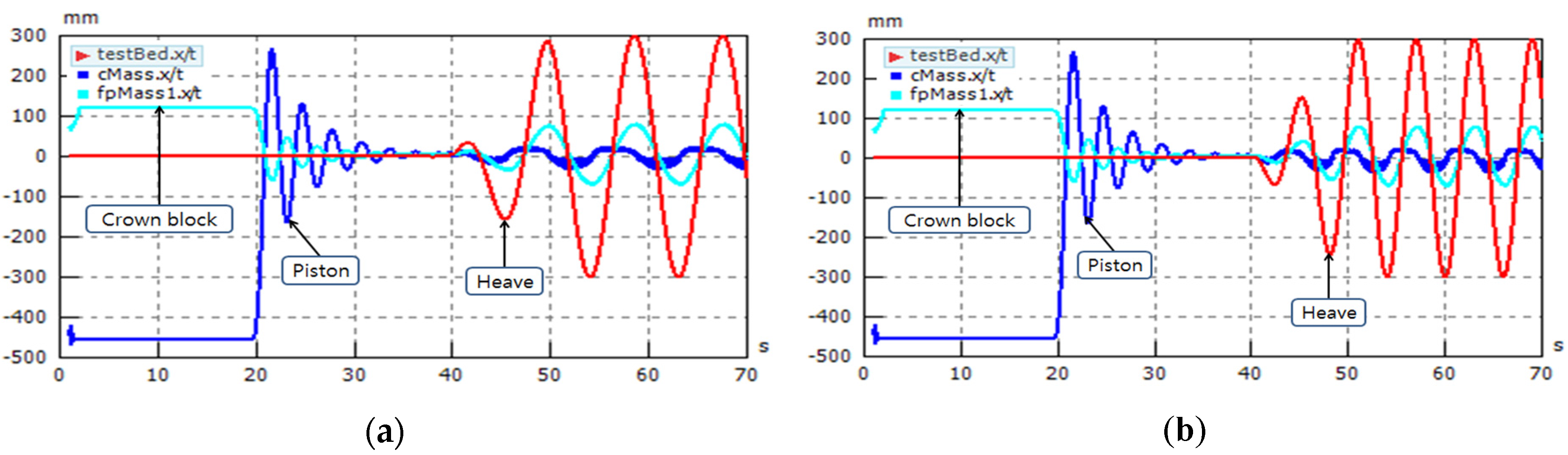
Figure 6 shows the result of an analysis scenario for a model constructed by mixing AHC and DSC. The analysis scenario was implemented using the concept of system installation.
Figure 6.
Results of oil pressure analysis, (a) ±0.3 m (1/9) Hz; (b) ±0.3 m (1/6) Hz.
Figure 6.
Results of oil pressure analysis, (a) ±0.3 m (1/9) Hz; (b) ±0.3 m (1/6) Hz.
For the heave, viz. the displacement excitation input, with the DSC system set to neutral, the vibration attenuation characteristics of the crown block were analyzed through PID control of the AHC system. When the DSC cylinders and piston accumulator reach the neutral position, excitation starts.
Using the AHC and DSC mixed model, the performance was analyzed by grasping the displacement attenuation characteristics of the crown block for the test bed input. Good performance is achieved when the change in the displacement of the DSC cylinder is reduced by the PID control of the AHC system.
In
Figure 6a,b, it can be seen that the dead band of the servo valve is 20%, with the valve vibrating at a high frequency for control. An optimal servo valve is required to fit the control specification of the AHC. If the capacity of the servo valve is relatively large, the degree of control drops, and, if the dead band scope is wide, the controllability deteriorates. The valve should be selected to fit the capacity of the AHC considering the target performance. Thus the DSC system, AHC system and the controller must satisfy the target performance.
3.2. Result of the Test Conducted Using the Test Rig
The excitation input condition of the 1/5 scale analysis model was set to be identical to the test condition to compare it with the test result.
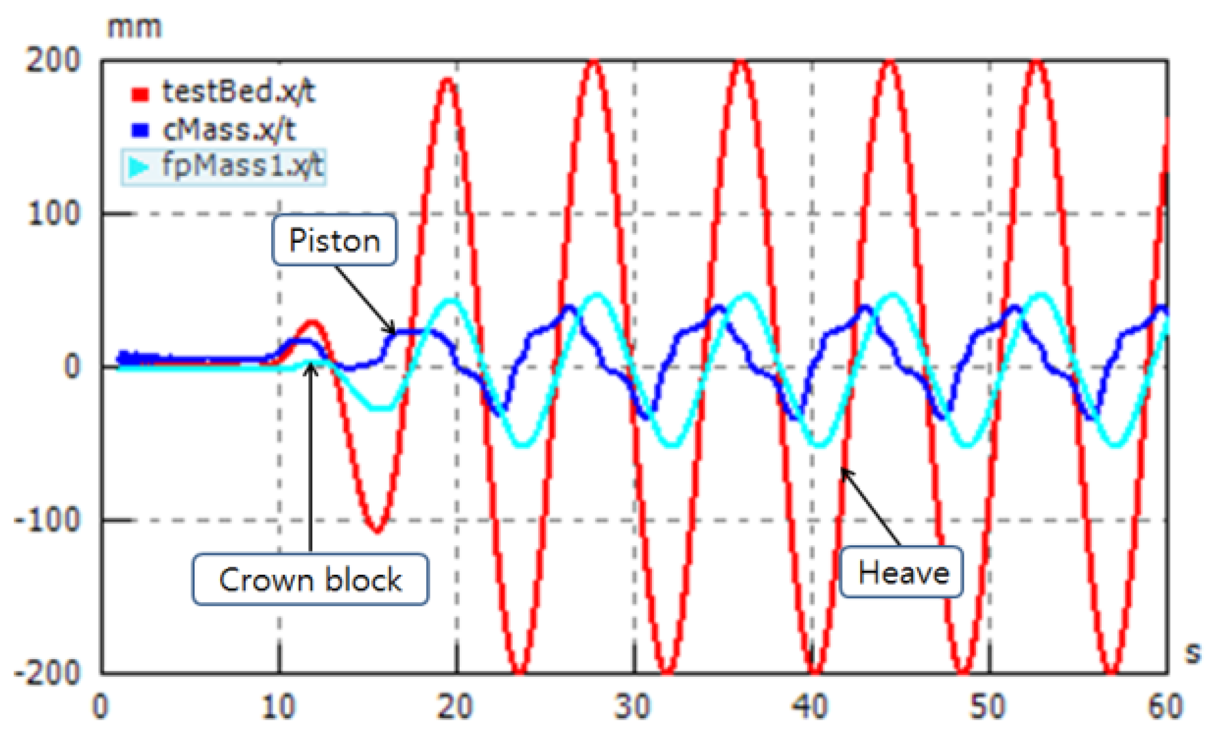
Figure 7 shows the excitation displacement input condition of ±150 mm,
v = 0.1 m/s (0.106 Hz).
Figure 8 shows the basic characteristics of the analysis model, and confirms that the displacement of the crown block is attenuated from the excitation pressure (heave) due to control by the DSC and AHC cylinders. The displacement of the accumulator (piston), resulting from the movement of the DSC cylinders moving in the direction the displacement of the crown block, can be reduced to attenuate the excitation input.
Figure 7.
Excitation displacement input condition.
Figure 7.
Excitation displacement input condition.
Figure 8.
Basic characteristics of the analysis model.
Figure 8.
Basic characteristics of the analysis model.
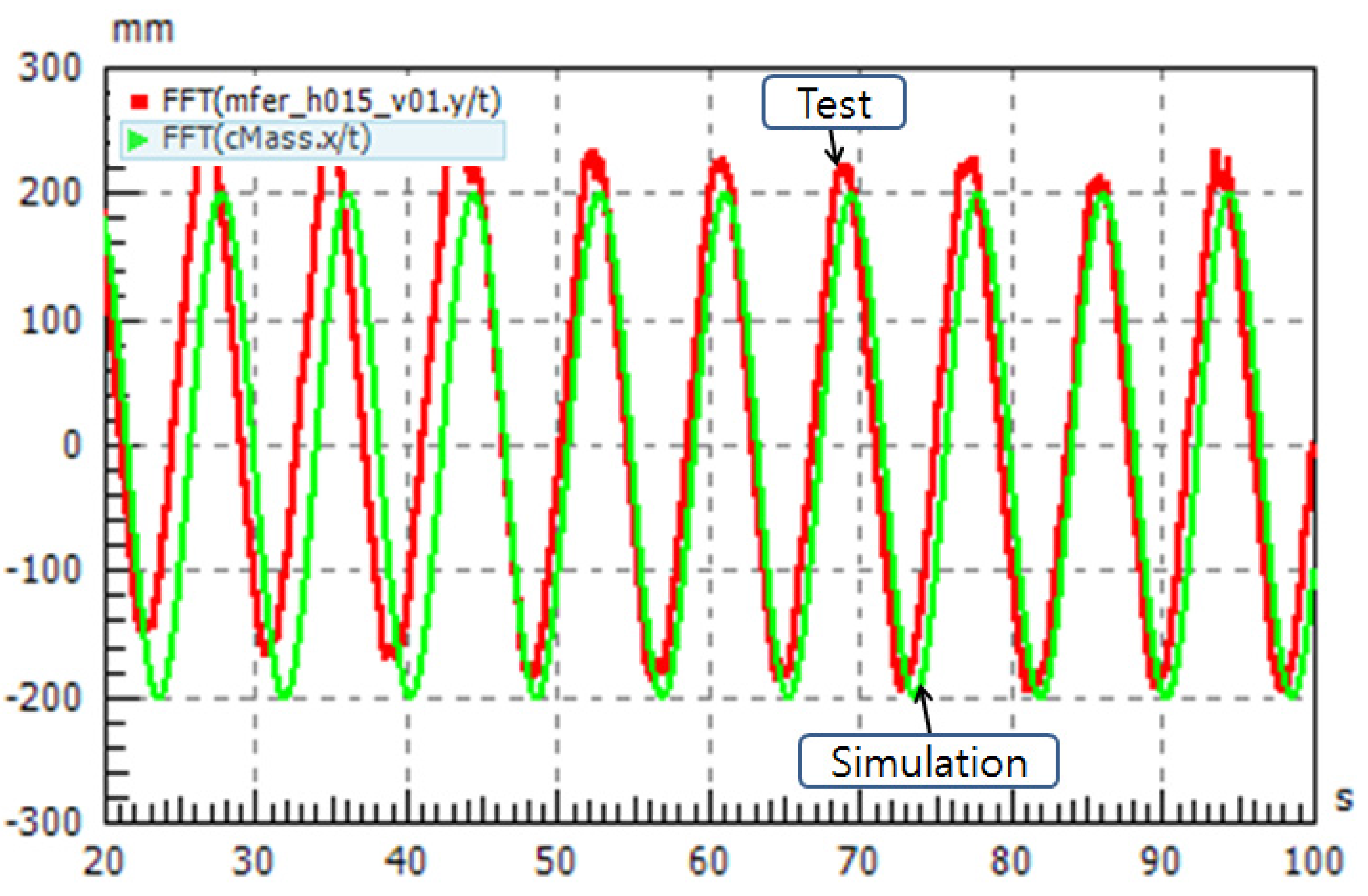
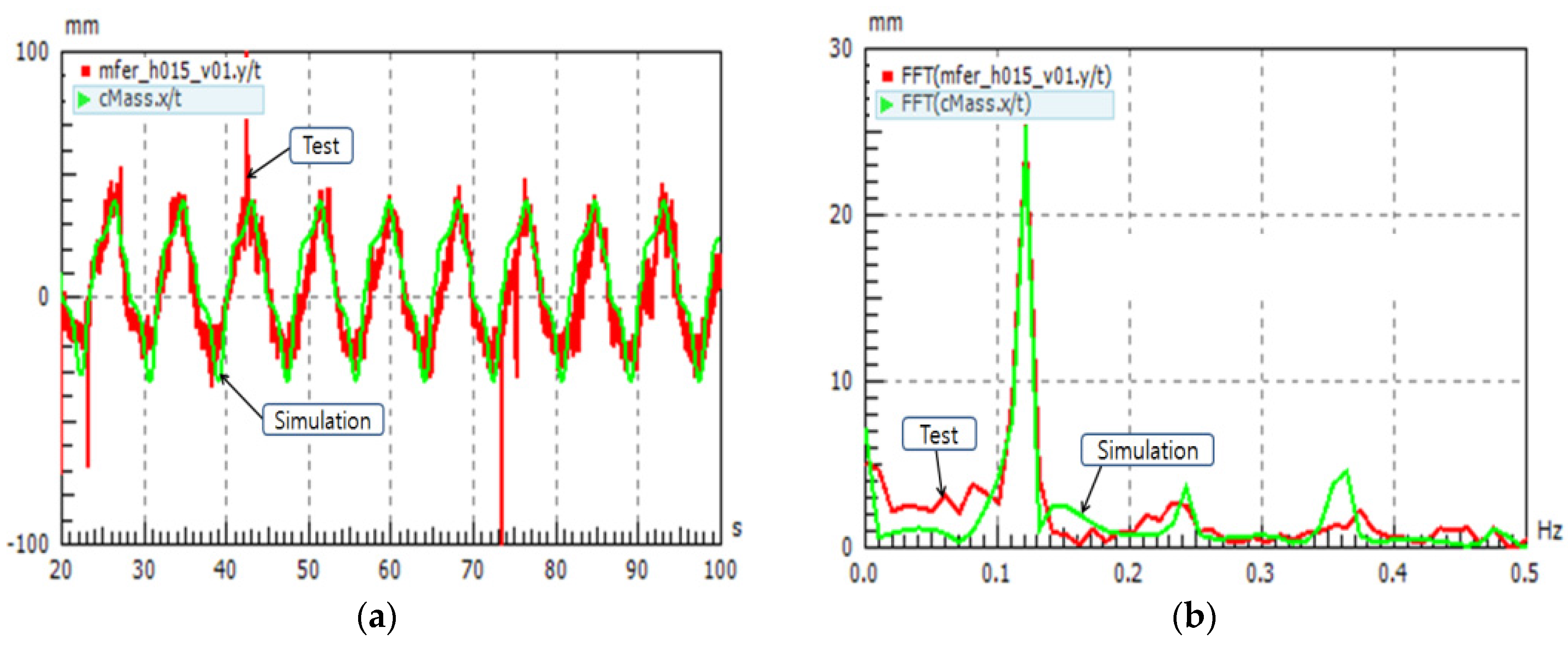
Figure 9 shows a comparison of the test and analysis results, which showed good agreement. The time data in (a) and the frequency characteristics in (b) show a good correspondence.
Figure 9 confirms that the analysis model is reliable.
Figure 9.
Comparison of test result and simulation result, (a) time data; (b) frequency characteristics.
Figure 9.
Comparison of test result and simulation result, (a) time data; (b) frequency characteristics.
3.3. Result of Multi-Body Dynamics Analysis
The coordinate system of six degrees of freedom (DOF) of a structure is defined as movements in three axial directions—movement in a vertical direction (heave), movement in the direction in which the wave progresses (surge), and movement perpendicular to the heave axis and the surge axis (sway). Yaw, roll and pitch are rotations around the heave, surge and sway axes, respectively.
Among these, those most important for a heave compensator are heave, roll and pitch. In this study, the behavioral characteristics of a heave compensator for heave motion were investigated.
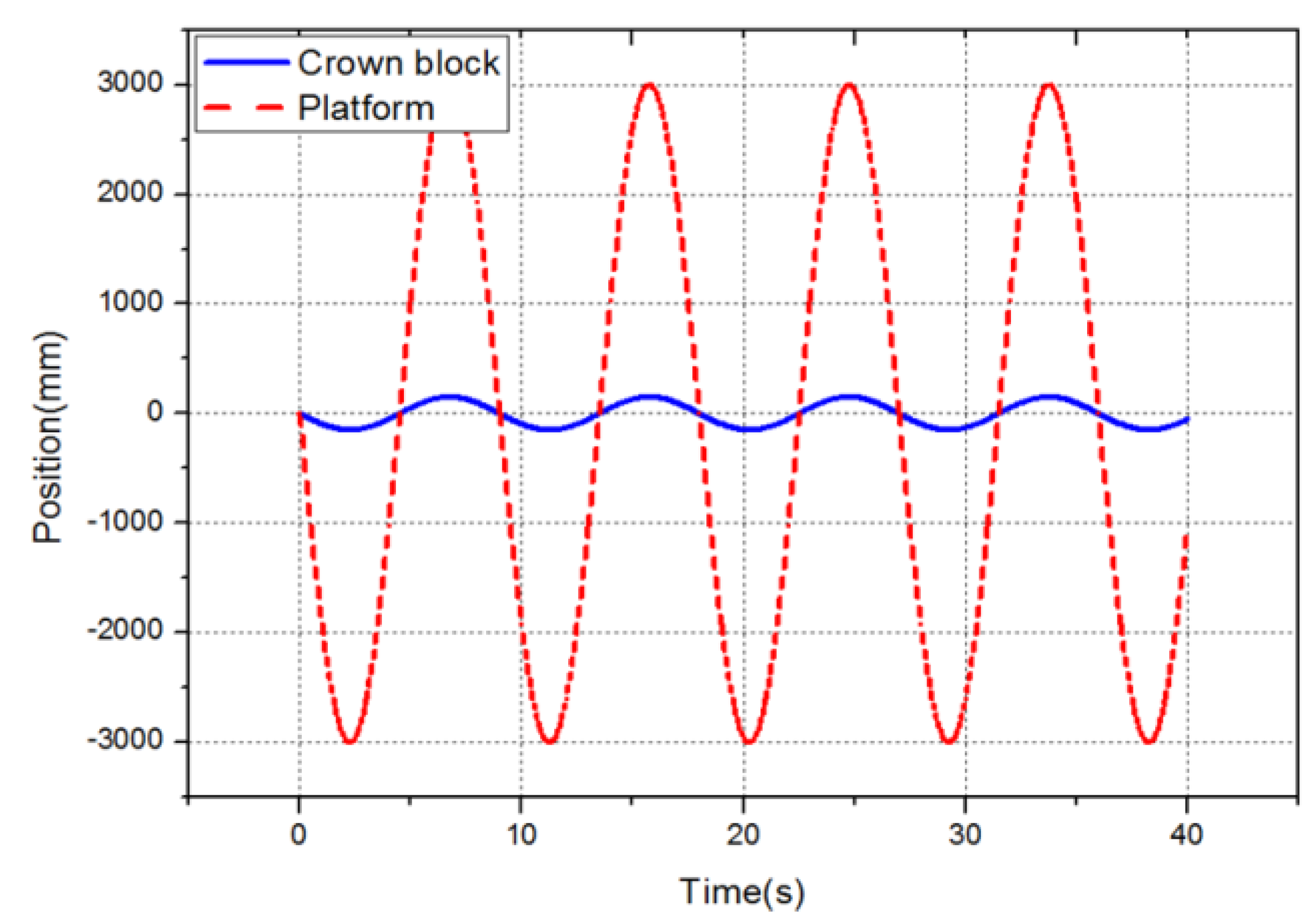
Figure 10 shows the result of displacements from the initial locations of the crown block and the frame obtained through MBD analysis.
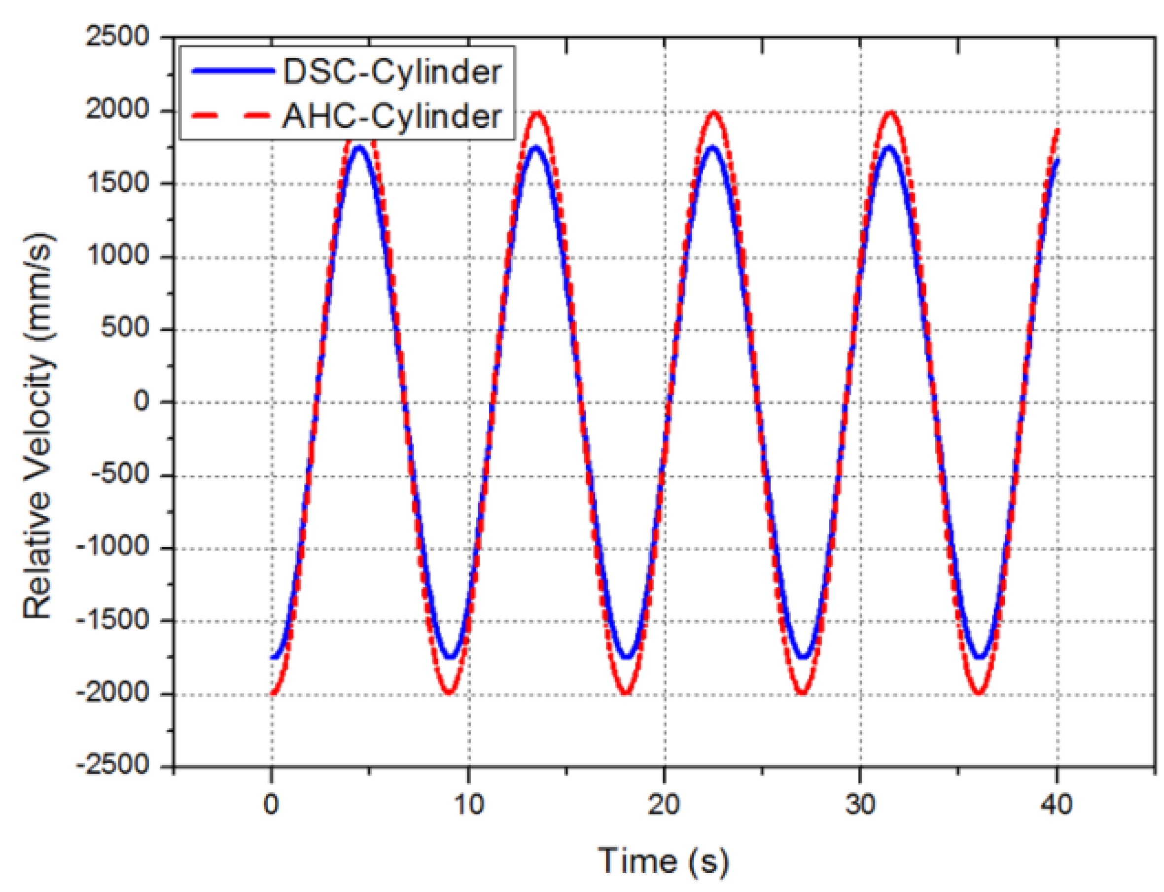
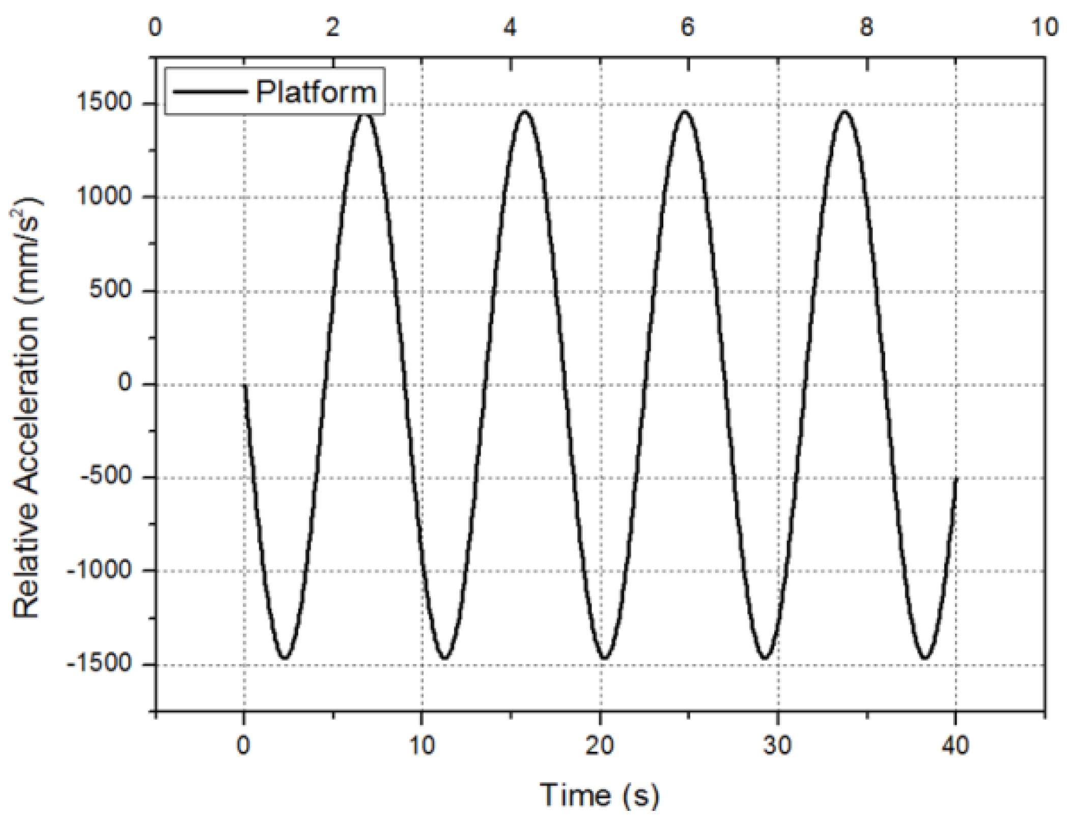
Figure 11 shows the speeds of the DSC cylinder and the AHC cylinder according to time band. When the compensation rate for a movement of ±3000 mm was 95%, the maximum speeds of the DSC cylinder and the AHC cylinder were 1.750 and 1.989 m/s, respectively. In addition, in
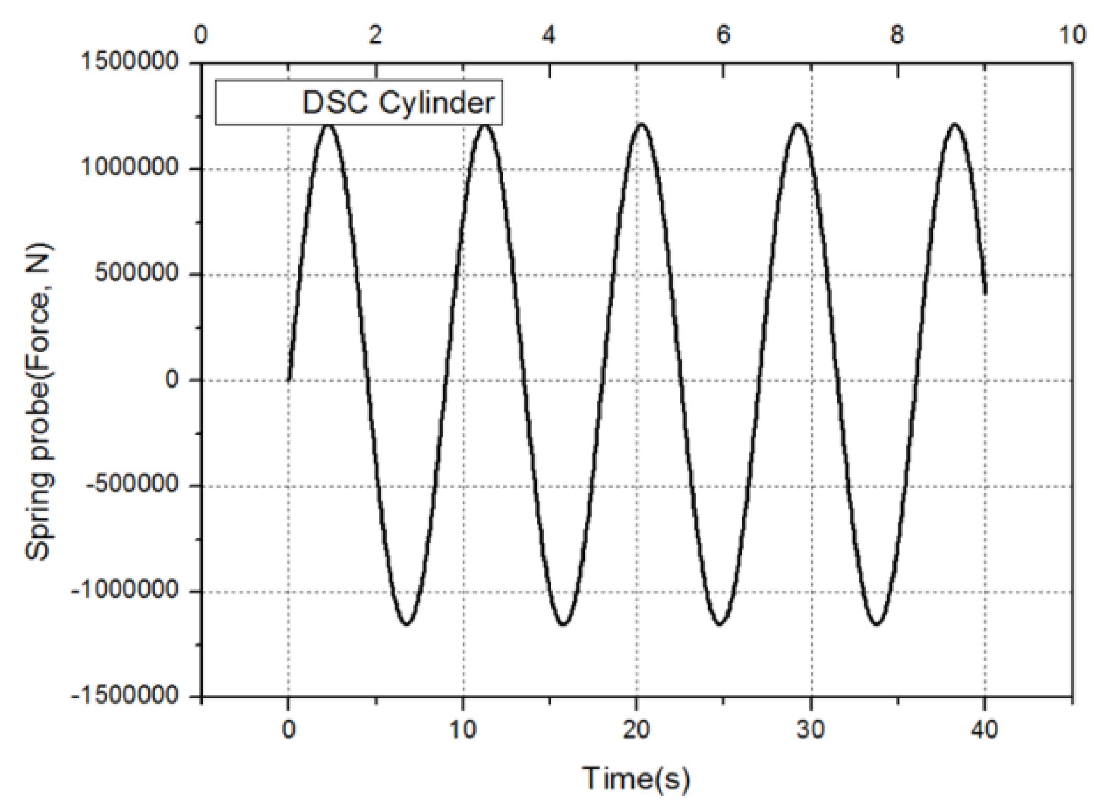
Figure 12 and
Figure 13, the maximum load of the DSC cylinder and a heave acceleration of 1.480 m/s
2 were obtained. This result can be used for structural analysis to determine the safety of a structure.
Figure 10.
Position of the crown block and frame.
Figure 10.
Position of the crown block and frame.
Figure 11.
Velocity of the AHC and DSC cylinder.
Figure 11.
Velocity of the AHC and DSC cylinder.
Figure 12.
Load of the DSC cylinder.
Figure 12.
Load of the DSC cylinder.
Figure 13.
Acceleration of heave.
Figure 13.
Acceleration of heave.
4. Conclusions
A model analysis was conducted by evaluating the functions and characteristics of each part to build a reliable analysis model for a heave compensator oil pressure system.
(1) During the component modeling, analysis models were developed based on the specifications in the drawings and the catalog of each part. They were confirmed using the design tool concept by predicting the validity and problems of design specifications in advance through computer simulations, and then fabricating them and using the results to change designs, solve problems, and formulate improvement plans.
(2) Upon comparison of the oil pressure system analysis and test results, it can be seen that the time data values correspond to the frequency characteristics, confirming the reliability of the analysis model. Moreover, the attenuation rate of 95% obtained through the analysis and test can be used as the basis for determining the dynamic behavioral characteristics of the compensator structure.
(3) The speeds of the AHC cylinder and the DSC cylinder were confirmed through MOD analysis with attenuation at 95%. The design speed of the 1/5 size cylinder model was 1.5 m/s. The AHC cylinder speed of 1.989 m/s and the DSC cylinder speed of 1.750 m/s obtained by dynamics analysis were confirmed, and can be utilized in the design of an actual-size cylinder.
Acknowledgments
This research was supported by the Basic Science Research Program through the National Research Foundation of Korea (NRF) funded by the Ministry of Science (No. 2015R1A2A2A01004579) and was supported by the Gyeongsang National University fund for Professors on Sabbatical Leave, 2014.
Author Contributions
Drafting of manuscript: Gwi-Nam Kim and Sung-Gu Hwang; acquisition of oil pressure data: Jang-Hwan Hyeon and Young-Hwan Yoon and Yong-Gil Jung; Model; Analysis of hydraulic pressure: Young-Hwan Yoon; Analysis of multi-body dynamics: Gwi-Nam Kim and Sung-Gu Hwang; Planning and supervision of the research: Sun-Chul Huh.
Conflicts of Interest
The authors declare no conflict of interest.
References
- Hatleskong, J.T.; Dunnigan, M.W. Passive Compensator Load Variation for Deep-Water Drilling. IEEE J. Ocean. Eng 2007, 3, 593–602. [Google Scholar] [CrossRef]
- Ha, S.; Ku, N.K.; Roh, M.I.; Hwang, H.-J. Multibody system dynamics simulator for process simulation of ships and offshore plants in shipyards. Adv. Eng. Softw. 2015, 85, 12–25. [Google Scholar] [CrossRef]
- Gu, P.; Walid, A.A.; Iskandarani, Y.; Karimi, H.R. Modeling, simulation and design optimization of a hoisting rig active heave compensation system. Int. J. Mach. Learn. Cybern 2013, 4, 85–98. [Google Scholar] [CrossRef]
- Liu, Q.; Tang, Y.; Huang, C.; Xie, C. Study on a mechanical semi-active heave compensation sytem of drill string for use on floating drilling platform. PLoS ONE 2015, 10. [Google Scholar] [CrossRef]
- Jorgen, H.; Steffen, V.; Ilya, T.; Martin, C.; Geir, H.; Michael, R.H. The Effect of Friction in Passive and Active Heave Compensation of Crown Block Mounted Compensators. In Proceedings of the 2012 IFAC Workshop on Automatic Control in Offshore Oil and Gas Production, Norwegian University of Science and Technology, Trondheim, Norway, 31 May–1 June 2012; pp. 316–320.
- Liu, S.J.; Li, L.J. Control Performance Simulation on Heave Compensation System of Deep-Sea Mining Based on Dynamic Vibration Absorber. In Proceedings of the International Conference on Digital Manufacturing and Automation, Changsha, China, 18–20 December 2010; pp. 441–445.
- Ku, N.K.; Ha, S.; Roh, M.I. Study on the Applicability of a New Multi-Body Dynamics Program Through the Application to the Heave Compensation System. J. Comput. Struct. Eng 2013, 4, 247–254. [Google Scholar] [CrossRef]
- Lee, Y.B.; Ko, J.M.; Park, J.H. Study of the Cushion Characteristics in accordance with Shapes of Cushion Ring of Hydraulic Cylinder. Trans. Korea Fluid Power Syst. Soc. 2008, 5, 14–19. [Google Scholar]
- Lee, Y.B.; Yoon, Y.H. Modeling & Simulation of the Hydraulic Servo Actuator Cushion for Power Plant. J. KSTLE 2013, 29, 7–12. [Google Scholar]
- Dyer, I.; Taylor, R.E.; Newman, J.N.; Price, W.G. Sea Loads on Ships and Offshore Structure; Cambridge University Press: Cambridge, UK, 1990; pp. 147–222. [Google Scholar]
© 2016 by the authors; licensee MDPI, Basel, Switzerland. This article is an open access article distributed under the terms and conditions of the Creative Commons by Attribution (CC-BY) license (http://creativecommons.org/licenses/by/4.0/).

 ,
, 