Article

Structural Performance of Steel Pile Caps Strengthened with Perfobond Shear Connectors under Lateral Loading

1
Institute of R&D, Ji Seung Consultant Co., Ltd., Seoul 06128, Korea
2
Korea Institute of Civil Engineering and Building Technology, Goyang 10223, Korea
3
Hyundai Engineering Co. Ltd., Seoul 03058, Korea
4
Department of Architectural Engineering, Kyung Hee University, Yongin 17104, Korea
*
Author to whom correspondence should be addressed.
Appl. Sci. 2016, 6(11), 317; https://doi.org/10.3390/app6110317
Submission received: 7 September 2016 / Revised: 12 October 2016 / Accepted: 19 October 2016 / Published: 26 October 2016

Abstract

:
The conventional strengthening strategy on the connection between the steel pile cap and reinforced concrete footing requires a series of complicated processes such as the distribution of reinforcing bars, their anchorage into concrete, and the usage of shear keys. This study investigates the structural performance of steel pile caps strengthened with newly proposed perfobond shear connectors subjected to lateral loading. Test parameters include the type of perfobond shear connectors, infilled concrete depth, and the number of L-shaped steel plates. The applied load versus deformation curve is plotted for all specimens, and their failure modes are identified. The effects of the test parameters on the peak load are examined in this work. From the results of this study, it can be confirmed that the proposed perfobond shear connector can be utilized as an alternative to the conventional steel pile cap strengthening method using steel rebars.

1. Introduction

In case the reinforced concrete footing does not have enough bearing capacity to support various types of loads transmitted from the upper structure, steel pipe piles can be used to provide additional bearing capacity to the foundation. In order to guarantee the safe load transfer from the upper structure to the supporting layer of rocks, it is highly important to integrate the steel piles into the concrete footing slab. This can generally be achieved by the use of steel reinforcing bars (rebars) embedded into the concrete footing. However, it is not easy to retain a sufficiently high level of bond strength between the reinforcing bars and surrounding concrete due to their limited rib size and small cross-sectional area unless a large number of rebars are used at the pile cap connection. This may complicate the processes required with the use of rebars, such as their distribution into concrete footing and the usage of shear keys, and become a critical issue when designing a pile cap connection subjected to seismic loads as discussed in [1,2].
In order to address this issue, the perfobond shear connector illustrated in Figure 1 was proposed in [3]. This type of perfobond shear connector can guarantee an excellent composite behavior among the structural components at the steel pile cap. This device is basically a steel plate with holes and embedded into concrete to ensure the perfect integration of steel members and surrounding concrete. As external loads are applied, the dowel action of concrete inside the hole is activated and enables the load from the upper structure to be safely transferred to the steel pipe piles. This perfobond shear connector was originally developed to ensure the composite behavior of steel beams and slab concrete by [4]. Since then, it has been extensively utilized in the construction industry and developed into various forms by many researchers [5,6,7,8,9].
The proposed perfobond shear connector can be installed at the pile cap connection by following the four steps illustrated in Figure 2. In the first step, the unnecessary portion of the steel pile cap is removed via gas cutting with the help of a guide supporter as shown in Figure 2a. Then, bolting holes are punched at the upper locations of the steel pile cap using a punching machine in Figure 2b. As a third step, a bottom circular form is installed inside the steel pile, and the perfobond shear connectors are connected into the steel pile using high-tension bolts as illustrated in Figure 2c. In the last step, steel rebars are distributed in the concrete footing, and penetration rebars are put into the holes of the perfobond connectors as shown in Figure 2d. After all of these steps are completed, concrete can be poured into the footing. It can be noted from this that the construction procedure of the proposed perfobond connector is much simpler and less time consuming than that of the strengthening method using steel rebars.
Continuing the research in [3], the structural performance of the steel pile cap strengthened with the proposed perfobond connectors under lateral loading were experimentally investigated. A bending test was conducted on seven specimens by considering the type of perfobond shear connectors, infilled concrete depth, and the number of L-shaped steel plates as test parameters. The failure characteristics of the test specimens were examined, and their load-displacement curves were analyzed. We also investigated the effects of the test variables on the bending resistance capacity of the test specimens in order to demonstrate the effectiveness of the proposed perfobond shear connector. From the results of this study, it can be confirmed that the proposed perfobond shear connector can be utilized as an alternative to the conventional steel pile cap strengthening method using steel rebars.

2. Experimental Program

2.1. Test Specimens

For this study, a total of seven specimens were manufactured and tested. Among the seven specimens, six were strengthened with the newly proposed perfobond shear connectors, and the remaining specimen with conventional steel reinforcing bars. Figure 3 illustrates the details of the two types of test specimens, including their geometrical configurations and infilled concrete depths. The perfobond shear connectors were connected to the outer surface of the steel pile cap by bolting. In addition, a number of L-shaped steel plates were connected to the inner surface of the steel pile cap by bolting. They play the role of shear keys and provide additional shear resistance. The center of the steel pile cap coincided with that of the concrete block in all specimens.
The details of the seven test specimens are summarized in Table 1. In all of the specimens, the diameter of the steel pile (D) is 400 mm. The main test parameters include the type of perfobond shear connectors, infilled concrete depths, and the number of L-shaped steel plates. Two types of perfobond shear connectors were used in the test specimens. The first type (PO) has open holes, while the other (PC) closed holes, shown in Figure 4. They all have sectional dimensions of 100 mm by 8 mm and a length of 620 mm. The reference specimen strengthened with conventional steel rebars (SB) had the infilled concrete depth of 700 mm, which is greater than the diameter of the steel pile and satisfies the requirement of the development length for the rebars suggested in [10]. In contrast, the specimens strengthened with the perfobond shear connectors had two different infilled concrete depths corresponding to the diameter (D10) and half diameter (D05) of the steel pile, respectively. Three different numbers of L-shaped steel plates, which are 0 (NL), 3 (L3), and 6 (L6), were installed in the specimens strengthened with the perfobond connectors. The effects of the test parameters on the bending resistance capacity of the strengthened steel pile cap are discussed in Section 3 in detail.
The compressive strength of concrete was measured in accordance with the standards of ASTM C39 [11], and the measured average strength was found to be 31.9 (MPa). Five different sizes of rebars such as H10, H13, H16, H19, and H22 were used in the test specimens. The steel types used for steel piles and steel plates are SPS490 and SS400, respectively. Their yield strength, ultimate strength, and maximum strain at fracture were measured per ASTM A370 [12]. The summary of the measured properties is provided in Table 2.

2.2. Testing Equipment and Procedure

Figure 5 illustrates the setup of the test performed in this study. Lateral load was applied to the test specimen by an actuator with a maximum capacity of 500 kN, which allows displacement-based control. The rate of loading was 0.5 mm/min, and its magnitude was measured by the load cell attached at the end of the actuator. Five linear variable differential transducers (LVDTs) were installed to measure the deformation of the specimen at various locations. The load-versus-displacement data were recorded throughout the entire loading history using a computer-aided data acquisition system.

3. Test Results and Discussion

3.1. Failure Modes

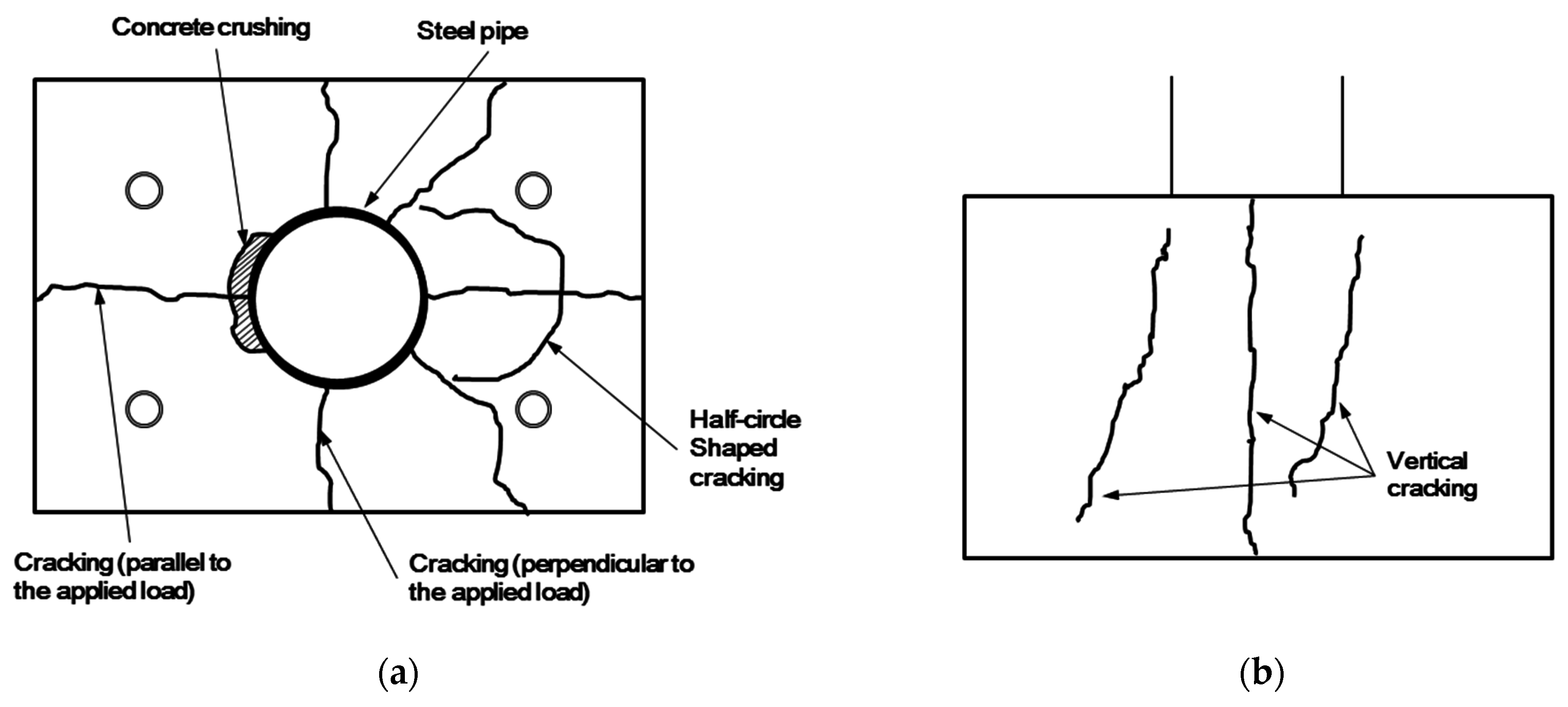
Table 3 summarizes the test results such as peak loads, displacements at peak loads, and loads corresponding to several crack propagation phenomena occurring in the concrete block. All of the test specimens basically showed very similar crack propagation patterns, which are illustrated in Figure 6. Cracking first occurred on top of the concrete block in the direction perpendicular to the lateral load (Stage 1) and then propagated into its side surfaces (Stage 2). As the load further increased, cracks were developed in the direction parallel to the lateral load appearing on top of the concrete block (Stage 3), and concrete crushing occurred on its compression side (Stage 4). In all of the test specimens, where the proposed perfobond shear connectors were installed, the crack pattern of a half circle shape was observed on top of the concrete block, as shown in Figure 6a. This phenomenon was not observed in the reference specimen SB_D10_NL, where the steel pile was strengthened with conventional steel rebars.
Figure 7 shows the cracking pattern of the reference specimen SB_D10_NL on its top and vertical faces. Cracks started to develop on the top and side surfaces of the concrete block in the direction perpendicular to the applied load at the load level (P) of 99 kN. As the load further increased, additional cracks were propagated on the top surface in the direction parallel to the applied load at P = 192 kN. Finally, concrete crushing occurred in the compression zone of the top surface at P = 277 kN, and the developed cracks were further propagated until the test specimen reached its complete failure stage.
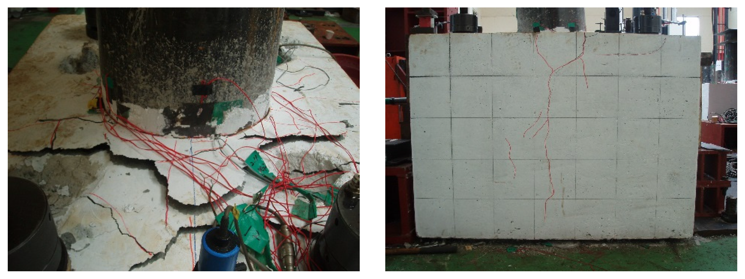
Figure 8 shows the cracking pattern of Specimen PO_D10_L6 on its top and side faces. This type of crack patterns was observed in all of the test specimens, where the proposed perfobond shear connectors were installed, although their peak load values were slightly different from each other. On the top surface of the concrete block, cracks started to develop in the direction perpendicular to the applied load at P = 69 kN and then were propagated into the side surface of the concrete cube at P = 78 kN. Top surface cracks were developed in the parallel direction to the applied load at P = 187 kN. Concrete crushing happened on top of the concrete cube at P = 235 kN. The test was over at P = 303 kN, when half-circle shaped cracks were intensively formed on the tension side of the top surface as shown in the figure.

3.2. Effects of Test Parameters on the Bending Resistance Capacity of the Strengthened Steel Pile Cap

This section discusses the effects of test parameters such as the type of perfobond shear connectors, infilled concrete depths, and the number of L-shaped steel plates on the bending resistance capacity of the steel pile cap strengthened with the proposed perfobond connectors. 
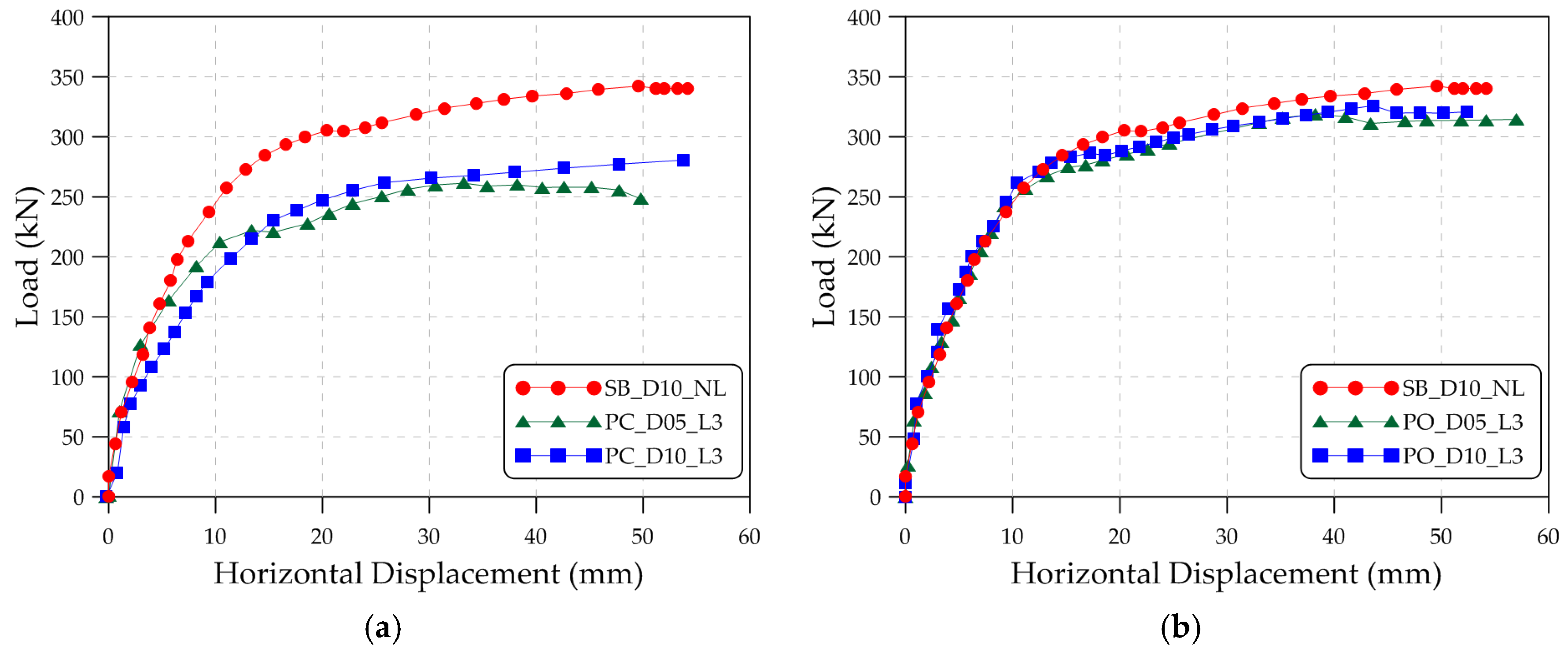
Figure 9a,b show the load-displacement curves of the D05_L3 and D10_L3 specimens to investigate the effect of perfobond shear connector types on their peak strengths, respectively. Here, D05_L3 specimens refer to the specimens with concrete infilled depth equal to the half of steel cap diameter (D05) and three L-shaped plates (L3). Hereafter, this notation is used throughout the section for convenience. The load-displacement curve of the reference specimen SB_D10_NL is also plotted in the two figures for comparison. The peak strengths and peak strength ratios of D05_L3 and D10_L3 specimens are listed in Table 4 and Table 5, respectively.
From these results, it can be seen that the specimens strengthened with the open-hole type perfobond connectors have higher bending resistance than those with the closed-hole type connectors, and almost equal strength to that of the reference specimen. For example, the ratios of the peak strength of the open-hole type perfobond specimens PO_D05_L3 and PO_D10_L3 to that of the reference specimen are 93.3% and 95.3%, respectively. This is remarkable considering that the concrete infilled depths of these specimens are only in the range of 200 mm and 400 mm, while that of the reference specimen is 700 mm as indicated in Table 1. Furthermore, as can be seen from Figure 9, their initial stiffness is almost equal to that of the reference specimen, and they retain the level of ductility comparable to that of the reference specimen. In addition, Table 4 and 
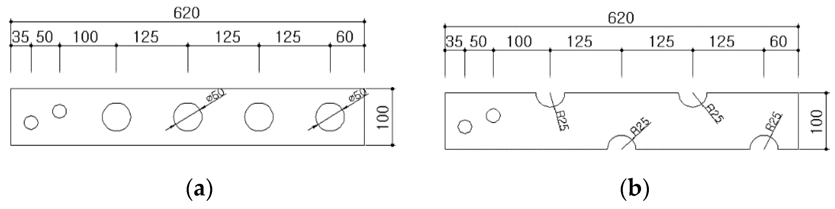
Table 5 show that their peak strengths are approximately 15% to 20% greater than those of the closed-hole type perfobond specimens. This seems to happen since the open-hole type perfobond connectors have a cross-sectional area larger than the open-hole type connectors as illustrated in Figure 3.
In order to examine the effect of concrete infilled depths on the bending resistance capacity of the specimens, the load-displacement curves of PC_L3 and PO_L3 specimens are plotted in Figure 10a,b, respectively. The load-displacement curve of the reference specimen is also included in the plot. Table 6 and Table 7 provide the peak strengths and peak strength ratios of these specimens.
It can be noted from these results that the peak strength of the specimen is increased with increasing concrete infilled depth. For example, in the case of PC_D10_L3 specimen, its peak strength is increased by 9.2% due to the increase of concrete infilled depth from 200 to 400 mm, while that of PO_D10_L3 specimen only by 2.2%. Therefore, the increase of peak strength due to increasing concrete infilled depth is more pronounced with closed-hole type perfobond specimens. As already observed previously, the open-hole type perfobond specimens have an approximately 10%–20% higher peak strength than those with closed-hole type perfobond connectors, and almost the same initial stiffness as the reference specimen.
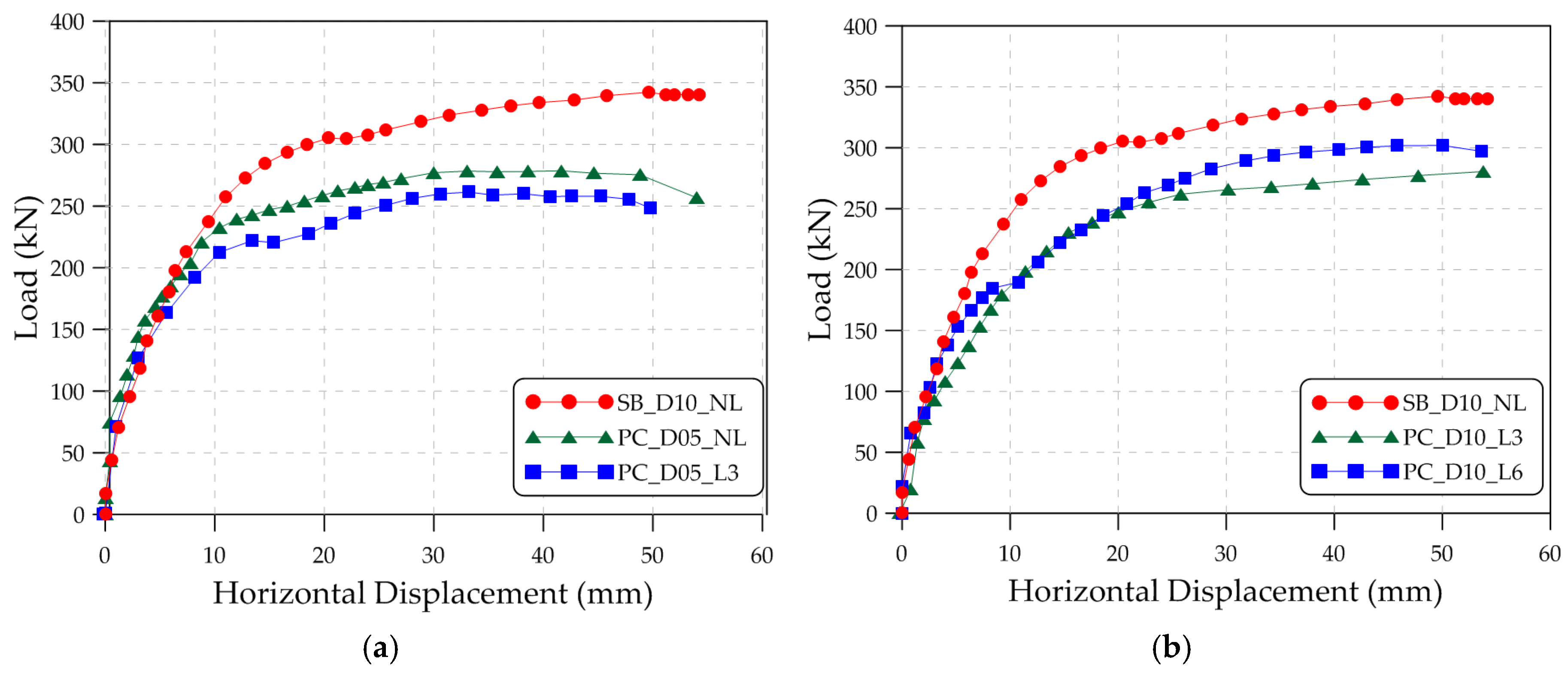
Figure 11a,b show the load-displacement curves of PC_D05 and PC_D10 specimens, respectively, and the effects of the number of L-shaped plates on the bending resistance capacity of the specimens are investigated. The load-displacement of the reference specimen is also included in both figures. Table 8 and Table 9 list the peak strengths and peak strength ratios of these specimens.
It can be seen from Figure 11a and Table 8 that the specimen with three L-shaped plates (PC_D05_L3) has a slightly smaller peak strength than the one with no L-shaped plates (PC_D05_NL). In contrast, Figure 11b and Table 9 indicate that the specimen with six L-shaped plates (PC_D10_L6) has a slightly higher peak strength than the one with three L-shaped plates (PC_D10_L3). As a consequence, it can be concluded that the number of L-shaped plates does not have a high impact on the bending resistance capacity of the specimen, and it may be impossible to install any of the L-shaped plates with the proposed perfobond shear connectors. Nonetheless, if L-shaped plates are installed, it is suggested that a number of the L-shaped plates should be symmetrically distributed with respect to the direction of lateral load.

4. Conclusions

In this study, an experimental investigation was performed on the structural performance of the steel pile cap strengthened with the proposed perfobond connectors under lateral loading. A bending test was conducted on seven specimens by considering the type of perfobond shear connectors, infilled concrete depth, and the number of L-shaped steel plates as test parameters. The failure characteristics of the test specimens were examined, and their load-displacement curves were analyzed. The main conclusions of this paper are as follows:
(1)
All of the test specimens basically showed very similar crack propagation patterns. Cracking first occurred on top of the concrete block in the direction perpendicular to the lateral load and then propagated into its side surfaces. As the load further increased, cracks in the direction parallel to the lateral load appeared on top of the concrete block, and concrete crushing occurred on its compression side.
(2)
In all of the test specimens, where the proposed perfobond shear connectors were installed, the crack pattern of a half circle shape was observed on top of the concrete block. In contrast, this phenomenon was not observed in the reference specimen, where the steel pile was strengthened with conventional steel rebars.
(3)
The specimens strengthened with the open-hole type perfobond connectors have almost the same bending resistance capacity as the reference specimen although the concrete infilled depths of the former are only in the range of approximately 29%–57% of the latter. Furthermore, their initial stiffness is almost equal to that of the reference specimen, and they also retain a level of ductility comparable to that of the reference specimen. The advantage of the proposed perfobond connectors mainly lies in its enhanced constructability although they did not show a significantly greater improvement in structural performance than the conventional rebar strengthening method.
(4)
The open-hole type perfobond specimens have approximately 10%–20% higher bending resistance capacity than those with closed-hole type perfobond connectors. The increase of peak strength due to increasing concrete infilled depth is more pronounced with closed-hole type perfobond specimens.
(5)
The number of L-shaped plates does not have a high impact on the bending resistance capacity of the specimen; thus, it may be impossible to install any of the L-shaped plates with the proposed perfobond shear connectors.

Acknowledgments

The corresponding author of this paper acknowledges support from the Basic Science Research Program through the National Research Foundation of Korea (NRF) funded by the Ministry of Science, ICT & Future Planning (Grant number: 2013R1A1A1076011).

Author Contributions

In this paper, Young-Ho Kim proposed the main concept of the new perfobond shear connector and prepared the experimental program to investigate its structural performance when subjected to lateral loading; Jae-Yoon Kang made a contribution to the implementation of the experimental program and discussed the test results; Sang-Ho Kim provided a suggestion on the overall organization of the paper and prepared the tables and figures included in the paper; Dae-Jin Kim provided the interpretation of the test results and wrote the entire manuscript.

Conflicts of Interest

The authors declare no conflict of interest.

References

  1. Joen, P.H.; Park, R. Simulated seismic load tests on prestressed concrete piles and pile-pile cap connections. PCI J. 1990, 35, 42–61. [Google Scholar] [CrossRef]
  2. Shama, A.A.; Mander, J.B.; Aref, A.J. Seismic Performance and Retrofit of Steel Pile to Concrete Cap Connections. ACI Struct. J. 2002, 99, 51–61. [Google Scholar]
  3. Kim, Y.-H.; Kim, J.-Y.; Koo, H.-B.; Kim, D.-J. Pull-out resistance capacity of a new perfobond shear connector for steel pile cap strengthening. Adv. Mater. Sci. Eng. 2016, in press. [Google Scholar] [CrossRef]
  4. Zellner, W. Recent designs of composite bridges and a new type of shear connectors. In Proceedings of the IABSE/ASCE Engineering Foundation Conference on Composite Construction, Henniker, NH, USA, 7–12 June 1987; pp. 240–252.
  5. Oguejiofor, E.C.; Hosain, M.U. A parametric study of perfobond rib shear connectors. Can. J. Civ. Eng. 1994, 21, 614–625. [Google Scholar] [CrossRef]
  6. Valente, I.; Cruz, P.J.S. Experimental analysis of Perfobond shear connection between steel and lightweight concrete. J. Constr. Steel Res. 2004, 60, 465–479. [Google Scholar] [CrossRef] [Green Version]
  7. Kim, H.-Y.; Jeong, Y.-J. Experimental investigation on behaviour of steel–concrete composite bridge decks with perfobond ribs. J. Constr. Steel Res. 2006, 62, 463–471. [Google Scholar] [CrossRef]
  8. Viannaa, J.D.C.; Costa-Nevesb, L.F.; Vellascoc, P.C.G.D.S.; de Andradea, S.A.L. Structural behaviour of T-Perfobond shear connectors in composite girders: An experimental approach. Eng. Struct. 2008, 30, 2381–2391. [Google Scholar] [CrossRef]
  9. Kim, S.-H.; Choi, K.-T.; Park, S.-J.; Park, S.-M.; Jung, C.-Y. Experimental shear resistance evaluation of Y-type perfobond rib shear connector. J. Constr. Steel Res. 2013, 82, 1–18. [Google Scholar] [CrossRef]
  10. Korea Rail Network Authority. Design Code of Railway Bridges; Ministry of Land, Infrastructure and Transport of Korea: Sejong, Korea, 2013.
  11. American Society for Testing and Materials International. Standard Test Method for Compressive Strength of Cylindrical Concrete Specimens; ASTM Standard C39/C39M-11; ASTM International: West Conshohocken, PA, USA, 2011. [Google Scholar]
  12. American Society for Testing and Materials International. Standard Test Methods and Definitions for Mechanical Testing of Steel Products; ASTM Standard A370-12a; ASTM International: West Conshohocken, PA, USA, 2012. [Google Scholar]
Figure 1. Perfobond shear connector for steel pile cap strengthening. (a) Perfobond shear connector with closed holes; (b) Perfobond shear connector with open holes; (c) Connection between the steel pile and perfobond shear connectors.
Applsci 06 00317 g001
Figure 2. Perfobond shear connector for steel pile cap strengthening. (a) Cutting of steel pile cap; (b) Hole punching on the steel pile cap; (c) Installation of perfobond shear connectors by bolting; (d) Distribution of steel reinforcing bars at concrete foundation.
Applsci 06 00317 g002
Figure 3. Details of test specimens. (a) Specimen strengthened with conventional steel rebars; (b) Specimen strengthened with perfobond shear connectors (unit: mm).
Applsci 06 00317 g003
Figure 4. Types of perfobond shear connectors. (a) Perfobond shear connector with closed holes; (b) Perfobond shear connectors with open holes (unit: mm).
Applsci 06 00317 g004
Figure 5. Test setup.
Applsci 06 00317 g005
Figure 6. Typical cracking patterns of test specimens. (a) Top surface of the concrete block; (b) Side surface of the concrete block.
Applsci 06 00317 g006
Figure 7. Failure mode of Specimen SB_D10_NL.
Applsci 06 00317 g007
Figure 8. Failure mode of Specimen PO_D10_L6.
Applsci 06 00317 g008
Figure 9. Effect of steel pile cap strengthening methods. (a) D05_L3 specimens; (b) D10_L3 specimens.
Applsci 06 00317 g009
Figure 10. Effect of infilled concrete depths. (a) PC_L3 specimens; (b) PO_L3 specimens.
Applsci 06 00317 g010
Figure 11. Effect of the number of L-shaped plates. (a) PC_D05 specimens; (b) PC_D10 specimens.
Applsci 06 00317 g011
Table 1. Details of test specimens.
Specimen NameType of StrengtheningInfilled Concrete Depth (mm)Number of L-Shaped Steel Plates (EA)
SB_D10_NLVertical rebars700 (≥1.0D)-
PC_D05_NLPerfobond shear connectors with closed holes200 (=0.5D)0
PC_D05_L33
PC_D10_L3400 (=1.0D)
PC_D10_L66
PO_D05_L3Perfobond shear connectors with open holes200 (=0.5D)3
PO_D10_L3400 (=1.0D)3
Table 2. Material properties of test specimens (unit: MPa (strength), % (strain)).
PropertiesConcreteRebarsSteel PileSteel Plate
H10H13H16H19H22SPS400SS400
compressive strength31.9-------
yield strength-607.5524.4490.1475.7579.6242.1321.4
ultimate strength-707.1650.9584.9581.8569.2418.8441.5
maximum strain at fracture-17.218.118.118.317.3-33.7
Table 3. Summary of the test results.
SpecimenCracking Load (kN)Peak LoadDisplacement at Peak Load (mm)
Stage 1Stage 2Stage 3Stage 4Lateral Load (kN)Bending Moment (kN∙m)
SB_D10_NL999919227734230850.0
PC_D05_NL8210816423927925132.2
PC_D05_L3587915022726223633.2
PC_D10_L3728619326528625768.6
PC_D10_L6697818723530327348.0
PO_D05_L3628421727331928739.2
PO_D10_L37415326228732629343.6
Table 4. Effect of steel pile cap strengthening methods for D05_L3 specimens.
SpecimenPeak Strength (kN)Ratio of Peak Strengths (%)
Divided by (•)Divided by (#1)
SB_D10_NL (•)342100.0-
PC_D05_L3 (#1)26276.6100.0
PO_D05_L3 (#2)31993.3121.8
Table 5. Effect of steel pile cap strengthening methods for D10_L3 specimens.
SpecimenPeak Strength (kN)Ratio of Peak Strengths (%)
Divided by (•)Divided by (#1)
SB_D10_NL (•)342100.0-
PC_D10_L3 (#1)28683.6100.0
PO_D10_L3 (#2)32695.3114.0
Table 6. Effect of infilled concrete depths for PC_L3 specimens.
SpecimenPeak Strength (kN)Ratio of Peak Strengths (%)
Divided by (•)Divided by (#1)
SB_D10_NL (•)342100.0-
PC_D05_L3 (#1)26276.6100.0
PC_D10_L3 (#2)28683.6109.2
Table 7. Effect of infilled concrete depths for PO_L3 specimens.
SpecimenPeak Strength (kN)Ratio of Peak Strengths (%)
Divided by (•)Divided by (#1)
SB_D10_NL (•)342100.0-
PO_D05_L3 (#1)31993.3100.0
PO_D10_L3 (#2)32695.3102.2
Table 8. Effect of the number of L-shaped plates for PC_D05 specimens.
SpecimenPeak Strength (kN)Ratio of Peak Strengths (%)
Divided by (•)Divided by (#1)
SB_D10_NL (•)342100.0-
PC_D05_NL (#1)27981.6100.0
PC_D05_L3 (#2)26276.693.9
Table 9. Effect of the number of L-shaped plates for PC_D10 specimens.
SpecimenPeak Strength (kN)Ratio of Peak Strengths (%)
Divided by (•)Divided by (#1)
SB_D10_NL (•)342100.0-
PC_D10_L3 (#1)28683.6100.0
PC_D10_L6 (#2)30388.6105.9

