Article

Nonlinear Adaptive Rotational Speed Control Design and Experiment of the Propeller of an Electric Micro Air Vehicle

College of Automation Engineering, Nanjing University of Aeronautics and Astronautics, 29 YuDao St., Nanjing 210016, China
*
Author to whom correspondence should be addressed.
Appl. Sci. 2016, 6(1), 17; https://doi.org/10.3390/app6010017
Submission received: 22 October 2015 / Revised: 30 December 2015 / Accepted: 8 January 2016 / Published: 13 January 2016

Abstract

:
Micro Air Vehicles (MAVs) driven by electric propellers are of interest for military and civilian applications. The rotational speed control of such electric propellers is an important factor for improving the flight performance of the vehicles, such as their positioning accuracy and stability. Therefore, this paper presents a nonlinear adaptive control scheme for the electric propulsion system of a certain MAV, which can not only speed up the convergence rates of adjustable parameters, but can also ensure the overall stability of the adjustable parameters. The significant improvement of the dynamic tracking accuracy of the rotational speed can be easily achieved through the combination of the proposed control algorithm and linear control methods. The experimental test results have also demonstrated the positive effect of the nonlinear adaptive control scheme on the flight performance of the MAV.

1. Introduction

In recent years, the study of Micro Air Vehicles (MAVs) driven by electric propellers has gained considerable momentum. Some substantial progress has been made towards designing, building and test-flying remotely piloted high-performance MAVs, and there exist many commercially available MAVs as well as laboratory prototypes [1,2,3]. Such MAVs are intended to lower the total system cost, and are easy enough to operate with minimal training. Moreover, the electric propellers can also reduce the noise signature in practical use.
In general, the thrust force of a MAV largely depends on the rotational speed of the electric propeller while the MAV performs low-speed flight missions [4], and the characteristics of the rotational speed system strongly affect the flight dynamics, stability and reliability of the MAV. Therefore, it is essential to develop a reliable control scheme to ensure an accurate rotational speed of the electric propeller, which can contribute to the significant improvement in the flight performance of the MAV, and new applications for both military and civilian markets.
The studies have been conducted for electric MAVs, as well as other propeller-based propulsion systems, mainly including multidisciplinary design optimization [5,6], system modeling [7,8,9], and control design [10,11,12,13,14,15]. Although the optimization of the electric propulsion systems of such MAVs is extremely crucial, most of the previous investigations were limited to either aerodynamic and structural analyses of propellers [16,17,18], or the optimization of electric motors [19,20]. Until recent times the rotational speed of the electric propeller was mainly regulated according to the altitude control signal without a closed loop speed control [21,22] or it was based on the linearized model around an operation point [23], thus resulting in degrading the flight performance of the MAV, such as the positioning accuracy and stability. Although the conventional method can guarantee the stability of the test plants with moderate flight performance, it largely depends on a lot of information and knowledge derived from the plants, and easily fails to achieve a satisfactory flight performance in the presence of parametric uncertainties.
The purpose of this study is to present a nonlinear adaptive control scheme for the electric propulsion system of a certain MAV, based on which the significant improvement in the dynamic tracking accuracy of the rotational speed can be easily achieved by further using linear control techniques. The control performance of the nonlinear adaptive controller is to be verified by a series of experimental tests.
This paper describes the rotational speed control problem of the propeller of the prototype electric MAV in Section 2. The modeling of the rotational speed system of the propeller is presented in Section 3, and Section 4 provides the nonlinear adaptive rotational speed control of the propeller. The experimental results are shown in Section 5. Finally, conclusions are drawn in Section 6.

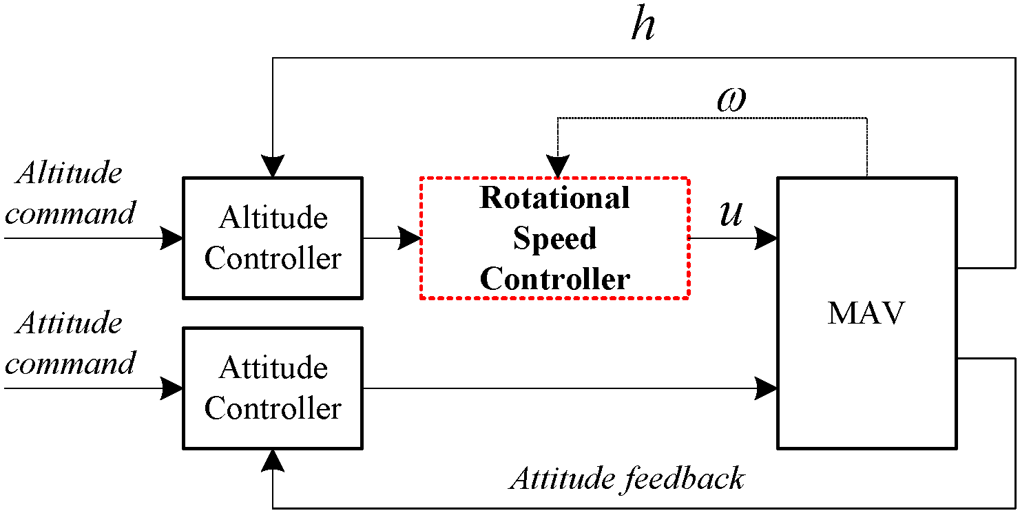
2. The Rotational Speed Control Problem of the Propeller of the Prototype Electric MAV

The prototype electric MAV, 0.8 m in height and 0.55 m in diameter, is shown in Figure 1. A duct is formed through the fuselage, and a propeller is mounted to the middle portion of the fuselage. Four deflecting vanes are mounted along the longitudinal and lateral axes of symmetry below the propeller to provide pitch, roll and yaw movements. Most of the anti-torque generated by the propeller is compensated by the stators configured inside the duct while the remaining anti-torque is balanced by the deflecting vanes. A center-symmetric landing gear consisting of four legs, i.e., left, right, front, back, made from glass fiber–reinforced plastics is installed on the MAV [2]. The propulsion system mainly consists of an advanced lithium battery, a brushless DC electric motor with an electronic speed controller (ESC), a subminiature encoder, and a propeller. The propeller driven by the electric motor can provide sufficient thrust force to lift the MAV.
Figure 1. The prototype electric Micro Air Vehicle (MAV).
Applsci 06 00017 g001
The rotational speed control of the electric propeller is desired for a high-performance MAV, because the characteristics of the rotational speed are nonlinear, and strongly affect the flight dynamics, stability and reliability of the MAV. It is, however, noted that, until recent times, the rotational speed of the electric propeller is only regulated according to the signal from a command signal generator without a closed-loop rotational speed control structure under fairly stable conditions, thus degrading the flight performance of the MAV. Therefore, the goal of this study is to design a reliable rotational speed controller for the electric propeller.

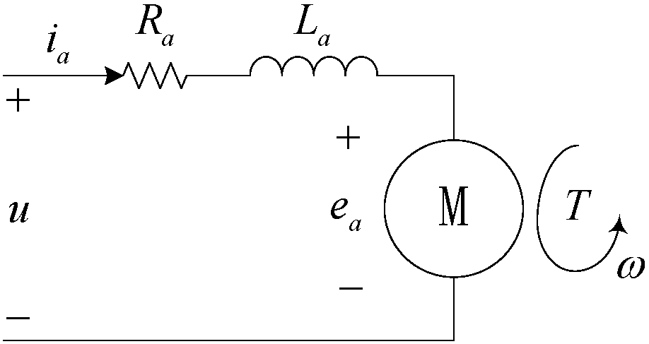
3. Modeling of the Rotational Speed System of the Propeller

The analysis of the basic principle model is crucial for the development of a proper controller to improve the control quality of the rotational speed system. With regard to the aim of this study, the schematic diagram of the motor that conveys detailed information about the electrical components of the motor is shown in Figure 2, where the no-load current is known and is compensated by the ESC.
Figure 2. The schematic diagram of the motor.
Applsci 06 00017 g002
The equations that describe the motor electrical components are as follows [24]:
u = R a i a + L a d i a d t + e a
e a = 1 K V ω
T = K Q i a
where u (V) is the armature voltage, i a (A) the armature current, R a (Ω) the armature coil resistance, L a (H) the armature coil inductance, e a (V) the back electromotive force, K V (rad/s/V) the motor voltage constant, K Q (Nm/A) the torque constant, T (Nm) the torque generated by the motor, ω (rad/s) the rotational speed of the motor.
Considering that the MAV performs low-speed flight missions, the propeller approximately produces a torque according to [25]
T p = k p ω p 2
where k p (Nm s2/rad2) is the propeller moment constant, T p (Nm) the propeller torque, ω p (rad/s) the rotational speed of the propeller.
The following conditions hold
ω p = ω , T p = T
under the assumption that the propeller is mounted on a propeller shaft which is driven through a rigid connection with the main drive shaft of the motor.
Substituting Equations (2) and (3) into Equation (1) yields
a 1 ω ω ˙ + a 0 ω 2 + b 0 ω = u
where a 1 = 2 L a k p K Q , a 0 = R a k p K Q , and b 0 = 1 K V . The characteristics of the rotational speed system in Equation (4) are a nonlinear differential equation, and the coefficients of the equation are difficult and expensive to accurately obtain in practice, which results in the fact that most existing autopilots for MAVs with electric propellers, such as the widely used Pixhawk® (Zurich, Switzerland) autopilot [26], only employ a proportional-integral-differential (PID) controller to simply and directly control the altitude without a closed-loop rotational speed control structure under fairly stable conditions. The behavior of the rotational speed directly and greatly affects the flight dynamics, and then indirectly and greatly affects the flight performance, such as the positioning accuracy and stability. The control of the rotational speed is therefore important to the improvement of the flight performance of the MAVs.
In addition, some reasonable assumptions must be made preliminarily to simplify the adaptive control design as follows:
a 1 > 0 , a 0 > 0 , b 0 > 0
u > 0 , ω > 0
It is finally noted that such assumptions are based on the fact that the rotational speed of the propeller remains high enough to lift the MAV.

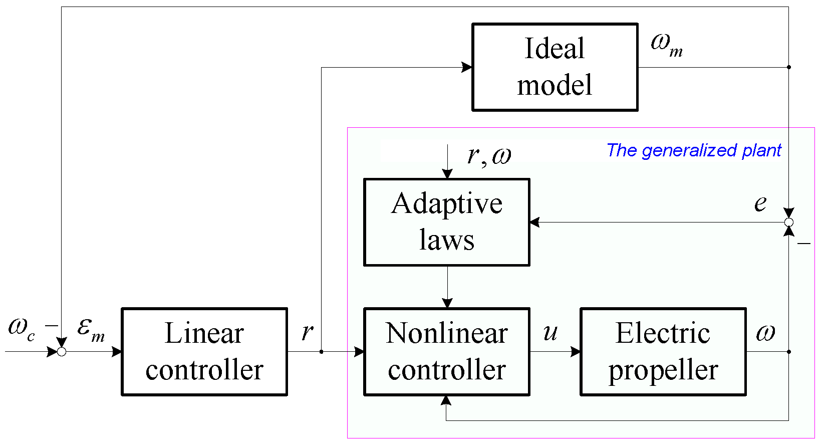
4. Nonlinear Adaptive Rotational Speed Control of the Propeller

4.1. Nonlinear Adaptive Control Algorithm

As for the rotational speed system in Equation (4), we first propose the following nonlinear control scheme:
u = k a 1 ω ω ˙ + k a 0 ω 2 + k b 0 ω + k b ω r
where r denotes the input signal of the rotational speed system; k a 1 , k a 0 , k b 0 and k b are adjustable parameters, which need to be tuned adaptively.
Substituting Equation (6) into Equation (4) yields
a ^ 1 ω ˙ + a ^ 0 ω + b ^ 0 = b ^ r
where
a ^ 1 = a 1 k a 1 , a ^ 0 = a 0 k a 0 , b ^ 0 = b 0 k b 0 , b ^ = k b
Thus far, the nonlinear differential equation of the rotational speed system in Equation (4) is found to be inevitably transformed into a linear form by using the nonlinear control scheme, which, however, can contribute to the simplification of the adaptive laws.
Referring to the above transformed model in Equation (7), the ideal model of the rotational speed system can be represented as:
a m 1 ω ˙ m + a m 0 ω m = b m r
where ω m is the model output; a m 1 , a m 0 and b m are the model parameters determined directly according to the desired performance requirements.
The tracking error between the outputs of the model and the plant
e = ω m ω
can then be derived as follows:
a m 1 e ˙ + a m 0 e = δ a 1 ω ˙ δ a 0 ω δ b 0 + δ b r
where
δ a 1 = a m 1 a ^ 1 , δ a 0 = a m 0 a ^ 0 , δ b 0 = b ^ 0 , δ b = b m b ^
As for the error system given by Equations (11), we consider the Lyapunov function candidate
V = 0.5 ( a m 1 e 2 + λ a 1 1 δ a 1 2 + λ a 0 1 δ a 0 2 + λ b 0 1 δ b 0 2 + λ b 1 δ b 2 )
where λ a 1 , λ a 0 , λ b 0 and λ b are optional positive numbers. From Equations (11) and (13), the derivative of the Lyapunov function candidate can then be derived as
V ˙ = a m 0 e 2 + δ a 1 ( λ a 1 1 δ ˙ a 1 e ω ˙ ) + δ a 0 ( λ a 0 1 δ ˙ a 0 e ω ) + δ b 0 ( λ b 0 1 δ ˙ b 0 e ) + δ b ( λ b 1 δ ˙ b + e r )
We assume that
{ δ ˙ a 1 = λ a 1 ( e ω ˙ + μ ω ˙ ) , δ ˙ a 0 = λ a 0 ( e ω + μ ω ) , δ ˙ b 0 = λ b 0 ( e + μ ) , δ ˙ b = λ b ( e r + μ r ) ,
where μ is an optional time-varying parameter and satisfies the condition:
sgn ( μ ) = sgn ( a m 1 e ˙ + a m 0 e )
The derivative of the Lyapunov function candidate can then be rewritten as follows:
V ˙ = a m 0 e 2 μ ( a m 1 e ˙ + a m 0 e )
Thus, we can conclude that V ˙ is a negative definite.
From Equations (8), (12) and (15), we can obtain the following adaptive laws:
{ k ˙ a 1 = λ a 1 ( e + μ ) ω ˙ , k ˙ a 0 = λ a 0 ( e + μ ) ω , k ˙ b 0 = λ b 0 ( e + μ ) , k ˙ b = λ b ( e + μ ) r .
It is worth noting that, in contrast with most existing adaptive laws, the term μ introduced here can contribute to the improvement of the convergence rates of adjustable parameters, as discussed below.
However, the nonlinear control algorithm cannot be normally executed at the zero rotational speed because the input signal r will be blocked in this case, as shown in Equation (6). Therefore, we should reset u = u min if ω < ω min and u < u min , where u min is a predefined minimum control value, ω min a predefined minimum rotational speed.

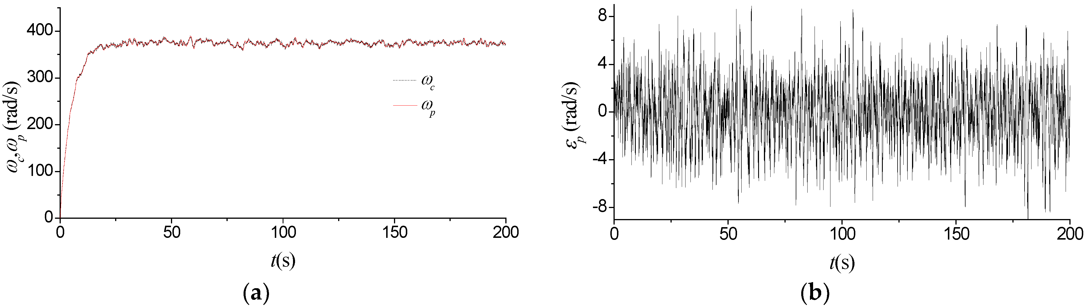
4.2. Comparative Analysis of the Learning Performance of the Proposed Adaptive Laws

In literatures, most existing adaptive laws for the similar system as that shown in Equation (7) do not contain the optional parameter μ , which is usually disadvantageous to the further improvement of the adaptive learning performance. It is important to note that the optional parameter μ in the proposed adaptive laws can significantly speed up the convergence rates of adjustable parameters. For example, as for the identical Lyapunov function candidate shown in Equation (13), we have
V ˙ = { a m 0 e 2 , μ = 0 a m 0 e 2 λ ( a m 1 e ˙ + a m 0 e ) 2 k + 2 , μ = λ ( a m 1 e ˙ + a m 0 e ) 2 k + 1 , k = 0 , ± 1 , a m 0 e 2 λ sgn ( a m 1 e ˙ + a m 0 e ) ( a m 1 e ˙ + a m 0 e ) , μ = λ sgn ( a m 1 e ˙ + a m 0 e )
where λ > 0 . From Equation (19), the introduced terms in V ˙ for the case with μ , such as e ˙ , can greatly contribute to the convergence rates of adjustable parameters. We can therefore conclude that the learning performance of the proposed algorithm with μ is superior to that without μ , such as most existing adaptive laws.
However, due to the unpredictability of the input signal, large amounts of experimental test results suggest that k ˙ a 1 , k ˙ a 0 , k ˙ b 0 and k ˙ b should be restricted in a bounded range by means of soft limiting strategies in order to avoid the over-learning problem of adjustable parameters and suppress the oscillation of adjustable parameters, as shown in Section 5. Here, k ˙ a 1 , k ˙ a 0 , k ˙ b 0 and k ˙ b are restricted as follows:
{ δ a 1 k ˙ a 1 δ a 1 , δ a 0 k ˙ a 0 δ a 0 , δ b 0 k ˙ b 0 δ b 0 , δ b k ˙ b δ b .
where δ a 1 , δ a 0 , δ b 0 and δ b are threshold values.
From an application perspective, the optional parameter μ , together with soft limiting strategies, can not only speed up the convergence rates of adjustable parameters, but can also ensure the overall stability of adjustable parameters, which is especially crucial for the flight safety of the MAV. It is finally important to note that, in fact, the determination of the optional parameter μ and the threshold values of soft limiting strategies according to the constraint condition in Equation (16) are dependent on some a priori information of the controlled system, such as the range of the input signal.

4.3. The Nonlinear Adaptive Control Diagram

For the controlled system given by Equation (7), the final design goal is generally to achieve a high-quality tracking performance. The schematic block diagram of the nonlinear adaptive control system, shown in Figure 3, is then constructed, where ω c denotes the command signal of the control system, ε m the error between the command signal ω c and the model output ω m .
Figure 3. The nonlinear adaptive control diagram.
Applsci 06 00017 g003
As mentioned above, the proposed adaptive laws are mainly used to accommodate parametric uncertainties and eliminate the tracking error e as much as possible, which can theoretically ensure that the generalized plant, mainly including the electric propeller and the nonlinear controller, asymptotically has the same characteristics as the ideal model in Equation (9), and based on this, the linear controller with the model feedback is designed to minimize the error ε m by means of linear control techniques. As a consequence, the rotational speed ω can precisely track the command signal ω c .

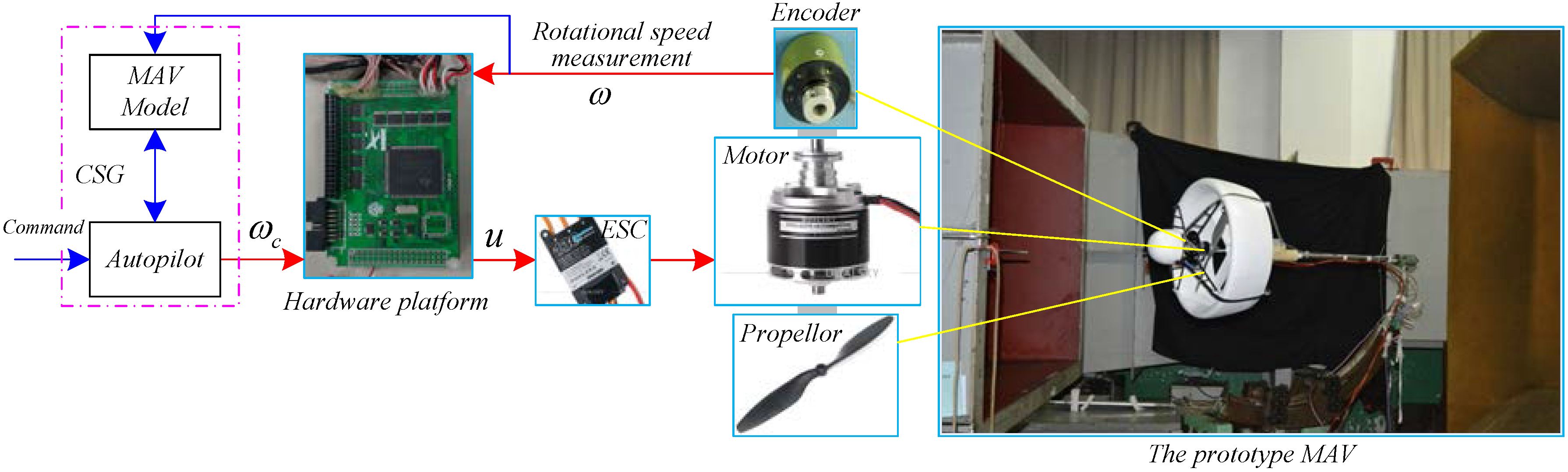
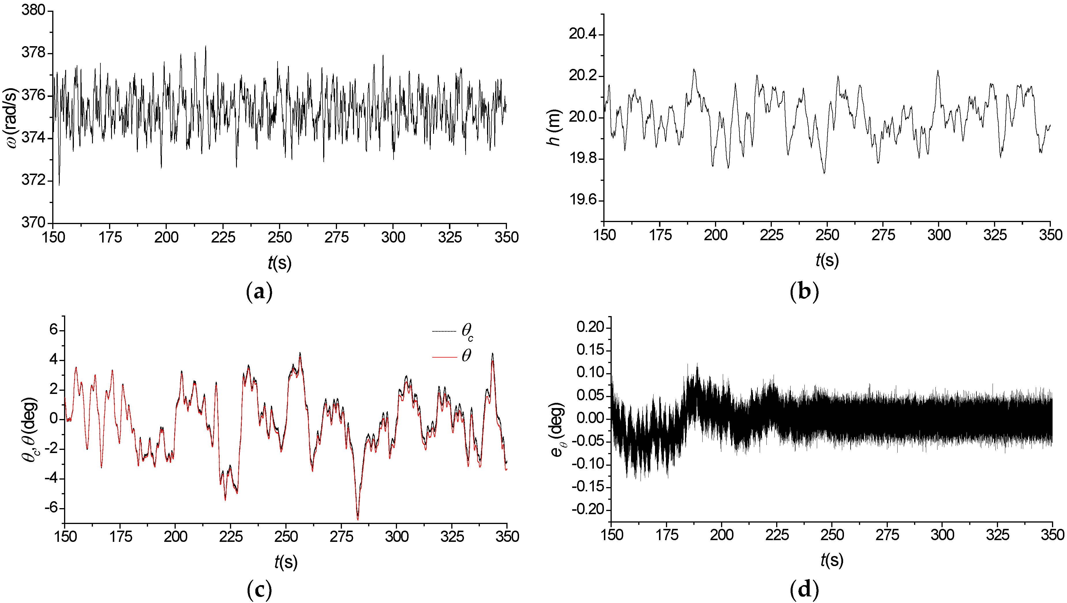
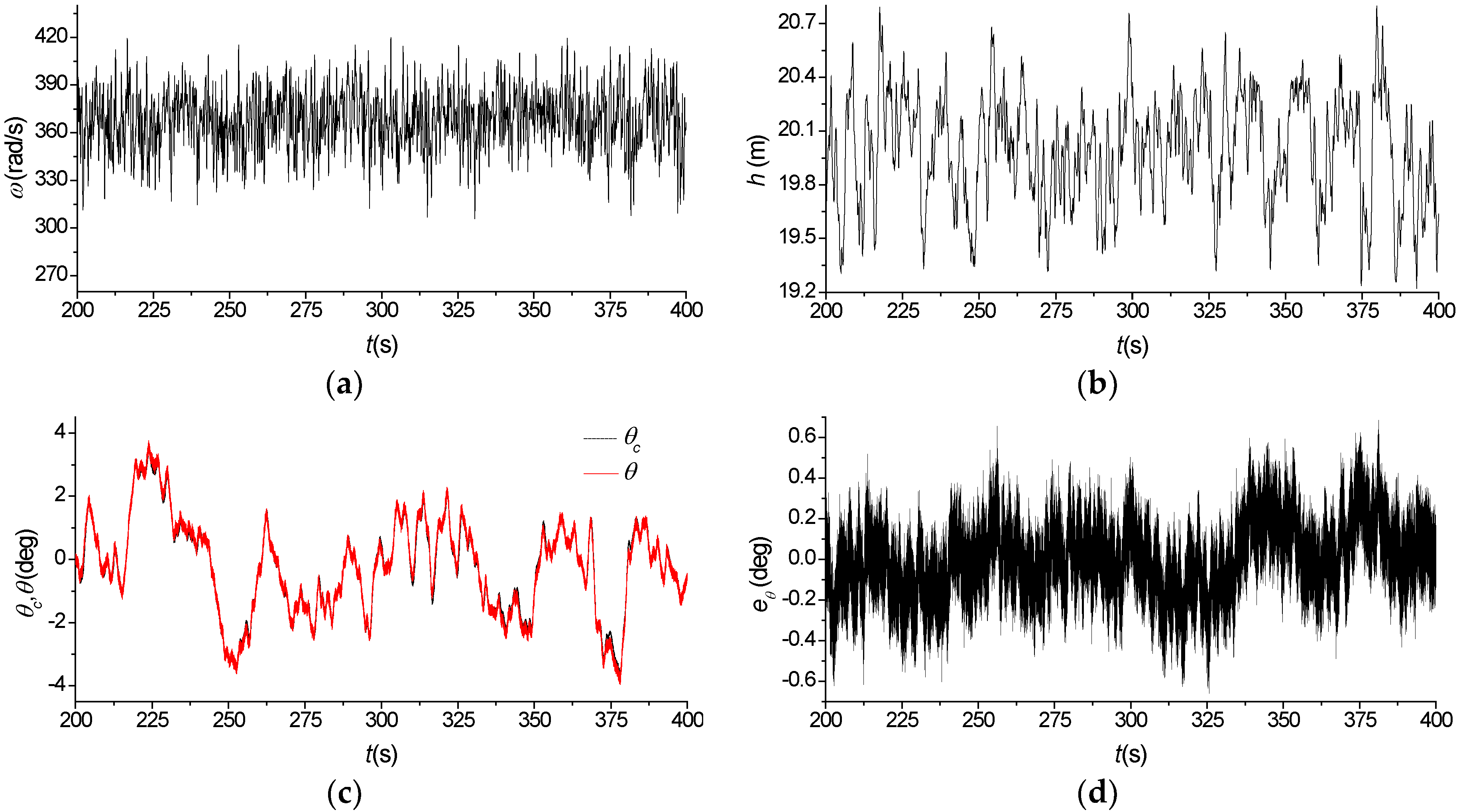
5. Experimental Tests

In this section, we will first describe the details of the real-time hardware-in-loop (HIL) experimental setup used for validation purposes. Finally, extensive experimental tests will be carried out along with necessary discussions and evaluations.

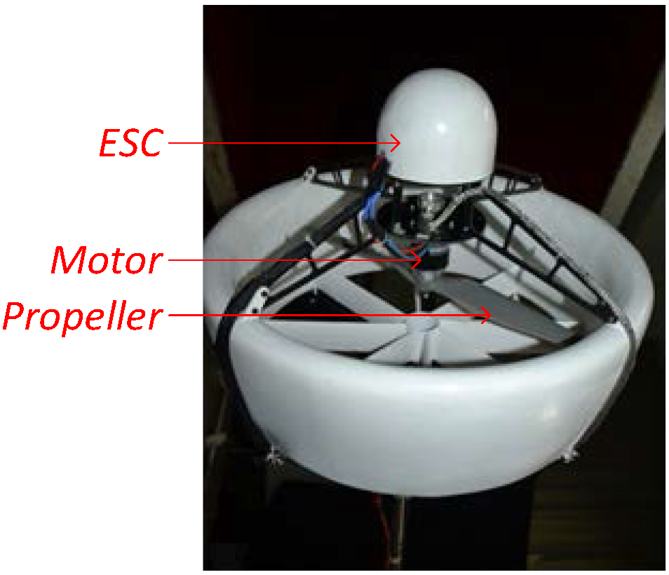
5.1. The HIL Experimental Setup and Description

The component parts of the rotational speed system, mainly including a propeller, a DC motor with an ESC (DUΛLSKY® XM6355DA and XC9036HV, Shanghai, China), a subminiature encoder with resolution of 20 (JL25, Changchun Institute of Optics, Changchun, Jilin, China), and a digital signal processor (DSP)-based hardware platform with an optional high resolution external timer module, are shown in Figure 4. The software of the nonlinear adaptive control system runs on the hardware platform that can provide reliable support for high precision timer and synchronization operations. The subminiature high resolution incremental encoder is mounted on the end of the main drive shaft to measure the actual rotational speed of the propeller. The command signal generator, including a MAV mathematical model and an autopilot, is normally used to generate the command signal used as input to the rotational speed system according to the flight missions. The schematic diagram of the experimental setup is shown in Figure 4, but to be safe, the MAV is fixed to a post.
Figure 4. The hardware-in-loop (HIL) experimental setup.
Applsci 06 00017 g004
Considering that the propeller only rotates in a fixed direction, namely a clockwise direction or a counter-clockwise direction, the actual rotational speed of the propeller can be determined by scanning the interval time between two neighboring A-phase or B-phase pulses from the incremental encoder, which is implemented based on the high resolution external timer module on the hardware platform.
The predefined parameters are described as follows:
(1)
Model parameters: a m 1 = 1 . 0 × 10 4 , a m 0 = 5 . 0 × 10 3 , b m = 7 . 5 × 10 2 ;
(2)
Initial values of adjustable parameters: k a 1 ( 0 ) = 4 . 0 × 10 4 , k a 0 ( 0 ) = 0 , k b 0 ( 0 ) = 5 . 5 × 10 3 ;
(3)
Adjustable parameter: k b ( t ) 1 . 5 × 10 2 ;
Adaptive learning algorithm: λ a 1 = 1 . 0 × 10 5 , λ a 0 = 2 . 0 × 10 7 , λ b 0 = 1 . 0 × 10 4 , μ = 100 ( a m 1 e ˙ + a m 0 e ) ;
(4)
Soft limiting elements: k ˙ a 1 , k ˙ a 0 , k ˙ b 0 , k ˙ b ( 1 . 0 × 10 3 , 1 . 0 × 10 3 ) ;
(5)
Linear controller: PID controller.
On the one hand, the proper choice of the initial values of adjustable parameters can speed up the convergence rates of the adjustable parameters, while, on the other hand, from Equations (7) and (9), k b can be artificially fixed to reduce the learning variables and simplify the adaptive learning task without any modification of the adaptive laws, both of which can contribute to the adaptive learning performance. Otherwise, the adaptive learning process of adjustable parameters probably lasts longer. Then, a series of real-time HIL experimental tests are conducted to assess the control performance of the proposed nonlinear adaptive control scheme based on the above assumption.

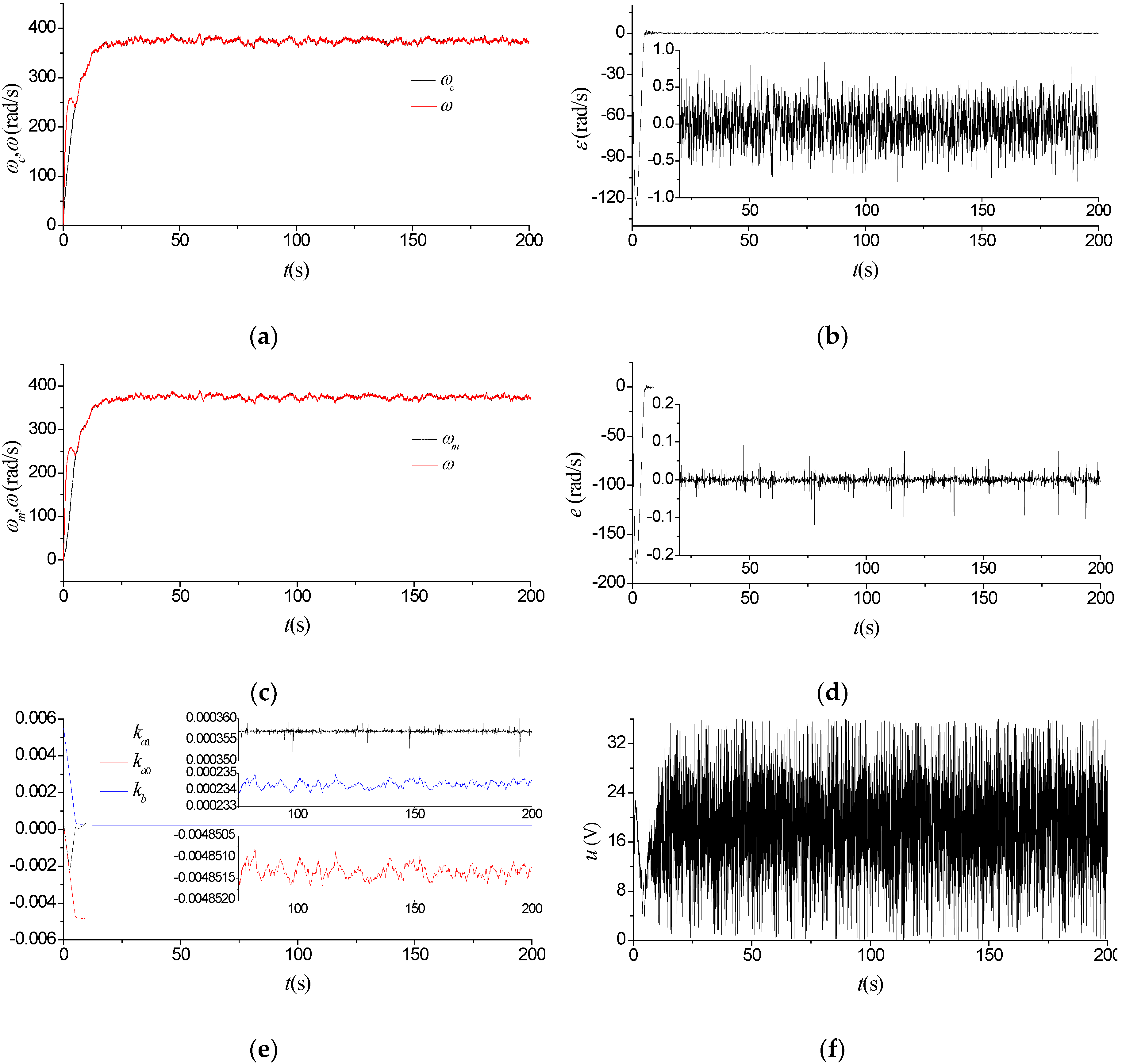
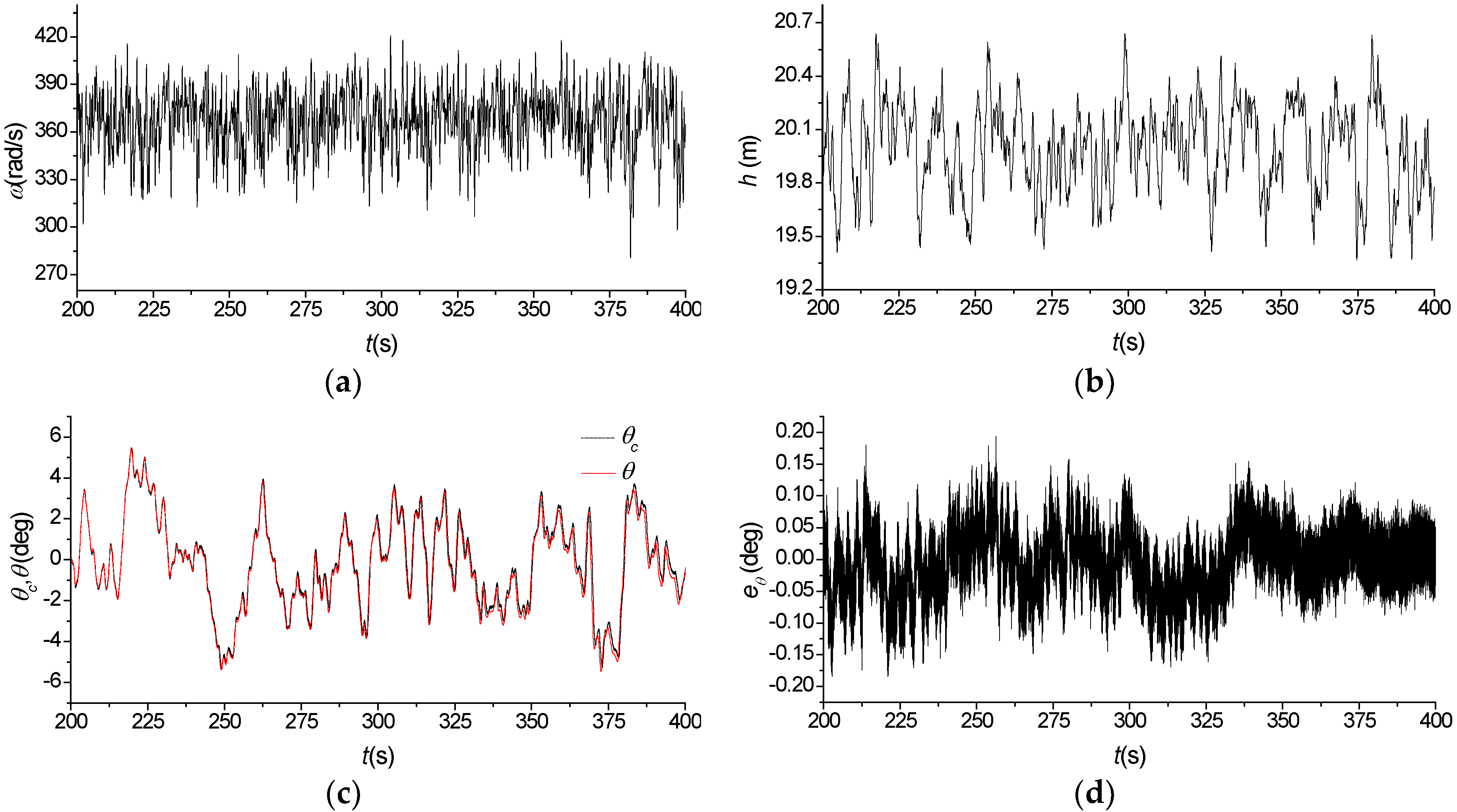
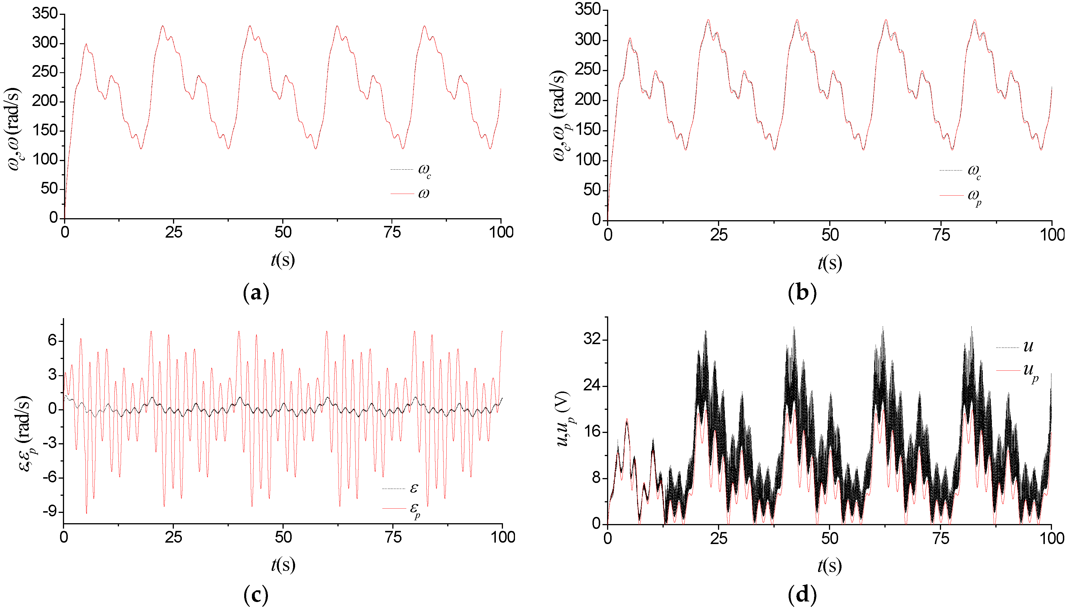
5.2. Experimental Tests and Discussions

Figure 5 shows the experimental results of the proposed nonlinear control scheme during take-off and hovering flight. It is illustrated from Figure 5a–d that the resulting controlled system can achieve a good tracking performance within about 10 s even without any reliable and accurate a priori information about the behavior of the rotational speed system, where ε denotes the tracking error between the command signal ω c and the actual rotational speed ω . Thereafter, the tracking error typically remains in the range of 0.75 rad/s, which is sufficient to meet the application requirements of a high-performance MAV. Meanwhile, the adjustable parameters of the nonlinear controller also have good convergence properties as shown in Figure 5e, although they finally fluctuate more or less around their mean values. It is, however, to note that the control signal from the nonlinear controller changes rapidly with time, as shown in Figure 5f.
Figure 5. Experimental results of the nonlinear adaptive control scheme. (a) ω c and ω ; (b) ε ; (c) ω m and ω ; (d) e ; (e) Adjustable parameters; (f) u .
Applsci 06 00017 g005
Figure 6 shows the learning process of adjustable parameters with different μ or without soft limiting elements. The increase of μ can obviously contribute to the convergence of adjustable parameters; however, this results in the significant fluctuations of adjustable parameters in the later stage of the learning process mainly because of measurement noises. It is even worse that the adjustable parameters exhibit sharp fluctuations for a longer period of time if removing the soft limiting elements from the nonlinear adaptive control scheme, as shown in Figure 6b, which can easily render the over-learning problem of adjustable parameters.
Figure 6. Comparisons of the learning process of adjustable parameters. (a) Adjustable parameters with soft limiting elements: Case 1: μ = 0 , Case 2: μ = 1000 ( a m 1 e ˙ + a m 0 e ) ; (b) Adjustable parameters without soft limiting elements.
Applsci 06 00017 g006
Figure 7 presents the experimental results of the optimized PID controller, with the nonlinear controller removed from the control scheme, where ω p is the rotational speed, u p the controller output, ε p the tracking error between ω c and ω p in this test case. In contrast to what has been shown in Figure 5, the tracking error increases significantly from 0.75 rad/s to 8.0 rad/s, although the control performance is basically acceptable in practice, which also comparatively demonstrates that the proposed nonlinear control scheme can contribute to the significant improvement in the control performance, as shown in Figure 8.
Figure 7. Experimental results of the optimized proportional-integral-differential (PID) controller. (a) ω c and ω p ; (b) ε p .
Applsci 06 00017 g007
Figure 8. Comparisons of some experimental results of two types of control schemes. (a) ε and ε p ; (b) u and u p .
Applsci 06 00017 g008
Figure 9 shows the comparisons of some experimental results of two types of control schemes in a wide range of rotational speeds, where the initial values of the adjustable parameters of the nonlinear controller are set to the final values obtained in the first experimental test shown in Figure 5e. The results have once again verified that the dynamic tracking accuracy of the proposed nonlinear adaptive control scheme is much more satisfactory than that of the optimized PID controller, as shown in Figure 9a–c. It is of further note that the achievements largely depend on the fast control capability of the proposed nonlinear adaptive controller, as shown in Figure 9d.
Figure 9. Comparisons of some experimental results of two types of control schemes in a wide range of rotational speeds: (a) ω c and ω ; (b) ω c and ω p ; (c) ε and ε p ; (d) u and u p .
Applsci 06 00017 g009

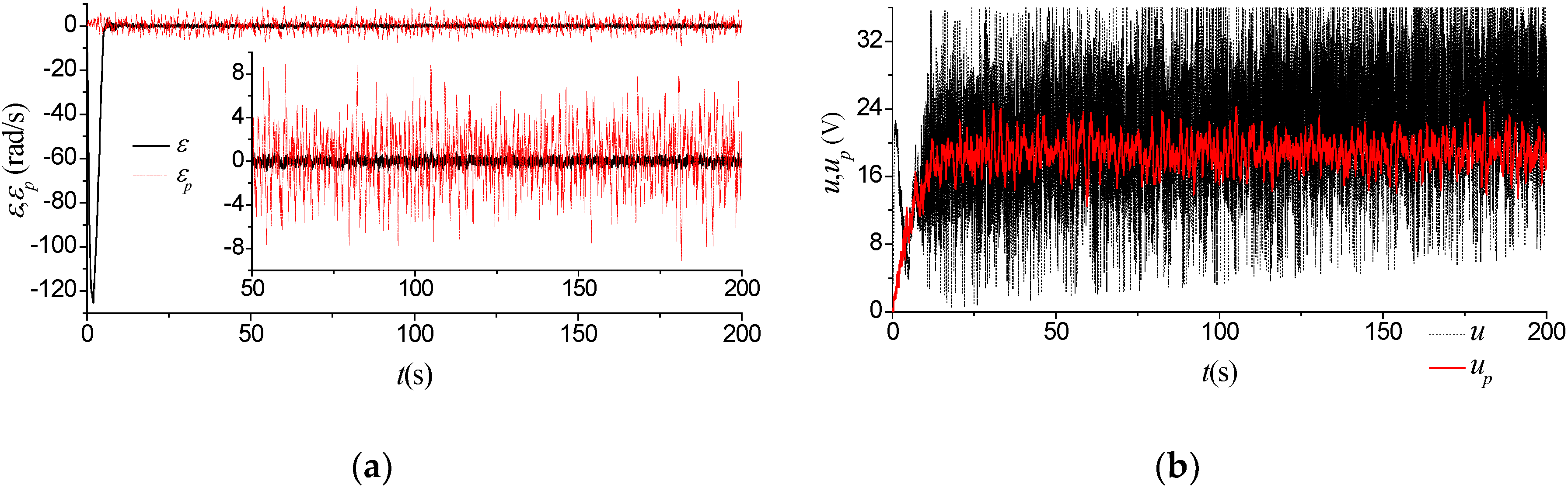
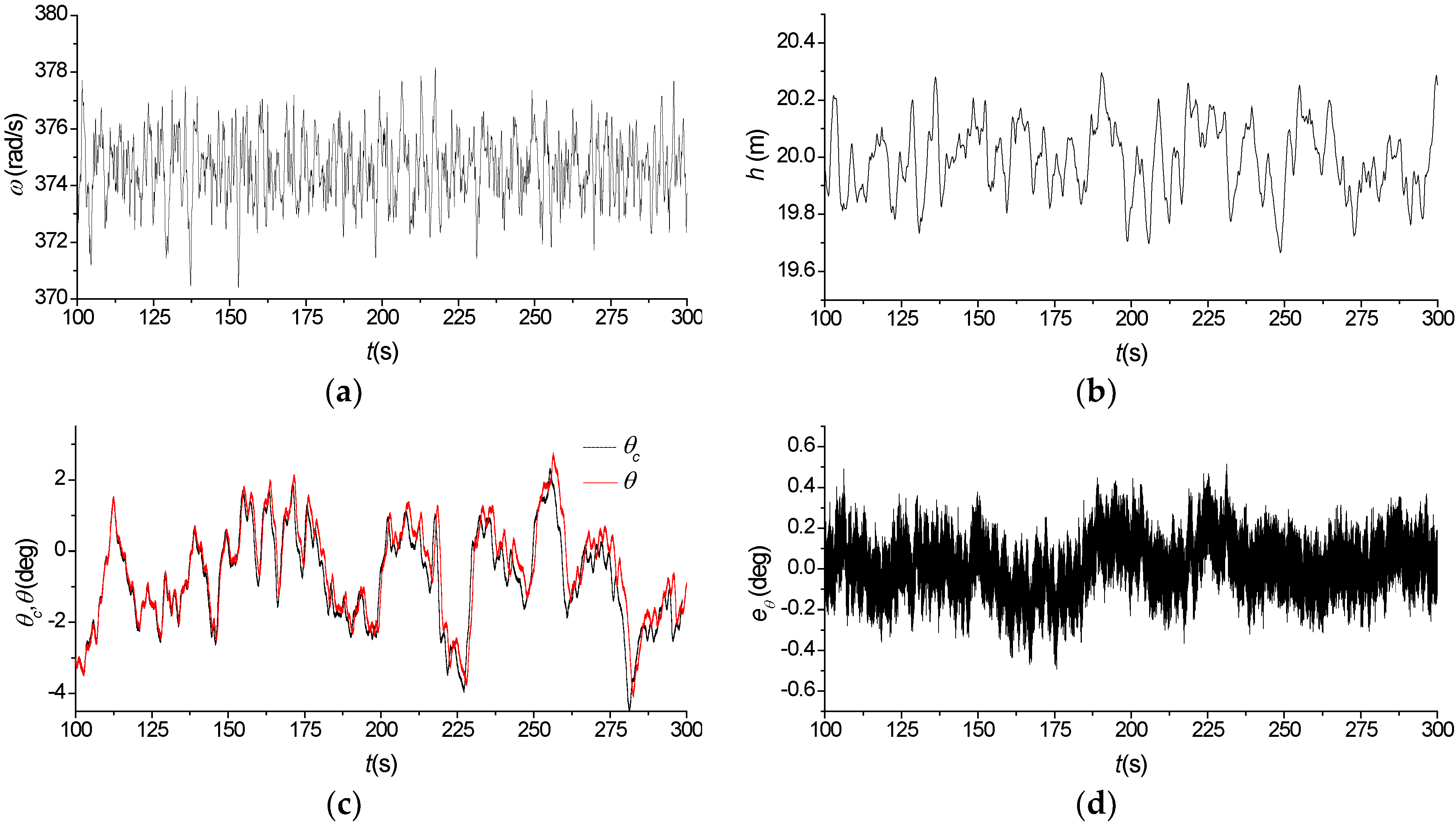
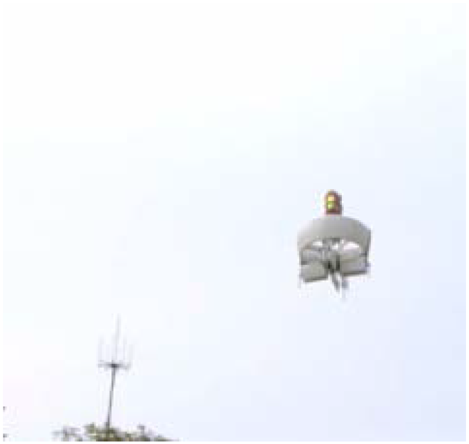
5.3. Flight Tests and Discussions

In this subsection, the positive effect of the proposed adaptive rotational speed control strategy on the flight performance of the MAV is comparatively demonstrated by a series of flight tests. The control scheme for the flight tests is shown in Figure 10, where we employ the existing adaptive controllers in [2] or PID controllers in the altitude loops, and the PID controller with or without the closed-loop rotational speed control structure in the altitude loop. For the MAV, the control software runs on the DSP platform, and the sensor units mounted on the top of the fuselage are provided with the measured states of the MAV. In order to ensure the flight test safety, the following steps are conducted: (i) vertical take-off to 20 m above the ground; (ii) holding altitude, as shown in Figure 11. During flight, the serial-based data links provide a link to the ground station computer that allows monitoring the real-time flight information and uploading remote control commands such as the altitude command signals from the manual control unit.
Figure 10. The control scheme.
Applsci 06 00017 g010
Figure 11. Flight test.
Applsci 06 00017 g011
Some experimental results are comparatively shown in Figure 12 and Figure 13 or Figure 14 and Figure 15, where h is the flight height of the MAV above the ground; θ c and θ are the pitch command signal and the pitch of the MAV; e θ is the tracking error between θ c and θ . The comparison of the experimental results demonstrates that (1) the proposed control scheme can significantly improve the control accuracy of the flight height of the MAV from about 0.8 m to 0.3 m, as comparatively shown in Figure 12b and Figure 13b or Figure 14b and Figure 15b; and (2) that the proposed control scheme can effectively and greatly suppress the oscillation of the rotational speed of the propeller from the approximate range of 100 rad/s to 6 rad/s, as comparatively shown in Figure 12a and Figure 13a or Figure 14a and Figure 15a. The positive effect of the proposed control scheme on the altitude tracking performance is somewhat obvious in different cases, and the altitude tracking error is averagely reduced by more than 50%, as comparatively shown in Figure 12d and Figure 13d or Figure 14d and Figure 15d. We can therefore conclude that the proposed adaptive rotational speed control scheme can contribute to the significant improvement of the flight performance of the MAV.
Figure 12. The experimental results using the existing adaptive controllers in the altitude loops, and the PID controller without the closed-loop rotational speed control structure in the altitude loop: (a) ω ; (b) h ; (c) θ c and θ ; (d) e θ .
Applsci 06 00017 g012
Figure 13. The experimental results using the existing adaptive controllers in the altitude loops, and the PID controller with the closed-loop rotational speed control structure in the altitude loop: (a) ω ; (b) h ; (c) θ c and θ ; (d) e θ .
Applsci 06 00017 g013
Figure 14. The experimental results using the PID controllers in the altitude loops, and the PID controller without the closed-loop rotational speed control structure in the altitude loop: (a) ω ; (b) h ; (c) θ c and θ ; (d) e θ .
Applsci 06 00017 g014
Figure 15. The experimental results using the PID controllers in the altitude loops, and the PID controller with the closed-loop rotational speed control structure in the altitude loop: (a) ω ; (b) h ; (c) θ c and θ ; (d) e θ .
Applsci 06 00017 g015
It is finally noted that from the comparison of the experimental results, the proposed adaptive rotational speed control scheme can directly and significantly improve the control quality of the rotational speed of the propeller, which further results in the improvement of the control qualities of the flight height and altitude. It is therefore demonstrated both theoretically and experimentally that the proposed control scheme is effective and essential to further improving the overall flight performance of such MAVs.

6. Conclusions

This paper presents the nonlinear adaptive control development for the rotational speed system of the propeller of the prototype electric MAV. The proposed nonlinear adaptive control scheme can contribute to the simplification of the generalized plant, based on which the significant improvement in the dynamic tracking accuracy of the rotational speed can be easily achieved by further using linear control techniques. The experimental test results have demonstrated the performance of the nonlinear adaptive controller. Note that the nonlinear adaptive control scheme can provide quite a satisfactory tracking accuracy from the beginning, given the learned parameters.
The resulting dynamic tracking accuracy of the rotational speed is sufficient to meet the application requirements of a high-performance MAV.

Acknowledgments

This study was supported in part by National Natural Science Foundation of China (NSFC) (Under Grant No. 61374188), Natural Science Foundation of Jiangsu Province of China (Under Grant No. BK20141412), Applied Basic Research Programs of Natural Science Foundation of Jiangsu Province, China (Under Grant No. BY2015003-10), the Fundamental Research Funds for the Central Universities under Grant No. NP2014601.

Author Contributions

All authors discussed the contents of the manuscript. Shouzhao Sheng contributed to the research idea and the framework of this study. Chenwu Sun completed the realization of the test bench and the experimental work.

Conflicts of Interest

The authors declare no conflict of interest.

References

  1. Sheng, S.; Sun, C. A Near-Hover Adaptive Attitude Control Strategy of a Ducted Fan Micro Aerial Vehicle with Actuator Dynamics. Appl. Sci. 2015, 5, 666–681. [Google Scholar] [CrossRef]
  2. Sheng, S.; Sun, C.; Zhao, H. Indirect Adaptive Attitude Control for a Ducted Fan Vertical Takeoff and Landing Microaerial Vehicle. Math. Probl. Eng. 2015, 2015, 1–11. [Google Scholar]
  3. Morris, S.; Holden, M. Design of micro air vehicles and flight test validation. In Proceeding of the Coference on Fixed, Flapping and Rotary Wing Vehicles at Very Low Reynolds Numbers, Notre Dame, IN, USA, 5–7 June 2000; pp. 153–176.
  4. Jung, D.; Tsiotras, P. Modeling and hardware-in-the-loop simulation for a small unmanned aerial vehicle. In Proceedings of the AIAA Infotech at Aerospace 2007 conference and exhibit, Rohnert Park, CA, USA, 7–10 May 2007.
  5. Martin, P.; Boxwell, D. Design, analysis and experiments on a 10-inch ducted rotor VTOL UAV. In Proceedings of the American Helicopter Society (AHS) International Specialists Meeting on Unmanned Rotorcraft: Design, Control and Testing, American Helicopter Society, Phoenix, AZ, USA, 18–20 January 2005; pp. 18–20.
  6. Pereira, J.; Chopra, I.; Gessow, A. Effects of shroud design variables on hover performance of a shrouded rotor for micro air vehicle applications. In Proceedings of the AHS International Specialists’ Meeting on Unmanned Rotorcraft, American Helicopter Society, San Marcos, CA, USA, 18–20 January 2005.
  7. Salluce, D.N. Comprehensive System Identification of Ducted Fan UAVs. Ph.D. Thesis, California Polytechnic State University, San Luis Obispo, CA, USA, January 2004. [Google Scholar]
  8. Ko, A.; Ohanian, O.J.; Gelhausen, P. Ducted fan UAV modeling and simulation in preliminary design. In Proceedings of the AIAA modeling and simulation technologies conference and exhibit, Keystone, CO, USA, 20–23 August 2007.
  9. Johnson, E.N.; Turbe, M.A. Modeling, control, and flight testing of a small ducted fan aircraft. J. Guid. Control Dyn. 2006, 29, 769–779. [Google Scholar] [CrossRef]
  10. Metni, N.; Pflimlin, J.M.; Hamel, T.; Soueres, P. Attitude and gyro bias estimation for a VTOL UAV. Control Eng. Pract. 2006, 14, 1511–1520. [Google Scholar] [CrossRef]
  11. Peddle, I.K.; Jones, T.; Treurnicht, J. Practical near hover flight control of a ducted fan (SLADe). Control Eng. Pract. 2009, 17, 48–58. [Google Scholar] [CrossRef]
  12. Sheng, S.; Mian, A.A.; Zhao, C.; Jiang, B. Autonomous take-off and landing control for a prototype unmanned helicopter. Control Eng. Pract. 2010, 18, 1053–1059. [Google Scholar] [CrossRef]
  13. Naldi, R.; Gentili, L.; Marconi, L.; Sala, A. Design and experimental validation of a nonlinear control law for a ducted-fan miniature aerial vehicle. Control Eng. Pract. 2010, 18, 747–760. [Google Scholar] [CrossRef]
  14. Pflimlin, J.M.; Soueres, P.; Hamel, T. Position control of a ducted fan VTOL UAV in crosswind. Int. J. Control 2007, 80, 666–683. [Google Scholar] [CrossRef]
  15. Pflimlin, J.M.; Binetti, P.; Soueres, P.; Hamel, T.; Trouchet, D. Modeling and attitude control analysis of a ducted-fan micro aerial vehicle. Control Eng. Pract. 2010, 18, 209–218. [Google Scholar] [CrossRef]
  16. Gur, O.; Rosen, A. Optimizing Electric Propulsion Systems for Unmanned Aerial Vehicles. J. Aircr. 2009, 46, 1340–1353. [Google Scholar] [CrossRef]
  17. Sinibaldi, G.; Marino, L. Experimental analysis on the noise of propellers for small UAV. Appl. Acoust. 2013, 74, 79–88. [Google Scholar] [CrossRef]
  18. Uragun, B.; Tansel, I.N. The noise reduction techniques for unmanned air vehicles. In Proceedings of the 2014 International Conference on Unmanned Aircraft Systems, Orlando, FL, USA, 27–30 May 2014; pp. 800–807.
  19. Ragot, P.; Markovic, M.; Perriard, Y. Optimization of electric motor for a solar airplane application. IEEE Trans. Ind. Appl. 2006, 42, 1053–1061. [Google Scholar] [CrossRef]
  20. Green, C.R.; McDonald, R.A. Modeling and Test of the Efficiency of Electronic Speed Controllers for Brushless DC Motors. In Proceedings of the 15th AIAA Aviation Technology, Integration, and Operations Conference, Dallas, TX, USA, 22–26 June 2015; pp. 3191–3200.
  21. Beard, R.W. Quadrotor Dynamics and Control; Brigham Young University: Provo, UT, USA, 2008. [Google Scholar]
  22. Shirsat, A.R. Modeling and Control of a Quadrotor Aircraft UAV. Ph.D. Thesis, Arizona State University, Tempe, AZ, USA, May 2015. [Google Scholar]
  23. Bouabdallah, S.; Murrieri, P.; Siegwart, R. Design and control of an indoor micro quadrotor. In Proceedings of the 2004 IEEE International Conference on Robotics and Automation, New Orleans, LA, USA, 26 April–1 May 2004; Volume 5, pp. 4393–4398.
  24. Hanselman, D.C. Brushless Permanent Magnet Motor Design, 2nd ed.; The Writers’ Collective: Cranston, RI, USA, 2003; pp. 183–201. [Google Scholar]
  25. Johnson, W. A Comprehensive Analytical Model of Rotorcraft Aerodynamics and Dynamics. Part 1. Analysis Development; National Aeronautics and Space Administration Moffett Field CA Ames Research Center: Moffett Field, CA, USA, 1980. [Google Scholar]
  26. PX4 Autopilot. Available online: https://pixhawk.org/choice (accessed on 12 December 2015).

