Abstract
Composites of ferromagnetic and ferroelectric phases are of interest for studies on mechanical strain-mediated coupling between the two phases and for a variety of applications in sensors, energy harvesting, and high-frequency devices. Nanocomposites are of particular importance since their surface area-to-volume ratio, a key factor that determines the strength of magneto-electric (ME) coupling, is much higher than for bulk or thin-film composites. Core–shell nano- and microcomposites of the ferroic phases are the preferred structures, since they are free of any clamping due to substrates that are present in nanobilayers or nanopillars on a substrate. This review concerns recent efforts on ME coupling in coaxial fibers of spinel or hexagonal ferrites for the magnetic phase and PZT or barium titanate for the ferroelectric phase. Several recent studies on the synthesis and ME measurements of fibers with nickel ferrite, nickel zinc ferrite, or cobalt ferrite for the spinel ferrite and M-, Y-, and W-types for the hexagonal ferrites were considered. Fibers synthesized by electrospinning were found to be free of impurity phases and had uniform core and shell structures. Piezo force microscopy (PFM) and scanning microwave microscopy (SMM) measurements of strengths of direct and converse ME effects on individual fibers showed evidence for strong coupling. Results of low-frequency ME voltage coefficient and magneto-dielectric effects on 2D and 3D films of the fibers assembled in a magnetic field, however, were indicative of ME couplings that were weaker than in bulk or thick-film composites. A strong ME interaction was only evident from data on magnetic field-induced variations in the remnant ferroelectric polarization in the discs of the fibers. Follow-up efforts aimed at further enhancement in the strengths of ME coupling in core–shell composites are also discussed in this review.
1. Introduction
Single phase and composite multiferroics have been of significant interest for studies on the nature of cross-coupling between ordered magnetic and electric subsystems and for a variety of devices and sensors [1,2,3,4,5,6,7]. Multiferroicity was first predicted in Cr2O3 and then verified by experiments [8]. Although coexisting multiferroic orders occur only at very low temperatures in most of the single phase materials, BiFeO3 and several hexagonal ferrites are reported to exhibit both magnetic and ferroelectric/anti-ferroelectric orderings at room temperature, but the coupling between the two ferroic orderings is rather weak [9,10]. This review concerns magneto-electric (ME) coupling in multiferroic composites consisting of ferrimagnetic and ferroelectric phases [3,4,5]. The ME effects on such composites arise due to the transfer of mechanical strain produced in one of the two phases in a magnetic or an electric field to the other phase. The piezomagnetic strain in the magnetic phase under an applied magnetic field H leads to variations in the order parameters such as polarization, dielectric permittivity, etc., in the ferroelectric phase and is termed the direct ME (DME) effect [4]. The induced polarization P is related to H by P = αH, where α is ME susceptibility, and is a measure of the strength of the ME coupling in the material. In experiments, however, one may measure the magneto-electric voltage coefficient (MEVC) αE = δE/δH by applying an AC magnetic field δH and measuring the induced AC electric field δE = δV/t, where δV is the induced voltage and t is the composite thickness. The MEVC is related to α by αE = (1/ε0εr)α, where ε0 is the permittivity of free space, and εr is the relative permittivity of the material. One may also measure the strength of ME coupling by the converse ME (CME) effect, i.e., piezoelectric strain in an applied E-field resulting in variations in the magnetic order parameter such as the magnetization and anisotropy field.
In order to achieve a strong DME in a composite, one prefers a ferromagnetic material with a high piezomagnetic coupling coefficient q = dλ/dH, where λ is the magnetostriction and high initial permeability for the confinement of applied magnetic fields [4]. A ferroelectric with a large d/εr, where d is the piezoelectric coupling coefficient, is preferred. For a strong CME, a ferromagnetic phase with a large λ and a small saturation magnetization Ms and a ferroelectric phase with high d-values are preferred [4]. Numerous composite systems with ferromagnetic phases such as 3D transition metals/alloys, rare earth metals/alloys, spinel and hexagonal ferrites, ferroelectric lead zirconate titanate (PZT), barium titanate (BTO), or lead magnesium niobate–lead titanate (PMN-PT) show strong ME coupling [9,10,11].
The mechanical connectivity between the ferroic phases in composites is one of the key factors that determine the strength of ME interactions [12]. Composites with a variety of connectivity including 0–3 (particles of one of the two phases with no connectivity to itself dispersed in a matrix of the second phase with connectivity to itself in all three dimensions), 1-3 (pillars of one phase in a 3D matrix of the second phase), 2-2 (bilayer or multilayers of the two phases with connectivity to itself in 2D), 3-3 (a bulk composite with 3D connectivity for both phases), etc., were studied in the past [3,4,5,6,7,11,13,14,15,16]. The most effective connectivity was realized in 2-2 composites, which can be formed as thick laminates, thin films, or co-fired ceramics. In 2-2 composites, the issue of leakage current was eliminated, which was the cause of poor ME coupling in bulk composites synthesized by mixing and co-firing the two phases [4].
Another key factor that determines the ME coupling strength is the surface-to-volume ratio for the composites since the coupling originates essentially from the strain transfer at the interface of the two phases. One therefore expects a strong ME coupling in nano- and micro-composites compared with bulk structures. Nanocomposites studied in recent years include ordered arrays [17,18,19,20,21,22], thin films [23,24], core–shell particles [25,26,27], coaxial wires [28,29,30,31,32], nanopillars [33,34,35,36], and core–shell fibers [37,38,39]. Coaxial fibers, in particular, are of interest due to structural features suitable for realizing strong ME effects. In the case of nanobilayer or nanopillar composites on a substrate, the substrate clamping could result in significant reduction in the strengths of ME interactions [17]. Ordered arrays and nanopillars could be fabricated such that the clamping effect is minimized but not completely eliminated, whereas core–shell fibers are free of any such clamping effects [37,38,39,40,41,42,43,44]. Coaxial nanofibers could be fabricated by low-cost techniques such as electrospinning, which have been shown to be ideal for the synthesis of composites with uniform cores and shells and free of interface defects. Nano- and microfiber composites, therefore, are one of the most promising candidates for achieving strong ME coupling and for application in sensors, energy harvesting, etc.
Although there have only been a few reports on core–shell multiferroic composites in recent years, they do provide clear evidence for the potential to miniaturize ME composite structures and also achieve strong cross-coupling in them. This review article on core–shell micro- and nanofiber composites is aimed at highlighting key advances in this category of multiferroic materials and to promote activities in this important topic of interest, in particular, for applications in magnetic sensors for medical imaging and dual electric and magnetic field tunable high-frequency microwave and millimeter wave devices. The focus here is on structures with spinel ferrites or hexagonal ferrites for the ferromagnetic phase and ferroelectric PZT or BTO. Several ferrimagnetic spinel ferrites, including pure and Zn-substituted nickel and cobalt ferrites, have desirable order parameters such as large magnetostriction λ and piezomagnetic coupling coefficient q, and high Curie temperature Tc for use in the composites [45]. Similarly, hexaferrites with large uniaxial or planar magneto-crystalline anisotropy fields are of interest for composites with self-magnetic bias and are preferred for applications in magnetic sensors and energy harvesting [46,47]. Fibers with cobalt ferrite (CFO), nickel ferrite (NFO), Zn-substituted NFO, and M-, Y-, and W-type hexagonal ferrites for the magnetic phase and PZT or BTO for the ferroelectric phase are considered here. Synthesis by electrospinning, structural characterization by X-ray diffraction, electron microscopy, and scanning probe microscopy are described. Characterization of the fibers in terms of ferroic order parameters was carried out in most of the studies covered in this review. Results on the measurements of strengths of DME by low-frequency MEVC in fibers assembled into 2D and 3D films in a magnetic field, static magnetic field H-induced ferroelectric polarization, and piezo force microscopy (PFM) under applied H are provided. Converse ME effects by voltage tuning of ferromagnetic resonance (FMR) and magnetic force microscopy (MFM) under an electric field are discussed. Finally, we conclude with a brief discussion on follow-up studies and avenues for potential device applications for the core–shell fiber composites.
2. Theory
In this section, we review the results of theoretical estimates on the strengths of ME interactions in the coaxial fibers of spinel and hexagonal ferrites and ferroelectrics. Nickel ferrite was considered in the models due to its large magnetostriction λ and piezomagnetic coefficient q = dλ/dH [41]. Although cobalt ferrite has a large λ, the piezomagnetic coefficient q is small due to slow variation in λ under H and is yet to be considered for modeling. In another report, fibers with hexagonal ferrites were considered [47]. Ferrimagnetic hexagonal ferrites contain cubic spinel (S-) blocks and two types of hexagonal blocks, T and R, in their crystal structure. Depending on the arrangement of S, T, and/or R blocks, they are classified into several categories including M-, W-, Y-, U-types, etc. Most of them have either a uniaxial or a planar magneto-crystalline anisotropy field, Ha [46]. The choice for the ferroelectric phase in the fibers was either PZT or barium titanate (BTO), since their composites with ferrites are found to be free of any impurity phases. Both BTO and PZT have a large piezoelectric coefficient d. The important magnetic parameters, saturation magnetization 4πMs, λ, and q for spinel ferrites and hexagonal ferrites and ferroelectric order parameters, d, and permittivity ε for PZT and BTO, used for theoretical estimates, are given in Table 1. Estimates of strengths of direct ME effects in terms of the low-frequency MEVC for core–shell fibers of NFO-BTO [41] and Y- and W-type hexagonal ferrites and PZT [47] are considered next.

Table 1.
Room temperature piezoelectric coupling coefficient d33 and dielectric permittivity ε33/ε0 for PZT and BTO and saturation magnetization 4πMs, magnetostriction λ, and piezomagnetic coefficient q33 for NFO, and Y- and W-type hexagonal ferrites. The parameters are the highest measured values for magnetic or electric fields along the length of the fiber (direction 3) and magnetostriction or piezoelectric coupling coefficients measured along the same direction. These values are used in the models in [41,47].
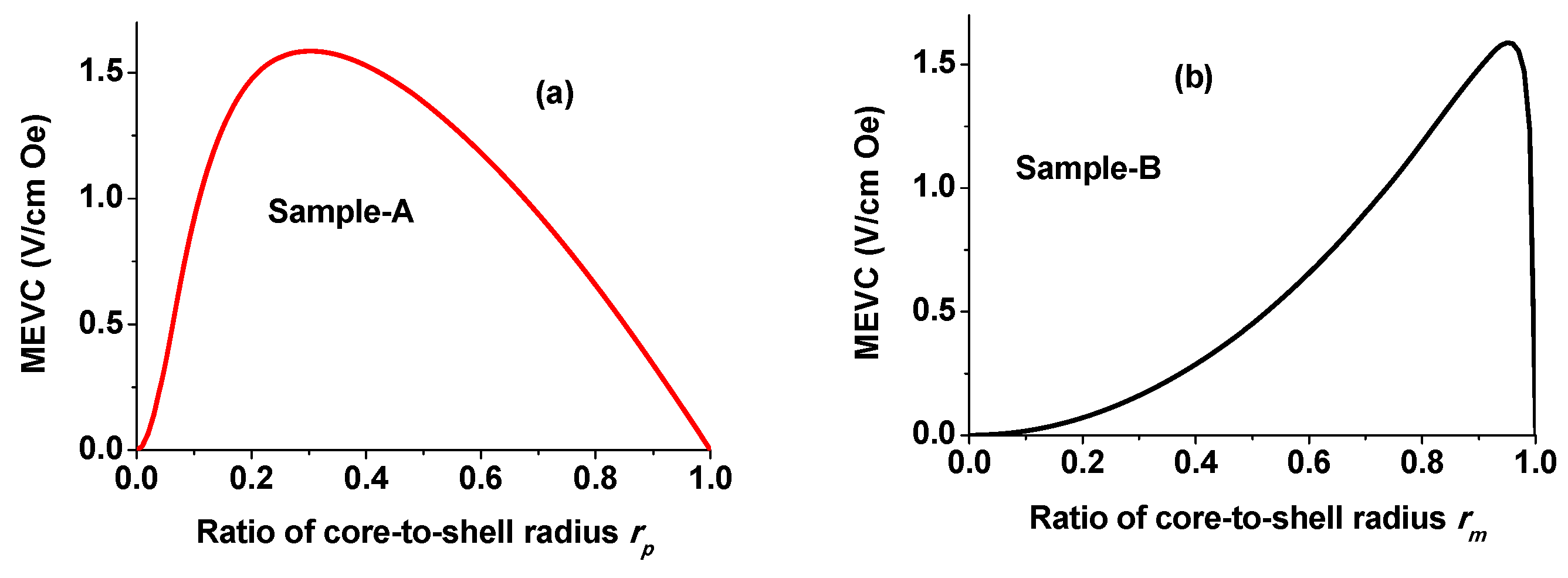
The theories developed are for the direct ME effect on a fiber with a length that is much greater than its radius. It is assumed that the fiber is subjected to a static magnetic field H and an AC magnetic field δH, both along the length of the fiber (direction 3). The resulting piezomagnetic deformation in the ferrite when transferred to the ferroelectric phase will produce an induced electric field δE. Figure 1 shows the estimated MEVC = δE/δH as a function of the ratio of the radius of the core to the radius of the fiber [41]. Figure 1a is for a fiber with a BTO core and an NFO shell (sample A). As rp = core radius/shell radius increases from zero (i.e., in the absence of a BTO core), the MEVC increases from zero, is expected to reach a maximum value of 1.6 V/cm Oe for rp = 0.33, and then decreases to zero for rp = 1 when the fiber is BTO and does not contain a ferrite shell. Similar estimates for a fiber with an NFO core and a BTO shell (sample B) are shown in Figure 1b. A maximum MEVC~1.6 V/cm Oe is expected for this case when the radius ratio is 0.95. The dependence of MEVC in Figure 1 is significantly different from similar estimates for bulk or 2-2 laminate (layered) composites in which a maximum MEVC is predicted for composites with an equal volume fraction or thickness of the two phases [8].
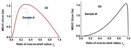
Figure 1.
Estimated maximum value of ME voltage coefficient (MEVC) as a function of (a) the ratio of the radius of BTO core and NFO shell and (b) radius of NFO core and BTO shell. [41].
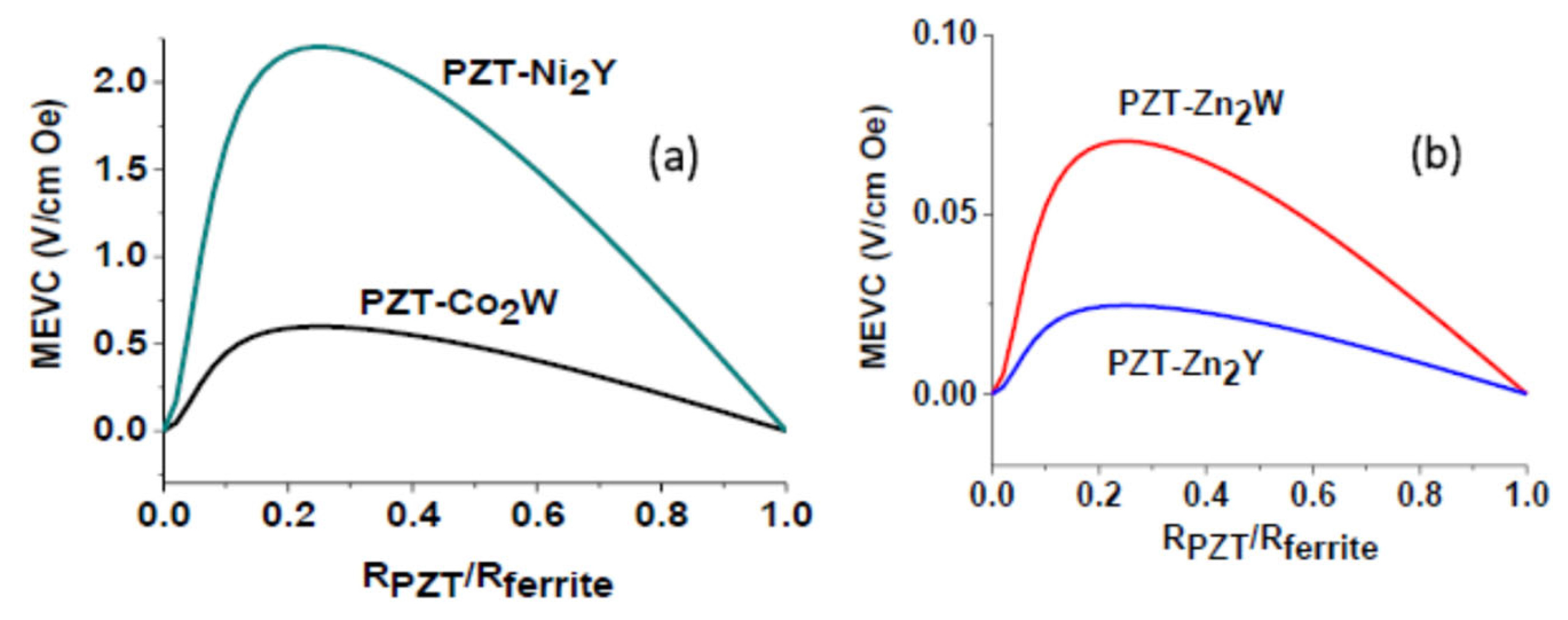
Figure 2 shows the results of similar modeling for fibers with W- or Y-type hexagonal ferrites and PZT [47]. The material parameters in Table 1 are used for theoretical values of MEVC as a function of the ratio of the PZT core to the ferrite shell. MEVC is expected to be the largest for fibers with Ni2Y and the smallest for fibers withZn2Y. A maximum MEVC is expected when the ratio of the core-to-shell radius is ≈0.3. Fibers with Zn2W or Zn2Y have much lower MEVC compared with their counterparts due to a weak magnetostriction and q-value. Estimates for the hexaferrite core–PZT shell are provided in [47].
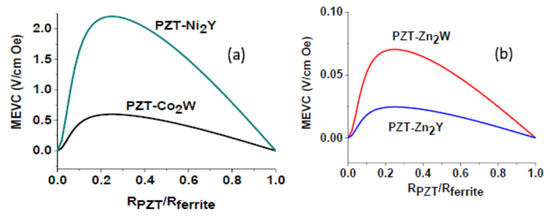
Figure 2.
Estimated maximum value of MEVC as a function of the ratio of the radius of PZT core and (a) Ni2Y- or Co2W-type hexagonal ferrite shell and (b) Zn2W- or Zn2Y-type hexagonal ferrite shell [47].
The results in Figure 1 and Figure 2 are for a single isolated fiber. A very significant reduction in the measured values of MEVC is expected, in particular, for assemblies of the fibers due to several assumptions in the theory. The theory does not consider the following: (i) The results in Figure 1 and Figure 2 are for material parameters measured in polycrystalline ferroelectric and magnetic phases. For nanomaterials, however, one anticipates much smaller ferroic order parameters. (ii) The theory did not take into account magnetic or electric dipole–dipole interactions. Interactions between ferrite cores or shells will lead to a demagnetizing field that will result in a reduction in the strengths of both DC and AC magnetic fields and a decrease in MEVC. (iii) Porosity or airgaps in the fiber assemblies will also have a similar effect on MEVC. Influences of these factors are considered in detail later in the discussion part (Section 6).
3. Nanofiber Synthesis
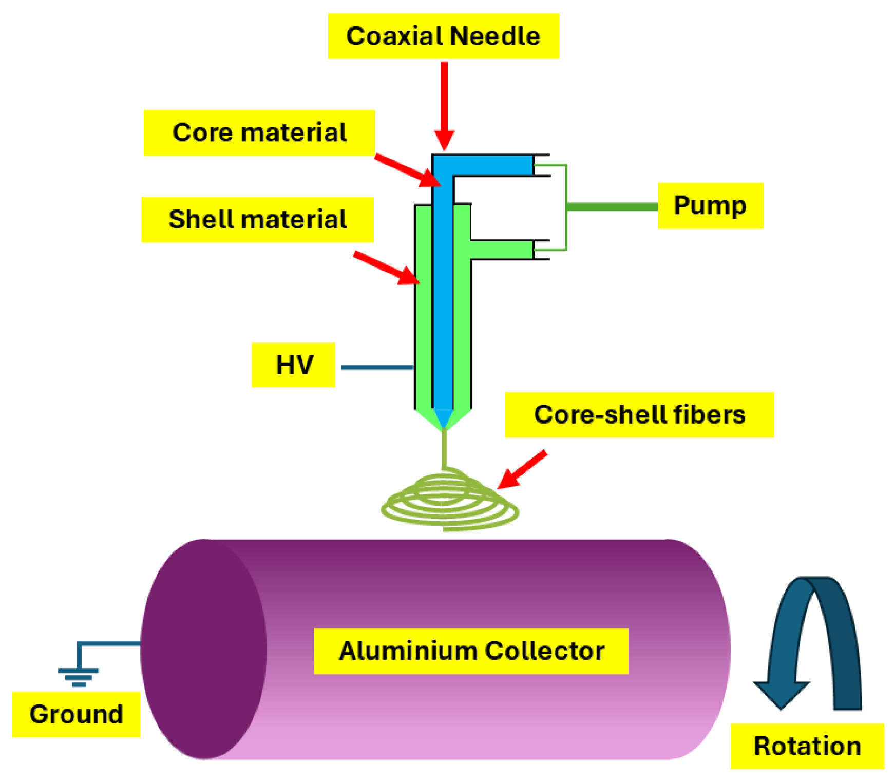
There are several techniques, including sol–gel routes [48,49], electrodeposition [50], template assisted synthesis [51], and electrospinning [39,40,41,42,43], that are utilized for the synthesis of coaxial fibers. Electrospinning has several advantages over other competing techniques for the synthesis of core shell fibers, e.g., (i) it is a low-cost synthesis technique compared with lithography or template-assisted processes; (ii) fibers of uniform core and shell structures free of any defects can be prepared; (iii) the technique can be easily scaled up for the large-scale synthesis of nano- and microfibers. In this review, we focus on fibers made by electrospinning. The synthesis in general involves the following steps [52,53]: The first step in the process involves the preparation of the sols for core and shell materials separately with precursors that are soluble in water/alcohol or that are liquid themselves. For ferrite fibers, one generally uses metal acetates or nitrates for the sol. A polymer, usually polyvinylpyrrolidone (PVP), is added to the solutions to make the sol viscous. Second, the sols are loaded onto two separate syringes and dispensed with a syringe pump, as in the setup shown schematically in Figure 3. The viscosity of the sols has to be adjusted for optimum pumping rates and to control the fiber dimensions.

Figure 3.
Diagram of electrospinning setup for synthesis of coaxial core–shell nanofibers.
Finally, the sol fed through a dual chamber stainless steel needle is subjected to an electric field of 1.5–2 kV/cm by applying a DC voltage between the needle and a metal drum used to collect the fibers (Figure 3). As the sols exit the needle tip they are electrically charged, and the repulsive Coulomb force leads to the formation of a Tyler cone and eventually to the formation of fibers of the ceramics that are collected on a rotating metal drum. As-spun fibers are dried at room temperature for 24 h and then annealed at a desired temperature in order to complete the formation of ferrites and ferroelectrics [52,53].
4. Spinel Ferrite–Ferroelectric Coaxial Fibers
Studies on fibers with spinel ferrites mainly focus on cobalt ferrite and pure and Zn-substituted nickel ferrite [37,38,39,40,41,42,43,44,54,55,56,57,58,59]. Such spinel ferrite–ferroelectric systems are preferred, since past studies on bulk composites with spinel ferrites and BTO or PZT indicate the absence of any impurities when both phases are co-sintered at high temperatures [4]. Fibers with hexagonal ferrites and PZT or BTO are considered in Section 5.
4.1. Cobalt Ferrite–PZT Core–Shell Nanofibers
CoFe2O4 (CFO) is one of the well-studied spinel ferrites in ME composites due to its large magnetostriction (−110 ppm) and high Curie temperature (520 °C) [60]. Ferroelectric lead zirconate titanate, PbZrxTi1-xO3 (PZT), in particular with a morphotropic phase boundary composition of x = 0.52, has the desired large piezoelectric coefficient (d33 = 200–400 pC/N) and high Curie temperature (386 °C) [61,62]. The combination of these two ferroic phases has attracted significant interest in the fabrication of ME materials with a variety of mechanical connectivities [56,57,63,64,65].
The first reported studies on CFO-PZT fibers were carried out by Xie et al. [56,57]. Sols made with metal nitrates or acetates were used to synthesize the fibers by electrospinning and annealed fibers were characterized in terms of ferroic order parameters by PFM and magnetization measurements [56]. In another study on CFO and PbZrxTi1-xO3 with x = 0.2, annealing of the fibers at high temperatures was reported to result in minor deformations in their shape, as seen in Figure 4a [40]. Structural characterization of annealed fibers by X-ray diffraction showed diffraction peaks corresponding to CFO and PZT and the absence of any impurities (Figure 4b).
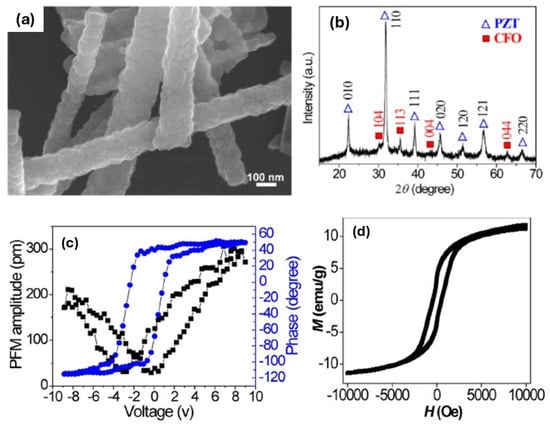
Figure 4.
(a) SEM image of CFO-PZT core–shell fiber after heat treatment. (b) XRD profile of annealed CFO-PZT nanofiber. (c) PFM amplitude and phase angle as a function of applied voltage for a CFO-PZT fiber. (d) Magnetization M vs. static magnetic field H for the fibers [40].
Liu et al. confirmed the ferroelectric nature of the fibers by PFM measurements [40]. The PFM amplitude versus voltage data and the 180° contrast in the phase angle hysteresis loop in Figure 4c are clear evidence of the piezoelectric nature of the fiber rather than it having originated from electrostatic interactions. The estimated piezoelectric coefficient d33 from the PFM data was 30 pm/V. Measurements of d33 by PFM on CFO-PbZr0.52Ti0.48O3 fibers yielded values ranging from 125 to 157 pm/V, depending on the molar fraction of CFO and PZT [56]. Ferromagnetic characterization on the fiber was performed by measuring the magnetization M with a vibrating sample magnetometer. Figure 4d shows the expected M vs. H hysteresis loop at room temperature with a saturation magnetization of 12 emu/g, which is a smaller than expected value for pure CFO since the fiber also contains nonmagnetic PZT.
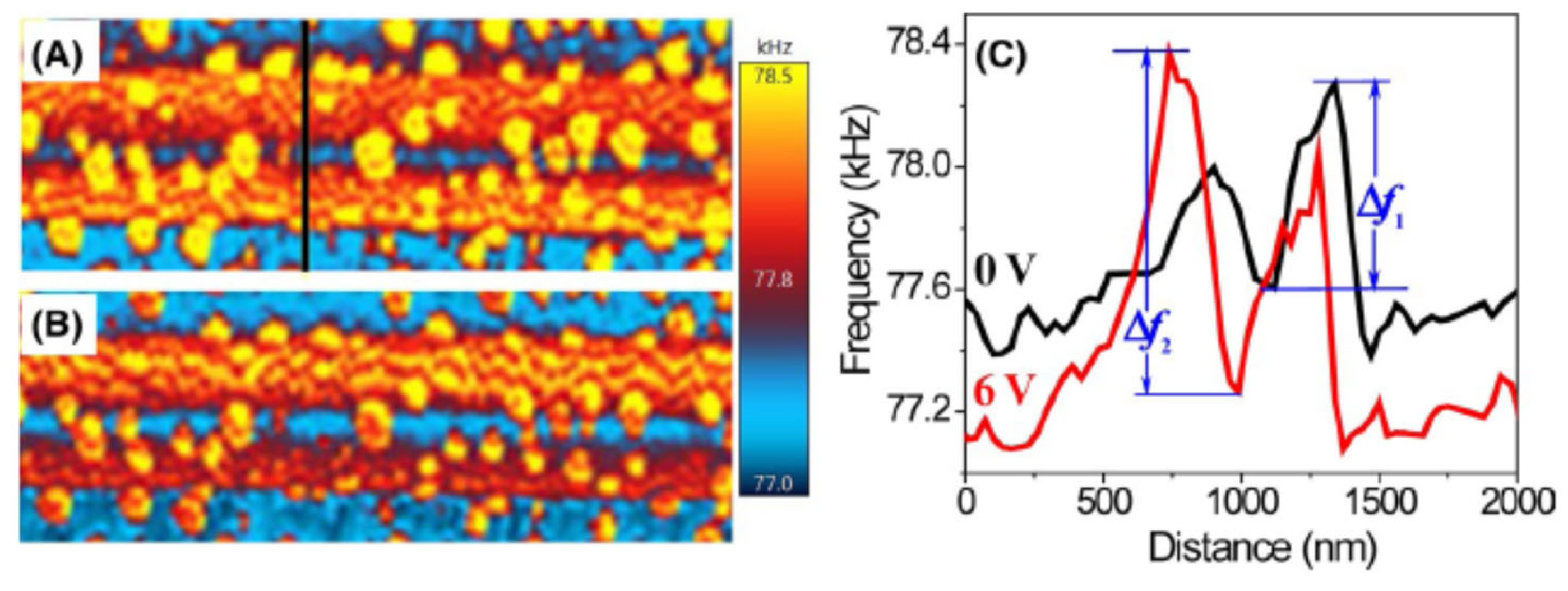
Several investigators have reported on the measurements of ME coupling in individual fibers by scanning probe microscopy. Liu et al. [40] carried out MFM of CFO-PZT under an applied voltage to determine the strength of a converse ME (CME) effect. The magnetic domains were imaged (Figure 5A) first by the MFM mode. Then, the fiber was poled electrically by applying a DC voltage to the tip, operating under the PFM mode. This was followed by MFM to determine any change in the magnetization in CFO due to the piezoelectric strain in PZT (Figure 5B). The procedure could be used to determine the strength of the static converse ME coupling from data on the shifts in MFM frequency maps. The profiles in Figure 5C show significant changes in the frequency shifts, ∆f, before and after applying a poling voltage of 6 V to the fiber, and the shift in turn is proportional to the magnetization of CFO. From these data, the estimated ME susceptibility is 1.2 × 10⁻⁸ s/m [40]. Xie et al., on the other hand, reported MEVC = 29.5 V/cm Oe from PFM studies under a static magnetic field [57]. It is one of highest MEVC reported for a composite of CFO and PZT and is two orders of magnitude higher than values reported for bulk or layered composites of CFO and PZT [4].
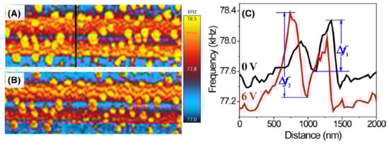
Figure 5.
MFM images of CFO-PZT fiber poled under (A) 0 V and (B) 6 V. (C) Profiles of MFM frequency signals before and after poling of the fiber. The frequency shifts ∆f1 and ∆f2 are proportional to the magnetization of CFO in the fiber [40].
4.2. CoFe2O4-BaTiO3 Core–Shell Nanofibers
Apart from PZT, another well-studied ferroelectric phase in the composites with CFO is BTO with TC = 120 °C and d33 = 260 pC/N [64,66,67]. Shvartsman et al. reported on the preparation of CFO-BTO fibers by coating the ferrite particles with a sol of BTO. Upon high temperature annealing, XRD measurements revealed the fiber formation free of any impurity phases [66]. An ME susceptibility of αC ≈ (2.2 ± 0.1)10−11 s m−1 was determined for the ceramic samples of the fibers by the converse ME effect by PFM under an applied H [66].
Fu et al. prepared coaxial fibers of BTO-CFO by electrospinning [67]. Upon annealing at high temperature, the fibers had a room temperature magnetization of 50 emu/g. They utilized PFM measurements on fibers on a substrate and on free-standing fibers to measure the ME coupling. They determined the piezoelectric coupling coefficient and its variation due to an applied H from the slope of PFM displacement vs. V profiles for clamped and free-standing fibers. The MEVCs estimated from the PFM data were 12 V/cm Oe and 35 V/cm Oe, respectively, for fibers under clamping due to a substrate and free-standing fibers.
4.3. NiFe2O4-PZT Core–Shell Nanofibers
Nickel ferrite (NFO)-based ME composites have been studied extensively in the past [3,4,5,6,7]. Although the saturation magnetostriction λs for NFO is in the order of −30 ppm, which is much smaller than for CFO, the maximum value of the piezomagnetic coupling coefficient q = dλ/dH for NFO is higher than for CFO [4]. Since the low-frequency MEVC is directly proportional to q, one expects a much higher MEVC for NFO- than for CFO-based composites [3,4,5,6,7]. However, there have been very few studies on ME effects on NFO-PZT nanowires or fibers. Liu et al. synthesized core–shell NFO-PZT nanowires by a three-step process involving a sol–gel process to form PZT tubes, followed by electrodeposition of the NiFe alloy to fill the cores of the tubes, and high-temperature annealing to form the wires with an NFO core and a PZT shell [29]. Arrays of the nanowires were characterized in terms of ferroic order parameters.
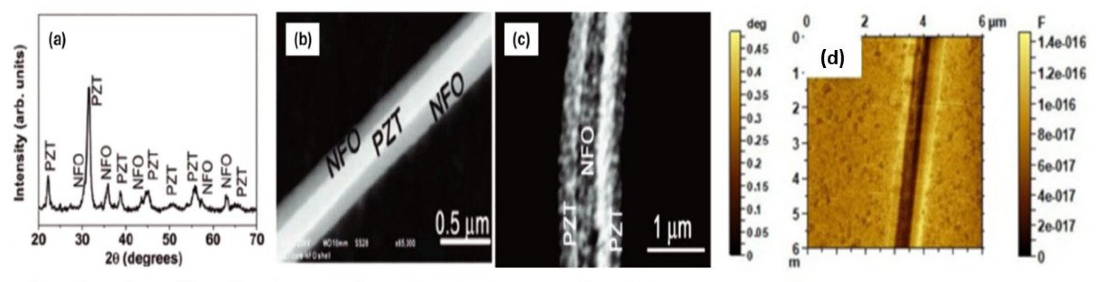
The first studies on the synthesis and ME characterization of NFO-PZT core–shell fibers were reported by Srinivasulu et al. [39]. Fibers with a PZT core–ferrite shell (sample A) or a ferrite core–PZT shell (sample B) were prepared by electrospinning using sols of NFO and PbZr0.52Ti0.48O3. Fibers, upon annealing at 650 °C, had a core diameter in the range 200–450 nm and a shell thickness of 125–175 nm. XRD data, shown in Figure 6a, were indicative of absence of any impurity phases. The compositions of both NFO and PZT were confirmed by energy dispersive X-ray spectroscopy (EDS). SEM images in Figure 6b,c show fibers with uniform core diameters and shell thicknesses and interfaces free of any defects [39]. Further confirmation of the core and shell structure was obtained from scanning microwave microscope (SMM) images at 2–20 GHz [68]. Figure 6d shows an SMM image of capacitance at 5.7 GHz. The core–shell structure for the fiber is well resolved in the SMM image. Magnetization and ferromagnetic resonance (FMR) measurements of the fibers confirmed the ferromagnetic ordering of NFO in the fibers. Ferroelectric polarization P vs. E for the fibers were indicative of P-values that were one to two orders of magnitude smaller than for bulk or thin films of PZT [39].
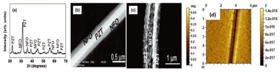
Figure 6.
(a) XRD pattern of NFO-PZT core–shell nanofibers. SEM images of fibers with (b) NFO shell–PZT core and (c) PZT shell–NFO core. [39] (d) Scanning microwave microscope (SMM) image of capacitance at 5.4 GHz for a fiber with an NFO core and a PZT shell [68].
Direct ME effects on NFO-PZT fibers were investigated by (i) P vs. E under H in a disk of the fibers pressed in a static magnetic field and (ii) change in the permittivity measured at 20–22 GHz under H in films of the fibers assembled under a magnetic field [39]. For P vs. E under H, films of the fibers were pressed into a disc in a uniform magnetic field of 3 kOe. Partial alignment of the fibers in the H direction was evident from SEM images, as shown in Figure 7a, for fibers with an NFO core and a PZT shell. Measured P vs. E are shown in Figure 7b for H = 0–7 kOe [39]. The fractional change in the remnant polarization ∆Pr/Pr = [Pr (H)—Pr (0)]/Pr (0) versus H, a measure of DME effects on the fibers, is shown in Figure 7c. A hysteresis showing an increase in Pr with increasing H was followed by a further increase in Pr when H was decreased back to zero. A similar behavior, but with a decrease in Pr under H, was reported for a disc containing fibers of a PZT core and an NFO shell [39].
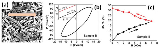
Figure 7.
(a) SEM image showing the alignment of fibers in disc of fibers of sample B pressed in a magnetic field of 3 kOe. The arrow represents the direction of H. (b) P vs. E data for the disc in an applied H up to 7 kOe. (c) Fractional change in the remnant polarization Pr as a function of H for the disc for increasing and decreasing H [39].
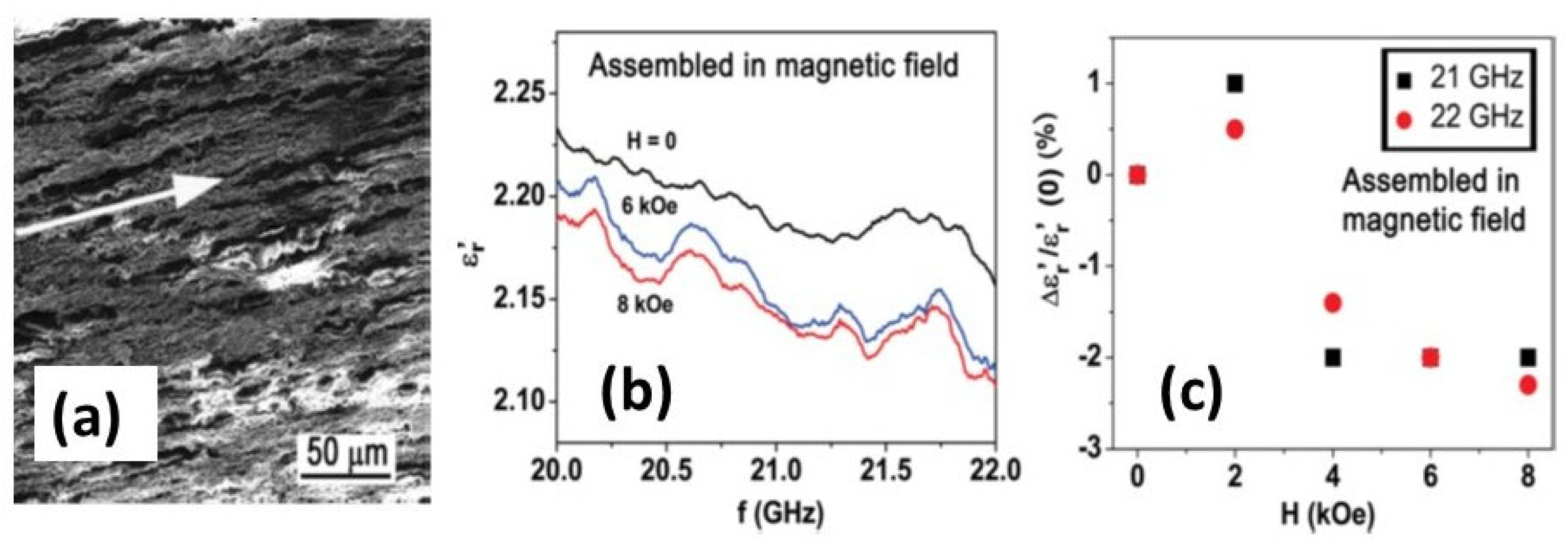
The overall fractional increase in Pr for the NFO-PZT fibers was higher by an order of magnitude or more than reported values for bulk or layered NFO-PZT composites [3,4,5,6,7,11,17]. The strength of DME in NFO-PZT was also measured by the magneto-dielectric effect, i.e., H-induced variation in the real part of relative permittivity εr′ of a film of the composites assembled in a magnetic field gradient produced by a permanent magnet [39]. Figure 8a shows an SEM image of such a film of sample B. Results of the variation of εr′ vs. f for a series of H at 20–22 GHz, well above FMR frequencies for the fibers, are shown in Figure 8b. The procedure for the measurements is described in [39]. The fractional changes in εr′ under H at 21 and 22 GHz are shown in Figure 8c. A decrease in εr′ under H is evident and is much higher than the reported values for single phase multiferroics [1,2].
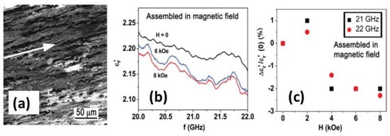
Figure 8.
(a) SEM image of a film of NFO-PZT fibers of sample B assembled on a glass slide in a non-uniform magnetic field gradient. The arrow represents the H direction. (b) Real part of the relative permittivity εr′ vs. f for a series of H for the film of sample B. (c) Fractional change in εr′ vs. H at 21 and 22 GHz for the assembled film of sample B. [39].
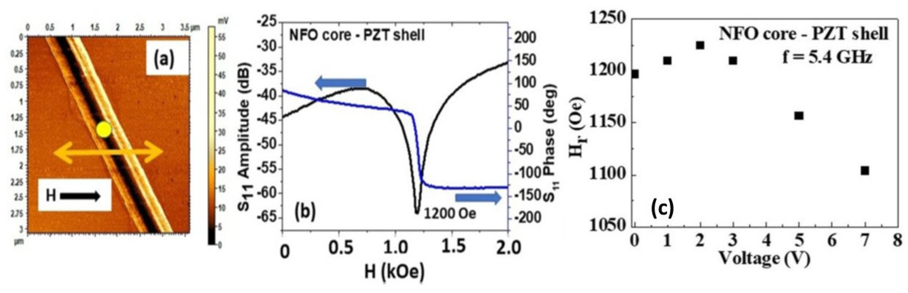
The converse ME (CME) effects on composites were investigated by measuring the magnetization as a function of H under an electric field or the shift in the FMR resonance field or frequency under E [4]. Liu et al. [68] employed an SMM for FMR in an isolated fiber of an NFO core and a PZT shell, as shown in Figure 9a. The amplitude and phase of the reflected microwave power (scattering matrix S11) from the fiber at 5.4 GHz was recorded as the static magnetic field H applied to the fiber was scanned from 0 to 2 kOe. The FMR at the resonance field Hr manifested as a dip in the amplitude and an 1800 phase change in the S11 vs. H profile, as seen in Figure 9b. The FMR profiles were then recorded as a function of applied DC voltage V, and the dependence of Hr on V is shown in Figure 9c. One observes a small increase in Hr as V is increased from 0 to 2 V and is followed by a linear decrease in Hr with increasing V. The voltage-CME coefficient Av = dHr/dV= −24 Oe/V was determined from the slope of the linear regime, as shown in Figure 8c [68], and is either comparable or higher than the reported Av for several ferromagnetic–ferroelectric composites [50].
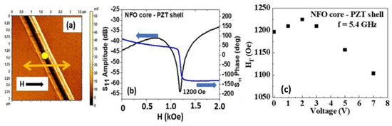
Figure 9.
(a) SMM S11 image of a single fiber of an NFO core–PZT shell. The yellow dot represents the position of the SMM tip during the measurements. (b) S11 amplitude and phase vs. applied magnetic field H at 5.4 GHz showing FMR as a dip in the amplitude and 180o phase shift. (c) The resonance field Hr as a function of applied DC voltage at 5.4 GHz. [68].
4.4. NiFe2O4-BTO Core–Shell Nanofibers
Barium titanate is one of the preferred ferroelectrics for the replacement of lead-based ferroelectrics in ME nanocomposites [69,70] and was used extensively in the early works on bulk ME composites [71,72]. Sreenivasulu et al. reported on the synthesis of BTO-NFO coaxial fibers by electrospinning, and magneto-electric characterization by H-induced ferroelectric polarization, low-frequency MEVC, and high-frequency magneto-dielectric effects [69]. Fibers with a BTO core–ferrite shell and an NFO core–BTO shell were prepared and annealed at 600–700 °C. The core–-shell structure was confirmed with MFM images. Measurements of P vs. E in the discs of the fibers showed p-values as high as 3 μC/cm2 for E = 40 kV/cm. FMR measurements indicated ferromagnetism with a gyromagnetic ratio γ = 3.1 GHz/kOe, and effective magnetization 4πMeff = 480 G.
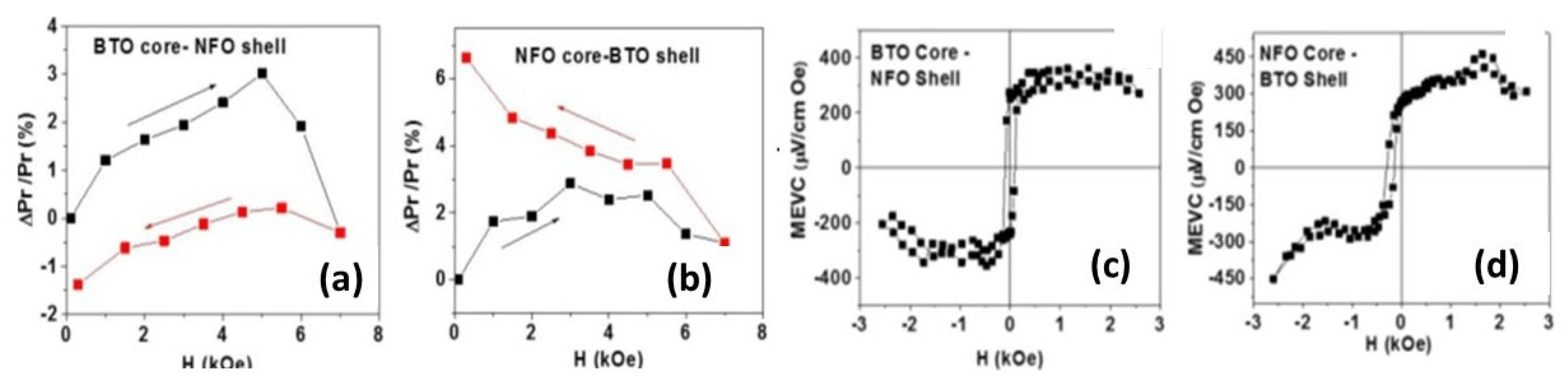
Results of ME coupling measurements in H-assembled discs and thin films of the fibers are shown in Figure 10. Magnetic field-induced variation in Pr was measured on the discs of the fibers pressed in a magnetic field. Figure 10a,b show the fractional change in Pr as a function of H. A hysteresis in (ΔPr/Pr) vs. H and a sign reversal are seen for the disc with fibers of the BTO core–NFO shell and a maximum increase in Pr of 3%. For the disc with fibers of the NFO core–BTO shell, ΔPr/Pr is positive and increases under H to a maximum of 1.5%. Upon decreasing H back to zero, Pr continues to increase to a maximum of 6.5% at H = 0. The results of MEVC versus H measured at 100 Hz in H-assembled films of BTO-NFO fibers are shown in Figure 10c,d. A rapid increase in MEVC to a maximum as H is increased from zero is followed by a decrease in its value for H > 2 kOe. An 180° phase shift in ME voltage upon reversal of H direction and a hysteresis in MEVC vs. H are evident, as shown in Figure 10. The film with fibers of the NFO core–BTO shell shows a large zero-bias MEVC. Although the H-induced polarization and results of the magneto-dielectric effects [69] provide clear evidence for strong ME coupling in the fibers, the overall magnitude of MEVC in Figure 10 are orders of magnitude smaller than for bulk or layered composites [3,4,5,6,7,71,72], and the possible causes are discussed in Section 6.
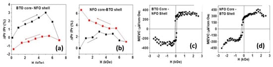
Figure 10.
The fractional change in the remnant polarization as a function of static field H for discs of fibers of (a) BTO core–NFO shell and (b) NFO core–BTO shell. Low-frequency MEVC vs. H for films of fibers of (c) BTO core–NFO shell NFs and (d) NFO core–-BTO shell [69].
4.5. Nickel Zinc Ferrite–PZT Core–Shell Fibers
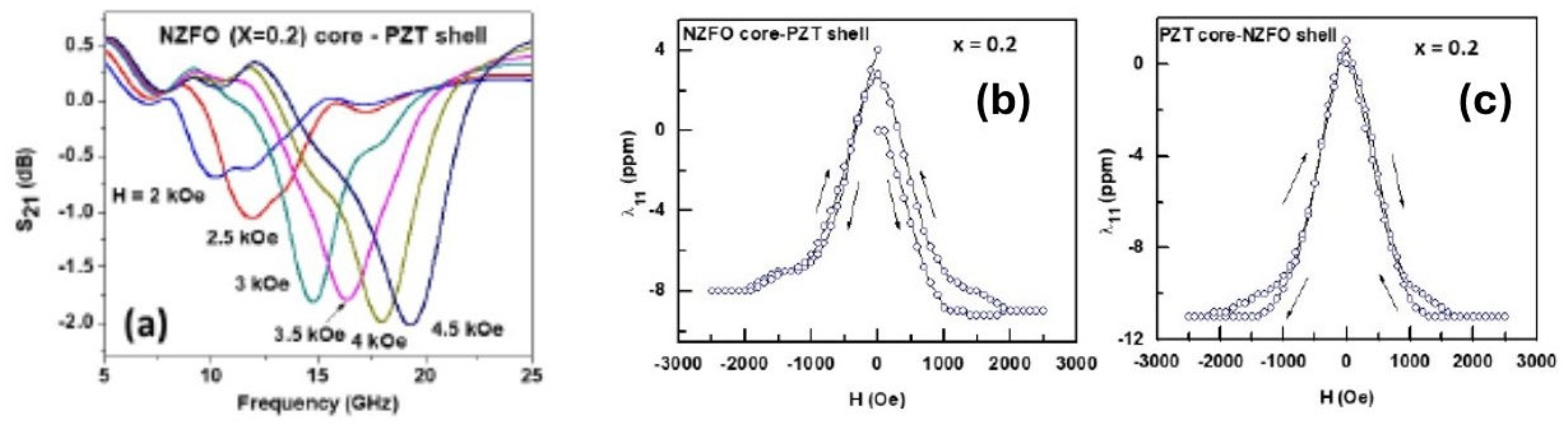
Zinc-substituted nickel ferrite, Ni1-x Znx Fe2O4 (NZFO), and ferroelectrics are well-studied composite systems in the form of thin films, thick films, nanopillars, etc., due to their large magnetostriction and piezomagnetic coupling coefficients [3,65,73,74]. Studies on coaxial fibers of NZFO-PZT were reported very recently by Ge et.al. [59]. Core–shell fibers of NZFO (x = 0.1–0.5)—PZT, prepared by electrospinning with a diameter in the range 1–3 μm and annealed at 700–900 °C, were free of impurity phases and had uniform core and shell structures, as seen in electron and scanning probe microscopy images [59]. Ferromagnetic ordering of NZFO was confirmed by FMR and by magnetization measurements. A gyromagnetic ratio γ = 2.7–3.1 GHz/kOe and effective magnetization 4πMeff = 0.9–2.9 kG were estimated from FMR profiles, as shown in Figure 11a. The saturation magnetizations for the fibers were in the range M = 5–24 emu/g. The magnetostriction λ11 was measured along the H direction, with a strain gage on the discs of the fibers. Profiles of λ11 vs. H, as in Figure 11b,c for NZFO (x = 0.2)-PZT showed hysteresis and the saturation values of λ11 varied from −5 ppm to −11 ppm, depending on the x-values [59].
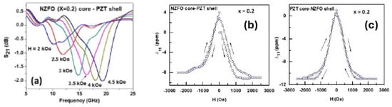
Figure 11.
(a) Scattering matrix parameter S21 vs. frequency f for showing FMR for a series of in-plane static magnetic field H for a rectangular sample of fibers of NZFO (x = 0.2)-PZT. Magnetostriction λ11 measured along H-direction vs. H for a disc with fibers of (b) Ni0.8Zn0.2Fe2O4 core–PZT shell and (c) PZT core–Ni0.8Zn0.2Fe2O4 shell [59].
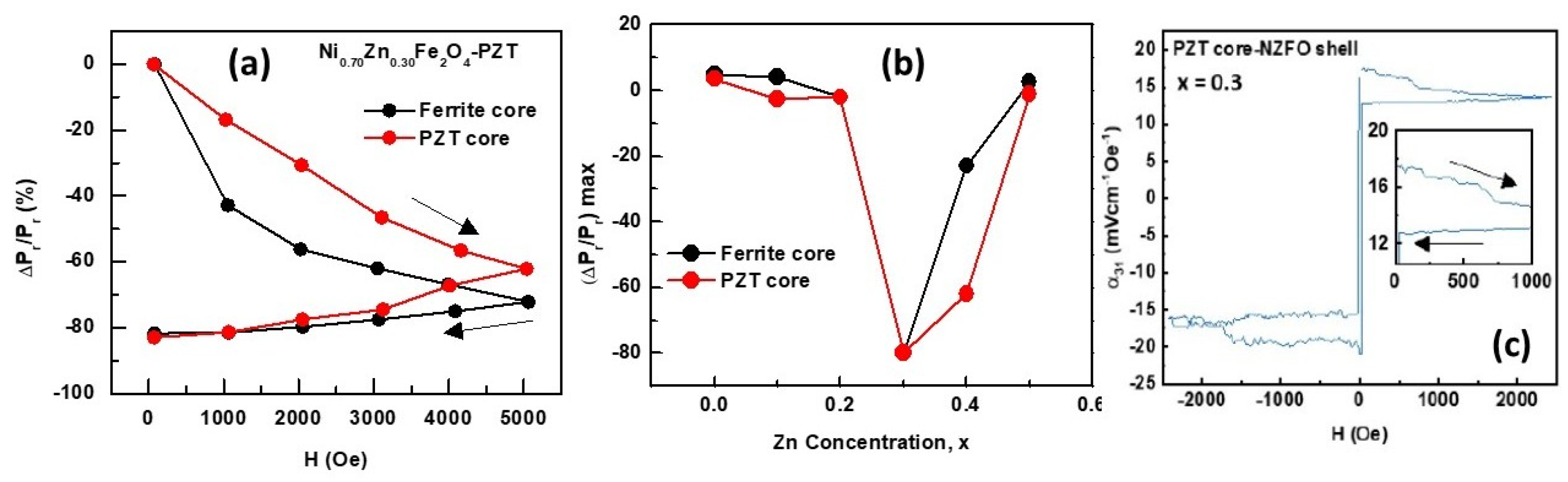
The strength of ME coupling in the composites was measured by H-induced variation in Pr and low-frequency MEVC. Estimated ∆Pr/Pr from P vs. E under H, as in Figure 12a,b, in discs of the fibers of NZFO (x = 0.3)-PZT, showed evidence of a giant ME coupling [59]. A “memory effect” was seen in the data, characterized by an increase in the magnitude of ∆Pr/Pr to 80% when H was increased from 0 to 5 kOe and this value was retained when H was decreased back to zero. A similar behavior was evident for samples with either a ferrite core or a PZT core. Low-frequency MEVC measured in fiber discs showed a rapid increase in H, as shown in Figure 12c, and the maximum MEVC values ranged from 6 to 35 mV/cm Oe and were an order of magnitude smaller than reported values for thick film NZFO-PZT [65].
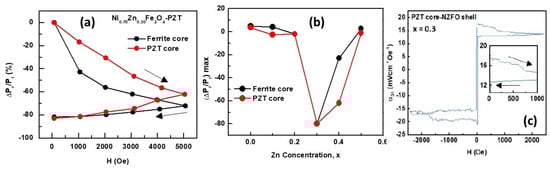
Figure 12.
(a) Fractional variation in Pr vs. H for Ni0.7Zn0.3Fe2O4-PZT coaxial fibers with ferrite core and PZT core. (b) Variation of maximum value of ∆Pr/Pr with Zn concentration for fibers of Ni1-xZnxFe2O4 (x = 0–0.5)-PZT. (c) MEVC vs. H in a disc of fibers of NZFO (x = 0.3) shell–PZT core [59].
5. Hexagonal Ferrite and Ferroelectric Core–Shell Fibers
Ferrimagnets with hexagonal crystal structures with desirable magnetic parameters are of importance for use in ME composites. Hexaferrites, depending on the arrangement of spinel and hexagonal blocks, are classified into M-, W-, Y-, U-types, etc. Most of them have a very high uniaxial or planar magneto-crystalline anisotropy field, Ha [46]. M-type ferrites such as barium (BaM) and strontium (SrM) hexaferrites, for example, have uniaxial anisotropy fields of 18 to 20 kOe. Although composites with hexaferrites have weak direct ME interactions due to smaller magnetostriction compared with CFO or NFO, they are attractive for use in ME composites due to the high Ha values that could give rise to a strong ME coupling in the absence of an external bias magnetic field. Such zero-bias ME coupling is of importance for composite-based sensors and energy harvesters [75]. This section deals with ME coupling in composites with ferrimagnetic M-, Y-, or W-type hexaferrites and PZT or BTO.
5.1. M-Type Hexaferrite-Based Core–Shell Nanofibers
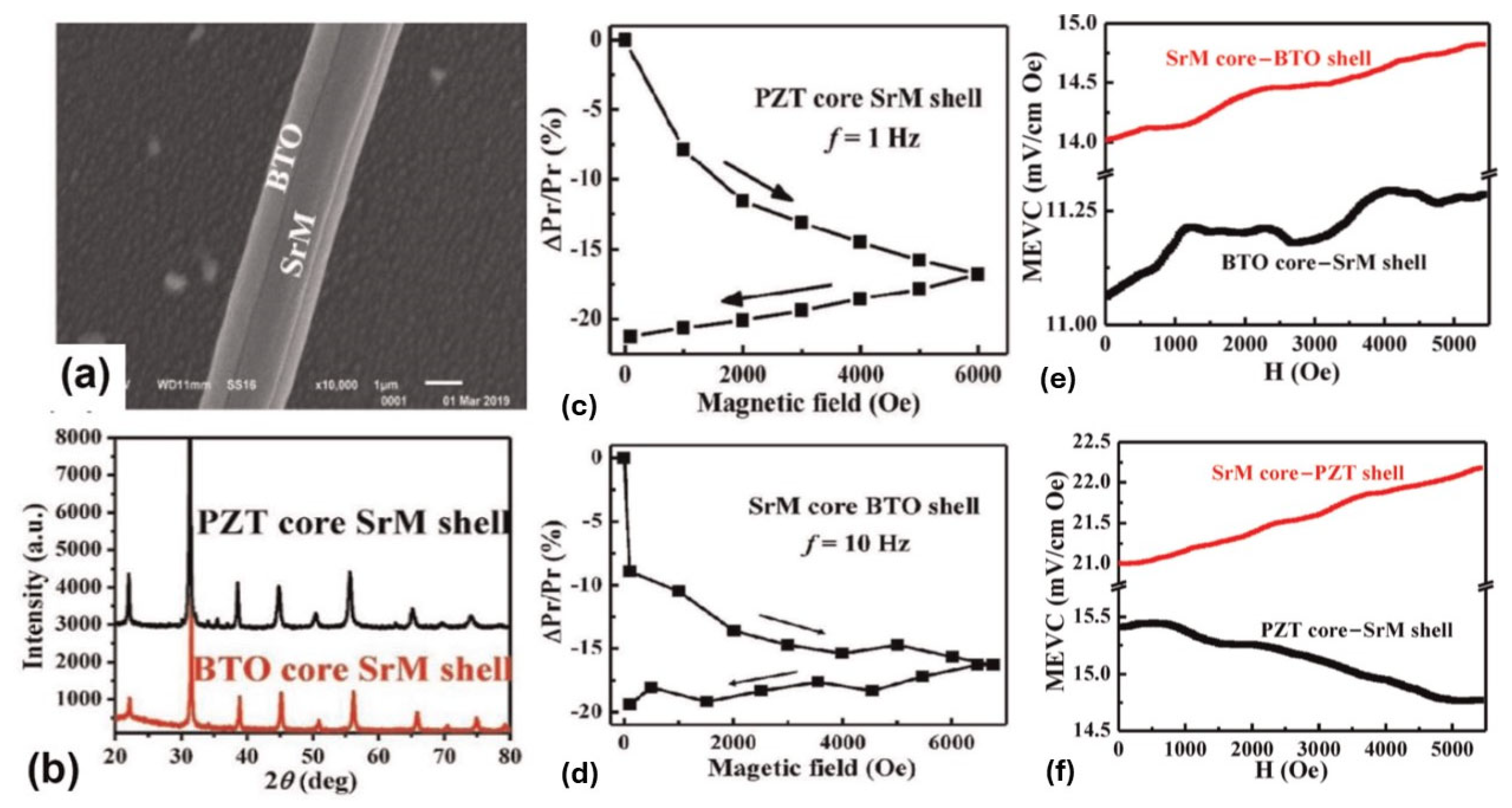
Liu et.al. reported on the synthesis of coaxial fibers of M-type strontium hexagonal ferrite, SrFe12O19, (SrM), and BTO or PZT [76]. SrM is a good candidate material amongst the M-type hexaferrites due to a large Ha of around 20 kOe [46]. The electrospinning procedure was similar to the ones described earlier for spinel ferrites and ferroelectrics. Fibers with either a ferrite core or a ferroelectric core were made and annealed at 700–1000 °C [76]. An SEM micrograph for the fibers clearly revealed the core–shell structure, as shown in Figure 13a, for a SrM core–BTO shell fiber. XRD data, as shown in Figure 13b, showed strong diffraction peaks for the piezoelectric phase, i.e., PZT/BTO, and relatively weaker peaks for SrM.
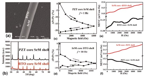
Figure 13.
(a) SEM image of annealed fiber of SrM core–BTO shell. (b) XRD patterns of PZT-SrM and BTO-SrM fibers. Fractional change ∆Pr/Pr in discs of fibers of (c) PZT core–SrM shell and (d) SrM core–BTO shell. MEVC for 3D films consisting of fibers of (e) SrM core–PZT shell and (f) SrM core–BTO shell [76].
The nature of ME coupling was studied by H-induced P on a disc of the fibers annealed at 900 °C [77]. In addition, low-frequency MEVC was measured on 2D and 3D films of the fibers assembled in a magnetic field. The fractional change in Pr for PZT core–SrM shell and SrM core–BTO shell fibers are shown in Figure 13c,d [76]. The data for PZT-SrM showed a decrease in Pr under H and its magnitude increased under H to −17% for H = 6 kOe. Upon decreasing H, Pr continued to decrease further to −22% at H = 0. A similar behavior for H-induced Pr at the same magnitude is evident in Figure 13d for fibers of SrM-BTO. Data on MEVC measured at 100 Hz in 3D films of SrM-BTO and SrM-PZT are shown in Figure 13e,f. A very large zero-bias MEVC, at H = 0, is seen in the data and is due to a large “built-in” bias field provided by the magneto-crystalline anisotropy for SrM. The MEVC increased with increasing H, except for the fibers with a PZT core–SrM shell, which showed a decrease under H. The overall magnitude of the MEVC was comparable to results reported for layered composites of single crystal SrM and PZT [78].
5.2. Y-Type and W-Type Hexaferrite-Based Core–Shell Nanofibers
Y- and W-type hexaferrite have more complex structures relative to M-type ferrites, but the hexagonal symmetry remains [46]. Liu et al. [79] studied coaxial fibers of Y- and W-type ferrites and PZT or BTO. Y-types with the composition Ba2Ni2Fe12O22 (Ni2Y) and Ba2Zn2Fe12O22 (Zn2Y) with in-plane anisotropy fields Ha = 14 kOe and 9 kOe, respectively, were chosen. Both had much lower Curie temperatures compared with SrM [46]. Their choices for W-type ferrites were BaCo2Fe16O27 (Co2W) and BaZn2Fe16O27 (Zn2W) with uniaxial anisotropy fields Ha = 21 kOe and 12.5 kOe, respectively. Individual fibers of Y- and W-type hexaferrites and coaxial fibers with PZT or BTO were prepared, and their direct ME effects were systematically studied. Individual fibers of Y-type and W-type ferrites made by electrospinning were characterized in terms of crystal structure and magnetic parameters, and the magnetostriction of the fibers was smaller than the vales of the bulk samples [47,79]. The saturation magnetostriction λs measured on the annealed disks of the fibers was −10 ppm for both Zn2W and Co2W, whereas it was −13 ppm for Ni2Y and −2.5 ppm for Zn2Y. Several groups also previously reported on the synthesis and magnetic characterization of pure hexaferrite fibers [80,81,82].
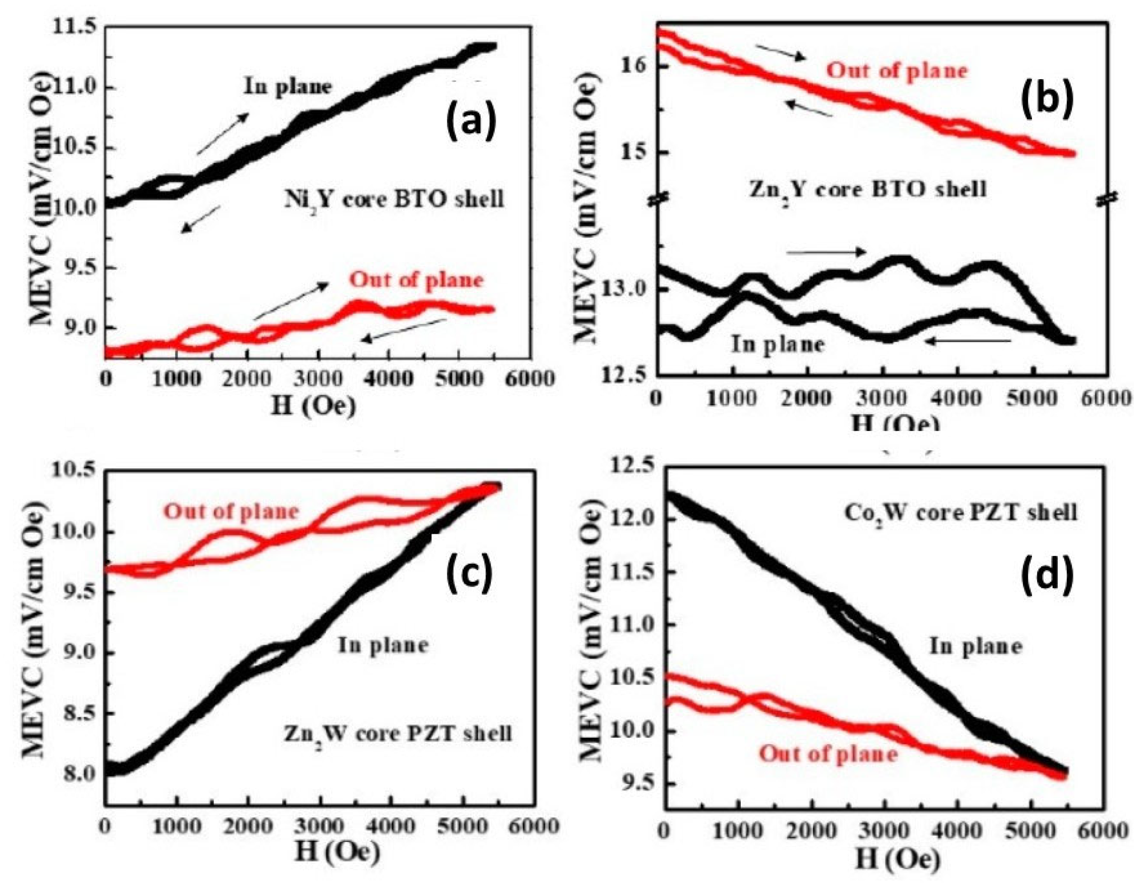
Core–shell fibers of Y- and W-type ferrites and PZT or BTO were annealed at 900–1000 °C and SMM images showed well-formed and defect-free core–shell structures in all of the fiber systems [79]. The saturation magnetization at room temperature for the fibers ranged from a minimum of 2.5 emu/g for Zn2W-BTO to a maximum of 8 emu/g for Co2W-PZT. The maximum polarization obtained from P vs. E measurements on the discs of the fibers were in the range 1–2.5 μC/cm2. Both 2D and 3D films of the annealed fibers were assembled in a static magnetic field for measurements of MEVC vs. H. Representative data from [79] for 3D films for both DC and AC magnetic fields parallel or perpendicular to the film plane are shown in Figure 14 for Ni2Y-BTO, Zn2Y-BTO, Zn2Y-BTO, Zn2W-PZT, and Co2W-PZT.
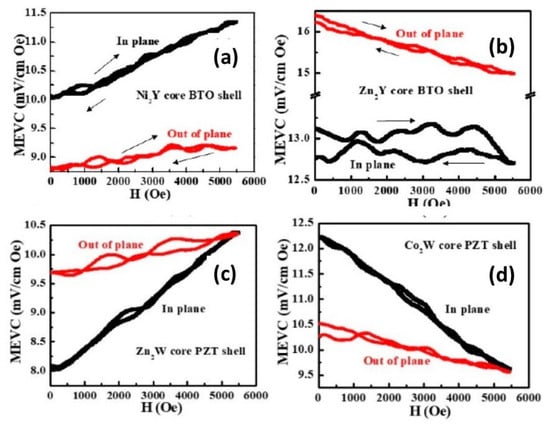
Figure 14.
MEVC vs. H data for 3D films of fibers of (a) Ni2Y core-PZT, (b) Zn2Y core-PZT, (c) Zn2W core–PZT shell, and (d) Co2W core–PZT shell. Results are for magnetic fields parallel or perpendicular to the film plane [79].
The data in Figure 14a,b for films with Y-type ferrite and BTO show a large zero-bias MEVC potentially due to a built-in field arising from the magneto-crystalline anisotropy field. For films with Ni2Y, MEVC is higher for in-plane fields than for out-of-plane fields and it increases under H for both field orientations and there is no hysteresis in MEVC vs. H. For the films with Zn2Y, the MEVC is higher than for Ni2Y, although the magnetostriction for Zn2Y was measured to be much smaller than for Ni2Y [79]. Since MEVC is directly proportional to the piezomagnetic coefficient q = dλ/dH, one may infer from the data in Figure 14 that q for fibers with Zn2Y is higher than for Ni2Y. MEVC for films with fibers of Zn2W and Co2W with PZT are shown in Figure 14c,d. Zero-bias ME effects are evident for both films and MEVC increases under H for the film with Zn2W whereas it decreases under H for films with Co2W. It is clear from the zero-bias MEVC values in Figure 14 that a large magneto-crystalline anisotropy in the ferrite eliminates the need for an external source of bias magnetic field such as an electromagnet or a solenoid.
6. Discussion
It is clear from the discussion so far that the somewhat very limited efforts on ME composites with core–shell nano- and microfibers of ferromagnetic and ferroelectric phases have been primarily on oxides of ferrimagnets and ferroelectrics, since it is rather easy to synthesize fibers free of chemical and structural impurities by electrospinning. There were many reports on fibers with spinel ferrites and ferroelectrics, whereas very few studies focused on hexagonal ferrites and PZT/BTO. Early studies were limited to structural, magnetic, and ferroelectric characterization of the fibers and were lacking any measurements on the nature of ME interactions. Initial reports on ME interactions in core–shell fibers were on CFO-PZT and CFO-BTO and utilized SPM techniques for ME measurements. Piezo force microscopy studies under H were employed to estimate the strength of DME in single fibers [56,57,64,65,66,67]. An ME susceptibility of 1.2 × 10⁻⁸ s/m was measured by a combination of PFM and MFM in CFO-PZT fibers [40]. Reported values of MEVC varied from 29.5 V/cm Oe for CFO-PZT [57] to 35 V/cm Oe for CFO-BTO [67].
Another spinel ferrite-based fiber system studied in the past was NFO-PZT/BTO. Even though XRD data did not reveal any impurity phases and SEM and SPM images showed defect-free fibers, both the magnetization and ferroelectric polarization were reported to be much smaller than for bulk materials [39,69]. Although DME studies by PFM on single fiber are yet to be reported, converse ME effects by FMR were carried out on NFO-PZT using an SMM, and a voltage-CME coefficient of Av = −24 Oe/V was reported [68]. Low-frequency MEVC results were reported for 2D films of the fibers of both NFO-PZT and NFO-BTO and were orders of magnitude smaller than for bulk or thick-layered composites [39,69]. A much higher MEVC, however, was measured in 3D films of the fiber composites. Similar studies on NZFO-PZT coaxial fibers also reported low MEVC values for fiber films [59].
Films of fibers of hexagonal ferrites and PZT/BTO showed a higher MEVC than their spinal ferrite/ferroelectric counterparts [76,79]. The most significant observation in these hexagonal ferrite-based fiber systems was the large zero-bias MEVC due to a built-in bias field provided by the very high magneto-crystalline anisotropy in the ferrites. Hexaferrite/ferroelectric fibers and fiber assemblies with high zero-bias ME effects have the potential for use in both AC and DC magnetic field sensors and in energy harvesting applications since they eliminate the need for a bias magnetic field.
Next, we compared the MEVC for single core–shell fibers in films and discs of fiber samples, with reported values in Table 2 for composites of various mechanical connectivity including bulk (0-3) and layered (2-2) samples [83,84,85,86,87,88,89,90,91,92,93,94]. It is clear from Table 2 that films of core–shell fibers had the lowest MEVC, whereas measurements on individual coaxial fiber had values comparable to bulk and layered composites. It is also noteworthy that the MEVC measured on individual fibers was in fact higher than the theoretical estimates in Figure 1 and Figure 2.
Table 2.
MEVC for ferrite/ferroelectric composites with various mechanical connectivities [83,84,85,86,87,88,89,90,91,92,93,94,95].
The relatively small MEVC for films of the fibers compared with theoretical estimates and values for individual fibers could be attributed to the effects of porosity and dipole–dipole interactions in the fiber films. As discussed in the theory section, the model was only valid for isolated fibers. It is essential to consider the effects of (i) both magnetic and electric dipole–dipole interactions between the cores and shells of ferrites and ferroelectrics and (ii) the porosity (or fiber discontinuity) in films. Magnetic dipole–dipole interactions, in particular, between ferrite cores or shells will give rise to demagnetizing effects and reductions in the magnitudes of applied AC and DC magnetic fields and a reduction in MEVC [47]. In fibers with a ferrite core, one anticipates an increase in the dipole–dipole interaction when the thickness of the ferroelectric shell decreases, leading to a further reduction in MEVC [41,47].
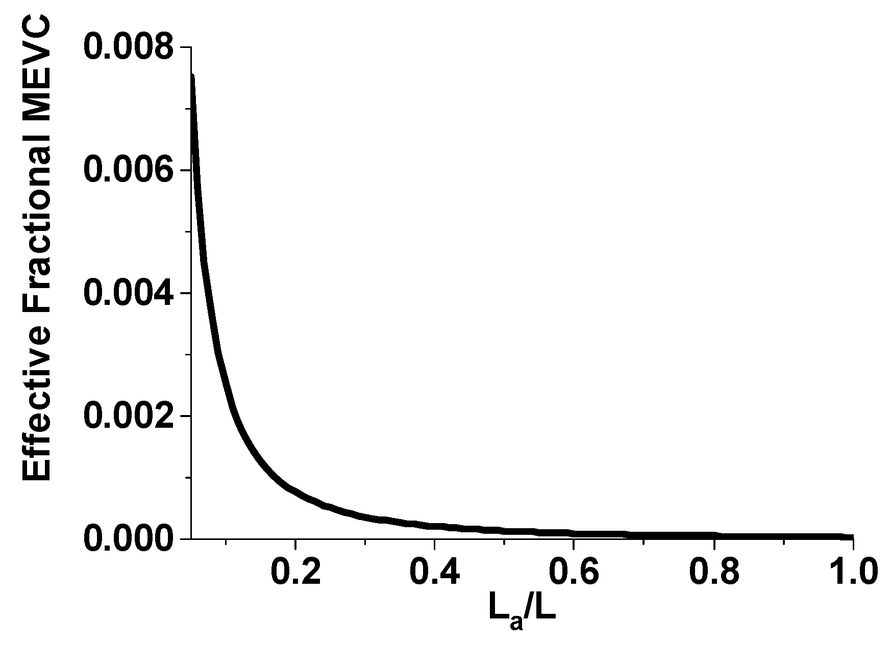
Another source of reduction in MEVC in films is the fiber discontinuity (porosity). This can be taken into account by assuming an air inclusion along the fiber axis that will result in a demagnetizing effect and a reduction in the internal magnetic field and a decrease in ME coupling strength. Assuming an air gap of length La in a fiber of length L, one can estimate the resulting reduction in MEVC. Figure 15 shows the estimated effective fractional MEVC vs. La/L for fibers of the NFO core–BTO shell [41]. A very large reduction in MEVC due to fiber discontinuity is evident from Figure 15. An air gap of 17%, for example, will result in three orders of magnitude reduction in MEVC. Thus, the weakening of the ME coupling strength observed in 2D- and 3D-assembled films of fibers could be primarily due to an air gap (or porosity) in the film.
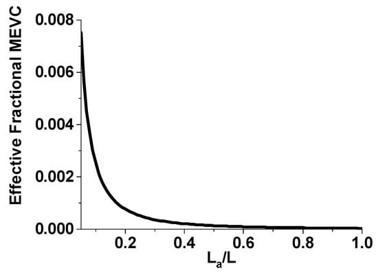
Figure 15.
Effective fractional MEVC as a function of La/L for an assembled film of fibers of sample A. La is the air gap in a fiber of length L [41].
Although MEVC measurements in the assembled film indicated a weak coupling, a strong or even a “giant ME effect” was evident from H-induced polarization measurements on the discs of the fibers of NFO and NZFO and PZT or BTO, with a fractional change in Pr in NZFO-PZT as high as −80% [59,68,69]. A similar strong DME was evident from ferroelectric polarization under H in discs of fibers of M-, Y-, or W-type hexagonal ferrites and PZT or BTO. Results of similar studies on bulk or layered composites are lacking regarding any meaningful comparison with results for coaxial fiber samples.
Finally, in addition to coaxial ferrite/ferroelectric fibers, there have been several reports in recent years on ME effects on ferrite/ferroelectric core–shell wires, Janus-type fibers, and ferrite fibers embedded in ferroelectric thin films. A template-assisted synthesis of CFO-BTO nanowires was utilized to control the magnetic parameters, in particular the anisotropy of CFO, and the ME coupling strength was probed by measuring the variations in the magnetic properties before and after thermal depolarization of the composite [96]. In the Janus nanofiber, in which half the fiber contains CFO and the remaining half BTO, the ME coupling was studied by second harmonic generation polarimetry under an applied magnetic field [97]. A ferroelectric phase of particular interest for use in ME nanocomposites is polyvinylidene fluoride (PVDF), which is a fluoropolymer. It is corrosion resistant and is ideal for synthesizing flexible ME composite structures. There have been recent reports on the synthesis and characterization of fiber mats and thin-film composites of PVDF and spinel or hexagonal ferrites [70,98,99]. Fiber mats of PVDF with nanoparticles of CFO were investigated in terms of the strength of ME coupling strength by H-induced polarization and the maximum polarization was found to decrease by as much as 10% [97]. In another study, ME coupling was determined by H-induced variation in Pr in films of PVDF-based ferroelectric containing SrM fibers [99]. Fractional variation in Pr ranged from 4% to 9%, depending on the amount of SrM fibers in the films.
7. Follow-Up Research
Future efforts on coaxial fibers of ferrites and ferroelectrics need to focus on studies aimed at the following factors: (i) ME measurements to date on single fibers are rather indirect, utilizing PFM under an applied H or MFM under E in order to come up with an estimate of the variation in ferroic order parameters and ME coefficients. Available data obtained from SPM measurements of MEVC and ME susceptibility on isolated fibers of CFO-BTO and CFO-PZT indicate very strong coupling with values comparable to or exceeding the theoretical estimates. Although direct measurements of MEVC involving the application of AC and DC magnetic fields to a single fiber and measuring the resulting induced voltage may be challenging, such measurements are essential for an understanding of ME coupling in coaxial fibers. (ii) Studies on fibers with Zn-substituted CFO are yet to be reported. Even though CFO has large magnetostriction, the piezomagnetic coupling coefficient q is rather small. One could enhance q-values in CFO with Zn-substitution. Thus, fibers of CZFO-PZT/BTO are expected to show strong ME coupling. (iii) The MEVC very much depends on the volume fraction of the ferrites and ferroelectrics in the fibers. There is a wide distribution in the core radius and the shell thickness in fibers prepared by electrospinning. Studies relating the fiber dimensions to ME coupling are essential. (iv) Modeling of H-induced ferroelectric polarization is also essential to understand the “giant ME coupling” inferred from measurements on fibers discs. (v) Al-substituted M-type Sr and Ba ferrites have much higher q and magneto-crystalline anisotropy fields than BaM or SrM and are good candidate materials to achieve strong zero-bias ME coupling in fibers with ferroelectrics. (vi) In addition to the fiber composites discussed here, there are several Y- and W-type hexaferrites with high magnetostriction that are good candidates for use in fiber ME composites. (vii) Experiments aimed at enhancing ME coupling on a collection of fibers are essential, since any applications related to sensors or energy harvesting will require fiber assembly.
8. Conclusions
This review article on coaxial fibers of ferrites and ferroelectrics provided a comprehensive overview of the efforts during the past decade. There have been very few reports on this topic so far, even though one can anticipate a strong ME coupling in fibers due to (i) the high surface-area-to-volume ratio compared with bulk or layered composites and (ii) the absence of clamping effects related to the presence of a substrate in thin-film or nanopillar structures. Scanning probe microscopy techniques were utilized for investigations on ME coupling in individual fibers. Films of fibers assembled in a magnetic field or disc of the fibers were used for MEVC and H-induced variations in ferroelectric order parameters. PFM under H and FMR under E on individual fibers with spinel ferrite and PZT revealed strong direct and converse ME effects. Collections of fibers with NFO, NiZn-ferrite, or CFO for the ferromagnetic phase and PZT or BTO for the ferroelectric phase in general were found to show a strong direct ME coupling by measurements of static magnetic field-induced variations in the ferroelectric polarization, whereas low-frequency MEVC values were much smaller than the reported values for bulk or thick-film-layered composites. Three-dimensional films of hexagonal ferrites with M-, Y-, or W-type structures and PZT or BTO were reported to show an MEVC much higher than for spinel ferrite/ferroelectric films but an order of magnitude smaller than for thick-layered composites.
Author Contributions
All the authors contributed equally to the literature survey, collection of relevant contents for the review, and preparation of the manuscript. All authors have read and agreed to the published version of the manuscript.
Funding
The research at Oakland University was supported by grants from the National Science Foundation (ECCS-2415328, ECCS-EAGER-2236879) and the Air Force Research Laboratory. The research at AFRL was supported by a grant from the AFOSR (Award No. FA9550-23RXCOR001).
Conflicts of Interest
The authors declare no conflict of interest.
References
- Fiebig, M.; Lottermoser, T.; Meier, D.; Trassin, M. The evolution of multiferroics. Nat. Rev. Mater. 2016, 1, 16046. [Google Scholar] [CrossRef]
- Spaldin, N.A.; Ramesh, R. Advances in magnetoelectric multiferroics. Nat. Mater. 2019, 18, 203–212. [Google Scholar] [CrossRef]
- Vopson, M.M. Fundamentals of multiferroic materials and their possible applications. Crit. Rev. Solid State Mater. Sci. 2015, 40, 223–250. [Google Scholar] [CrossRef]
- Nan, C.W.; Bichurin, M.I.; Dong, S.; Viehland, D.; Srinivasan, G. Multiferroic magnetoelectric composites: Historical perspective, status, and future directions. J. Appl. Phys. 2008, 103, 031101. [Google Scholar] [CrossRef]
- Ma, J.; Hu, J.; Li, Z.; Nan, C.W. Recent progress in multiferroic magnetoelectric composites: From bulk to thin films. Adv. Mater. 2011, 23, 1062–1087. [Google Scholar] [CrossRef]
- Palneedi, H.; Annapureddy, V.; Priya, S.; Ryu, J. Status and perspectives of multiferroic magnetoelectric composite materials and applications. In Actuators; MDPI: Basel, Switzerland, 2016; Volume 5, p. 9. [Google Scholar]
- Liang, X.; Chen, H.; Sun, N.X. Magnetoelectric materials and devices. APL Mater. 2021, 9, 041114. [Google Scholar] [CrossRef]
- Rado, G.T.; Folen, V.J. Observation of the magnetically induced magnetoelectric effect and evidence for antiferromagnetic domains. Phys. Rev. Lett. 1961, 7, 310. [Google Scholar] [CrossRef]
- Catalan, G.; Scott, J.F. Physics and applications of bismuth ferrite. Adv. Mater. 2009, 21, 2463–2485. [Google Scholar] [CrossRef]
- Kimura, T. Magnetoelectric hexaferrites. Annu. Rev. Condens. Matter Phys. 2012, 3, 93–110. [Google Scholar] [CrossRef]
- Priya, S.; Islam, R.; Dong, S.; Viehland, D. Recent advancements in magnetoelectric particulate and laminate composites. J. Electroceram. 2007, 19, 149. [Google Scholar] [CrossRef]
- Newnham, R.E.; Skinner, D.P.; Cross, L.E. Connectivity and piezoelectric-pyroelectric composites. Mater. Res. Bull. 1978, 13, 525–536. [Google Scholar] [CrossRef]
- Chu, Z.; PourhosseiniAsl, M.; Dong, S. Review of multi-layered magnetoelectric omposite materials and devices applications. J. Phys. D Appl. Phys. 2018, 51, 243001. [Google Scholar] [CrossRef]
- Ramesh, R.; Spaldin, N.A. Multiferroics: Progress and prospects in thin films. Nat. Mater. 2007, 6, 21–29. [Google Scholar] [CrossRef]
- Martin, L.W.; Crane, S.P.; Chu, Y.H.; Holcomb, M.B.; Gajek, M.; Huijben, M.; Yang, C.H.; Balke, N.; Ramesh, R. Multiferroics and magnetoelectrics: Thin films and nanostructures. J. Phys. Cond. Matter 2008, 20, 434220. [Google Scholar] [CrossRef]
- Adnan Islam, R.; Priya, S. Progress in dual (piezoelectric-magnetostrictive) phase magnetoelectric sintered composites. Adv. Cond. Matter Phys. 2012, 2012, 320612. [Google Scholar] [CrossRef]
- Mu, H.; Chen, S.; Chen, C.; Li, H.; Gao, R.; Deng, X.; Cai, W.; Fu, C. Research progress on the magnetoelectric coupling effect of core–shell structured composite multiferroic materials. J. Mater. Sci. Mater. Electron. 2024, 35, 2235. [Google Scholar] [CrossRef]
- Lu, X.; Kim, Y.; Goetze, S.; Li, X.; Dong, S.; Werner, P.; Alexe, M.; Hesse, D. Magnetoelectric coupling in ordered arrays of multilayered heteroepitaxial BaTiO3/CoFe2O4 nanodots. Nano Lett. 2011, 11, 3202–3206. [Google Scholar] [CrossRef]
- Tian, G.; Zhang, F.; Yao, J.; Fan, H.; Li, P.; Li, Z.; Song, X.; Zhang, X.; Qin, M.; Zeng, M.; et al. Magnetoelectric coupling in well-ordered epitaxial BiFeO3/CoFe2O4/SrRuO3 heterostructured nanodot array. ACS Nano 2016, 10, 1025–1032. [Google Scholar] [CrossRef]
- Gao, X.; Rodriguez, B.J.; Liu, L.; Birajdar, B.; Pantel, D.; Ziese, M.; Alexe, M.; Hesse, D. Microstructure and properties of well-ordered multiferroic Pb(Zr,Ti)O3/CoFe2O4 nanocomposites. ACS Nano 2010, 4, 1099–1107. [Google Scholar] [CrossRef]
- Ahlawat, A.; Roth, R.; Rata, D.; Dorr, K.; Khan, A.A.; Deshmukh, P.; Shirolkar, M.M.; Satapathy, S.; Choudhary, R.J.; Phase, D.M. Magneto-electric coupled ordered PMN-PT/NiFe2O4 composite nanostructures. Appl. Phys. Lett. 2021, 119, 152901. [Google Scholar] [CrossRef]
- Vrejoiu, I.; Morelli, A.; Biggemann, D.; Pippel, E. Ordered arrays of multiferroic epitaxial nanostructures. Nano Rev. 2011, 2, 7364. [Google Scholar] [CrossRef] [PubMed]
- Kim, D.; Rossell, M.D.; Campanini, M.; Erni, R.; Puigmarti-Luis, J.; Chen, X.Z.; Pané, S. Magnetoelectric coupling in micropatterned BaTiO3/CoFe2O4 epitaxial thin film structures: Augmentation and site-dependency. Appl. Phys. Lett. 2021, 119, 012901. [Google Scholar] [CrossRef]
- Raidongia, K.; Nag, A.; Sundaresan, A.; Rao, C.N.R. Multiferroic and magnetoelectric properties of core-shell CoFe2O4@ BaTiO3 nanocomposites. Appl. Phys. Lett. 2010, 97, 062904. [Google Scholar] [CrossRef]
- Koo, Y.S.; Song, K.M.; Hur, N.; Jung, J.H.; Jang, T.H.; Lee, H.J.; Koo, T.Y.; Jeong, Y.H.; Cho, J.H.; Jo, Y.H. Strain-induced magnetoelectric coupling in BaTiO3/Fe3O4 core/shell nanoparticles. Appl. Phys. Lett. 2009, 94, 032903. [Google Scholar] [CrossRef]
- Kumar, A.S.; Lekha, C.C.; Vivek, S.; Saravanan, V.; Nandakumar, K.; Nair, S.S. Multiferroic and magnetoelectric properties of Ba0.85Ca0.15Zr0.1Ti0.9O3-CoFe2O4 core-shell nanocomposite. J. Magn. Magn. Mater. 2016, 418, 294–299. [Google Scholar] [CrossRef]
- Song, H.; Listyawan, M.A.; Ryu, J. Core–shell magnetoelectric nanoparticles: Materials, synthesis, magnetoelectricity, and applications. In Actuators; MDPI: Basel, Switzerland, 2022; Volume 11, p. 380. [Google Scholar]
- Bauer, M.J.; Wen, X.; Tiwari, P.; Arnold, D.P.; Andrew, J.S. Magnetic field sensors using arrays of electrospun magnetoelectric Janus nanowires. Microsyst. Nanoeng. 2018, 4, 37. [Google Scholar] [CrossRef]
- Liu, M.; Li, X.; Imrane, H.; Chen, Y.; Goodrich, T.; Cai, Z.; Ziemer, K.S.; Huang, J.Y.; Sun, N.X. Synthesis of ordered arrays of multiferroic NiFe2O4-Pb(Zr0.52Ti0.48)O3 core-shell nanowires. Appl. Phys. Lett. 2007, 90, 152501. [Google Scholar] [CrossRef]
- Johnson, S.H.; Finkel, P.; Leaffer, O.D.; Nonnenmann, S.S.; Bussmann, K.; Spanier, J.E. Magneto-elastic tuning of ferroelectricity within a magnetoelectric nanowire. Appl. Phys. Lett. 2011, 99, 182901. [Google Scholar] [CrossRef]
- Xie, T.; Qin, W. Multiferroic Nanohybrid MAPbI3/P3HT Nanowire Complex. J. Phys. Chem. C 2016, 120, 24498–24502. [Google Scholar] [CrossRef]
- Boughey, C.; Calahorra, Y.; Datta, A.; Kar-Narayan, S. Coaxial nickel–poly (vinylidene fluoride trifluoroethylene) nanowires for magnetoelectric applications. ACS Appl. Nano Mater. 2018, 2, 170–179. [Google Scholar] [CrossRef]
- Imai, A.; Cheng, X.; Xin, H.L.; Eliseev, E.A.; Morozovska, A.N.; Kalinin, S.V.; Takahashi, R.; Lippmaa, M.; Matsumoto, Y.; Nagarajan, V. Epitaxial Bi5Ti3FeO15-CoFe2O4 pillar-matrix multiferroic nanostructures. ACS Nano 2013, 7, 11079–11086. [Google Scholar] [CrossRef]
- Chen, A.; Dai, Y.; Eshghinejad, A.; Liu, Z.; Wang, Z.; Bowlan, J.; Knall, E.; Civale, L.; MacManus-Driscoll, J.L.; Taylor, A.J.; et al. Competing Interface and Bulk Effect–Driven Magnetoelectric Coupling in Vertically Aligned Nanocomposites. Adv. Sci. 2019, 6, 1901000. [Google Scholar] [CrossRef]
- Dong, G.; Wang, T.; Liu, H.; Zhang, Y.; Zhao, Y.; Hu, Z.; Ren, W.; Ye, Z.G.; Shi, K.; Zhou, Z.; et al. Strain-induced magnetoelectric coupling in Fe3O4/BaTiO3 nanopillar composites. ACS Appl. Mater. Interfaces 2022, 14, 13925–13931. [Google Scholar] [CrossRef]
- Dong, G.; Zhou, Z.; Guan, M.; Xue, X.; Chen, M.; Ma, J.; Hu, Z.; Ren, W.; Ye, Z.G.; Nan, C.W.; et al. Thermal driven giant spin dynamics at three-dimensional heteroepitaxial interface in Ni0.5Zn0.5Fe2O4/BaTiO3-pillar nanocomposites. ACS Nano 2018, 12, 3751–3758. [Google Scholar] [CrossRef]
- Zheng, J.C.; Shen, X.Q.; Min, C.Y.; Meng, X.F.; Liang, Q.R. Fabrication and characterization of heterostructural CoFe2O4/Pb(Zr0.52Ti0.48)O3 nanofibers by electrospinning. J. Comp. Mater. 2010, 44, 2135–2144. [Google Scholar] [CrossRef]
- Prathipkumar, S.; Hemalatha, J. Magnetoelectric response and tunneling magnetoresistance behavior of flexible P (VDF-H FP)/Cobalt ferrite nanofiber composite films. Ceram. Int. 2020, 46, 258–269. [Google Scholar] [CrossRef]
- Sreenivasulu, G.; Popov, M.; Zhang, R.; Sharma, K.; Janes, C.; Mukundan, A.; Srinivasan, G. Magnetic field assisted self-assembly of ferrite-ferroelectric core-shell nanofibers and studies on magneto-electric interactions. Appl. Phys. Lett. 2014, 104, 052910. [Google Scholar] [CrossRef]
- Liu, N.; Du, P.; Zhou, P.; Tanguturi, R.G.; Qi, Y.; Zhang, T. Magnetoelectric coupling in CoFe2O4-Pb(Zr0.2Ti0.8)O3 coaxial nanofibers. J. Am. Ceram. Soc. 2021, 104, 948–954. [Google Scholar] [CrossRef]
- Sreenivasulu, G.; Zhang, J.; Zhang, R.; Popov, M.; Petrov, V.; Srinivasan, G. Multiferroic core-shell nanofibers, assembly in a magnetic field, and studies on magneto-electric interactions. Materials 2018, 11, 18. [Google Scholar] [CrossRef]
- Wu, W.; Jin, X.; Tiliman, A.; Zhang, F.; Bai, G.; He, Y.; Jin, G.; Wang, B.; Zhang, X.; Wang, R. A flexible, highly sensitive, and anti-strain interference sensing fabric based on conjugated electrospinning core–shell conductive nanofiber yarns for ultra-stable pressure sensing and human–machine interaction. Chem. Engg. J. 2025, 503, 158602. [Google Scholar] [CrossRef]
- Molavi, A.M.; Alizadeh, P. Electrospinning of multiferroic CoFe2O4@Ba(Zr0. 2Ti0. 8)O3–0.5 (Ba0. 7Ca0. 3) TiO3 nano-structured fibers via two different routes. Mater. Character. 2021, 172, 110880. [Google Scholar] [CrossRef]
- Zhu, Q.; Xie, Y.; Zhang, J.; Liu, Y.; Zhan, Q.; Miao, H.; Xie, S. Multiferroic CoFe2O4-BiFeO3 core-shell nanofibers and their nanoscale magnetoelectric coupling. J. Mater. Res. 2014, 29, 657–664. [Google Scholar] [CrossRef]
- Dastjerdi, O.D.; Shokrollahi, H.; Mirshekari, S. A review of synthesis, characterization, and magnetic properties of soft spinel ferrites. Inorg. Chem. Commun. 2023, 153, 110797. [Google Scholar] [CrossRef]
- Pullar, R.C. Hexagonal ferrites: A review of the synthesis, properties and applications of hexaferrite ceramics. Progr. Mater. Sci. 2012, 57, 1191–1334. [Google Scholar] [CrossRef]
- Petrov, V.M.; Zhang, J.; Qu, H.; Zhou, P.; Zhang, T.; Srinivasan, G. Theory of magnetoelectric effects in multiferroic core–shell nanofibers of hexagonal ferrites and ferroelectrics. J. Phys. D Appl Phys 2018, 51, 284004. [Google Scholar] [CrossRef]
- Schileo, G. Recent developments in ceramic multiferroic composites based on core/shell and other heterostructures obtained by sol–gel routes. Progr. Solid State Chem. 2013, 41, 87–98. [Google Scholar] [CrossRef]
- Khan, U.; Irfan, M.; Li, W.J.; Adeela, N.; Liu, P.; Zhang, Q.T.; Han, X.F. Diameter-dependent multiferroic functionality in hybrid core/shell NWs. Nanoscale 2016, 8, 14956–14964. [Google Scholar] [CrossRef]
- Dabas, S.; Kumar, M.; Singh, D.V.; Chaudhary, V.; Sharma, S. Progress in Multiferroic and Magnetoelectric Materials for Emerging Technologies in Next Generation Sensing Devices. J. Electrochem. Soc. 2025, 172, 027512. [Google Scholar] [CrossRef]
- Feng, Y.; Zhang, Y.; Sheng, J.; Zhang, T.; Chi, Q.; Chen, Q.; Fei, W. Multiferroic properties and magnetic anisotropy in P (VDF-TrFE) composites with oriented CoFe2O4 nanofibers. J. Phys. Chem. C 2021, 125, 8840–8852. [Google Scholar] [CrossRef]
- Liu, H.; Wu, N.; Zhang, X.; Wang, B.; Wang, Y. Research progress on electrospun high-strength micro/nano ceramic fibers. Ceram. Inter. 2022, 48, 34169–34183. [Google Scholar] [CrossRef]
- Wang, D.-H.; Su, J.; Liu, Y.-M.; Yu, Y.; Su, Y.; Xie, G.-X.; Jiang, L.-L.; Zhou, L.-N.; Zhu, D.-Y.; Chen, S.-H.; et al. Recent advances in electrospun magnetic nanofibers and their applications. J. Mater. Chem. C 2022, 10, 4072–4095. [Google Scholar] [CrossRef]
- Kashid, P.; Suresh, H.K.; Mathad, S.N.; Shedam, R.; Shedam, M. A review on synthesis, properties and applications on cobalt ferrite. Int. J. Adv. Sci. Eng 2022, 9, 2567–2583. [Google Scholar] [CrossRef]
- Narang, S.B.; Pubby, K. Nickel spinel ferrites: A review. J. Magn. Magn. Mater. 2021, 519, 167163. [Google Scholar] [CrossRef]
- Xie, S.H.; Li, J.Y.; Qiao, Y.; Liu, Y.Y.; Lan, L.N.; Zhou, Y.C.; Tan, S.T. Multiferroic CoFe2O4–Pb (Zr0.52Ti0.48) O3 nanofibers by electrospinning. Appl. Phys. Lett. 2008, 92, 062901. [Google Scholar] [CrossRef]
- Xie, S.; Ma, F.; Liu, Y.; Li, J. Multiferroic CoFe 2 O 4–Pb (Zr 0.52 Ti 0.48) O 3 core-shell nanofibers and their magnetoelectric coupling. Nanoscale 2011, 3, 3152–3158. [Google Scholar] [CrossRef]
- Baji, A.; Mai, Y.W.; Yimnirun, R.; Unruan, S. Electrospun barium titanate/cobalt ferrite composite fibers with improved magnetoelectric performance. RSC Adv. 2014, 4, 55217–55223. [Google Scholar] [CrossRef]
- Ge, B.; Zhang, J.; Saha, S.; Acharya, S.; Kshirsagar, C.; Menon, S.; Jain, M.; Page, M.R.; Srinivasan, G. Evidence for a Giant Magneto-Electric Coupling in Bulk Composites with Coaxial Fibers of Nickel-Zinc Ferrite and PZT. J. Comp. Sci. 2024, 8, 309. [Google Scholar] [CrossRef]
- Cullity, B.D.; Graham, C.D. Introduction to Magnetic Materials; John Wiley & Sons, Inc.: Hoboken, NJ, USA, 2009. [Google Scholar]
- Ahart, M.; Somayazulu, M.; Cohen, R.E.; Ganesh, P.; Dera, P.; Mao, H.K.; Hemley, R.J.; Ren, Y.; Liermann, P.; Wu, Z. Origin of morphotropic phase boundaries in ferroelectrics. Nature 2008, 451, 545–548. [Google Scholar] [CrossRef]
- Jaffe, B.; Cook, W.R.; Jaffe, H. Piezoelectric Ceramics; Academic Press: London, UK, 1971. [Google Scholar]
- Zhai, J.Y.; Cai, N.; Liu, L.; Lin, Y.H.; Nan, C.W. Dielectric behavior and magnetoelectric properties of lead zirconate titanate/Co-ferrite particulate composites. Mater. Sci. Eng. B 2003, 99, 329–331. [Google Scholar] [CrossRef]
- Harshe, G.; Dougherty, J.P.; Newnham, R.E. Magnetoelectric effect in composite materials. Proc. SPIE 1993, 1919, 224. [Google Scholar]
- Bochenek, D.; Niemiec, P.; Brzezińska, D.; Dercz, G.; Ziółkowski, G.; Jartych, E.; Grotel, J.; Suchanicz, J. Magnetoelectric properties of multiferroic composites based on BaTiO3 and nickel-zinc ferrite material. Materials 2024, 17, 1905. [Google Scholar] [CrossRef] [PubMed]
- Shvartsman, V.V.; Alawneh, F.; Borisov, P.; Kozodaev, D.; Lupascu, D.C. Converse magnetoelectric effect in CoFe2O4-BaTiO3 composites with a core-shell structure. Smart Mater. Struct. 2011, 20, 075006. [Google Scholar] [CrossRef]
- Fu, B.; Lu, R.; Gao, K.; Yang, Y.; Wang, Y. Substrate clamping effect onto magnetoelectric coupling in multiferroic BaTiO3-CoFe2O4 core-shell nanofibers via coaxial electrospinning. Eur. Phys. Lett. 2015, 112, 27002. [Google Scholar] [CrossRef]
- Liu, Y.; Sreenivasulu, G.; Zhou, P.; Fu, J.; Filippov, D.; Zhang, W.; Zhou, T.; Zhang, T.; Shah, P.; Page, M.R.; et al. Converse magneto-electric effects in a core-shell multiferroic nanofiber by electric field tuning of ferromagnetic resonance. Sci. Rep. 2020, 10, 20170. [Google Scholar] [CrossRef]
- Yadav, S.K.; Hemalatha, J. Direct magnetoelectric and magnetodielectric studies of electrospun Ba2Ni2Fe12O22-Pb(Zr0.52Ti0.48)O3 core-shell nanofibers. J. Magn. Magn. Mater. 2022, 564, 170174. [Google Scholar] [CrossRef]
- Prasad, P.D.; Hemalatha, J. Energy harvesting performance of magnetoelectric poly (vinylidene fluoride)/NiFe2O4 nanofiber films. J. Magn. Magn. Mater. 2021, 532, 167986. [Google Scholar] [CrossRef]
- Van den Boomgaard, J.; Born, R.A.J. A sintered magnetoelectric composite material BaTiO3-Ni (Co, Mn) Fe2O4. J. Mater. Sci. 1978, 13, 1538–1548. [Google Scholar] [CrossRef]
- Agarwal, S.; Caltun, O.F.; Sreenivas, K. Magneto electric effects in BaTiO3-CoFe2O4 bulk composites. Sol. Stat. Commun. 2012, 152, 1951–1955. [Google Scholar] [CrossRef]
- Zhang, H.; Or, D.S.W.; Chan, H.L.W. Multiferroic properties of Ni0.5Zn0.5Fe2O4-Pb(Zr0.53Ti0.47)O3 ceramic composites. J. Appl. Phys. 2008, 104, 104109. [Google Scholar] [CrossRef]
- Murthy, S.R.; Rao, T.S. Magnetostriction of Ni-Zn and Co-Zn ferrites. Phys. Status Solidi A 1985, 90, 631–635. [Google Scholar] [CrossRef]
- Gupta, R.; Kotnala, R.K. A review on current status and mechanisms of room-temperature magnetoelectric coupling in multiferroics for device applications. J. Mater. Sci. 2022, 57, 12710–12737. [Google Scholar] [CrossRef]
- Liu, Y.; Zhou, P.; Fu, J.; Iyengar, M.; Liu, N.; Du, P.; Xiong, Y.; Moiseienko, V.; Zhang, W.; Zhang, J.; et al. Strain-mediated magneto-electric interactions in hexagonal ferrite and ferroelectric coaxial nanofibers. MRS Commun. 2020, 10, 230–241. [Google Scholar] [CrossRef]
- Kumar, A.; Narayan, B.; Pachat, R.; Ranjan, R. Magnetic enhancement of ferroelectric polarization in a self-grown ferroelectric-ferromagnetic composite. Phy. Rev. B 2018, 97, 064103. [Google Scholar] [CrossRef]
- Singh, A.; Singh, V.; Bamzai, K.K. Structural and magnetic studies on (x) PbTiO3–(1− x) SrFe12O19 composite multiferroics. Mater. Chem. Phys. 2015, 155, 92–98. [Google Scholar] [CrossRef]
- Liu, Y.; Zhou, P.; Ge, B.; Liu, J.; Zhang, J.; Zhang, W.; Zhang, T.; Srinivasan, G. Strain-mediated magneto-electric effects in coaxial nanofibers of Y/W-type hexagonal ferrites and ferroelectrics. J. Comp. Sci. 2021, 5, 268. [Google Scholar] [CrossRef]
- Pullar, R.C.; Bdikin, I.K.; Bhattacharya, A.K. Magnetic properties of randomly oriented BaM, SrM, Co2Y, Co2Z and Co2W hexagonal ferrite fibres. J. Eur. Ceram. Soc. 2012, 32, 905–913. [Google Scholar] [CrossRef]
- Guan, G.; Zhang, K.; Gong, L.; Chen, X.; Li, X.; Wang, Q.; Wang, Y.; Xiang, J. Electromagnetic wave absorption enhancement of double-layer structural absorbers based on carbon nanofibers and hollow Co2Y hexaferrite microfibers. J. Alloy. Comp. 2020, 814, 152302. [Google Scholar] [CrossRef]
- Yadav, S.K.; Hemalatha, J. Synthesis and characterization of magnetoelectric Ba2Zn2Fe12O22–PbZr0. 52Ti0. 48O3 electrospun core–shell nanofibers for the AC/DC magnetic field sensor application. Appl. Phys. A 2024, 130, 67. [Google Scholar] [CrossRef]
- Liu, X.M.; Fu, S.Y.; Huang, C.J. Synthesis and magnetic characterization of novel CoFe2O4–BiFeO3 nanocomposites. Mater. Sci. Eng. B 2005, 121, 255–260. [Google Scholar] [CrossRef]
- Dai, Y.R.; Bao, P.; Zhu, J.S.; Wan, J.G.; Shen, H.M.; Liu, J.M. Internal friction study on CuFe2O4/PbZr0.53Ti0.47O3 composites. J. Appl. Phys. 2004, 96, 5687–5690. [Google Scholar] [CrossRef]
- Sapkota, B.; Hasan, M.T.; Martin, A.; Mahbub, R.; Shield, J.E.; Rangari, V. Fabrication and magnetoelectric investigation of flexible PVDF-TrFE/cobalt ferrite nanocomposite films. Mater. Res. Express 2022, 9, 046302. [Google Scholar] [CrossRef]
- Ren, S.Q.; Weng, L.Q.; Song, S.H.; Li, F.; Wan, J.G.; Zeng, M. BaTiO3/CoFe2O4 particulate composites with large high frequency magnetoelectric response. J. Mater. Sci. 2005, 40, 4375–4378. [Google Scholar] [CrossRef]
- Ramanaa, M.V.; Reddy, N.R.; Sreenivasulu, G.; Murty, B.S.; Murthy, V.R.K. Enhanced mangnetoelectric voltage in multiferroic particulate Ni0.83Co0.15Cu0.02Fe1.9O4−δ/PbZr0.52Ti0.48O3 composites–dielectric, piezoelectric and magnetic properties. Curr. Appl. Phys. 2009, 9, 1134–1139. [Google Scholar] [CrossRef]
- Zeng, M.; Wan, J.G.; Wang, Y.; Yu, H.; Liu, J.M.; Jiang, X.P.; Nan, C.W. Resonance magnetoelectric effect in bulk composites of lead zirconate titanate and nickel ferrite. J. Appl. Phys. 2004, 95, 8069–8073. [Google Scholar] [CrossRef]
- Bochenek, D.; Chrobak, A.; Dercz, G. Influence of the sintering method on the properties of a multiferroic ceramic composite based on PZT-type ferroelectric material and Ni-Zn ferrite. Materials 2022, 15, 8461. [Google Scholar] [CrossRef]
- Wu, D.; Gong, W.; Deng, H.; Li, M. Magnetoelectric composite ceramics of nickel ferrite and lead zirconate titanate via in situ processing. J. Phys. D Appl. Phys. 2007, 40, 5002. [Google Scholar] [CrossRef]
- Guerra, J.D.; Betal, S.; Pal, M.; Garcia, J.E.; Oliveira, A.J.; M’Peko, J.C.; Hernandes, A.C.; Guo, R.; Bhalla, A.S. Magnetoelectric response in (1−x)PbZr0.65Ti0.35O3–xBaFe12O19 multiferroic ceramic composites. J. Am. Ceram. Soc. 2015, 98, 1542–1547. [Google Scholar] [CrossRef]
- Pereira, L.N.; Pastoril, J.C.A.; Dias, G.S.; Dos Santos, I.A.; Guo, R.; Bhalla, A.S.; Cotica, L.F. Designing Multifunctional Multiferroic Composites for Advanced Electronic Applications. Electronics 2024, 13, 2266. [Google Scholar] [CrossRef]
- Nair, S.S.; Pookat, G.; Saravanan, V.; Anantharaman, M.R. Lead free heterogeneous multilayers with giant magneto electric coupling for microelectronics/microelectromechanical systems applications. J. Appl. Phys. 2013, 114, 064309. [Google Scholar] [CrossRef]
- Pan, Q.; Zhang, X.; Xia, B.; Chu, B. Magnetoelectric response in laminated BaFe12O19/Pb(Zr,Ti)O3 composites. J. Appl. Phys. 2023, 133, 244101. [Google Scholar] [CrossRef]
- Hadouch, Y.; Mezzane, D.; Amjoud, M.B.; Laguta, V.; Hoummada, K.; Dolocan, V.O.; Jouiad, M.; Lahcini, M.; Uršič, H.; Fišinger, V.; et al. Multiferroic CoFe2O4–Ba0. 95Ca0.05Ti0.89Sn0.11O3 Core–Shell Nanofibers for Magnetic Field Sensor Applications. ACS Appl. Nano Mater. 2023, 6, 10236–10245. [Google Scholar] [CrossRef]
- Arash, S.; Kharal, G.; Chavez, B.L.; Ferson, N.D.; Mills, S.C.; Andrew, J.S.; Crawford, T.M.; Wu, Y. Multiferroicity and Semi-Cylindrical Alignment in Janus Nanofiber Aggregates. Adv. Func. Mater. 2025, 35, 2412690. [Google Scholar] [CrossRef]
- Durgaprasad, P.; Hemalatha, J. Magnetoelectric investigations on poly (vinylidene fluoride)/CoFe2O4 flexible electrospun membranes. J. Magn. Magn. Mater. 2018, 448, 94–99. [Google Scholar] [CrossRef]
- Prasad, P.D.; Hemalatha, J. Enhanced dielectric and ferroelectric properties of cobalt ferrite (CoFe2O4) fiber embedded polyvinylidene fluoride (PVDF) multiferroic composite films. Mater. Res. Express 2019, 6, 094007. [Google Scholar] [CrossRef]
- Prathipkumar, S.; Hemalatha, J. Magnetoelectric behavior and magnetic field-tuned energy storage capacity of SrFe12O19 nanofiber reinforced P (VDF-HFP) composite films. J. Magn. Magn. Mater. 2022, 555, 169378. [Google Scholar] [CrossRef]


Disclaimer/Publisher’s Note: The statements, opinions and data contained in all publications are solely those of the individual author(s) and contributor(s) and not of MDPI and/or the editor(s). MDPI and/or the editor(s) disclaim responsibility for any injury to people or property resulting from any ideas, methods, instructions or products referred to in the content. |
© 2025 by the authors. Licensee MDPI, Basel, Switzerland. This article is an open access article distributed under the terms and conditions of the Creative Commons Attribution (CC BY) license (https://creativecommons.org/licenses/by/4.0/).