Article

Effect of Oxygen Lance Copper Tip Position Management on Corrosion of MgO–C Refractory Lining in Basic Oxygen Furnace During Campaign

by
Jaroslav Demeter
1,*,
Branislav Buľko
1,
Peter Demeter
1,
Martina Hrubovčáková
1 and
Dáša Chudíková
2
1
Faculty of Materials, Metallurgy and Recycling, Institute of Metallurgical Technologies and Digital Transformation, Technical University of Košice, Letná 1/9, 042 00 Košice, Slovakia
2
RMS Košice s.r.o., Vstupný areál U.S. Steel, 044 54 Košice, Slovakia
*
Author to whom correspondence should be addressed.
Appl. Sci. 2025, 15(9), 5109; https://doi.org/10.3390/app15095109
Submission received: 14 March 2025 / Revised: 28 April 2025 / Accepted: 2 May 2025 / Published: 4 May 2025

Abstract

:
The research focuses on the management of oxygen lance copper tip rotation to mitigate wear on the MgO–C refractory lining in the basic oxygen furnace (BOF). This study investigates the continuous increase in the consumption of gunning mixture throughout the BOF campaign, particularly in the trunnion area. Clear trends in refractory thickness reduction were observed, with two significant wear phases identified: between heats 1000–7000 and between heats 11,000–16,000. These phases correlate with increased gunning mixture consumption. The most significant wear was found between 4–5.2 m height, known as the trunnion area. The study proposes turning of the oxygen lance copper tip (jet) during its replacement to distribute refractory lining wear more evenly and reduce gunning mixture consumption. A detailed analysis of the gunning mixture consumption during whole campaign as well as laser measurements of the working lining profile confirmed localized wear in areas of the trunnions that were excessively exposed by the direct impact of the pure oxygen jet stream and the sprayed and spitted emulsion of molten metal and slag. This position management strategy, coupled with slag splashing and high-basic slag coating, can reduce trunnion area gunning mixture usage and promote uniform MgO–C lining wear.

1. Introduction

In oxygen steelmaking, carbon, silicon, and manganese dissolved in the hot metal are removed by an oxidation process to produce liquid steel. The BOF is charged with molten pig iron and steel scrap, and high-purity oxygen gas is introduced at high flow rates via a lance to interact with the metal bath. This interaction triggers chemical reactions that remove elements and produce crude steel.
A supersonic copper tip is typically used as a part of an oxygen lance to deliver high-purity oxygen to perform required process functions in modern steelmaking. However, it has been found that oxygen jets also contribute to some undesirable phenomena in the BOF. The upward splashing caused by the supersonic oxygen lance during the steelmaking process can reduce productivity and metal yield [1]. This splashing can also lead to significant loss of MgO–C refractory lining and damage to the oxygen lance and vessel mouth due to skull formation [2,3]. Moreover, the refractory lining of the BOF wears unequally due to different chemical, mechanical, and temperature loads. For this reason, a zonal lining is implemented that integrates several types of refractory materials, which are designed based on their specific application in each zone of the BOF lining [4].
The careful design of a lance plays a pivotal role in regulating the dynamics of the jets, thereby facilitating the achievement of higher reactor efficiencies, and ensuring the stable operation of processes in the BOF environment [5]. A well-designed lance serves as a critical component in optimizing operating parameters and improving overall system performance in the BOF environment. As BOF vessel-specific volume continues to increase, metallurgists have refined and improved the oxygen lance to meet the demands of efficient and stable process [6]. Metallurgical experts have optimized the structure of the supersonic nozzle, increased the number of nozzle holes, changed the manufacturing method of the nozzle, increased cooling in the nozzle area, and more [7].
The oxygen lance consists of three centrally aligned steel tubes (Figure 1a). The inner tube carries high-purity oxygen for metallurgical processes and the other concentric tubes carry cooling water [8]. The steel body of the lance is topped by the lance tip, which is made of high thermal conductivity cast copper with precisely machined de Laval nozzles to achieve the desired flow rate and flow parameters (Figure 1b). The copper tips are most commonly available in four, five, or six nozzle configurations [9]. The angle of divergence of the nozzle from the central axis of the lance is a function of the reaction area that the oxygen jet from the nozzle strikes during the steelmaking process [10,11].
The research conducted on the conventional lance has resulted in significant process optimization and advancement in technology. By studying the intricate dynamics of lances, insights have been gained that have enabled the improvement of industrial applications. The insights gained from experimentation and analysis have enabled stakeholders to refine operations, enhance efficiency, and develop innovative solutions [12,13,14,15,16,17,18,19,20]. In order to reduce costs and increase efficiency in steel production, the traditional design of oxygen nozzles has technological limitations that only allow working with the nozzle dimensions and their inclination angle from the central axis. There are many research papers that study and propose new design solutions for shaping and arranging nozzles on the copper tip. A number of researchers have investigated the topic of coherent jet oxygen lance [9,21,22], which allows for greater depth of impact and better stirring of the molten bath [22,23,24,25,26,27]. Currently, a popular and innovative solution and modification of the oxygen nozzle is the double-parameter lance [28,29], which divides the nozzles into two groups characterized by different angles of inclination, diameter and speed of the oxygen jet. This arrangement benefits by reducing splashes and increasing the impact area of the molten bath [30,31]. Another important and highly innovative design is the nozzle twisted lance. This design controls the jet motion and suppresses splashing in the molten bath [32,33,34,35]. A new approach to oxygen lance design is the cyclone oxygen lance. This innovative lance tip can maintain a higher impact velocity and extend the supersonic range. In addition, there is no jet coalescence as the cyclone nozzle has only one outlet [36].
The process of graphite oxidation, also known as corrosion, plays a pivotal role in the degradation of MgO–C refractories and its chemical mechanism is a key contributing factor. This oxidation phenomenon leads to a gradual increase in porosity within the refractory material. As a result, its strength and resistance to subsequent exposure to oxidizing agents is reduced. The critical impact of graphite oxidation on the overall degradation of MgO–C refractories is highlighted by the complex interplay of chemical reactions during this process [37]. Based on the literature [38,39], it can be concluded that there is a direct and indirect route of carbon oxidation in the MgO–C refractory lining in BOF. At temperatures below 1400 °C, the primary mechanism governing the oxidation of carbon is direct oxidation, also known as gas phase oxidation, where carbon is consumed by gaseous oxygen (Equation (1)). This fundamental chemical reaction represents the dominant pathway for the oxidation of carbon under these specific thermal conditions [40].
The process of decarburization and direct oxidation within a MgO–C refractory lining by using pure oxygen (O2) initiates with the penetration of oxygen molecules through the gaseous layer towards the decarburized MgO-O2 interface. Subsequently, oxygen diffuses across the decarburized MgO layer, progressing the reaction as described by Equation (1) at the interface of the MgO–C-MgO phases. Ultimately, the product of the CO reaction diffuses through the decarburized MgO towards the exterior surface of the lining. This complex sequence highlights a confluence of chemical reactions and diffusion processes within refractory materials under oxidative conditions. In fact, as the temperature increases, the thickness of the decarburized layer increases and the proportion of the total mass reduction due to decarburization of the MgO–C refractory also increases [41]. Indirect oxidation or solid phase oxidation (Equation (2)) becomes the primary mechanism above 1400 °C. This process involves the interaction between carbon and oxygen in solid MgO [42,43].
Gaseous products resulting from Equation (2) diffuse through the lining’s pores to reach the refractory surface. In proximity to the MgO–C interface, oxygen has a higher partial pressure than the products listed in Equation (2) [41]. In accordance with Equation (3), the corrosion of MgO–C refractory is inhibited by a dense, fine-grained layer of periclase that forms as a result of oxidation and sedimentation within the gas phase [44]. Despite the deceleration of the corrosion process due to the creation of a compact layer, it is noteworthy that the converted MgO, as indicated in Equation (2), undergoes a transformation back into its oxide, state as depicted in Equation (3). This phenomenon results in an ongoing depletion of carbon [45]. Based on the above, various antioxidants are used to reduce the effects of oxidation and improve the resistance of MgO–C refractories in BOF [46,47,48].
2 C ( s ) , refractory +   O 2 ( g )     2 CO ( g )
C ( s ) , refractory +   MgO ( s )     CO ( g ) +   Mg ( g )
2 Mg ( g ) +   O 2 ( g )     2 MgO ( s )
The primary factor contributing to localized corrosion and consequent erosion of the BOF refractory lining is the complex interaction within the MgO–C–slag–metal phase system. This complex interaction, enhanced by the formation of carbon monoxide bubbles, plays a major role in initiating and accelerating the deterioration process observed in such industrial environments. Inhibition of local corrosion is observed in the ternary MgO–C–slag–metal system due to the formation of CO bubbles at the phase interface [49,50]. During this time, the forming of gas bubbles at the MgO–C–metal interface enhances local corrosion. Equation (4) describes the fundamental chemical reaction that forms carbon monoxide, representing the key reactants and products involved. It can be observed that the iron oxide FeO in Equation (4) is produced as a result of the chemical reaction shown in Equation (5). Iron oxide (FeO) is then transferred from the slag–metal phase boundary to the slag–refractory phase boundary where it reacts with carbon to form carbon monoxide bubbles according to the following equations [51]:
( FeO ) +   C ( s ) , refractory   Fe ( l ) +   CO ( g )
[ O ] +   Fe ( l )     ( FeO )
The effect of the flow of molten slag and steel is another factor affecting the wear rate of the MgO–C refractory. The slag film’s movement is a consequence of the intense swirling and turbulent flow induced by high-intensity oxygen blowing [52,53,54]. This process represents a significant factor contributing to the local corrosion of the BOF refractory lining. Slag film motion increases dissolution (erosion) of the MgO–C refractory and acts as an abrasive on the BOF refractory lining [55,56,57].
Applying gunning refractory mixtures is an effective method to extend BOF lining service life and maximize heat per campaign. Gunning minimizes downtime due to lining repairs and ensuring process continuity [8]. Slag coating, slag splashing, and refractory gunning are crucial for maintaining refractory integrity in BOFs. Repair procedures protect the MgO–C refractory lining in BOF from mechanical and corrosive wear. Furthermore, these procedures assist in the extension of the life of the refractories, thereby prolonging the BOF campaign [58]. Current BOF lining lifetimes range from 3000 to 20,000 heat per campaign. This very wide range is due to the technological parameters of the BOFs and to the different approaches taken by steelmakers to the treatment of the BOF refractory lining. A combination of slag coating, slag splashing, and gunning of refractory mixtures seems to be a complex and effective repair and care method of MgO–C refractory lining treatment at present. However, it is important to note that no matter the treatment method, each lining has a definite level of service life beyond which the use of any given repair method becomes economically ineffective.
The research was designed with the specific objective of investigating a topic area which has not yet been identified in the available scientific literature. This paper focuses on the purposeful management of the rotation of the copper tip and nozzles of an oxygen lance during its replacement relative to its original position. The research is concerned with the effect of this rotation on the wear of the MgO–C refractory lining of the BOF in the area of the trunnion ring, in conjunction with the consumption of gunning mixtures in the studied area.

2. Materials and Methods

2.1. Details of the Analyzed Campaign and Evaluation Methodology

The BOF campaign under analysis comprised 17,669 heats (campaign duration: 946 days), during which 751 measurements of the BOF refractory lining were taken using a non-contact laser device FERROTRON LaCam M from Minerals Technologies Inc., New York, NY, USA. This equipment employs pulsed laser time-of-flight (ToF) technology combined with advanced signal processing to perform non-contact 3D measurements of refractory linings in BOF vessels. The measurement is performed using a class 1 near-infrared (NIR) laser that emits pulses at a frequency of 300 kHz, generating up to 125,000 measurements per second. Deflection of the laser beam by a rotating mirror facilitates scanning of the BOF interior, producing a dense point cloud of the refractory surface. Measurement accuracy (<5 mm) is maintained in harsh environments by utilizing echo-digitization and online waveform analysis to discriminate between reflections from dust/smoke and the refractory lining. The analysis was focused on the section of the vessel from 75° to 105° (known as the 3 o’clock position and labeled as S3 zone in this research) and from 255° to 285° (known as the 9 o’clock position and labeled as S9 zone in this research). In addition, the research was focused on the horizontal direction, specifically on field 4–5.2 m measured from the top of the vessel, which is located in the area of the trunnions of the vessel (Figure 2).
Out of a total of 751 refractory lining measurements, 160 were selected for detailed processing and in-depth analysis within the investigated areas. Measurements were randomly selected to ensure that they covered the entire campaign period, with approximately equal time intervals between the selected data points throughout the campaign.
In order to determine the amount of refractory material to be applied to repair the lining, it is necessary to know the results of the laser measurement of the residual thickness of the lining. Gunning is controlled by adjustable feed rates, with automated systems linking output to laser-based thickness goals. Material loading tracks total consumption. It is important to note that the material sprayed does not equal the material deposited due to rebound. The rate of rebound, or unadhered gunning material, varies significantly with gunning parameters, substrate condition, and mix properties. The data obtained on the consumption of gunning refractories in each area were processed and evaluated using Microsoft Excel 365 with the Lumivero XLSTAT 2019 statistical add-in. The graphs were also generated in Microsoft Excel 365.

2.2. Refractory Lining Details in Analyzed Zone of Trunnions

A mass analysis of the wear characteristics of the BOF refractory is achieved by comparing the thickness data of the MgO–C refractory lining. The reference point for refractory loss was the first measurement of the brand-new working lining. These data are considered the reference standard against which the entire campaign is measured. In order to determine whether there has been a loss or gain of refractory material within the BOF, subsequent measurements must be carefully compared against the initial reference measurement. This comparative analysis enables the precise assessment of any changes, whether a reduction in refractory thickness due to wear or an increase in thickness indicative of skull formation occurs. Maintaining rigorous monitoring and evaluation of these refractory material fluctuations is crucial for ensuring the optimal performance and lifespan of the BOF equipment. Chemical and physical parameters of the MgO–C refractory material used in trunnion zones are shown in Table 1.
During the steelmaking process in BOF, a mix of molten steel and slag forms. Over time, this mixture builds up and hardens into deposits on different parts of MgO–C lining and oxygen lance [59]. In the steel industry, these solidified deposits are all called skulls. The varying chemistry of steel and slag during steelmaking makes it difficult to analyze the exact chemical composition of the skulls formed from these materials [8]. The objective of treating the refractory lining in the BOF is to decrease the thickness of the skulls and to maintain the MgO–C lining at an optimal level. To determine skull dimensions, technicians use laser equipment to measure the BOF lining’s thickness. A specialized oxygen nozzle is then used in the BOF vessel to decompose and remove these skulls.
Furthermore, the MgO–C refractory lining of the BOF is subject to deterioration when exposed to excessive heat, oxygen leakage, and prolonged downtime due to excessive cooling of the refractory lining and by subsequent thermal shock. An additional oxygen blow (re-blow) in the BOF raises the temperature and oxidizes both the slag and gaseous atmosphere, thereby accelerating carbon oxidation from the MgO–C refractory and reducing the lining’s resistance to slag attack [56]. The prevailing trend in steel production to achieve a higher number of heats per BOF campaign has intensified the demands placed upon both the MgO–C refractory lining and the consumption of refractory gunning mixtures. Chemical and physical parameters of the used gunning refractory mixtures are shown in Table 2.

2.3. Influence of Oxygen Lance on Melt Splashing and Spitting

The basic principle of the BOF steelmaking process is to blow high-purity oxygen into the molten metal, oxidize the elements it contains, and then transfer the products of these reactions to the steelmaking slag [26]. Towards the end of the heat, the chemical composition of steelmaking slag changes from acidic to highly basic [60].
The oxygen jet creates a cavity on the surface of the melt. As the intensity of oxygen blowing increases, the shape of the cavity changes [61]. Several researchers have studied the effect of the internal shape of the cavity profile on splashing and spitting [27,29,62,63]. Based on [52,64], the mechanical forces of the oxygen jet alone determine the depth of the cavity. The splashing and spitting intensity is determined by the nozzle inclination angle [10,65], the number of nozzles on the tip [66], the inner dimensions of the nozzle [67], the configuration of the nozzles [5,29,32,35,36], the lance height level above the melt [61,68], and the formation of waves in the cavity itself [69,70]. Table 3 shows the technical parameters of the oxygen lance used during the BOF campaign.
The splashing and spitting of molten slag and metal in the BOF has been considered to have a negative effect on productivity, in terms of an increase in refractory wear, metal losses, and skull generating on the lining. Conversely, the interfacial area expansion between molten metal and gas has been shown to promote the reaction of decarburization in BOF steelmaking [2,71,72,73].

2.4. Wear of Refractory Lining by Erosion

The increased splashing and spitting of the molten emulsion of metal and slag against the inner walls of the BOF results in erosion of the MgO–C refractory lining [74]. During the heat, a mixture of molten metal and slag oscillates inside the BOF vessel. This mixture is splashed against the MgO–C refractory lining. The metal–slag–gas emulsion is periodically wiped up and down the vessel lining [75]. A study of the splash rate on the vertical walls revealed that it was greatest during the early phase of the blowing process when a high lance height was employed [76]. The initial splashing and spitting of liquid metal and the formation of low-basicity BOF slag at the beginning of the blowing process inhibits foaming of the slag caused by the pure oxygen blowing mode (soft blowing) [2,7,77].
The slag foaming is mainly governed by Equation (6), where (FeO) from the slag reacts with carbon dissolved in molten metal [78,79]. The reaction is analogous to Equation (4), with the exception that the carbon source from the reaction in Equation (4) originates from the graphite of the MgO–C refractory lining. Nevertheless, the results of Equations (4) and (6) indicate that these processes are chemically identical, despite the carbon originating from different sources. Foamed slag then reacts further on the BOF refractory lining, and iron reacts with the blowing oxygen based on Equation (5), so that iron oxide (FeO) passes to the slag–refractory phase interface [80]. FeO then reacts with the carbon (graphite) in the MgO–C refractory material based on Equation (4).
( FeO ) +   C ( s ) , metal     Fe ( l ) +   CO ( g )
This foaming of the slag inhibits splashing and spitting; on the other hand, the early, low-base steel slag damages the MgO–C refractory lining chemically. When the blowing mode is changed and the oxygen lance is lowered to the molten surface (hard blowing), the quantity of foaming slag is reduced, and splashing and spitting of molten metal–slag–oxygen emulsion is observed once again [75,81,82,83,84].

2.5. Recirculation Flow of Gas Mixture over Melt in BOF

The oxygen stream blown from the nozzle interacts with the surface of the melt, where it reacts with the liquid metal and slag components. Oxygen adding during the heat is conducted in multiple batches [8]. In the initial batch, the lance is set higher above the melt with a lower oxygen flow rate to enhance the reaction rate and control low-basicity and high-viscosity slag formation, contributing to slag–metal–gas emulsion foaming [22]. During the main batch, the lance height is significantly reduced above the melt, and the oxygen flow rate is substantially increased. Foaming of slag–metal–gas emulsion decreases with increasing basicity and decreasing viscosity of the slag [8]. High oxygen blow generates splashing and spitting of the metal–slag emulsion droplets onto the inner walls of the BOF [22]. In the basic oxygen furnace, a mixed gas comprising CO, CO₂, and O₂ is present above the melt surface. During the heat, the ratio of these gases changes [85].
The mixed gas flows between the outer edge of the supersonic oxygen stream, the melt surface, and the MgO–C refractory lining in a recirculation mode (Figure 3) [69]. In the event that foam slag is present above the surface of the melt, the foam will follow the direction and movement of the mixed gas [53]. The recirculating mixed gas flow is initiated in motion by a jet of pure oxygen, which suggests that the main direction of movement of the recirculating gas is likely to be towards the wall of the BOF vessel [20].
The number of recirculation streams is directly proportional to the number of oxygen lance nozzles [28,65]. The velocity of the mixed gas flow depends on the angle of inclination from the central axis [35], the coalescence of the respective oxygen jets [10,15,86], and the dynamic pressure of the blown oxygen [52,87]. The degradation of MgO–C refractory lining is a consequence of direct oxidation (Equation (1)) at temperatures below 1400 °C, or indirect oxidation at temperatures above 1400 °C (Equation (2)).

3. Results

3.1. Gunning Refractory Mixture Consumption During Analyzed Campaign

A total of 2326.34 t (metric ton) of gunning mix with the chemical composition given in Table 2 was used during the campaign, corresponding to a crude steel consumption of 0.774 kg·t−1. Table 4 shows the overall consumption of gunning refractories within the different zones of the MgO–C refractory lining of the oxygen furnace.
A review of the data reveals (Table 4) that the highest consumption of the gunning mixtures was observed in the slag line area (zone S3). The second most exposed area is the trunnion zone (zone S9). These two narrow zones accounted for 63.06% of the total consumption of gunning mixtures, which represents a value of 1467 t of gunning material in the total consumption. It is also evident that there is a significant disproportion in the consumption of the gunning mixture between the opposing regions in the area of the BOF vessel trunnions (S3 zone and S9 zone). This ratio, with a value of approximately 1:12.5, is in favor of the S9 zone.
The evolution of the gunning mixture consumption per heat in the most exposed areas (trunnion area S9 zone and slag line area S3 zone) of the MgO–C refractory lining during the whole analyzed campaign is shown in Figure 4.

3.2. Inner Profile Evolution of MgO–C Lining Within Analyzed Zones

Figure 5a presents a graphical representation of the MgO–C refractory lining thickness and its variation over the analyzed campaign in the trunnions area (S3 zone and S9 zone). The polynomial curves of sixth degree indicate that the BOF lining thickness in both monitored zones had the same value on several occasions during the campaign. In conjunction with the gunning mixture consumption data (Table 4), this suggests that the wear factor on the MgO–C refractory lining in the trunnions zone (height 4–5.2 m) had a significantly disproportionate effect on the thickness of the refractory lining in the S9 zone (255–285°). Consequently, the lining thickness in the S9 pin zone was likely to be approximately the same as the opposite S3 zone due to the application of a considerable quantity of gunning mixtures.
A comparison of the wear rate of the MgO–C refractory lining during the campaign in the area of the S3 zone (75–105°) and the S9 zone (255–285°) at a height of 5.2–6.2 m, known as the slag line, is shown in Figure 5b. It can be seen here that during the BOF campaign, there is a significant consumption of gunning mixtures in the S3 zone. On the contrary, in the opposite zone S9 in the slag line area, there was almost no consumption of gunning mixes during the analyzed campaign. Thus, it is possible to declare that the exposed area S9 in the trunnion zone and area S3 in the slag line zone are exposed to specific factors in the BOF, which act strongly locally and independently.
The evolution of the BOF internal lining profile over the whole campaign is shown in Figure 6. A comprehensive overview of the analyzed vertical areas of the MgO–C refractory lining in the fields of the trunnions and slag line within S3 and S9 zones is presented in Figure 6a–e.
As part of the analysis of the trunnion field (S3 and S9 zones at 4–5.2 m), the slag line field (S3 and S9 zones at 5.2–6.2 m) was also considered as a control area to clearly define the effect of the direction of the oxygen lance nozzle on the areas in the trunnion zone.
By comparing the opposite regions of the trunnions or comparing the trunnions against the control region of the slag line, it is possible to locate and determine with certainty the direction of impact of the pure oxygen stream from the lance nozzle by analyzing the consumption of the gunning mixtures and the loss of MgO–C refractory lining in the BOF.
From the cross-section in Figure 6a,b, it can be seen that the greatest loss of MgO–C lining thickness occurred in the trunnion area (S9 zone). There was also a loss of thickness in the opposite trunnion area (S3 zone), but not to the same extent as in the S9 zone. If the consumption of gunning mixture is also considered, it can be concluded that the S9 zone at the level of the trunnions was much more exposed to the effects of wear, as incomparably more gunning mixture was consumed in the S9 zone (Table 4). At this stage of the campaign, large skulls were forming in the control zone of the slag line field.
It can be noted that the thickness of the MgO–C refractory lining in the area of both trunnions (S3 zone and S9 zone) was approximately the same from heat 11,350 (Figure 6c) to the end of the campaign. However, this approximately equal value of refractory lining thickness in the area of the trunnions could only be achieved in the area of the S9 zone due to the massive application of gunning mixtures. In the opposite trunnion zone (zone S3), the application of gunning mixtures during the campaign was minimal (Table 4). The trunnion area, which is significantly affected by the interaction of blowing oxygen and splashing and spitting of molten metal and slag showed significantly different wear in S3 zone and S9 zone.
In the area of the slag line, which is considered the control area, the situation was opposite to that in the area of the trunnion (Figure 6a–e), as the massive consumption of the gunning mixture occurred at the level of the slag line in zone S3. In the opposite area of the slag line (zone S9), the consumption of the gunning mixture was minimal throughout the campaign. Based on the comparison of the analyzed trunnions area and the control slag line area, it is evident that the factors influencing the wear of the BOF lining in the different areas (trunnion area and slag line area) and zones (zones S3 and S9) are clearly different.

3.3. Reasons for MgO–C Refractory Wear from a Technological Perspective

A comprehensive analysis of the total gunning refractory consumption during the campaign revealed that this selected area exhibited significant consumption of gunning in the trunnions area. This is largely influenced by the spitting of metal and slag emulsion. Furthermore, the analysis of gunning refractory material consumption and its location application revealed that the opposite side of the BOF lining (the right trunnion zone; known as the 3 o’clock zone, located in vessel from 75 to 105° and labeled as S3) had a significantly lower application of gunning refractory mixtures during the whole campaign, thus exhibiting less damage than left trunnion zone labeled as S9 (Figure 7). The substantial difference in the consumption of gunning refractories constituted the basis of the present research. The research focused only on the zone of trunnions, where the imbalance in gunning refractory consumption in opposite regions was a challenge to investigate.
Based on these significant differences in BOF lining wear and gunning mixture consumption during the campaign, it can be concluded that the orientation of the oxygen lance tip nozzles has a significant effect on the location of wear and is the determining factor that defines the location of excessive wear in the trunnion area (Figure 7). During the whole campaign, when the worn oxygen lance tip was replaced, the orientation of the nozzles relative to the MgO–C lining never changed and the new 5-hole tip still had the same orientation relative to the lining as the worn one.
Gunning mixtures were also applied to the control slag line zone during the campaign under review, but their use was related to the well-known effect of BOF slag within this zone. In addition, the slag line zone was also mechanically damaged (abrasion) as the loaded fluxes impacted the slag line zone during each heat when the fluxes were loaded via chute. This caused build-up (skulls) on the MgO–C lining in the slag line zone (S3 zone), which had to be removed using a special oxygen deskulling lance, putting excessive stress on the basic refractory lining in the mentioned zone, which in turn required increased consumption of repair gunning refractory mixtures.
Two basic methods were employed during the campaign to repair the MgO–C refractory lining: gunning of refractory mixtures and slag coating technology. The slag coating technology was used up to 6 times per day throughout the 946-day campaign, depending on the condition of the refractory lining. This method was selected due to its high efficiency and low cost. A further high magnesium oxide flux was added to the residual BOF slag from the previous heat, and by tilting the vessel to either side, this high-base slag formed a protective coating on the refractory walls. It is evident that the modified high-basic slag can be applied to the MgO–C lining in the area of the charge pad, tap pad, part of the slag line, and the bottom of the BOF lining. However, the side walls of the BOF lining, i.e., the trunnion area and the specific side area of the slag line, cannot be treated by the slag coating technique (Figure 8a). Wherever the slag coating technology could not be applied, or where the MgO–C lining in the BOF was not sufficiently protected by slag coating, the gunning of the refractory mixtures is used. By using gunning technology, it was possible to apply the gunning mixture to any location of the MgO–C lining in the BOF. The necessity for the use of gunning was evaluated based on the inspection of the condition of the BOF lining after each heat and the results from the laser measurement of the MgO–C lining.
In the context of the above, it can be concluded that the direction of the individual oxygen jets from the 5-hole tip followed the pattern shown in Figure 7 and that all these streams (Streams 1–5) followed the recirculation path shown in Figure 3 throughout the campaign. The oxygen jet, labeled as Stream 1, generated the recirculation path between the inner wall, the melt surface, and the oxygen lance. This caused the MgO–C lining in the trunnion area (S9 zone) to be worn away during the campaign. The consumption of the gunning mixtures in S9 zone is consistent with stated fact (Table 4, Figure 5a). The other oxygen jets, labeled as Stream 2, Stream 3, Stream 4, and Stream 5, (Figure 7) equally affected the MgO–C lining in the 4–5.2 m height range (full 360° ring of refractory wall) by direct oxygen blowing, by splashing and spitting of the melt, and by the recirculation path of the slag–metal–gas emulsion (Figure 8b). The gaseous mix is composed of CO-CO2-O2.

4. Discussion

Figure 4 demonstrates a continuous increase in gunning mix consumption throughout the campaign, both in the trunnion area (S9 zone) and in the control slag line area (S3 zone). Figure 5a,b reveals two distinct wear phases in both the trunnion (S9) and slag line (S3) areas during the campaign. These wear phases can be understood through the theoretical framework of progressive refractory degradation. Initially, the MgO–C refractory maintains structural integrity through its carbon phase, which provides resistance to both thermal shock and slag penetration. As this campaign progressed, the first wear phase (1000–7000 heats) likely represents the gradual depletion of the protective carbon phase in localized areas subjected to oxygen jet impingement. The second acceleration phase (11,000–16,000 heats) indicates a transition to advanced degradation where the compromised refractory structure allows more rapid penetration of slag components, creating a self-accelerating wear mechanism.
The main focus of this research was to determine if the position of the oxygen lance copper tip towards the inner wall of the BOF had any effect on the wear of the refractory lining in the analyzed areas. This question fundamentally relates to fluid dynamic principles governing oxygen jet impingement and the resulting splash patterns of molten metal and slag. When high-velocity oxygen streams consistently impact specific areas of the lining, they create localized zones where multiple wear mechanisms intensify simultaneously. An accurate analysis of MgO–C lining wear is essential, particularly at heights significantly affected by pure oxygen blowing itself as well as by the splashing and spitting of the liquid metal and slag emulsion. The zone of the lining at a height of 4–5.2 m is the most worn by these wear factors. This height also includes the two opposite areas, known as the trunnion area. To isolate the influence of these mechanisms, the slag line area (5.2–6.2 m) was also monitored as a control zone. From a theoretical perspective, the momentum transfer from the oxygen jets to the molten bath creates predictable splash patterns based on principles of fluid dynamics. The jets create a cavity in the bath surface that oscillates and periodically collapses, ejecting droplets of metal and slag at high velocities along trajectories determined by the jet positioning. This physical model explains why certain areas of the lining receive disproportionate exposure to erosive conditions when jet directions remain fixed.
Figure 6a–e details the MgO–C refractory thickness changes in the trunnion and control slag line areas. The control slag line was analyzed to assess the oxygen lance nozzle’s directional impact on the trunnion zone. Substantial skull formation occurred mainly in the campaign’s first third (up to heat 6000), with renewed skull growth around heat 12,000, coinciding with increased gunning refractory use. Skull deposit formation and dissolution constitute a dynamic equilibrium regulated by thermochemical conditions at the refractory–slag interface, analyzed through phase equilibria and reaction kinetics. Initial skull formation establishes a protective barrier, maintaining steady-state conditions where formation and dissolution rates equilibrate. Progressive slag and refractory compositional changes disrupt this balance, inducing accelerated wear during later campaign stages. The renewed skull formation around heat 12,000 likely reflects a critical change in interfacial conditions, with refractory degradation prompting compensatory maintenance. This pattern is consistent with progressive failure models in composite materials, where initial degradation accelerates further damage. The greatest lining loss was recorded between heats 14,739 and 16,400. Subsequently, gunning mixture thickness increased only due to intensive gunning refractory application.
During the BOF campaign, the worn 5-hole copper tip was replaced without altering its orientation, as the new tip was always welded in the same position, resulting in oxygen streams maintaining a constant direction toward the MgO–C refractory lining (Figure 7). Laser measurements of residual lining thickness and gunning mixture consumption data reveal localized MgO–C lining wear in trunnion zones (S3/S9). Slag coating proves ineffective here due to converter movement and slag spillage, restricting trunnion area repairs to gunning or slag splashing (slag splashing is not applied at this steelwork). In contrast, adjacent zones at trunnion height (4–5.2 m) remain accessible for slag coating. This repair limitation, coupled with disproportionate gunning mixture usage in S3/S9 zones (Figure 7), confirms the wear’s localized nature. The combined thermal, chemical, and mechanical degradation model helps explain this localized wear phenomenon. Thermal degradation initiates the process through cyclic stresses generated by temperature gradients within the refractory material. When oxygen jets consistently impact specific locations, they create thermal cycles that induce differential expansion and contraction, leading to microcrack formation along grain boundaries of the MgO–C material. These microcracks then facilitate chemical degradation as slag components penetrate the refractory, reacting with both MgO and carbon to form complex compounds with lower melting points. Finally, mechanical degradation completes the cycle as the weakened material succumbs to erosion from high-velocity oxygen jets and impinging metal and slag droplets.
In total, 2326.343 t of gunning mixtures were consumed during the BOF campaign. Of this total, 18.13% was utilized in the trunnion area, equating to 421.77 t of gunning mixtures. The ratio of gunning mixtures used between the S3 zone and the S9 zone is 1:12.5 in favor of the S9 zone. Consequently, zone S9 was subjected to a more intense attack by a jet of pure oxygen, a sprayed and spitted mixture of molten metal and slag, compared to zone S3, for the whole duration of the campaign. The magnitude of this ratio cannot be explained by geometric factors alone but requires consideration of the compounding effects of multiple degradation mechanisms operating simultaneously in preferentially exposed areas. When oxygen jets consistently impact the same location, they create conditions that enhance both chemical reactions between slag and refractory and the mechanical removal of partially degraded material, creating a positive feedback loop of accelerated wear.
The proposed solution to the problem of non-homogeneous wear of MgO–C refractory lining in the BOF in the trunnion area involves rotating the copper tip of the oxygen lance during replacements. This solution is also associated with a reduction in the consumption of the gunning mixtures used in the areas of the trunnions. Based on the scientific understanding of refractory wear mechanisms and the principles of stress distribution in materials, a solution emerges that addresses the fundamental cause of localized wear. In the case of a 5-hole copper tip of the oxygen lance, the new tip should be rotated 36° relative of the original worn copper tip (Figure 9). During the campaign, the rotation will always occur in the same direction, which will not change during the campaign (e.g., clockwise). This rotation effectively transforms concentrated stress patterns into distributed ones, following fundamental principles of materials engineering where stress redistribution prevents premature localized failure.
For different tip configurations, the rotation angles are determined by geometric considerations that optimize impact distribution: 45° for 4-hole tips (Figure 10a) and 30° for 6-hole tips (Figure 10b). These angles are not arbitrary but represent solutions that maximize the separation between consecutive impact positions while maintaining a systematic rotation pattern throughout the campaign (Table 5). This position management ensures uniform wear of the MgO–C refractory lining in the trunnion area (S3 zone and S9 zone) of the BOF.
For a 4-hole copper tip (Figure 10a), the rotation strategy creates distinct exposure cycles that have theoretical advantages for refractory maintenance. In the initial position of the tip (Period 1), both opposite trunnion areas are subjected to wear at the same time; after turning the copper tip (Period 2), none of the oxygen jets will interfere with the area of the trunnions (neither S3 zone, nor S9 zone). This means that during Period 2 of such an oriented copper tip, there will be no excessive consumption of gunning mixtures in the trunnion area because the trunnion area (neither S3 zone, nor S9 zone) will not be excessively stressed by the oxygen jet or by direct splashing and spitting of molten steel and slag. Combined with the slag coating technique or slag splashing technology used, the consumption of repair gunning refractory mixtures will be all the lower. During the next rotation by 45° (Period 1) of the 4-hole copper tip, both the oxygen jet and the molten emulsion of metal and slag will affect both areas of the trunnion, which will also need to be treated with gunning mixtures. However, the saved gunning mixtures from the previous rotation period means a direct saving in the cost of repairing the BOF lining during the campaign. By maintaining regular rotation of the copper tip of the oxygen lance, sustained saving of gunning mixtures can be achieved in the highly exposed area of the trunnions, and this can be achieved throughout the BOF campaign. If slag splashing technology is used in addition to the proposed 4-hole tip rotation management, the effect of saving money spent on repairing the MgO–C refractory lining in the BOF will be even more pronounced. This cyclic exposure pattern interrupts the progressive degradation mechanism that typically accelerates wear in fixed impact zones. The alternation between exposure and protection creates a wear management strategy that aligns with theoretical models of material recovery under cyclic stress conditions. During protected periods, maintenance techniques such as slag coating can achieve maximum effectiveness, allowing partial healing of the thermal damage and creation of protective layers before the next exposure cycle begins.
Similarly, with a 6-hole copper tip rotated by 30° during replacement (Figure 10b), the trunnion areas experience alternating periods of exposure and protection. After the copper tip is turned by 30° during replacement (Period 2), none of the jet will directly hit the MgO–C refractory lining in the area of the trunnions (neither the S3 zone nor the S9 zone). The benefits of managing the rotation of the oxygen lance copper tip are significantly enhanced when combined with slag splashing technology. With slag splashing, it is also possible to cover the exposed zones S3 and S9 with slag, which cannot be treated with slag coating technology. The combination of copper tip rotation of the oxygen lance and slag splashing technology further reduces the amount of gunning mix required, improving cost-effectiveness.
Although there is no direct hit to the trunnion area during Period 2 (for 4-hole, 5-hole, and 6-hole tips), there is wear to new areas that are not fully reached by the slag coating technology and thus need to be repaired by the gunning of refractory mixtures (if the slag splashing technique in not available). If the tip remained installed in the Period 2 position, these areas would subsequently be affected by the same problems as the trunnion area(s) during Period 1. By rotating the tip and thus periodically changing the wear areas of the MgO–C lining, there will be no excessive wear of the MgO–C bricks anywhere and so massive application of gunning mixtures will not be required. If slag splashing technology is also available at the steel plant, it may be possible to consider staying in the Period 2 position for a longer term. This approach creates a more gradual transition between high- and low-stress zones, potentially reducing the formation of sharp boundaries between worn and less worn areas. Such gradual transitions align with principles of stress distribution in materials, where abrupt changes often lead to stress concentration and accelerated failure. Further research using advanced computational modeling of fluid dynamics, thermal stresses, and chemical reactions would provide additional insights into optimizing this approach. The development of real-time monitoring systems that can track refractory wear patterns and adjust rotation schedules dynamically represents a promising direction for future work. Additionally, investigation into the interfacial reactions between slag and refractory under cyclically changing conditions could yield new insights into wear mechanisms and potential protective measures.

5. Conclusions

The main aim of this investigation was to determine whether the position of the copper tip of the oxygen lance relative to the inner wall of the BOF had any effect on the wear of the refractory lining in the areas analyzed. A proposal for the rotation management of the 4-hole, 5-hole, and 6-hole copper tips of the oxygen lance used in the BOF was determined. The article also discusses the possibility of saving on gunning mixtures in the area of BOF trunnions. The effect of controlled copper tip turning on MgO–C refractory wear uniformity during the campaign is also described. The results of the above analyses make it possible to formulate the following practical recommendations for the purpose of increasing the lifespan of MgO–C refractory linings in BOFs and for reducing the consumption of the gunning mixtures and thus saving costs.
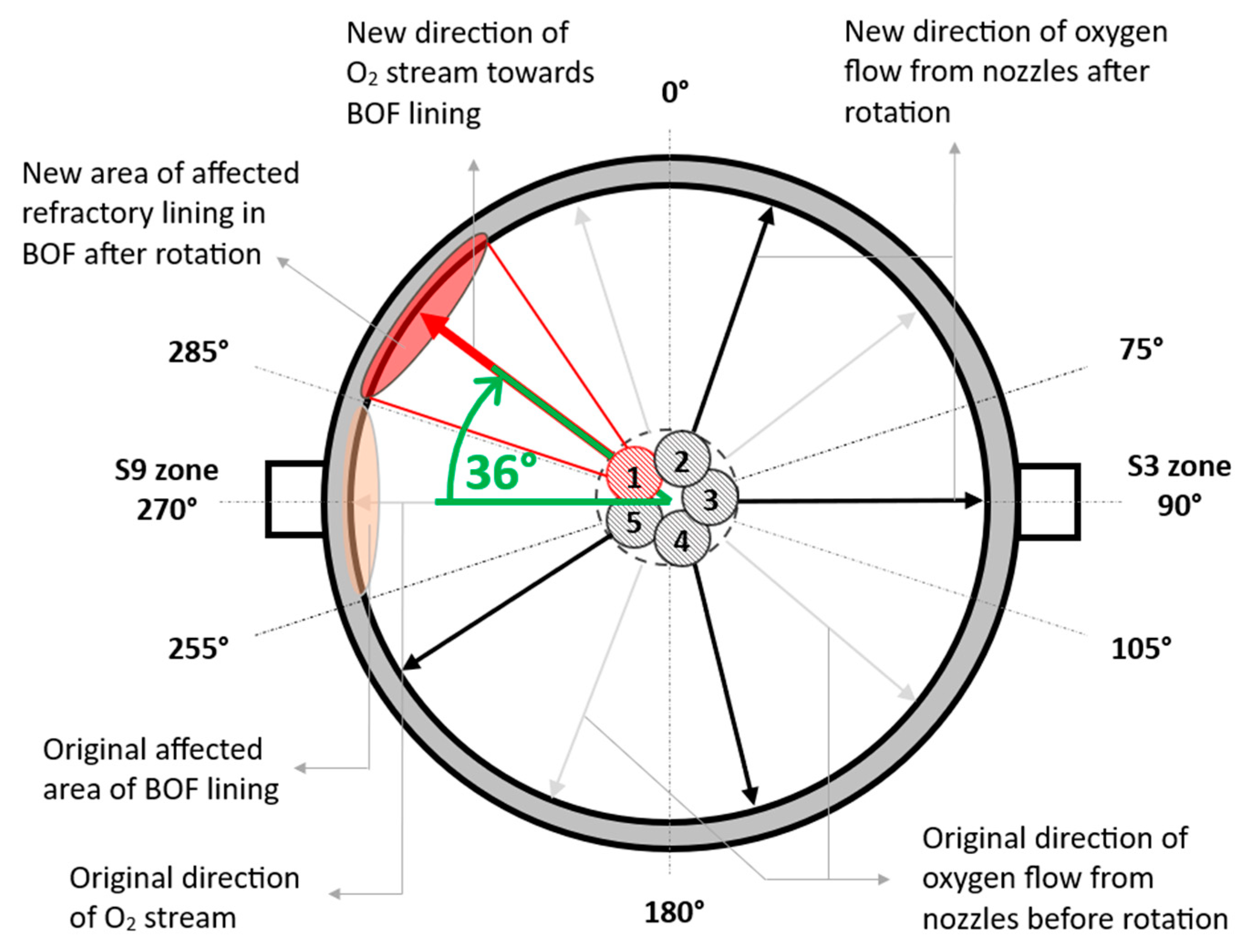
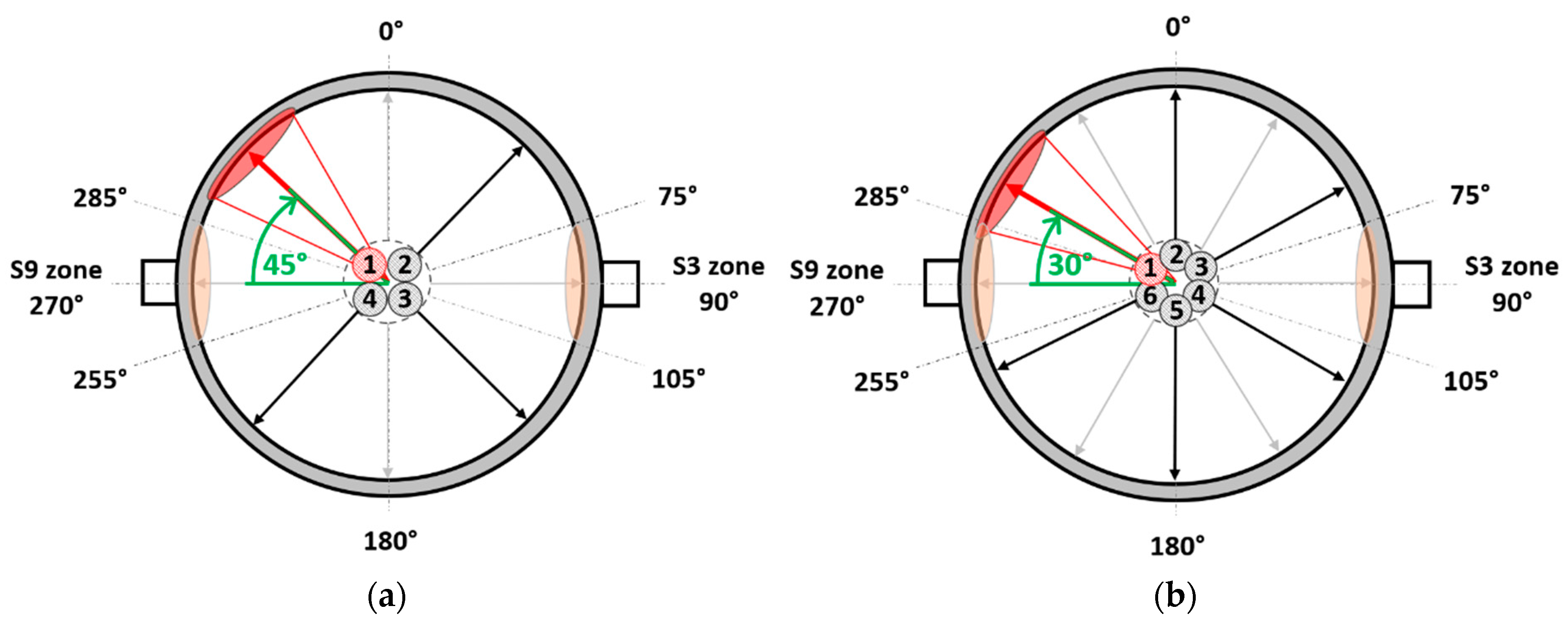
  • Turn and weld the new 5-hole copper tip of the oxygen lance by 36° from its original position when replacing a worn tip (Figure 9). When replacing a 4-hole copper tip, rotate and weld the new tip 45° from its original position (Figure 10a). When replacing a 6-hole copper tip, turn and weld the new one by 30° from its initial position (Figure 10b).
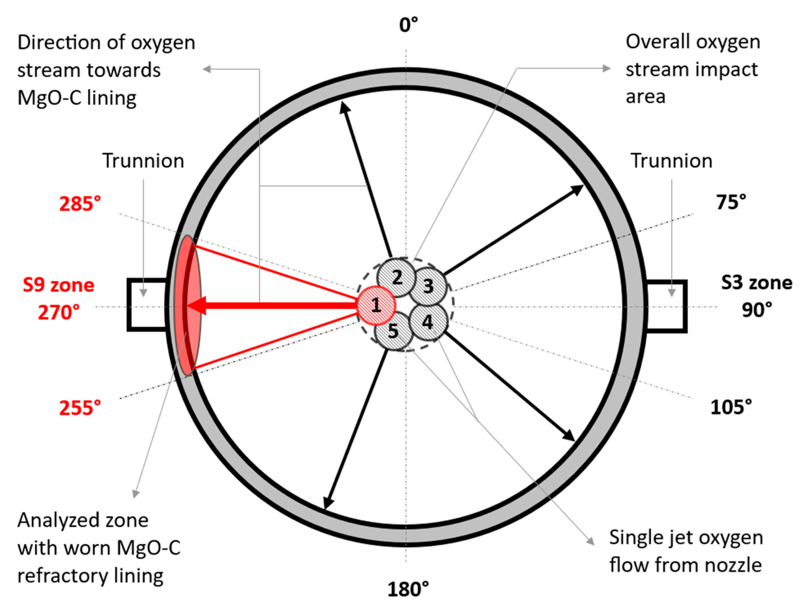
  • Using a 5-hole tip and alternating Periods 1 and 2, the copper tip rotates, exposing only one trunnion area of the MgO–C refractory lining to direct oxygen jets and molten metal and slag splashes at a time. In Period 1, the S3 zone is exposed while the opposite S9 zone is preserved. In Period 2, the roles reverse, saving the gunning mixture on the non-exposed side. Other MgO–C refractory zones in the BOF are repaired primarily through slag splashing and high-basic slag coating techniques.
  • The following position management is used when using 4-hole or 6-hole copper tip. In Period 1, nozzles expose the S3 and S9 trunnion zones to oxygen jets and molten metal and slag splashes, causing refractory wear and consuming the gunning mixture. After turning the copper tip (30° for 6-hole, 45° for 4-hole) in Period 2, no oxygen jets directly hit the trunnion areas, reducing wear and conserving the gunning mixture. Laser measurements and consumption analysis confirm no excess gunning mixture usage in non-exposed areas. Slag splashing and high-basic slag coating techniques will prioritize repairing other refractory zones.

6. Patents

As a result of the work published in this manuscript, the utility model number PUV 23-2025, entitled: A method of replacing the copper tip of the oxygen lance in the basic oxygen furnace.

Author Contributions

Conceptualization, J.D.; methodology, J.D.; validation, J.D., B.B., P.D., and D.C.; formal analysis, J.D.; investigation, J.D.; resources, J.D. and B.B.; data curation, J.D.; writing—original draft preparation, J.D.; writing—review and editing, B.B., P.D., M.H., and D.C.; visualization, J.D.; supervision, B.B. and M.H.; project administration, J.D. and B.B.; funding acquisition, B.B. All authors have read and agreed to the published version of the manuscript.

Funding

This research was funded by the Ministry of Education, Research, Development and Youth of the Slovak Republic: VEGA 1/0199/24.

Institutional Review Board Statement

Not applicable.

Informed Consent Statement

Not applicable.

Data Availability Statement

Restrictions apply to the availability of these data. The data were obtained from U.S. Steel Košice, Slovakia based on contract of cooperation No. ZOS-5/2019-FMMR and are available from the authors with the permission of U.S. Steel Košice, Slovakia.

Acknowledgments

The authors sincerely acknowledge the anonymous reviewers for their insights and comments, which further improved the quality of the manuscript.

Conflicts of Interest

Author Dáša Chudíková was employed by the company RMS Košice s.r.o. The remaining authors declare that the research was conducted in the absence of any commercial or financial relationships that could be construed as a potential conflict of interest.

References

  1. Higuchi, Y.; Tago, Y. Effect of Lance Design on Jet Behavior and Spitting Rate in Top Blown Process. ISIJ Int. 2001, 41, 1454–1459. [Google Scholar] [CrossRef]
  2. Fabritius, T.M.J.; Luomala, M.J.; Virtanen, E.O.; Tenkku, H.; Fabritius, T.L.J.; Siivola, T.P.; Härkki, J.J. Effect of Bottom Nozzle Arrangement on Splashing and Spitting in Combined Blowing Converter. ISIJ Int. 2002, 42, 861–867. [Google Scholar] [CrossRef]
  3. Sabah, S.; Brooks, G. Splash Distribution in Oxygen Steelmaking. Metall. Mater. Trans. B 2015, 46, 863–872. [Google Scholar] [CrossRef]
  4. Schacht, C. Refractories Handbook, 1st ed.; CRC Press: Boca Raton, FL, USA, 2004. [Google Scholar] [CrossRef]
  5. Li, M.; Li, Q.; Zou, Z.; An, X. Computational Investigation of Swirling Supersonic Jets Generated Through a Nozzle-Twisted Lance. Metall. Mater. Trans. B 2017, 48, 713–725. [Google Scholar] [CrossRef]
  6. Lv, M.; Chen, S.; Yang, L.; Wei, G. Research Progress on Injection Technology in Converter Steelmaking Process. Metals 2022, 12, 1918. [Google Scholar] [CrossRef]
  7. Luomala, M.J.; Fabritius, T.M.J.; Virtanen, E.O.; Siivola, T.P.; Härkki, J.J. Splashing and Spitting Behaviour in the Combined Blown Steelmaking Converter. ISIJ Int. 2002, 42, 944–949. [Google Scholar] [CrossRef]
  8. Fruehan, R.J. The Making, Shaping, and Treating of Steel: Steelmaking and Refining Volume, 11th ed.; The AISE Steel Foundation: Pittsburgh, PA, USA, 1998; ISBN 978-0-930767-03-7. [Google Scholar]
  9. Lv, M.; Zhu, R. Research on Coherent Jet Oxygen Lance in BOF Steelmaking Process. Metall. Res. Technol. 2019, 116, 502. [Google Scholar] [CrossRef]
  10. Li, M.; Li, Q.; Kuang, S.B.; Zou, Z. Coalescence Characteristics of Supersonic Jets From Multi-Nozzle Oxygen Lance in Steelmaking BOF. Steel Res. Int. 2015, 86, 1517–1529. [Google Scholar] [CrossRef]
  11. Bhattacharya, T.; Zhan, L.; Chukwulebe, B. Design Considerations of Supersonic Oxygen Lances for a Basic Oxygen Furnace (BOF). ResearchGate 2016. Available online: https://www.researchgate.net/publication/305612005 (accessed on 13 March 2025).
  12. Kärnä, A.; Järvinen, M.P.; Fabritius, T. CFD Modeling of a Supersonic Top Blown Lance in a CAS-OB Process: Development of Gas Heat and Mass Transfer Correlation. Steel Res. Int. 2015, 86, 1370–1378. [Google Scholar] [CrossRef]
  13. Alam, M.; Naser, J.; Brooks, G. Computational Fluid Dynamics Simulation of Supersonic Oxygen Jet Behavior at Steelmaking Temperature. Metall. Mater. Trans. B 2010, 41, 636–645. [Google Scholar] [CrossRef]
  14. Sumi, I.; Kishimoto, Y.; Kikuchi, Y.; Igarashi, H. Effect of High-Temperature Field on Supersonic Oxygen Jet Behavior. ISIJ Int. 2006, 46, 1312–1317. [Google Scholar] [CrossRef]
  15. Li, M.; Li, Q.; Li, L.; He, Y.; Zou, Z. Effect of Operation Parameters on Supersonic Jet Behaviour of BOF Six-Nozzle Oxygen Lance. Ironmak. Steelmak. 2014, 41, 699–709. [Google Scholar] [CrossRef]
  16. Tago, Y.; Higuchi, Y. Fluid Flow Analysis of Jets from Nozzles in Top Blown Process. ISIJ Int. 2003, 43, 209–215. [Google Scholar] [CrossRef]
  17. Naito, K.; Ogawa, Y.; Inomoto, T.; Kitamura, S.; Yano, M. Characteristics of Jets from Top-Blown Lance in Converter. ISIJ Int. 2000, 40, 23–30. [Google Scholar] [CrossRef]
  18. Sambasivam, R.; Durst, F. Characteristics of Supersonic Jets in LD Steelmaking. Ironmak. Steelmak. 2010, 37, 195–203. [Google Scholar] [CrossRef]
  19. Wang, W.; Yuan, Z.; Matsuura, H.; Zhao, H.; Dai, C.; Tsukihashi, F. Three-Dimensional Compressible Flow Simulation of Top-Blown Multiple Jets in Converter. ISIJ Int. 2010, 50, 491–500. [Google Scholar] [CrossRef]
  20. Li, M.; Li, Q.; Kuang, S.; Zou, Z. Transferring Characteristics of Momentum/Energy during Oxygen Jetting into the Molten Bath in BOFs: A Computational Exploration. Steel Res. Int. 2016, 87, 288–300. [Google Scholar] [CrossRef]
  21. Liu, F.; Zhu, R.; Dong, K.; Hu, S. Flow Field Characteristics of Coherent Jet with Preheating Oxygen under Various Ambient Temperatures. ISIJ Int. 2016, 56, 1519–1528. [Google Scholar] [CrossRef]
  22. Yin, Z.; Lu, J.; Li, L.; Wang, T.; Wang, R.; Fan, X.; Lin, H.; Huang, Y.; Tan, D. Optimized Scheme for Accelerating the Slagging Reaction and Slag–Metal–Gas Emulsification in a Basic Oxygen Furnace. Appl. Sci. 2020, 10, 5101. [Google Scholar] [CrossRef]
  23. Odenthal, H.-J.; Falkenreck, U.; Schlüter, J. CFD Simulation of Multiphase Melt Flows in Steelmaking Converters. In Proceedings of the European Conference on Computational Fluid Dynamics ECCOMAS CFD, Egmond aan Zee, The Netherlands, 5–8 September 2006. [Google Scholar]
  24. Kadrolkar, A.; Dogan, N. Model Development for Refining Rates in Oxygen Steelmaking: Impact and Slag-Metal Bulk Zones. Metals 2019, 9, 309. [Google Scholar] [CrossRef]
  25. Li, Q.; Li, M.; Kuang, S.; Zou, Z. Numerical Simulation of the Interaction Between Supersonic Oxygen Jets and Molten Slag–Metal Bath in Steelmaking BOF Process. Metall. Mater. Trans. B 2015, 46, 1494–1509. [Google Scholar] [CrossRef]
  26. Cao, L.; Wang, Y.; Liu, Q.; Feng, X. Physical and Mathematical Modeling of Multiphase Flows in a Converter. ISIJ Int. 2018, 58, 573–584. [Google Scholar] [CrossRef]
  27. Sun, J.; Zhang, J.; Lin, W.; Cao, L.; Feng, X.; Liu, Q. Effect of Impact Cavity Shape Induced by Supersonic Oxygen Jet on the Dynamic Characteristics of Molten Bath in Converter. Steel Res. Int. 2021, 92, 2100179. [Google Scholar] [CrossRef]
  28. Lv, M.; Zhu, R.; Guo, Y.-G.; Wang, Y.-W. Simulation of Flow Fluid in the BOF Steelmaking Process. Metall. Mater. Trans. B 2013, 44, 1560–1571. [Google Scholar] [CrossRef]
  29. Liu, G.; Liu, K.; Han, P. Metallurgical Performance of Innovative Double-Parameter Oxygen Lance in BOF Steelmaking. Ironmak. Steelmak. 2020, 48, 437–446. [Google Scholar] [CrossRef]
  30. Yuan, Z.; Yang, X.; Lu, Z.; Huang, J.; Pan, Y.; Ma, E. Jet Behavior and Metallurgical Performance of Innovated Double-Parameter Oxygen Lance in BOF. J. Iron Steel Res. Int. 2007, 14, 1–5. [Google Scholar] [CrossRef]
  31. Li, J.; Zeng, Y.; Wang, J.; Han, Z. Simulation of Flow Field of Oxygen Lance Gas Jet Utilized for 50 t Converter. J. Iron Steel Res. Int. 2011, 18, 11–18. [Google Scholar] [CrossRef]
  32. Zhong, L.; Zhu, Y.; Jiang, M.; Qu, Z.; Za, Y.; Bao, X. Cold Modelling of Slag Splashing in LD Furnace by Oxygen Lance with Twisted Nozzle Tip. Steel Res. Int. 2005, 76, 611–615. [Google Scholar] [CrossRef]
  33. Higuchi, Y.; Tago, Y. Effect of Nozzle Twisted Lance on Jet Behavior and Spitting Rate in Top Blown Process. ISIJ Int. 2003, 43, 1410–1414. [Google Scholar] [CrossRef]
  34. Liu, F.; Sun, D.; Zhu, R.; Zhao, F.; Ke, J. Effect of Nozzle Twisted Oxygen Lance on Flow Field and Dephosphorisation Rate in Converter Steelmaking Process. Ironmak. Steelmak. 2017, 44, 640–648. [Google Scholar] [CrossRef]
  35. Li, L.; Li, M.; Shao, L.; Li, Q.; Zou, Z. Physical and Mathematical Modeling of Swirling Gas Jets Impinging onto a Liquid Bath Using a Novel Nozzles-Twisted Lance. Steel Res. Int. 2020, 91, 1900684. [Google Scholar] [CrossRef]
  36. Li, J.; Ma, Z.; Chen, C.; Zhang, J.; Wang, B. Behavior of Top-Blown Jet under a New Cyclone Oxygen Lance during BOF Steelmaking Process. Processes 2022, 10, 507. [Google Scholar] [CrossRef]
  37. Bahtli, T.; Hopa, D.Y.; Bostanci, V.M.; Ulvan, N.S.; Yasti, S.Y. Corrosion Behaviours of MgO–C Refractories: Incorporation of Graphite or Pyrolytic Carbon Black as a Carbon Source. Ceram. Int. 2018, 44, 6780–6785. [Google Scholar] [CrossRef]
  38. Anan, K. Wear of Refractories in Basic Oxygen Furnaces (BOF). J. Tech. Assoc. Refract. Jpn. 2001, 21, 241–246. [Google Scholar]
  39. Xiao, J.; Chen, J.; Wei, Y.; Zhang, Y.; Zhang, S.; Li, N. Oxidation Behaviors of MgO–C Refractories with Different Si/SiC Ratio in the 1100–1500 °C Range. Ceram. Int. 2019, 45, 21099–21107. [Google Scholar] [CrossRef]
  40. Zanotelli, V.H.; Ribas, L.L.; Bragança, S.R. Evaluation of Oxidation Resistance of MgO–C Bricks in Oxy-Combustion and Air-Combustion. Int. J. Appl. Ceram. Technol. 2021, 18, 1392–1403. [Google Scholar] [CrossRef]
  41. Ghosh, N.K.; Ghosh, D.N.; Jagannathan, K.P. Oxidation Mechanism of MgO–C in Air at Various Temperatures. Br. Ceram. Trans. 2000, 99, 124–128. [Google Scholar] [CrossRef]
  42. Faghihi-Sani, M.-A.; Yamaguchi, A. Oxidation Kinetics of MgO–C Refractory Bricks. Ceram. Int. 2002, 28, 835–839. [Google Scholar] [CrossRef]
  43. Liu, Z.; Yu, J.; Yang, X.; Jin, E.; Yuan, L. Oxidation Resistance and Wetting Behavior of MgO–C Refractories: Effect of Carbon Content. Materials 2018, 11, 883. [Google Scholar] [CrossRef]
  44. Hashemi, B.; Nemati, Z.A.; Sadrnezhaad, S.K.; Moghimi, Z.A. Kinetic Parameters Estimation of MgO–C Refractory by Shrinking Core Model. J. Mater. Sci. Technol. 2006, 22, 826–832. [Google Scholar]
  45. Mahato, S.; Behera, S.K. Oxidation Resistance and Microstructural Evolution in MgO–C Refractories with Expanded Graphite. Ceram. Int. 2016, 42, 7611–7619. [Google Scholar] [CrossRef]
  46. Bavand-Vandchali, M.; Golestani-Fard, F.; Sarpoolaky, H.; Rezaie, H.R.; Aneziris, C.G. The Influence of in Situ Spinel Formation on Microstructure and Phase Evolution of MgO–C Refractories. J. Eur. Ceram. Soc. 2008, 28, 563–569. [Google Scholar] [CrossRef]
  47. Luz, A.P.; Souza, T.M.; Pagliosa, C.; Brito, M.A.M.; Pandolfelli, V.C. In Situ Hot Elastic Modulus Evolution of MgO–C Refractories Containing Al, Si or Al–Mg Antioxidants. Ceram. Int. 2016, 42, 9813–9836. [Google Scholar] [CrossRef]
  48. Hu, S.; Zhu, R.; Liu, R.; Dong, K. Decarburisation Behaviour of High-Carbon MgO–C Refractories in O2-CO2 Oxidising Atmospheres. Ceram. Int. 2018, 44, 20641–20647. [Google Scholar] [CrossRef]
  49. Moliné, M.N.; Galliano, P.G.; Tomba Martinez, A.G. Chemical Degradation of Magnesia–Carbon Refractories by Different Gaseous Atmospheres. Carbon Trends 2024, 14, 100320. [Google Scholar] [CrossRef]
  50. Li, Z.; Mukai, K.; Tao, Z. Reactions Between MgO–C Refractory, Molten Slag and Metal. ISIJ Int. 2000, 40, 101–105. [Google Scholar] [CrossRef]
  51. Mukai, K.; Li, Z.; Tao, Z. Bubble Generation in MgO–C Crucible Charged with Slag and Metal in Relation to Local Corrosion. High Temp. Mater. Process. 2001, 20, 255–262. [Google Scholar] [CrossRef]
  52. Asahara, N.; Naito, K.; Kitagawa, I.; Matsuo, M.; Kumakura, M.; Iwasaki, M. Fundamental Study on Interaction between Top Blown Jet and Liquid Bath. Steel Res. Int. 2011, 82, 587–594. [Google Scholar] [CrossRef]
  53. Sambasivam, R.; Lenka, S.; Durst, F.; BOCK, M.; Chandra, S.; Ajmani, S. A New Lance Design for BOF Steelmaking. Metall. Mater. Trans. B 2007, 38, 45–53. [Google Scholar] [CrossRef]
  54. Treatise on Process Metallurgy, Volume 3: Industrial Processes. In Treatise on Process Metallurgy; Seetharaman, S., Ed.; Elsevier: Boston, MA, USA, 2014; Volume 3: Industrial Processes; pp. 231–250. ISBN 978-0-08-096988-6. [Google Scholar]
  55. Lee, W.E.; Zhang, S. Melt Corrosion of Oxide and Oxide–Carbon Refractories. Int. Mater. Rev. 1999, 44, 77–104. [Google Scholar] [CrossRef]
  56. Surendranathan, A.O. An Introduction to Ceramics and Refractories; CRC Press: Boca Raton, FL, USA, 2015; ISBN 978-0-429-06832-4. [Google Scholar]
  57. Jansson, S.; Brabie, V.; Jönsson, P. Corrosion Mechanism and Kinetic Behaviour of MgO–C Refractory Material in Contact with CaO–Al2O3–SiO2–MgO Slag. Scand. J. Metall. 2005, 34, 283–292. [Google Scholar] [CrossRef]
  58. Banerjee, S. Monolithic Refractories: A Comprehensive Handbook; American Ceramic Society: Westerville, OH, USA; World Scientific: River Edge, NJ, USA, 1998; ISBN 978-981-02-3120-0. [Google Scholar]
  59. Bruckhaus, R.; Fiedler, V.; Lachmund, V. Improvement of the BOF Process by Use of a Radar Measurement at the Dillinger Hütte. Rev. Met. Paris 2001, 98, 553–559. [Google Scholar] [CrossRef]
  60. Manchisi, J.; Matinde, E.; Rowson, N.A.; Simmons, M.J.H.; Simate, G.S.; Ndlovu, S.; Mwewa, B. Ironmaking and Steelmaking Slags as Sustainable Adsorbents for Industrial Effluents and Wastewater Treatment: A Critical Review of Properties, Performance, Challenges and Opportunities. Sustainability 2020, 12, 2118. [Google Scholar] [CrossRef]
  61. Kemminger, A.; Krause, F.; Odenthal, H.-J. CFD Simulation of Top-Blown Converters. In Proceedings of the 9th EOSC European Oxygen Steelmaking Conference, Aachen, Germany, 17–21 October 2022. [Google Scholar]
  62. Li, M.; Li, Q.; Kuang, S.; Zou, Z. Determination of Cavity Dimensions Induced by Impingement of Gas Jets onto a Liquid Bath. Metall. Mater. Trans. B 2016, 47, 116–126. [Google Scholar] [CrossRef]
  63. Ersson, M.; Tilliander, A. Review on CFD Simulation and Modeling of Decarburization Processes. Steel Res. Int. 2018, 89, 1700108. [Google Scholar] [CrossRef]
  64. Luomala, M.J.; Fabritius, T.M.J.; Härkki, J.J. The Effect of Bottom Nozzle Configuration on the Bath Behaviour in the BOF. ISIJ Int. 2004, 44, 809–816. [Google Scholar] [CrossRef]
  65. Jia, H.; Li, Y.; Han, P.; Liu, K.; Han, H.; Feng, L. Turbulence Calculations of a Dual-Structure Oxygen Lance for Converter Based on Hydrodynamics. Math. Probl. Eng. 2021, 2021, e5785889. [Google Scholar] [CrossRef]
  66. Hu, J.; Yang, Q.; Yang, S.; Yu, H.; Wang, H. Enhanced Impingement Characteristics of Supersonic Oxygen Jets on Molten Bath Using a Multi-Nozzle Oxygen Lance in a Converter. ISIJ Int. 2024, 64, 773–784. [Google Scholar] [CrossRef]
  67. Bhattacharya, T.; Zhan, L.; Chukwulebe, B. A Numerical Test Bench for Supersonic Oxygen Nozzles and Its Application to the BOF Process. AISTech Iron Steel Technol. Conf. Proc. 2014, 1, 1149–1158. [Google Scholar]
  68. Park, J.M.; Ha, C.S. Recent Improvement of BOF Refining at Kwangyang Works. Rev. Met. Paris 2000, 97, 729–735. [Google Scholar] [CrossRef]
  69. Lee, M.S.; O’Rourke, S.L.; Molloy, N.A. Oscillatory Flow in the Steelmaking Vessel. Scand. J. Metall. 2003, 32, 281–288. [Google Scholar] [CrossRef]
  70. Sabah, S.; Brooks, G. Splashing in Oxygen Steelmaking. ISIJ Int. 2014, 54, 836–844. [Google Scholar] [CrossRef]
  71. Kalifa, R.B.; Hamza, S.B.; Saïd, N.M.; Bournot, H. Fluid Flow Phenomena in Metals Processing Operations: Numerical Description of the Fluid Flow Field by an Impinging Gas Jet on a Liquid Surface. Int. J. Mech. Sci. 2020, 165, 105220. [Google Scholar] [CrossRef]
  72. Altohami, A.M.; Omer, A.A. Fluid Flow, Heat Transfer, Mixing Time and Inclusion Motion in Molten Steel Continuous Casting Tundish. Int. J. Eng. Trends Technol. IJETT. 2017, 49, 231–243. [Google Scholar]
  73. Iguchi, M.; Ilegbusi, O.J. Basic Transport Phenomena in Materials Engineering; Springer Japan: Tokyo, Japan, 2014; ISBN 978-4-431-54019-9. [Google Scholar]
  74. Amano, S.; Sato, S.; Takahashi, Y.; Kikuchi, N. Effect of Top and Bottom Blowing Conditions on Spitting in Converter. Eng. Rep. 2021, 3, e12406. [Google Scholar] [CrossRef]
  75. Li, Q.; Li, M.; Kuang, S.B.; Zou, Z. Understanding Characteristic of Abrasion of Refractory Lining Caused by Bath Oscillation in BOF Steelmaking. JOM 2016, 68, 3126–3133. [Google Scholar] [CrossRef]
  76. He, Q.L.; Standish, N. A Model Study of Residence Time of Metal Droplets in the Slag in BOF Steelmaking. ISIJ Int. 1990, 30, 356–361. [Google Scholar] [CrossRef]
  77. Deo, B.; Overbosch, A.; Snoeijer, B.; Das, D.; Srinivas, K. Control of Slag Formation, Foaming, Slopping, and Chaos in BOF. Trans. Indian Inst. Met. 2013, 66, 543–554. [Google Scholar] [CrossRef]
  78. Wang, R.; Zhang, B.; Liu, C.; Jiang, M. A Novel Modeling Method of Slag Foaming in BOF. Metall. Mater. Trans. B 2020, 51, 1941–1946. [Google Scholar] [CrossRef]
  79. Wang, R.; Zhang, B.; Hu, C.; Liu, C.; Jiang, M. Study on Splashing Mechanism in Basic Oxygen Furnace Based on Slag Foaming Modeling. Steel Res. Int. 2022, 93, 2100318. [Google Scholar] [CrossRef]
  80. Liu, Z.; Yuan, L.; Jin, E.; Yang, X.; Yu, J. Wetting, Spreading and Corrosion Behavior of Molten Slag on Dense MgO and MgO–C Refractory. Ceram. Int. 2019, 45, 718–724. [Google Scholar] [CrossRef]
  81. Martinsson, J.; Glaser, B.; Sichen, D. The Structure of Foaming BOF-Converter Slag. Ironmak. Steelmak. 2019, 46, 777–781. [Google Scholar] [CrossRef]
  82. Martinsson, J.; Glaser, B.; Sichen, D. Lime Dissolution in Foaming BOF Slag. Metall. Mater. Trans. B 2018, 49, 3164–3170. [Google Scholar] [CrossRef]
  83. Jiang, R.; Fruehan, R.J. Slag Foaming in Bath Smelting. Metall. Trans. B 1991, 22, 481–489. [Google Scholar] [CrossRef]
  84. Ito, K.; Fruehan, R.J. Slag Foaming in Smelting Reduction Processes. Steel Res. 1989, 60, 151–156. [Google Scholar] [CrossRef]
  85. Yao, L.; Zhu, R.; Tang, Y.; Wei, G.; Dong, K. Effect of Furnace Gas Composition on Characteristics of Supersonic Oxygen Jets in the Converter Steelmaking Process. Materials 2020, 13, 3353. [Google Scholar] [CrossRef]
  86. Li, M.; Li, Q.; Li, L.; Feng, M.; Zhang, Z.; Zou, Z. Numerical Study on Behavior of Top-Blown Supersonic Jets and Their Interaction with Bath in BOF Steelmaking Convertor. In Proceedings of the 8th Pacific Rim International Congress on Advanced Materials and Processing, Waikoloa, HI, USA, 4–9 August 2013; Marquis, F., Ed.; Springer International Publishing: Cham, Switzerland, 2016; pp. 3033–3040. [Google Scholar]
  87. Cao, L.L.; Liu, Q.; Wang, Z.; Li, N. Interaction Behaviour between Top Blown Jet and Molten Steel during BOF Steelmaking Process. Ironmak. Steelmak. 2016, 45, 239–248. [Google Scholar] [CrossRef]
Figure 1. Diagram of a general 5-hole BOF copper tip [8]: (a) vertical view; (b) lateral cross-section view.
Applsci 15 05109 g001
Figure 2. Schematic drawing of analyzed areas of MgO–C refractory lining in BOF.
Applsci 15 05109 g002
Figure 3. A schematic diagram of the recirculation flow of the CO-CO2-O2 gaseous mixture during the BOF steelmaking process.
Applsci 15 05109 g003
Figure 4. The evolution of the gunning mixture (GM) consumption per heat in the most exposed areas of the MgO–C refractory lining throughout the campaign.
Applsci 15 05109 g004
Figure 5. Thickness change of the refractory lining in BOF in S3 and S9 zones over whole campaign: (a) trunnion area; (b) slag line area.
Applsci 15 05109 g005
Figure 6. Changes in the thickness of the BOF refractory lining at specific stages of the analyzed campaign within S3 and S9 zones. Heats: (a) 28–6055, (b) 6056–11,349, (c) 11,350–13,609, (d) 13,610–16,400, and (e) 16,401–17,669.
Applsci 15 05109 g006
Figure 7. A visual representation of the projected oxygen streams blown from a 5-hole BOF lance tip. The MgO–C refractory wear area is shown in red.
Applsci 15 05109 g007
Figure 8. A lateral cross-section view of the BOF and visualization of the refractory lining in the height 4–5.2 m: (a) a lateral cross-section view of the trunnion area that cannot be repaired by the slag coating technique; (b) a lateral cross-section view of the full range of the 360° wall ring affected by direct oxygen jet, by splashing and spitting of the melt, and by the recirculation flow of the metal–slag–gas emulsion.
Applsci 15 05109 g008
Figure 9. The diagram illustrates a proposed method for reducing the localized wear of the BOF refractory lining in the case of 5-hole tip deployment. Turning the copper tip from the initial position (Period 1) to the turned position (Period 2).
Applsci 15 05109 g009
Figure 10. The principle of rotation of the copper tip of the oxygen lance during its replacement from the initial position (Period 1) to the turned position (Period 2): (a) 4-hole tip; (b) 6-hole tip.
Applsci 15 05109 g010
Table 1. Chemical composition and physical parameters of MgO–C refractory material used in trunnion zones.
Chemical
Composition
(wt.%)
MgO in magnesiamin. 98.0
SiO2 in magnesiamax. 0.4
CaO in magnesiamin. 1.2
Fe2O3 in magnesiamax. 0.5
Magnesia content 86.5
Residual carbon content 13.5
Physical
Parameters
Volumetric mass min. 2920 kg.m−3
Cold compressive strength min. 27 MPa
Apparent porositymax. 4%
Table 2. Chemical composition and physical parameters of gunning refractory mixtures used in trunnion zones during campaign.
Chemical
Composition
(wt.%)
MgO87.8
CaO7.7
P2O52.7
SiO21.3
Al2O30.4
Fe2O30.1
Physical
Parameters
Operating temperature1750 °C
Granularity0–3 mm
Volumetric mass2200 kg·m−3
Table 3. Technical details of oxygen lance and copper tip used during BOF campaign.
Technical ParameterValue
Oxygen lance length22.795 m
Amount of oxygen blownmax. 650 m3
Pressure of blowing oxygenmax. 1.6 MPa
Purity of blown oxygenmin. 99.5%
Amount of cooling water190 m3·h−1
Temperature difference in the cooling watermax. 15 °C
Number of nozzles on the tip5-hole
Critical nozzle diameter34.9 mm
Inclination angle14°
Impact area1.67 m2
Diameter of impact1.27 m
Table 4. Total gunning mix consumption for specific areas of zonal BOF lining.
BOF Lining FieldZone
Label
Affected
Angle
Share in the Total
Consumption %
Overall Consumption %
Trunnion zoneS3(75–105°)1.3418.13
Trunnion zoneS9(225–285°)16.79
Slag line zoneS3(75–105°)44.8344.93
Slag line zoneS9(225–285°)0.10
Other zones
(charge pad, tap pad,
tap hole, cone area)
--36.9436.94
Table 5. Position management of oxygen lance copper tips depending on number of nozzles.
Number of the Nozzles
on the Copper Tip
The Value of the Rotation
During Tip Replacement
4-hole45°
5-hole36°
6-hole30°
Disclaimer/Publisher’s Note: The statements, opinions and data contained in all publications are solely those of the individual author(s) and contributor(s) and not of MDPI and/or the editor(s). MDPI and/or the editor(s) disclaim responsibility for any injury to people or property resulting from any ideas, methods, instructions or products referred to in the content.

