
Analytical Investigations of Nonlinear Stiffness Characteristics of Halbach-Cylinder Magnetic Springs for Heavy-Load Capacity


Abstract
1. Introduction
2. Force and Stiffness Characteristics of Circular Magnetic Springs
2.1. DifferentConfigurations of Circular Magnetic Springs
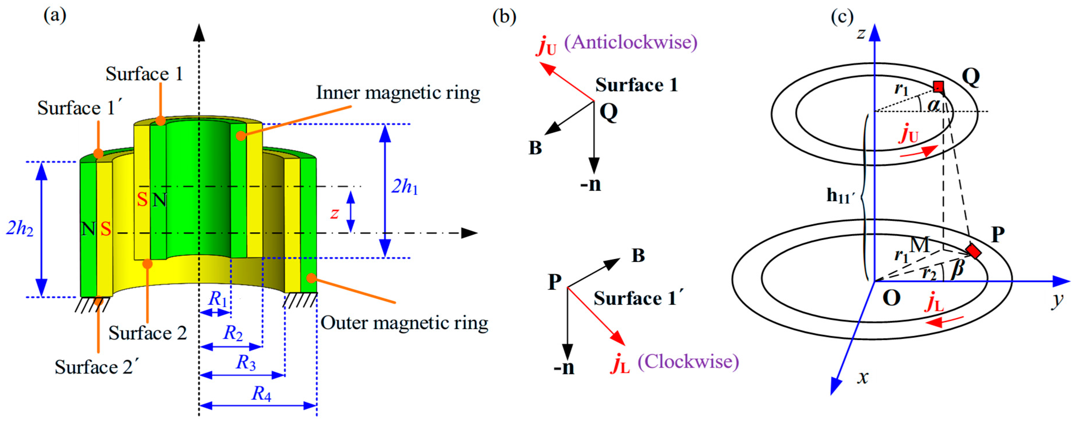
2.2. Magnetic Force and Stiffness of Each Basic CMS
2.2.1. Type I CMSs
2.2.2. Type II CMSs
2.2.3. Type III CMSs and Type IV CMSs
3. Analytical Stiffness of Halbach-Cylinder Magnetic Spring
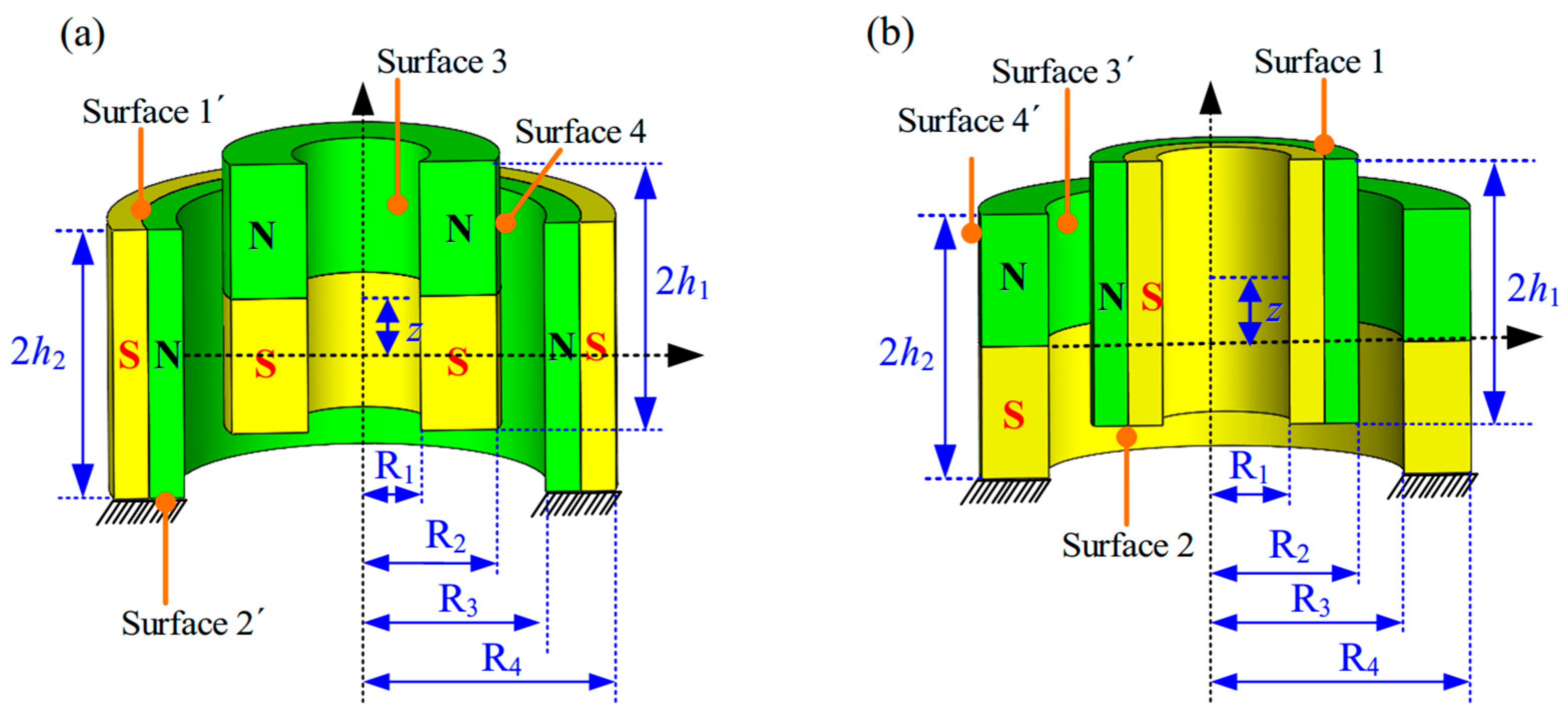
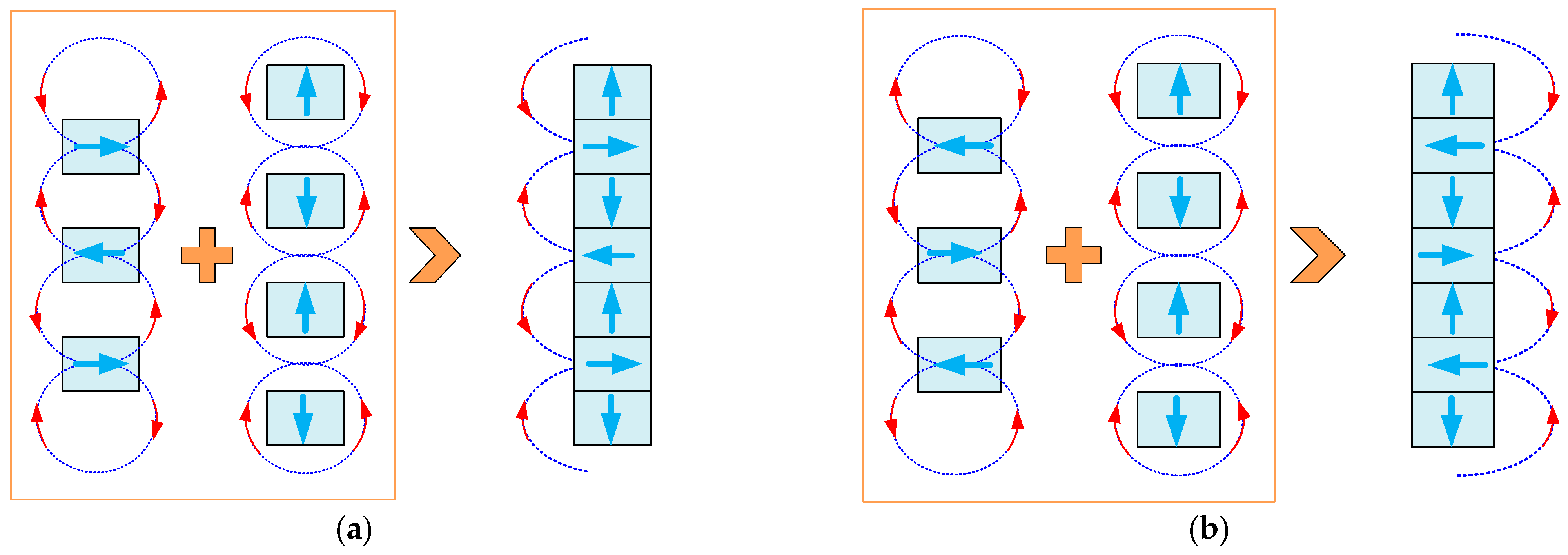
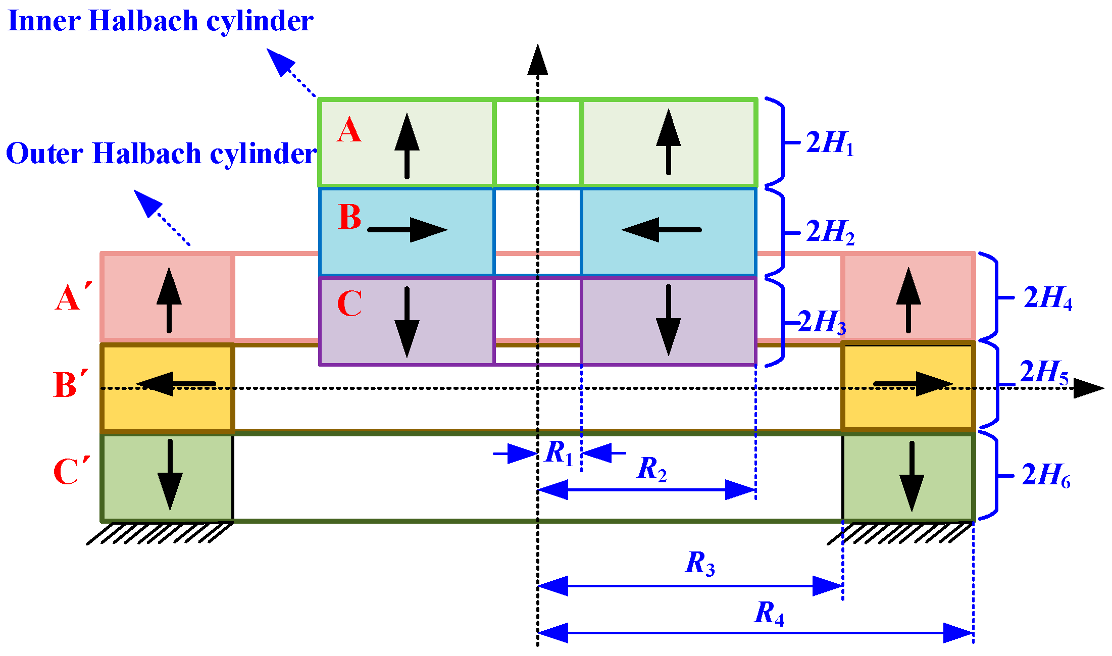
3.1. Basic Configuration of an HCMS
3.2. Stiffness Formulationof the 3-3-Type HCMS
4. Parametric Analysis of Negative Stiffness of Basic CMSs
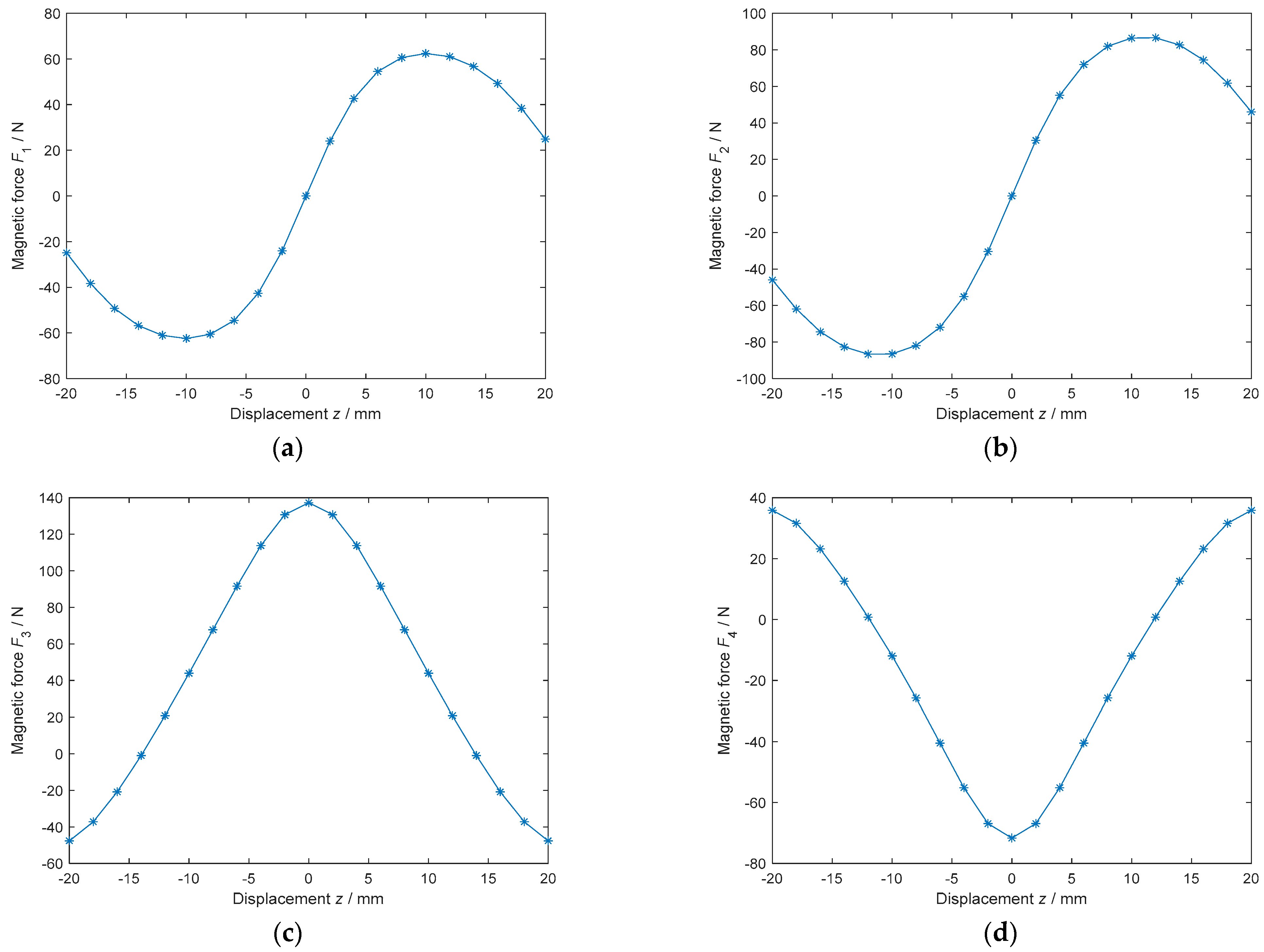
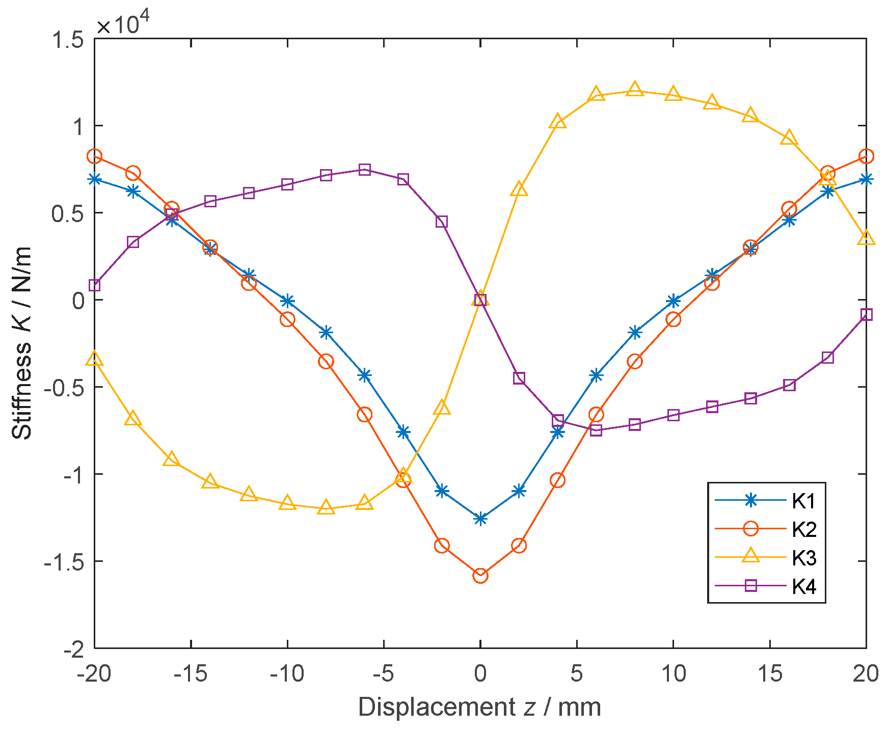
4.1. Stiffness Curves of the Four Basic CMSs
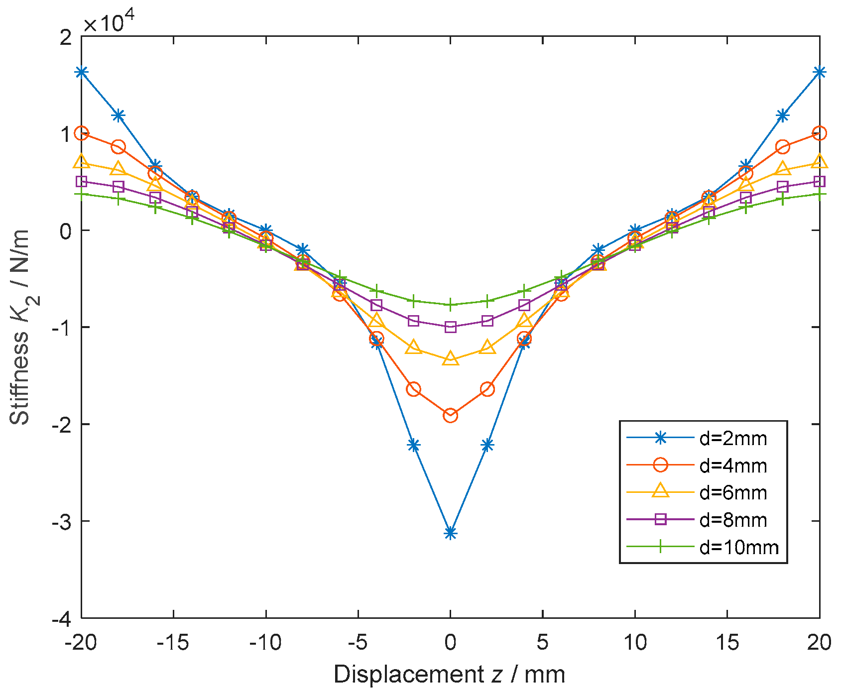
4.2. Effects of the Axial Thicknesson
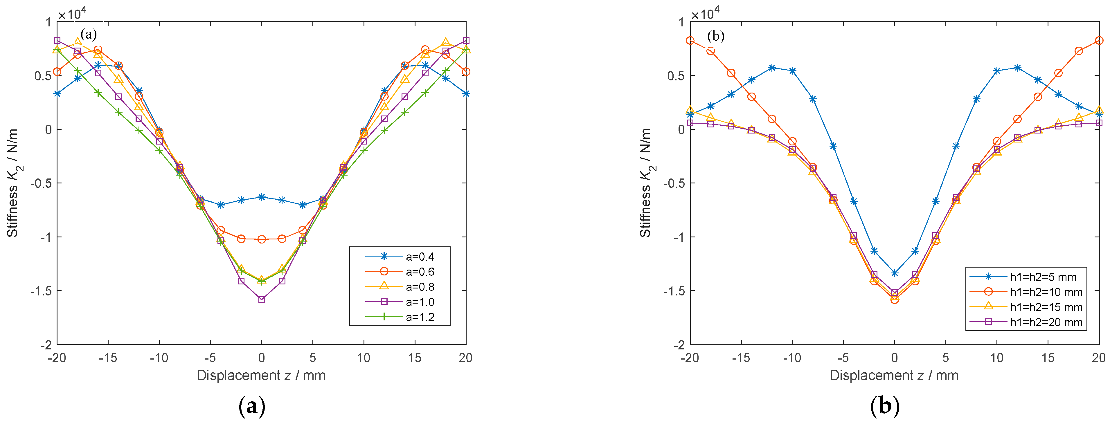
4.3. Effects of the Radial Thickness Ratio on
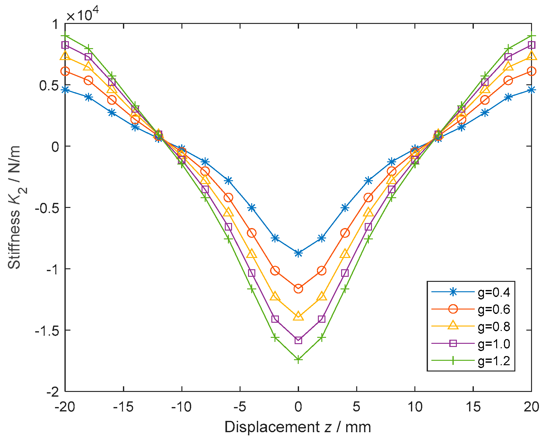
4.4. Effects of the Gap () on
5. Parametric Analysis of Negative Stiffness of the 3-3-Type HCMS
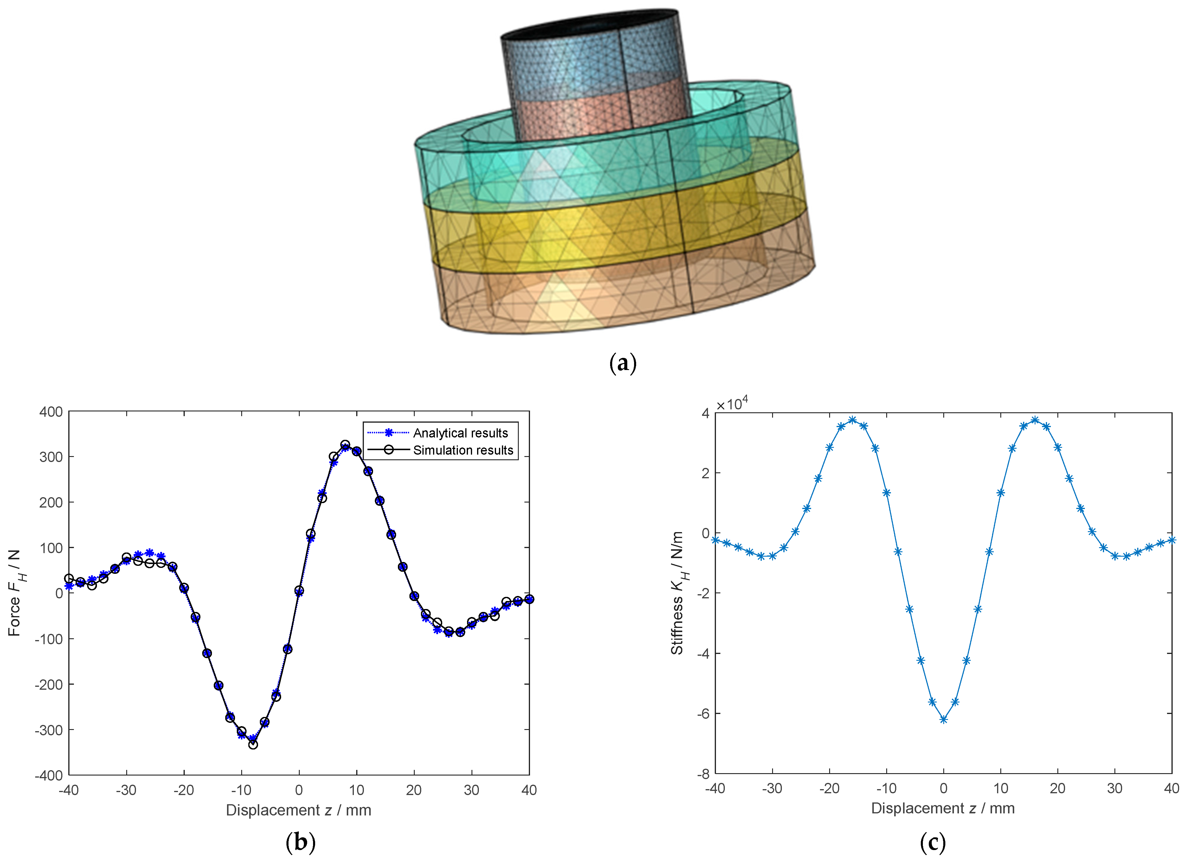
5.1. Validation of the Analytical Model by Finite Element Modeling
5.2. Comparison of the 3-3-Type HCMS with a Traditional Single-Layer CMS
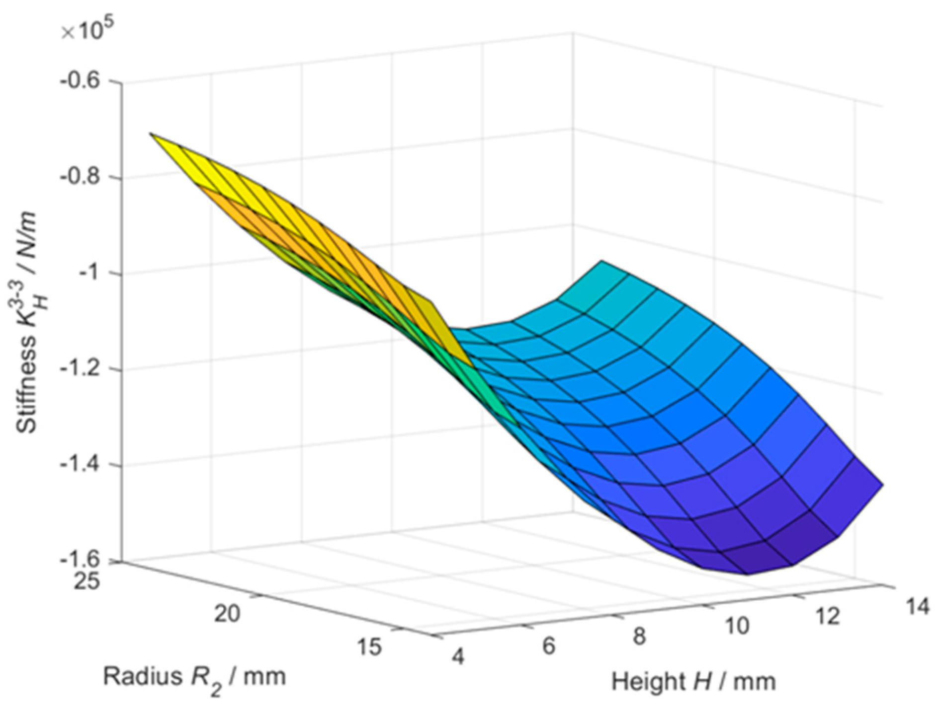
5.3. Effects of Geometric Parameters on
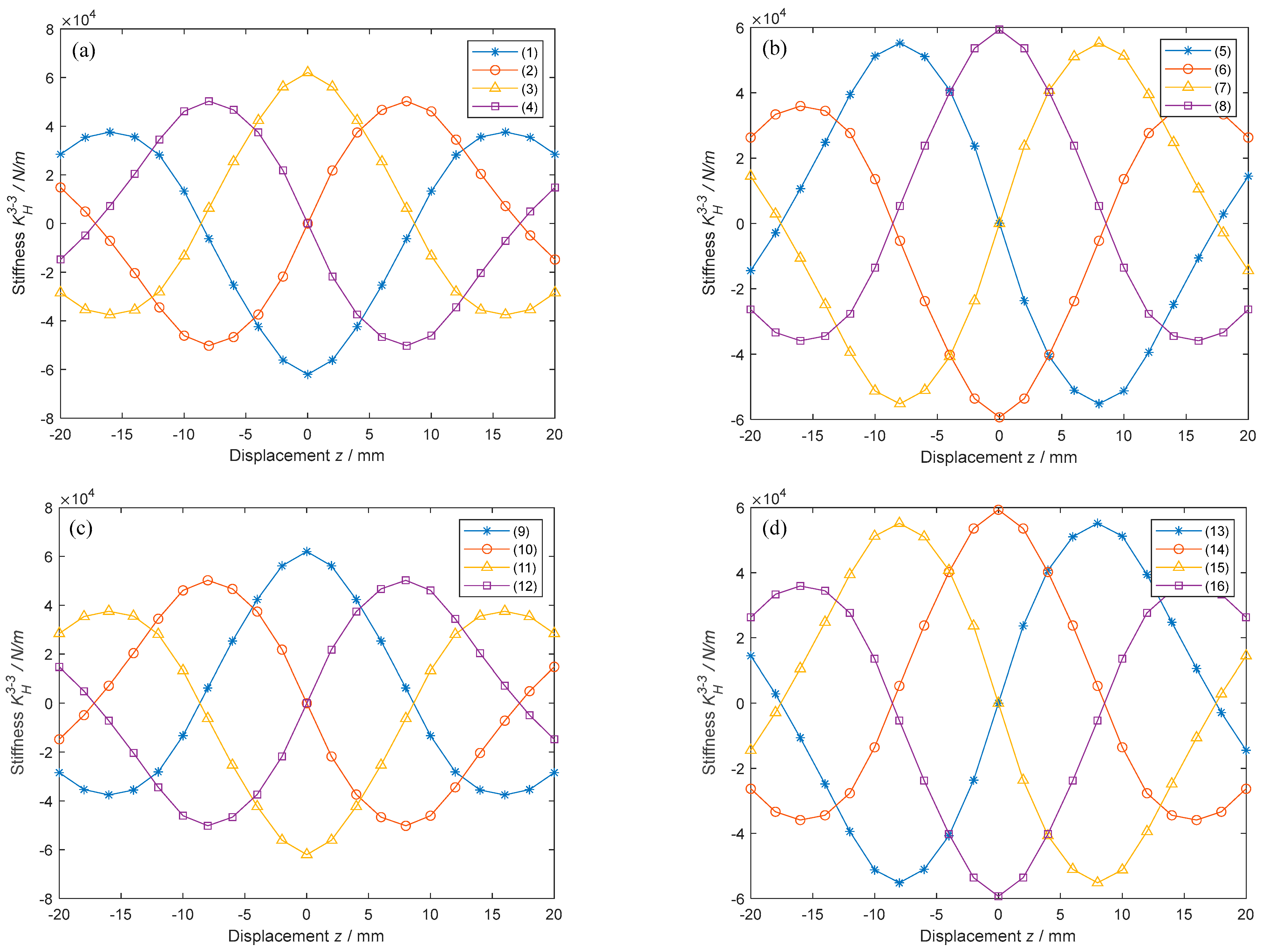
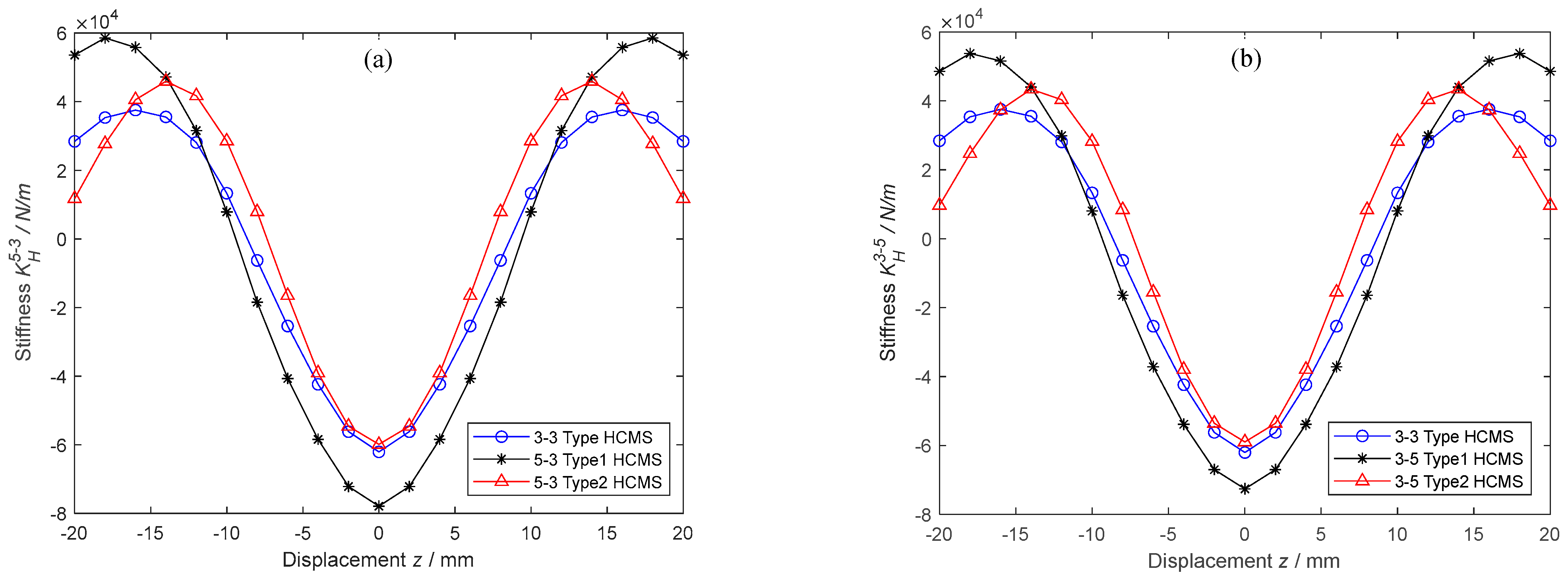
5.4. Nonlinear Stiffness Characteristics of All 3-3-Type HCMSs
5.5. A Case Study on Optimizing the Structure of the 3-3-Type HCMS
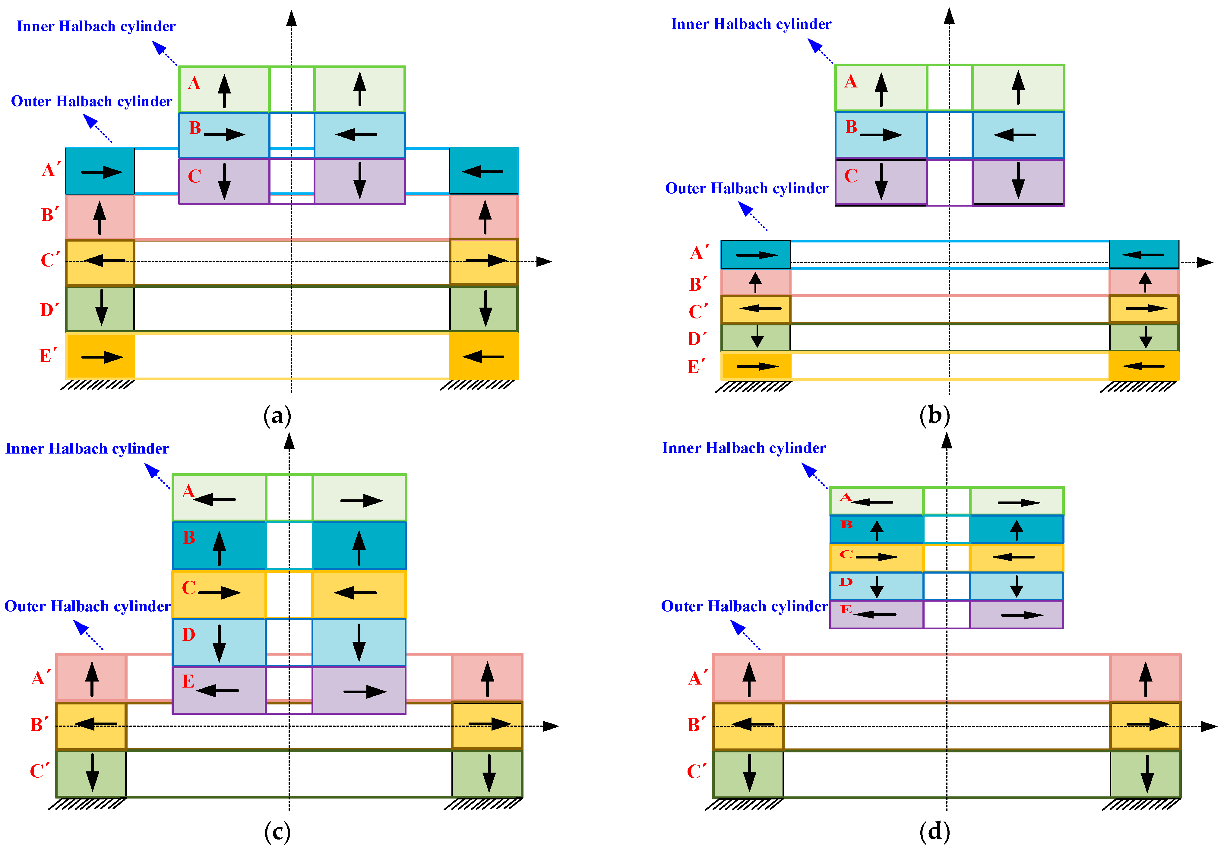
6. Potential Solution for HCMSs with Larger-Amplitude and Wider-Range Negative Stiffness
7. Conclusions
Author Contributions
Funding
Data Availability Statement
Acknowledgments
Conflicts of Interest
Abbreviations
| CMS | Circular magnetic spring |
| FEM | Finite element model |
| HCMS | Halbach-cylinder magnetic spring |
| HSLD | High static and low dynamic |
| QZS | Quasi-zero stiffness |
References
- Guruguntla, V.; Lal, M.; Ghantasala, G.S.P.; Vidyullatha, P.; Alqahtani, M.S.; Alsubaie, N.; Abbas, M.; Soufiene, B.O. Ride comfort and segmental vibration transmissibility analysis of an automobile passenger model under whole body vibration. Sci. Rep. 2023, 13, 11619. [Google Scholar] [CrossRef] [PubMed]
- Okwudire, C.E.; Lee, J.Y. Minimization of the residual vibrations of ultra-precision manufacturing machines via optimal placement of vibration isolators. Precis. Eng. 2013, 37, 425–432. [Google Scholar] [CrossRef]
- Maneerat, P.; Rungskunroch, P. Impact of earthquakes on California’s Railways: A comprehensive correlation analysis of magnitude and hypocenter depths with infrastructure accident. Transp. Res. Interdisc. 2024, 24, 101082. [Google Scholar] [CrossRef]
- Wang, Z.; Fan, K.Q.; Zhao, S.Z.; Wu, S.X.; Zhang, X.; Zhai, K.J.; Li, Z.Q.; He, H. Archery-inspired catapult mechanism with controllable energy release for efficient ultralow-frequency energy harvesting. Appl. Energy 2024, 356, 122400. [Google Scholar] [CrossRef]
- Alabuzhev, P.M. Vibration Protection and Measuring Systems with Quasi-Zero Stiffness; CRC Press: Boca Raton, FL, USA, 1989. [Google Scholar]
- Yan, G.; Zou, H.X.; Wang, S. Large stroke quasi-zero stiffness vibration isolator using three-link mechanism. J. Sound Vib. 2020, 478, 115344. [Google Scholar] [CrossRef]
- Gatti, G.; Shaw, A.D.; Gonalves, P.J.P. On the detailed design of a quasi-zero stiffness device to assist in the realisation of a translational Lanchester damper. Mech. Syst. Signal Process. 2020, 164, 108258. [Google Scholar] [CrossRef]
- Carrella, A.; Brennan, M.J.; Kovacic, I. On the force transmissibility of a vibration isolator with quasi-zero-stiffness. J. Sound Vib. 2009, 322, 707–717. [Google Scholar] [CrossRef]
- Liu, C.; Yu, K. Superharmonic resonance of the quasi-zero-stiffness vibration isolator and its effect on the isolation performance. Nonlinear Dyn. 2020, 100, 95–117. [Google Scholar] [CrossRef]
- Liu, X.; Huang, X.; Hua, H. On the characteristics of a quasi-zero stiffness isolator using Euler buckled beam as negative stiffness corrector. J. Sound Vib. 2013, 332, 3359–3376. [Google Scholar] [CrossRef]
- Li, M.; Cheng, W.; Xie, R. A quasi-zero-stiffness vibration isolator using a cam mechanism with user-defined profile. Int. J. Mech. Sci. 2021, 189, 1059. [Google Scholar] [CrossRef]
- Chen, Z.S.; Chen, Z.W.; Nie, G.F.; Li, K.Q. Analytical and experimental investigations on low-frequency simultaneous vibration isolation and energy harvesting using magnetic rings. IEEE Access 2024, 12, 32668–32678. [Google Scholar] [CrossRef]
- Zhu, Q.B.; Chai, K. Magnetic negative stiffness devices for vibration isolation systems: A state-of-the-art review from theoretical models to engineering applications. Appl. Sci. 2024, 14, 4698. [Google Scholar] [CrossRef]
- Wu, J.L.; Zeng, L.Z.; Han, B.; Zhou, Y.F.; Luo, X.; Li, X.Q.; Chen, X.D.; Jiang, W. Analysis and design of a novel arrayed magnetic spring with high negative stiffness for low-frequency vibration isolation. Int. J. Mech. Sci. 2022, 216, 106980. [Google Scholar] [CrossRef]
- Li, B.L.; Wang, W.; Li, Z.L.; Wei, R.H. Hand-held rolling magnetic-spring energy harvester: Design, analysis, and experimental verification. Energ. Convers. Manag. 2024, 301, 118022. [Google Scholar] [CrossRef]
- Akoun, G.; Yonnet, J.P. 3D Analytical calculation of the forces exerted between two cuboidal magnets. IEEE Trans. Magn. 1984, 20, 1962–1964. [Google Scholar] [CrossRef]
- Zheng, Y.S.; Zhang, X.N.; Luo, Y.J.; Yan, B.; Ma, C.C. Design and experiment of a high-static-low-dynamic stiffness isolator using a negative stiffness magnetic spring. J. Sound Vib. 2016, 360, 31–52. [Google Scholar] [CrossRef]
- Yu, N.; Fei, X.Y.; Sun, H.; Wu, Z.M.; Yan, B. Rhombus-type magnetic-levitation structure for low-frequency vibration isolation. Mech. Syst. Signal Process. 2025, 225, 112289. [Google Scholar] [CrossRef]
- Zhou, J.X.; Wang, K.; Xu, D.L.; Ouyang, H.J.; Fu, Y.M. Vibration isolation in neonatal transport by using a quasi-zero-stiffness isolator. J. Vib. Control 2018, 24, 3278–3291. [Google Scholar] [CrossRef]
- Chen, Z.W.; Chen, Z.S.; Wei, Y.X. Quasi-zero stiffness-based synchronous vibration isolation and energy harvesting: A comprehensive review. Energies 2022, 15, 7066. [Google Scholar] [CrossRef]
- Leng, D.X.; Zhu, Z.H.; Xu, K.; Li, Y.C.; Liu, G.J. Vibration control of jacket offshore platform through magnetorheological elastomer (MRE) based isolation system. Appl. Ocean Res. 2021, 114, 102779. [Google Scholar] [CrossRef]
- Halbach, K. Design of permanent multipole magnets with oriented rare earth cobalt material. Nucl. Instrum. Methods Phys. Res. 1980, 169, 1–10. [Google Scholar] [CrossRef]
- Halbach, K. Applications of permanent magnets in accelerators and electron storage rings. J. Appl. Phys. 1985, 57, 3605–3608. [Google Scholar] [CrossRef]
- Lee, M.G.; Lee, S.Q.; Gweon, D.G. Analysis of Halbach magnet array and its application to linear motor. Mechatronics 2004, 14, 115–128. [Google Scholar] [CrossRef]
- Chen, Z.S.; Chen, Z.W.; Wei, Y.X.; Xiong, Y.P. Nonlinear electromagnetic vibration energy harvester comprising dual helical-plane springs and multiple Halbach arrays for low-frequency and small-amplitude vibrations. Energy Rep. 2024, 11, 1363–1375. [Google Scholar] [CrossRef]
- Maamer, B.; Tounsi, F.; Kaziz, S.; Jaziri, N.; Boughamoura, A. A Halbach cylinder-based system for energy harvesting from rotational motion with high power density. Sensor Actuat. A-phys. 2022, 337, 113428. [Google Scholar] [CrossRef]
- Sim, M.S.; Ro, J.S. Semi-analytical modeling and analysis of Halbach array. Energies 2020, 13, 1252. [Google Scholar] [CrossRef]
- Oliveira, M.H.; Miranda, J.A. Biot-Savart-like law in electrostatics. Eur. J. Phys. 2001, 22, 31. [Google Scholar] [CrossRef]


| Description | Type | Basic Structure | Denotation | Magnetic Force | Stiffness |
|---|---|---|---|---|---|
| Radial–radial magnetization | Type I | 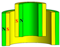 | OUT ← IN ← | ||
| Axial–axialmagnetization | Type II | 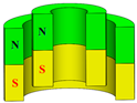 | OUT ↑ IN ↑ | ||
| Perpendicular magnetization (radial–axial) | Type III | 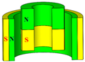 | OUT → IN ↑ | ||
| Perpendicular magnetization (axial–radial) | Type IV | 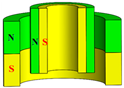 | OUT ↑ IN → |
| Type | All Denotations | Magnetic Force | Stiffness |
|---|---|---|---|
| Type I | OUT ← IN ← OUT ← IN → OUT → IN ← OUT → IN → | ||
| Type II | OUT ↑ IN ↑ OUT ↑ IN ↓ OUT ↓ IN ↑ OUT ↓ IN ↓ | ||
| Type III | OUT → IN ↑ OUT → IN ↓ OUT ← IN ↑ OUT ← IN ↓ | ||
| Type IV | OUT ↑ IN → OUT ↑ IN ← OUT ↓ IN → OUT ↓ IN ← |
| Symbol | Physical Meaning | Unit |
|---|---|---|
| The magnetic-field vector | − | |
| The residual flux density of the inner magnetic ring | T | |
| The residual flux density of the outer magnetic ring | T | |
| The axial force between the surface and the surface | N | |
| The half-height of the inner magnetic ring | m | |
| The half-height of the outer magnetic ring | m | |
| The surface current density vector | − | |
| The surface current density of surface 1 | A/m2 | |
| The surface current density of surface 1′ | A/m2 | |
| The surface current density of surface 3 | A/m2 | |
| The surface current density of surface 3′ | A/m2 | |
| The unit normal vector | − | |
| The inside radius of the inner magnetic ring | m | |
| Theoutside radius of the inner magnetic ring | m | |
| The inside radius of the outer magnetic ring | m | |
| Theoutside radius of the outer magnetic ring | m | |
| The radius of the Q point | m | |
| The radius of the P point | m | |
| The vector product | − | |
| The permeability of the vacuum | V⋅s/(A⋅m) | |
| The included angles between Q and the axis | rad | |
| The included angles between P and the axis | rad |
| Parameter | ||||||
| Value | 10 mm | 17.5 mm | 22.5 mm | 30 mm | 10 mm | 10 mm |
| Parameter | |||||
| Value | 10 mm | 17.5 mm | 22.5 mm | 30 mm | 5 mm |
Disclaimer/Publisher’s Note: The statements, opinions and data contained in all publications are solely those of the individual author(s) and contributor(s) and not of MDPI and/or the editor(s). MDPI and/or the editor(s) disclaim responsibility for any injury to people or property resulting from any ideas, methods, instructions or products referred to in the content. |
© 2025 by the authors. Licensee MDPI, Basel, Switzerland. This article is an open access article distributed under the terms and conditions of the Creative Commons Attribution (CC BY) license (https://creativecommons.org/licenses/by/4.0/).
Share and Cite
Chen, Z.; Zhang, Y.; Xiong, Y.; Wang, A. Analytical Investigations of Nonlinear Stiffness Characteristics of Halbach-Cylinder Magnetic Springs for Heavy-Load Capacity. Appl. Sci. 2025, 15, 5099. https://doi.org/10.3390/app15095099
Chen Z, Zhang Y, Xiong Y, Wang A. Analytical Investigations of Nonlinear Stiffness Characteristics of Halbach-Cylinder Magnetic Springs for Heavy-Load Capacity. Applied Sciences. 2025; 15(9):5099. https://doi.org/10.3390/app15095099
Chicago/Turabian StyleChen, Zhongsheng, Yangyi Zhang, Yeping Xiong, and Ankang Wang. 2025. "Analytical Investigations of Nonlinear Stiffness Characteristics of Halbach-Cylinder Magnetic Springs for Heavy-Load Capacity" Applied Sciences 15, no. 9: 5099. https://doi.org/10.3390/app15095099
APA StyleChen, Z., Zhang, Y., Xiong, Y., & Wang, A. (2025). Analytical Investigations of Nonlinear Stiffness Characteristics of Halbach-Cylinder Magnetic Springs for Heavy-Load Capacity. Applied Sciences, 15(9), 5099. https://doi.org/10.3390/app15095099