Article

Novel Fiber Bragg Grating Sensing Structure for Simultaneous Measurement of Inclination and Water Level

Department of Electro-Optical Engineering, National Taipei University of Technology, Taipei 10608, Taiwan
*
Author to whom correspondence should be addressed.
Appl. Sci. 2025, 15(9), 4819; https://doi.org/10.3390/app15094819
Submission received: 24 March 2025 / Revised: 20 April 2025 / Accepted: 22 April 2025 / Published: 26 April 2025
(This article belongs to the Special Issue Advanced Optical-Fiber-Related Technologies)

Abstract

:
In the context of significant climate change, monitoring inclination, water levels, and temperatures in public buildings and surrounding environments is sensible. This paper presents a pair of fiber Bragg grating (FBG) subsidence sensor systems designed to simultaneously measure tilt and water levels and explore the system’s potential to detect temperature variations. The configuration of the FBG subsidence sensor is intentionally skewed to enhance measurement sensitivity. The system is capable of concurrently detecting a 0.5 cm variation in water level and a 0.424° change in tilt, with tilt measurements spanning from −1.696° to 1.696°. Furthermore, the measurement system can be integrated with free-space optics (FSO), which is anticipated to address the challenges associated with installing fiber optic cables. Consequently, the proposed innovative FBG sensor system can measure multiple parameters using fewer sensors, thereby improving sensing capacity and cost-efficiency.

1. Introduction

Global extreme climatic events such as hurricanes, floods, and heat waves present significant challenges to both human life and the economy. The monitoring of water levels and the structural integrity of critical public facilities and infrastructure is essential for the prevention and mitigation of such disasters. Fiber optic sensors are particularly advantageous as they are power-free, compact in design, possess long operational lifespans, and are resistant to electromagnetic interference [1]. Additionally, they are highly sensitive and capable of measuring a wide range of physical parameters [2,3,4,5]. These characteristics render fiber optic sensors an optimal choice for monitoring efforts toward achieving net-zero carbon emissions.
Recent advancements in fiber optic sensors for liquid level or hydrological-related measurement have garnered significant attention [6,7,8,9,10,11,12,13,14,15,16,17,18,19,20], attributed to their numerous advantages. However, existing research predominantly addresses the measurement of a singular liquid level parameter. In practical applications, variables such as the liquid’s refractive index, temperature fluctuations, or the inclination of the monitoring structure may compromise this focus. Fiber optic interferometer sensors exhibit excellent measurement resolution, wide-band measurability [21,22,23,24], and the capacity to assess multiple parameters [25,26,27] simultaneously. However, due to the inherent complexity of the spectrum, employing multiple fiber optic interferometer sensors for concurrent measurements can often present significant challenges. Distributed fiber optic sensors possess the capability to measure multiple sites and various parameters simultaneously at a single location [28,29,30,31]. However, it is important to note that these sensors are typically more expensive and may not provide a cost-effective solution for measurements over small areas.
Standard FBG sensors can be configured in arrays to provide measurements akin to those obtained through distributed fiber optic sensing and can be effectively integrated with FSO to address cable routing challenges [32,33]. When FSO technology is integrated with sensors in applications where optical communication over distances of several hundred meters is feasible [34,35]. Commercially available FSO systems can achieve ranges of several kilometers or more, demonstrating their capability to function effectively even under adverse weather conditions [36]. This resilience highlights the utility of FSO technology in a diverse range of applications requiring reliable data transmission across considerable distances.
The liquid level measurement technique founded on the Archimedean buoyancy principle enables FBG sensors to accurately gauge liquid levels through a stretching mechanism [6]. This approach circumvents the influence of refractive index variations that may occur when the sensor comes into contact with the liquid [6]. Furthermore, intensity-based measurement sensors are often susceptible to variations in light source power; in contrast, FBG-based sensors exhibit resilience to such fluctuations [6]. By utilizing the center wavelength of the FBG sensor as a reference point, a single FBG is capable of simultaneously measuring both vibration and temperature [37]. However, simultaneous measurement of strain and temperature is not feasible unless spectral interrogation techniques are implemented in lieu of relying solely on the center wavelength value of the FBG [38].
In Archimedean buoyancy principle-based FBG subsidence sensor applications, two physical quantities, specifically changes in water level and tilt, are measured through the degree of stretching of the FBG indicated by the center wavelength. Consequently, the main limitation of FBG sensor measurements is that additional sensors must be arranged to measure more than two physical quantities simultaneously, owing to the same mechanism for FBG spectrum variation of these quantities. Nonetheless, it is important to note that FBG sensors retain significant potential for multi-site measurement applications within compact measurement environments. Moreover, the investigation of FBG subsidence sensors utilizing conventional FBGs for the simultaneous measurement of multiple parameters has not been conducted.
The primary distinction between the current tilt measurement study and the similar previous study [39] lies in the following point: the prior research utilized only two FBGs to ascertain both the tilt angle and the tilt direction. This study explores a modular system comprising two FBG subsidence sensors designed for the simultaneous measurement of water level and inclination while also investigating the feasibility of concurrently measuring various water temperatures. It is important to clarify that the upper limit of the measurement range and the measurement sensitivity of water level and tilt are not the primary focus of this study. Concentrating on these aspects would shift attention towards the design of sensor packaging rather than the measurement of multiple parameters. Furthermore, the FBG subsidence sensors were skewed in deployment to enhance the sensitivity of tilt measurements. Additionally, the measurement system can be integrated with the FSO, thereby potentially increasing the system’s flexibility for practical applications. Consequently, this study contributes to the cost optimization and efficacy of related monitoring and measurement processes.

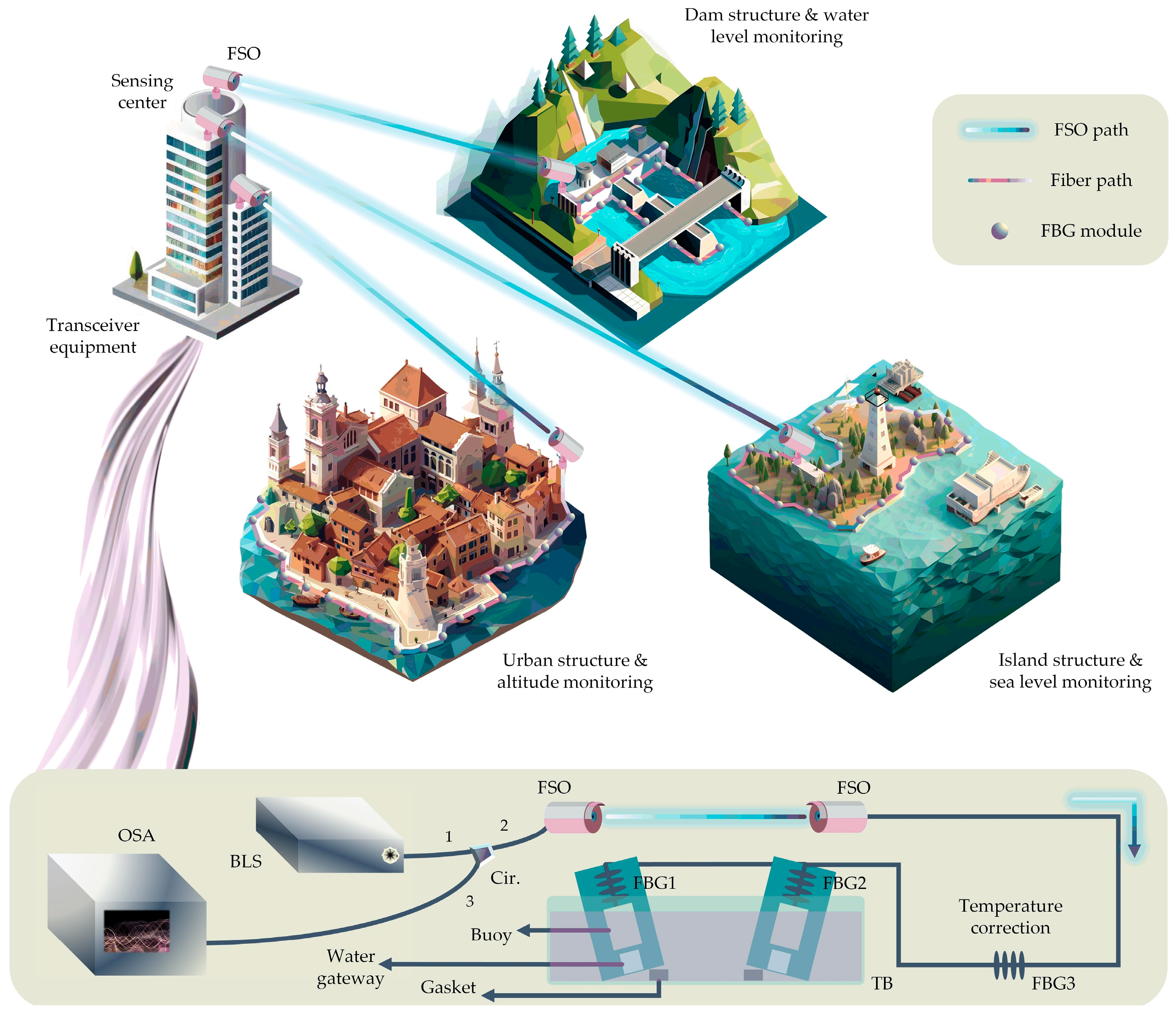
2. Experimental Setup

The upper section of Figure 1 illustrates the potential applications of utilizing FBG subsidence sensors in conjunction with FSOs to measure water levels and tilt. Such applications are pertinent in various contexts, including dams, offshore regions, and sea islands, among others. The optical coupler is vital in enhancing the multi-sensory pathways, allowing for the strategic distribution of multiple FBG sensing networks across various locations within measurement applications. When the density of FBG sensors increases, challenges may arise due to wavelength overlap or interference, which can adversely impact the accuracy of wavelength interrogation results. To address this issue, implementing machine learning techniques is recommended to effectively resolve the wavelength interrogation challenges [40]. The primary framework of the experiment is illustrated in the lower section of Figure 1. For real applications, the sensing signal transceiver must be strategically positioned at the sensing center. Through FSO, the optical signal can be captured by the FBG sensor located at the measurement point. To facilitate experimental procedures and enhance operational efficiency, the broadband light source (BLS) emits the optical signal via an optical circulator (Cir.) to the 2 m FSO link in the lab instead of the outdoor corresponding scene. This is subsequently connected to the FBG array sensors for measurement purposes. The sensed signal is then routed back to the optical circulator and directed to the optical spectrum analyzer (OSA) for comprehensive signal observation. The FBG sensing module comprises 3 FBGs; two FBG subsidence sensors are used to measure the water level and tilt simultaneously, and the remaining FBG is used to correct air temperature change. The FBG subsidence sensor consists of a conventional FBG that supports a buoy [41]. Both the FBG and the buoy are contained within a hollow cylindrical bottle, which is designed with an opening to facilitate water flow in and out. Consequently, variations in water level, or changes induced by the tilting of the cylindrical bottle, will affect the buoy’s positioning. This, in turn, will stretch the FBG, leading to alterations in the center wavelength of the FBG. For the measurement conditions, FBG subsidence sensors are placed in the temperature bath (TB) to control the water level and temperature for customization of measurement conditions. The tilted measurement setup is made by placing a gasket under the leftmost or rightmost side of the rectangular TB. The tilting of the TB tilts the FBG subsidence sensors, but the water surface remains flat. The length of the TB is 32 cm, and the thickness of the gasket is 2.4 mm, so the calculation shows that each additional gasket used will increase the tilt angle by 0.424°. To enhance measurement sensitivity, a gasket with a thickness of 1.6 mm has been positioned beneath the FBG subsidence sensors. Furthermore, the two FBG subsidence sensors have been strategically placed at opposing ends of the TB apparatus. This arrangement ensures that, in instances of TB tilt, there is a pronounced water level difference between the two sensors, thereby optimizing the accuracy of the measurements. Incidentally, the equipment’s brand and model are respectively affiliated with UNICE Inc. (Taoyuan, Taiwan) NA0101 for BLS; Thorlabs Inc. (Newton, NJ, USA) F810FC-1550 for FSO; Citpo Technologies Inc. (Taipei, Taiwan) for the FBG subsidence sensor; and Anritsu Inc. (Atsugi, Japan) MS9740A for OSA.

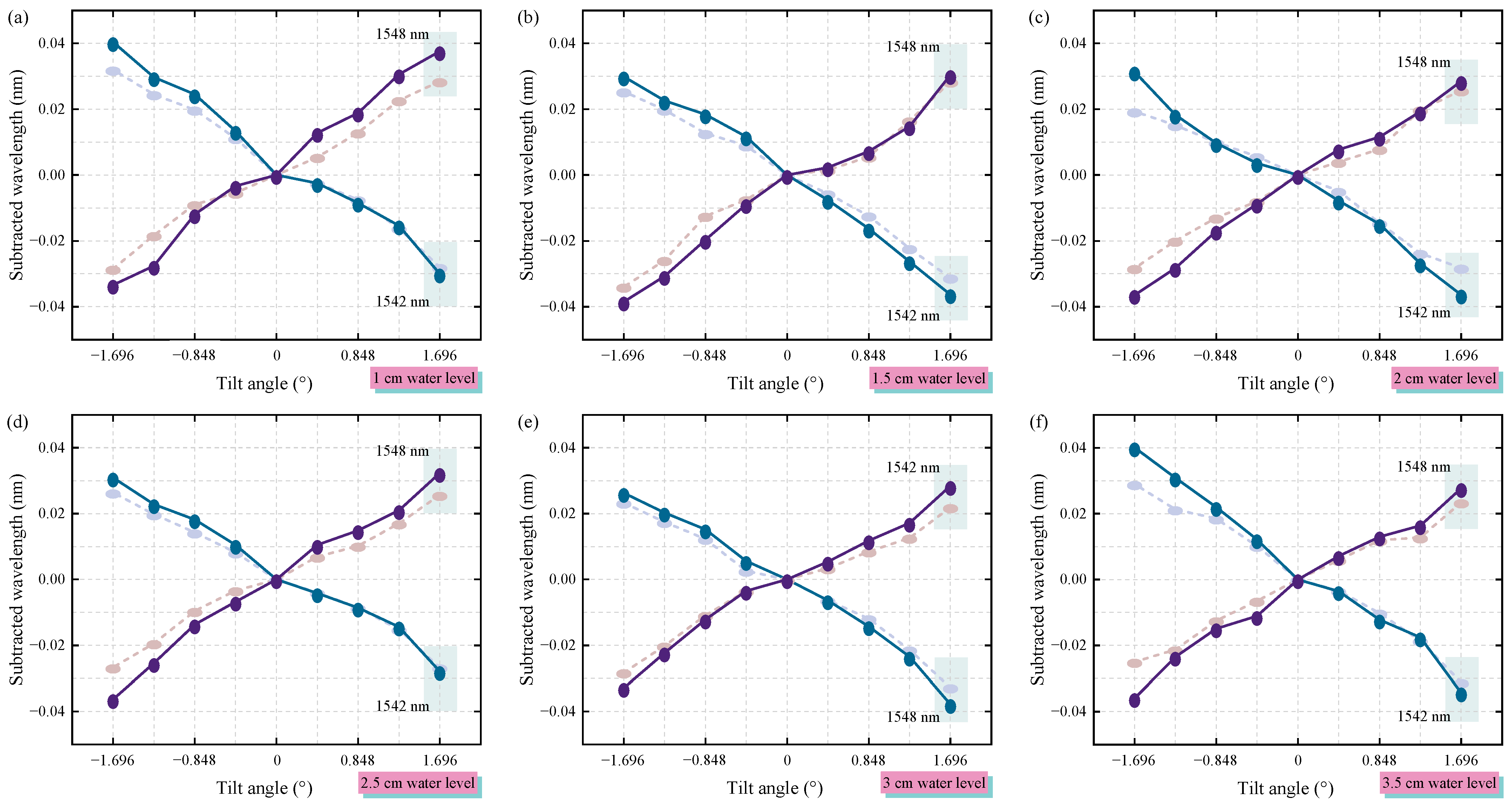
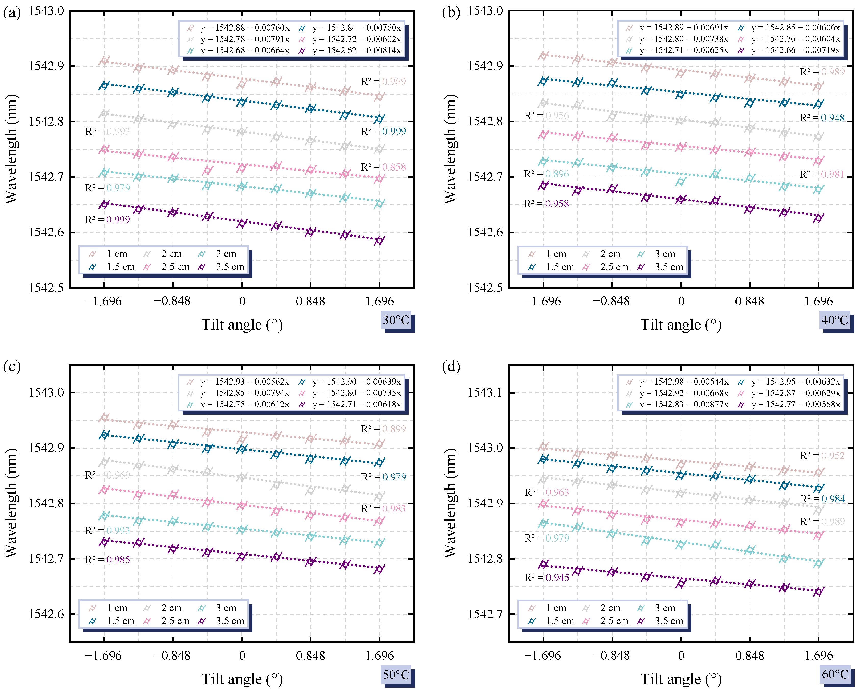
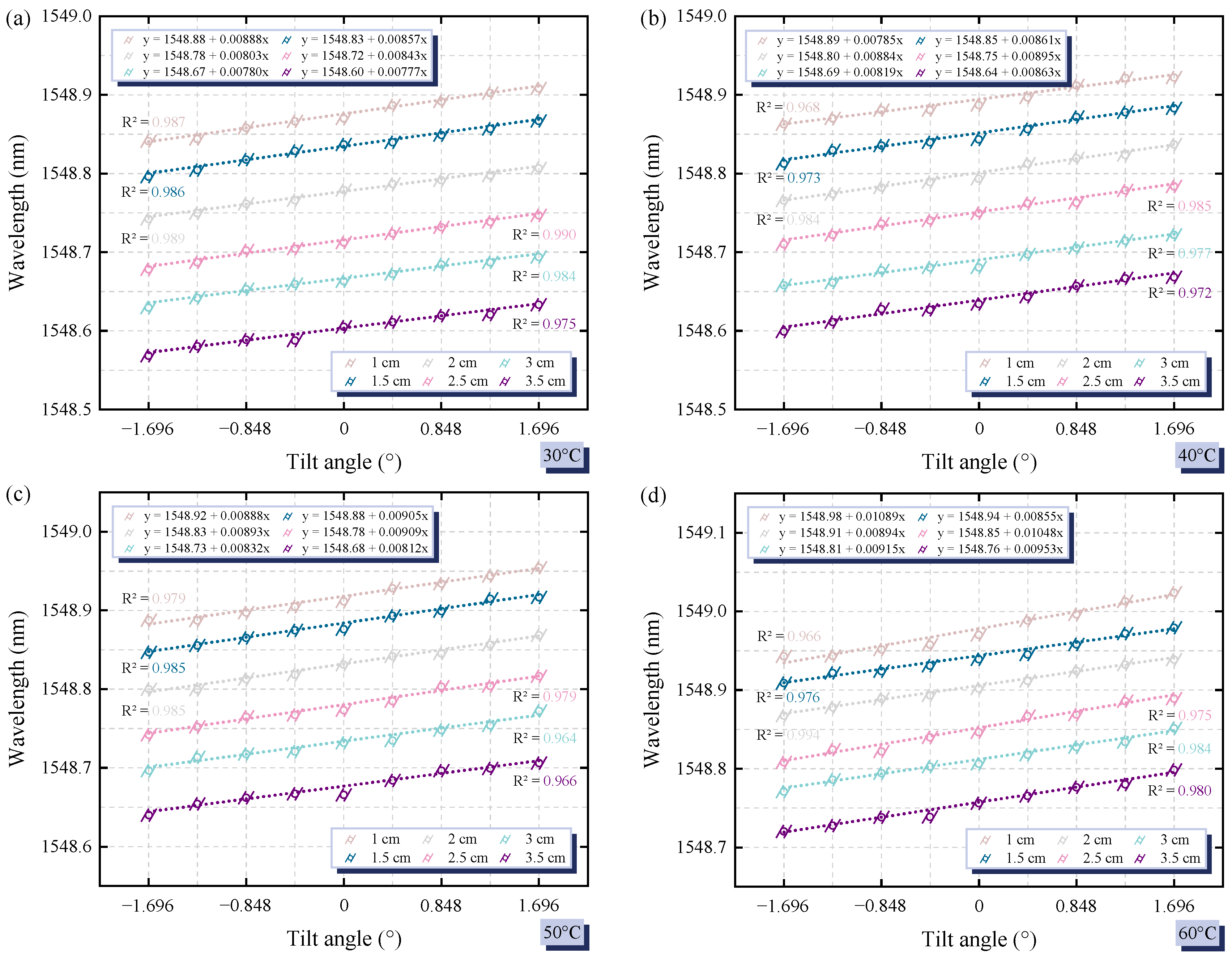
3. Experimental Results

As previously stated, variations in water levels or angular dip result in shifts in the position of the buoys on the FBG subsidence sensors. These shifts subsequently induce strain on the FBGs, leading to alterations in their center wavelengths. Consequently, this mechanism allows for the understanding that, at a consistent water level, variations in the inclination angle of FBG subsidence sensors can alter the buoy’s submerged surface area. This, in turn, affects the buoyancy, leading to the FBG’s elongation. To enhance measurement resolution, it is advisable to increase the immersion area variation of the buoy whenever the inclination angle varies. As previously indicated, incorporating a gasket at the base of the FBG subsidence sensor can augment its sensitivity. This enhancement is attributed to the buoy’s rectangular design; when the FBG subsidence sensor is positioned at an angle, it results in a greater alteration of the buoy’s immersed area with each change in tilt, in contrast to a vertically oriented FBG subsidence sensor.
The experimental results are shown in Figure 2, in which the initial wavelength of FBG1 is 1548 nm; the initial wavelength of FBG2 is 1542 nm, so the overall tilting of the TB to the right, such as 0.424°, 0.848°, 1.272°, and 1.696°, will lead to a decrease in the water level at the FBG1, and thus the buoyancy force decreases, so that the FBG wavelength is subjected to long wavelength drift. Conversely, a leftward tilt of the TB will cause the water level at FBG1 to rise and increase the buoyancy, resulting in a reduction of the strain on the FBG and a drift to a shorter wavelength. On the other hand, FBG2 is located on the right side of TB, so when TB is tilted left or right, the water level at FBG2 changes in the opposite direction to that at FBG1, which makes the wavelength drift direction of FBG2 opposite to that of FBG1. Figure 2a–f sequentially presents the tilt measurements at water levels of 1 cm, 1.5 cm, 2 cm, 2.5 cm, 3 cm, and 3.5 cm. It is observed that the drift trends of the FBG wavelengths exhibit consistency across different water levels during the tilting process. A crucial aspect of Figure 2 is that the solid line indicates the FBG wavelength drift observed when the FBG subsidence sensors are installed at an oblique angle. In contrast, the drift represented by the dotted line corresponds to the FBG wavelength changes when the sensors are positioned normally. The measurement results affirm the initial hypothesis, demonstrating that the inclined placement of FBG subsidence sensors enhances measurement sensitivity. Furthermore, the drift in FBG wavelength appears to be a somewhat nonlinear pattern, especially at low water levels. This is because in low water, the buoys are in contact with less water, and the FBG subsidence sensors are placed on both sides of the TB rather than in the center; therefore, when the buoys are tilted left and right at the same water level, the buoys are buoyed differently, thus causing the drift of the FBG wavelength to be not so linear.
The experimental results presented in Figure 2 indicate that the skewed FBG subsidence sensors exhibit greater wavelength variation and enhanced sensitivity. Consequently, subsequent experiments will measure skewed readings at various water levels and temperatures, adhering to the experimental configuration depicted in Figure 1. Figure 3 presents the drift results of the FBG wavelength at 1542 nm, evaluated under varying water temperatures and levels. Given that fluctuations in water temperature also influence the buoyancy of the buoys, it is essential to examine the measurements across different thermal conditions. The water temperatures in Figure 3 correspond to 30 °C, 40 °C, 50 °C, and 60 °C in Figure 3a–d and the water level and inclination settings are consistent with those in Figure 2. The data presented in Figure 3 indicate that, irrespective of water temperature, an increase in water level results in a corresponding reduction in wavelength. This phenomenon can be attributed to the amplification of buoyancy, which consequently decreases the strain experienced by the FBG. In addition, 1542 nm of the FBG2 wavelength is placed on the right side of TB, so TB tilted to the right will cause the water level to rise, i.e., buoyancy will increase so that the FBG wavelength will drift towards the shorter wavelengths, while TB tilted to the left will have the opposite effect. Corresponding to the results in Figure 2, the wavelength drift is linear with respect to the angle of inclination. Furthermore, an increase in water temperature is observed to cause a significant drift of the FBG wavelength towards longer wavelengths. As the temperature of the water rises, the buoyancy typically declines due to a decrease in water density. Consequently, if the buoy volume of discharged water remains constant, the overall buoyancy of the water will diminish.
As previously noted, the necessity of concurrently measuring water levels and incline variations necessitates the deployment of two FBGs. This requirement arises because the right-leaning condition observed at low water levels may yield wavelength readings for the FBGs that are indistinguishable from those generated under the left-leaning condition at elevated water levels, as illustrated in Figure 3. Consequently, employing two FBGs for measurements can effectively eliminate potential confusion regarding the parameter signals and address this limitation. Figure 4a–d illustrate the wavelength measurements of FBG1, which is based on a reference wavelength of 1548 nm. The measurement setups utilized are identical to those presented in Figure 3a–d. A notable distinction is that FBG1 is positioned on the left side of the TB. Consequently, when the TB is inclined to the left or right, the resulting changes in the water level exhibit an inverse relationship with those observed in FBG2. Therefore, the most significant finding depicted in Figure 4 is that the drift tendency of the FBG wavelength is precisely opposite to that illustrated in Figure 3. By recording the wavelength readings from both FBG1 and FBG2, it is possible to concurrently ascertain the water level and tilt parameters. The findings presented in Figure 3 and Figure 4 indicate that an increase in temperature results in a drift of the FBG towards longer wavelengths. However, while measuring both water level and tilt using two separate FBG sensors is feasible, conducting concurrent measurements of water temperature with the same two FBGs poses significant challenges. This difficulty arises from the fact that the wavelength drift of the FBG, attributed to buoyancy changes stemming from variations in water temperature, is minimal. Furthermore, a more complex consideration is that the salinity of the water influences its density, subsequently affecting buoyancy. It is advisable to incorporate additional sensors to accurately measure water temperature, ensuring that the concurrent measurements of water level and inclination are not compromised by variations in temperature and salinity. Notably, it is feasible to measure either water level and temperature or inclination and temperature simultaneously, provided that salinity remains constant. The feasibility of concurrent measurement of water level, tilt, and temperature is contingent upon a significant temperature differential in the water utilized for the measurement applications, specifically exceeding 30 °C. It is important to note that the data corresponding to the shortest wavelength of subfigure a and the longest wavelength of subfigure d in Figure 3 and Figure 4 do not overlap with other datasets. Thus, under these exceptional conditions, it is possible to accurately obtain the aforementioned measurements simultaneously. It is also worth mentioning that the wavelength of FBG3, utilized for calibration to adjust for wavelength measurement deviations induced by changes in air temperature, is consistently maintained at 1544 nm. Consequently, there is no requirement to compensate for wavelength changes due to fluctuations in air temperature in the context of this experiment.
As previously discussed, the difference in buoyancy of the buoy at the same water level when tilted to the left or right results in a non-linear shift of the FBG wavelength. This phenomenon arises from the tilting of the FBG subsidence sensors; however, it is also primarily attributable to the geometric configuration of both the water container and the buoy utilized in the FBG subsidence sensor. Achieving a consistent FBG wavelength shift for identical tilt angle changes proves to be challenging and impractical, as it necessitates consideration of varying water levels and temperatures. Consequently, it is difficult to design a water container and buoy with an appropriate shape and mass that would ensure a uniform buoyancy change for every equal tilt angle variation, particularly when accounting for the diverse conditions presented by different water levels and temperatures. Consequently, a slight nonlinear wavelength drift is inevitable and may indirectly influence measurement accuracy. However, this challenge is not insurmountable. In comparison to a previous similar investigation [39], the sensitivity of the tilt measurement within this framework still presents opportunities for optimization. These enhancements primarily hinge on the interplay between the design of the buoy and the configuration of the water container. For the existing scheme, if the size of the water vessel, the volume of the buoy, and the length of the TB are increased, the measurement sensitivity can be improved theoretically. Therefore, as measurement sensitivity improves, the resultant increase in the reflected FBG wavelength drift will diminish the likelihood of misinterpreting the measured tilt angle or water level, thereby fostering greater measurement accuracy.

4. Conclusions

This paper presents a novel pair of FBG subsidence sensors, which are designed to measure left and right tilt and changes in water levels simultaneously. The sensors are uniquely skewed and configured in opposing directions, facilitating the collection of accurate data on slope variations and water level fluctuations. The sensing system is capable of resolving at least 0.424° of inclination and 0.5 cm of water level change, while also being able to detect variations in water temperature when either water level or inclination measurements are conducted independently. Furthermore, the proposed measurement system is compatible with FSO, streamlining the system by reducing the maintenance and installation costs typically associated with fiber optic cabling. This innovative FBG sensor system enables the measurement of multiple parameters with a reduced number of sensors, significantly enhancing sensing capabilities and maximizing cost efficiency.

Author Contributions

Conceptualization, C.-K.Y.; methodology, C.-K.Y., Y.-J.C. and Y.-C.X.; data curation, Y.-C.X. and C.-K.Y.; model validation, Y.-J.C. and C.-K.Y.; formal analysis, C.-K.Y., Y.-J.C. and P.K.; investigation, C.-K.Y., Y.-J.C., Y.-C.X., P.K. and P.-C.P.; visualization: C.-K.Y.; writing—original draft preparation: C.-K.Y.; writing—review and editing: C.-K.Y.; supervision, P.-C.P. All authors have read and agreed to the published version of the manuscript.

Funding

This work was supported by the National Science and Technology Council, Taiwan, under Grant NSTC 112-2221-E-027-076-MY2.

Institutional Review Board Statement

Not applicable.

Informed Consent Statement

Not applicable.

Data Availability Statement

The data presented in this study are available in this article.

Conflicts of Interest

The authors declare no conflicts of interest.

References

  1. Song, J.; Leng, J.; Li, J.; Wei, H.; Li, S.; Wang, F. Application of Acoustic Emission Technique in Landslide Monitoring and Early Warning: A Review. Appl. Sci. 2025, 15, 1663. [Google Scholar] [CrossRef]
  2. Leal-Junior, A.; Silva, J.; Macedo, L.; Marchesi, A.; Morau, S.; Valentino, J.; Valentim, F.; Costa, M. The Role of Optical Fiber Sensors in the New Generation of Healthcare Devices: A Review. Sens. Diagn. 2024, 3, 1135–1158. [Google Scholar] [CrossRef]
  3. Cięszczyk, S.; Panas, P.; Skorupski, K.; Kida, M. Fibre Bragg Grating Wavelength Shift Demodulation with Filtering and Enhancement of Spectra by Simple Nonlinear Signal Processing. Appl. Sci. 2025, 15, 3384. [Google Scholar] [CrossRef]
  4. Leal-Junior, A.; Silveira, M.; Macedo, L.; Frizera, A.; Marques, C. Polarization-Assisted Multiparameter Sensing Using a Single Fiber Bragg Grating. Opt. Fiber Technol. 2024, 84, 103775. [Google Scholar] [CrossRef]
  5. Mandal, H.N.; Sidhishwari, S. Apodized Chirped Fiber Bragg Grating for Measuring the Uniform and Non-Uniform CharacTeristics of Physical Parameters. Measurement 2025, 240, 115606. [Google Scholar] [CrossRef]
  6. Ramos, C.C.; Preizal, J.; Hu, X.; Caucheteur, C.; Woyessa, G.; Bang, O.; Rocha, A.M.; Oliveira, R. High Resolution Liquid Level Sensor Based on Archimedes’ Law of Buoyancy Using Polymer Optical Fiber Bragg Gratings. Measurement 2025, 252, 117368. [Google Scholar] [CrossRef]
  7. de Almeida, G.G.; Barreto, R.C.; Seidel, K.F.; Kamikawachi, R.C. A Fiber Bragg Grating Water Level Sensor Based on the Force of Buoyancy. IEEE Sens. J. 2019, 20, 3608–3613. [Google Scholar] [CrossRef]
  8. Rosolem, J.B.; Dini, D.C.; Penze, R.S.; Floridia, C.; Leonardi, A.A.; Loichate, M.D.; Durelli, A.S. Fiber Optic Bending Sensor for Water Level Monitoring: Development and Field Test: A Review. IEEE Sens. J. 2013, 13, 4113–4120. [Google Scholar] [CrossRef]
  9. He, R.; Teng, C.; Kumar, S.; Marques, C.; Min, R. Polymer Optical Fiber Liquid Level Sensor: A Review. IEEE Sens. J. 2021, 22, 1081–1091. [Google Scholar] [CrossRef]
  10. Lee, H.K.; Choo, J.; Kim, J. Multiplexed Passive Optical Fiber Sensor Networks for Water Level Monitoring: A Review. Sensors 2020, 20, 6813. [Google Scholar] [CrossRef]
  11. Lee, H.K.; Kim, Y.; Park, S.; Kim, J. Passive IoT Optical Fiber Sensor Network for Water Level Monitoring with Signal Processing of Feature Extraction. Electronics 2023, 12, 1823. [Google Scholar] [CrossRef]
  12. Dejband, E.; Tan, T.H.; Yao, C.K.; Chang, E.M.; Peng, P.C. Enhancing Multichannel Fiber Optic Sensing Systems with IFFT-DNN for Remote Water Level Monitoring. Sensors 2024, 24, 4903. [Google Scholar] [CrossRef]
  13. Lee, H.K.; Choo, J.; Shin, G.; Kim, J. Long-Reach DWDM-Passive Optical Fiber Sensor Network for Water Level Monitoring of Spent Fuel Pool in Nuclear Power Plant. Sensors 2020, 20, 4218. [Google Scholar] [CrossRef]
  14. Pereira, K.; Coimbra, W.; Lazaro, R.; Frizera-Neto, A.; Marques, C.; Leal-Junior, A.G. FBG-Based Temperature Sensors for Liquid Identification and Liquid Level Estimation Via Random Forest. Sensors 2021, 21, 4568. [Google Scholar] [CrossRef] [PubMed]
  15. Schenato, L. A Review of Distributed Fibre Optic Sensors for Geo-Hydrological Applications. Appl. Sci. 2017, 7, 896. [Google Scholar] [CrossRef]
  16. Shangguan, M.; Yang, Z.; Shangguan, M.; Lin, Z.; Liao, Z.; Guo, Y.; Liu, C. Remote Sensing Oil in Water with an All-Fiber Underwater Single-Photon Raman Lidar. Appl. Opt. 2023, 62, 5301–5305. [Google Scholar] [CrossRef]
  17. Li, P.; Yan, H.; Zhang, H. Highly Sensitive Liquid Level Sensor Based on an Optical Fiber Michelson Interferometer with Core-Offset Structure. Optik 2018, 171, 781–785. [Google Scholar] [CrossRef]
  18. Wang, S.; Yang, Y.; Zhang, L.; Mohanty, L.; Jin, R.B.; Wu, S.; Lu, P. High-Precision Fiber Optic Liquid Level Sensor Based on Fast Fourier Amplitude Demodulation in a Specific Range of Spectrum. Measurement 2022, 187, 110326. [Google Scholar] [CrossRef]
  19. Martins, J.; Diaz, C.A.; Domingues, M.F.; Ferreira, R.A.; Antunes, P.; Andre, P.S. Low-Cost and High-Performance Optical Fiber-Based Sensor for Liquid Level Monitoring. IEEE Sens. J. 2019, 19, 4882–4888. [Google Scholar] [CrossRef]
  20. Diaz, C.A.; Leal-Junior, A.; Marques, C.; Frizera, A.; Pontes, M.J.; Antunes, P.F.; Andre, P.S.; Ribeiro, M.R. Optical Fiber Sensing for Sub-Millimeter Liquid-Level Monitoring: A Review. IEEE Sens. J. 2019, 19, 7179–7191. [Google Scholar] [CrossRef]
  21. Lee, C.L.; Yeh, C.Y.; Jiang, Y.X. Effective Liquid-filled Leaky-Guided Fiber Mach-Zehnder Interferometer with a Side-Polished Fiber. IEEE Sens. J. 2025, 25, 9681–9688. [Google Scholar] [CrossRef]
  22. Zhu, K.; Ren, S.; Li, X.; Liu, Y.; Li, J.; Zhang, L.; Wang, M. Sub-Micron Two-Dimensional Displacement Sensor Based on a Multi-Core Fiber. Photonics 2024, 11, 1073. [Google Scholar] [CrossRef]
  23. Noori, N.F.; Mansour, T.S. A Review of Recently Optical Hybrid Optical Fiber Interferometers. J. Opt 2025, 1–14. [Google Scholar] [CrossRef]
  24. Wei, Y.; Yang, M.; Shao, Y.; Liu, C.; Ren, P.; Zhang, Z.; Liu, Z. Asymmetric Coated Direction Recognition Fiber Optic Interferometric Curvature Sensor. J. Light. Technol. 2025, 1–6. [Google Scholar] [CrossRef]
  25. Lu, C.; Su, J.; Dong, X.; Sun, T.; Grattan, K.T. Simultaneous Measurement of Strain and Temperature with a Few-Mode Fiber-Based Sensor. J. Light. Technol. 2018, 36, 2796–2802. [Google Scholar] [CrossRef]
  26. Lei, X.; Dong, X.; Lu, C.; Sun, T.; Grattan, K.T. Underwater Pressure and Temperature Sensor Based on a Special Dual-Mode Optical Fiber. IEEE Access 2020, 8, 146463–146471. [Google Scholar] [CrossRef]
  27. Duan, S.; Wang, W.; Xiong, L.; Wang, B.; Liu, B.; Lin, W.; Zhang, H.; Liu, H.; Zhang, X. All In-Fiber Fabry–Pérot Interferometer Sensor Towards Refractive Index and Temperature Simultaneous Sensing. Opt. Laser Technol. 2025, 180, 111551. [Google Scholar] [CrossRef]
  28. Dang, Y.; Zhao, Z.; Wang, X.; Liao, R.; Lu, C. Simultaneous Distributed Vibration and Temperature Sensing Using Multicore Fiber. IEEE access 2019, 7, 151818–151826. [Google Scholar] [CrossRef]
  29. Lu, L.; Yong, M.; Wang, Q.; Bu, X.; Gao, Q. A Hybrid Distributed Optical Fiber Vibration and Temperature Sensor Based on Optical Rayleigh and Raman Scattering. Opt. Commun. 2023, 529, 129096. [Google Scholar] [CrossRef]
  30. Zhou, Z.; Tian, L.; Han, Y.; Yang, X.; Liao, F.; Zhang, D.; Sha, Y.; Feng, X.; Zhu, J.; Zheng, X.; et al. Distributed Vibration and Temperature Simultaneous Sensing Using One Optical Fiber. Opt. Commun. 2021, 487, 126801. [Google Scholar] [CrossRef]
  31. Yao, C.K.; Lin, T.C.; Chen, H.M.; Hsu, W.Y.; Manie, Y.C.; Peng, P.C. Inclination Measurement Adopting Raman Distributed Temperature Sensor. IEEE Sens. J. 2023, 23, 22543–22555. [Google Scholar] [CrossRef]
  32. Kanwal, F.; Atieh, A.; Ghafoor, S.; Haq, A.U.; Qureshi, K.K.; Aziz, I.; Mirza, J. Remote Monitoring of Sleep Disorder Using FBG Sensors and FSO Transmission System Enabled Smart Vest. Eng. Res. Express 2024, 6, 025337. [Google Scholar] [CrossRef]
  33. Sadik, S.A. Leveraging Fiber Bragg Grating Sensors for Enhanced Security in Smart Grids. In 5G and Fiber Optics Security Technologies for Smart Grid Cyber Defense; IGI Global: Hershey, PA, USA, 2024; pp. 259–288. [Google Scholar]
  34. Zhang, Q.; Yu, J.; Long, J.; Wang, C.; Chen, J.; Lu, X. A Hybrid RF/FSO Transmission System Based on a Shared Transmitter. Sensors 2025, 25, 2021. [Google Scholar] [CrossRef]
  35. Syriopoulos, G.; Kyriazi, E.; Prousalidi, T.; Ntanos, A.; Stathis, A.; Kourelias, P.; Toumasis, P.; Zervos, H.; Giannoulis, G.; Poulopoulos, G.; et al. Co-Existence of SiPh Sensing Link and Real World Traffic over 100 m FSO link for 6G Deployments. IEEE Photonics Technol. Lett. 2025, 37, 9. [Google Scholar] [CrossRef]
  36. Yao, C.K.; Lin, H.P.; Cheng, C.L.; Chung, M.A.; Lin, Y.S.; Wu, W.B.; Chiang, C.W.; Peng, P.C. Fiber/Free-Space Optics with Open Radio Access Networks Supplements the Coverage of Millimeter-Wave Beamforming for Future 5G and 6G Communication. Fibers 2025, 13, 39. [Google Scholar] [CrossRef]
  37. Yao, C.K.; Kumar, P.; Liu, B.X.; Dehnaw, A.M.; Peng, P.C. Simultaneous Vibration and Temperature Real-Time Monitoring Using Single Fiber Bragg Grating and Free Space Optics. Appl. Sci. 2024, 14, 11099. [Google Scholar] [CrossRef]
  38. Choi, B.K.; Kim, J.S.; Ahn, S.; Cho, S.Y.; Kim, M.S.; Yoo, J.H.; Jeon, M.Y. Simultaneous Temperature and Strain Measurement in Fiber Bragg Grating Via Wavelength-Swept Laser and Machine Learning. IEEE Sens. J. 2024, 24, 27516–27524. [Google Scholar] [CrossRef]
  39. Chao, C.R.; Liang, W.L.; Liang, T.C. Design and Testing of a 2D Optical Fiber Sensor for Building Tilt Monitoring Based on Fiber Bragg Gratings. Appl. Syst. Innov. 2017, 1, 2. [Google Scholar] [CrossRef]
  40. Bogale, S.D.; Yao, C.K.; Manie, Y.C.; Zhong, Z.G.; Peng, P.C. Wavelength-Dependent Bragg Grating Sensors Cascade an Interferometer Sensor to Enhance Sensing Capacity and Diversification through the Deep Belief Network. Appl. Sci. 2024, 14, 7333. [Google Scholar] [CrossRef]
  41. Dejband, E.; Manie, Y.C.; Deng, Y.J.; Bitew, M.A.; Tan, T.H.; Peng, P.C. High Accuracy and Cost-Effective Fiber Optic Liquid Level Sensing System Based on Deep Neural Network. Sensors 2023, 23, 2360. [Google Scholar] [CrossRef]
Figure 1. The application vision and experimental setup of using FBG module to integrate with FSO to simultaneously measure inclination angle and water level.
Applsci 15 04819 g001
Figure 2. At varying water levels, FBG subsidence sensors have been deployed at both skewed positions (represented by solid line data) and standard positions (denoted by dashed line data) to monitor the wavelength drift resulting from tilting. The measurements correspond to the 30 °C water temperature with the following water levels: (a) 1 cm, (b) 1.5 cm, (c) 2 cm, (d) 2.5 cm, (e) 3 cm, and (f) 3.5 cm.
Applsci 15 04819 g002
Figure 3. The FBG wavelength shift results of the tilt measurements correspond to 1542 nm at different water levels. The temperature conditions for the water during the measurements were as follows: (a) 30 °C, (b) 40 °C, (c) 50 °C, and (d) 60 °C.
Applsci 15 04819 g003
Figure 4. The FBG wavelength shift results of the tilt measurements correspond to 1548 nm at different water levels. The temperature conditions for the water during the measurements were as follows: (a) 30 °C, (b) 40 °C, (c) 50 °C, and (d) 60 °C.
Applsci 15 04819 g004
Disclaimer/Publisher’s Note: The statements, opinions and data contained in all publications are solely those of the individual author(s) and contributor(s) and not of MDPI and/or the editor(s). MDPI and/or the editor(s) disclaim responsibility for any injury to people or property resulting from any ideas, methods, instructions or products referred to in the content.

