Article

Research on Hydraulic Fracturing Technology for Roof Stratigraphic Horizon in Coal Pillar Gob-Side Roadway

1
Shaanxi Bureau of State Mine Safety Supervision Bureau, Xi’an 710001, China
2
Inner Mongolia Limin Coal Char Co., CHN Energy Wuhai Energy Company, Ordos 016064, China
3
State Key Laboratory for Fine Exploration and Intelligent Development of Coal Resources, China University of Mining and Technology, Xuzhou 221116, China
4
Key Laboratory of Deep Coal Resource Mining of Ministry of Education, School of Mines, China University of Mining and Technology, Xuzhou 221116, China
*
Authors to whom correspondence should be addressed.
Appl. Sci. 2025, 15(9), 4759; https://doi.org/10.3390/app15094759
Submission received: 9 March 2025 / Revised: 10 April 2025 / Accepted: 16 April 2025 / Published: 25 April 2025

Abstract

:
The return roadway in Limin Coal Mine experiences strong mine pressure during the mining work of the I030902 working face, which poses potential safety hazards to production and management. Therefore, hydraulic fracturing is used to relieve pressure on the free coal pillar roof. Hydraulic fracture simulation tests using gelatin materials were conducted, and the propagation of the hydraulic fracturing cracks in gelatin simulating different key strata was obtained, which led to the design of the hydraulic fracturing used in the I030902 working face at Limin Coal Mine. According to the analysis of the on-site tests, after fracturing, the roof pressure decreased by 17.8%, the average pressure step distance reduced by 18.0%, the average daily rate of the roof and floor convergence decreased by 63.86%, and the average daily rate of the roof and floor convergence was reduced by 72.4%. Therefore, the feasibility of the hydraulic fracturing in weak structure formation in hard roof strata and roadway deformation control has been verified, providing a theoretical foundation and on-site date for the relief of free roadway roof pressure.

1. Introduction

In recent years, many researchers have conducted extensive work on using blasting to address and improve the free coal pillar [1]. In engineering projects, although the blasting method can solve the problem of mine pressure in most cases [2,3,4], it still has many limitations [5]: (1) blasting can damage the shaft and drift support, and the surrounding rock mass may suffer secondary impacts if the design is not appropriate for the project; (2) the impact of blasting may damage precision instruments, such as mine pressure detection equipment in intelligent working faces; (3) the toxic gases produced by blasting are harmful to employees and pose a threat to their safety; and (4) the preparation and application methods of CO2 fracturing blasting are complex, resulting in low construction efficiency.
Various methods, such as pre-splitting blasting [6,7], CO2 fracturing blasting [8,9,10], and static expansive agent fracturing [11,12,13], have been used to address and improve the free coal pillar and achieve significant results through on-site industrial tests. However, the research related to hydraulic fracturing in multi-layered regions is limited. The drilling observation results of the roof at the I030902 working face of Limin Coal Mine show that the roof is highly stratified, making it unsuitable for the aforementioned methods. Therefore, the following issues exist in the related domestic and international research:
There is a lack of theoretical and experimental basis for addressing and improving free coal pillar roadways. The experimental materials used in the related research are non-transparent materials [14], making it difficult to observe the propagation of the hydraulic fracturing cracks directly. Additionally, the double-seal packer is used to fracture the hard roof of the free coal pillar roadway, while both domestic and international laboratories cannot accurately replicate the actual on-site conditions [15].
Research on hydraulic fracturing in multi-layered regions is limited. Previous methods, such as pre-splitting blasting, CO2 fracturing blasting, static expansive agent fracturing, and directional long-hole hydraulic fracturing technology, are not suitable for application in Limin Coal Mine, where the roof is severely stratified, especially directional long-hole fracturing. Due to the single fracturing strata and excessive fracturing steps, directional long-hole fracturing cannot fully fracture the roof.
As a green, safe, and efficient technological method, hydraulic fracturing has already been successfully applied in the petroleum engineering field [16,17,18]. In recent years, the application of hydraulic fracturing technology in the coal mining industry has primarily focused on enhancing the permeability of coal seams by improving the caving ability of roof strata [19]. Hydraulic fracturing is a method that injects high-flow fluids into coal and rock strata to increase artificial fractures within the coal rock [20,21,22]. In the coal mining field, hydraulic fracturing technology has become an important approach to enhance the permeability of high-gas coal seams and increase coalbed methane production [23]. Specifically, in response to issues such as the difficulty of natural caving in thick and hard coal seam roofs in some mining areas and the frequent occurrence of rock burst disasters [24], hydraulic fracturing technology provides strong support for achieving green, safe, and efficient coal resource extraction [25].
Based on the micro-seismic monitoring results, two key induced fracture strata were identified in the overlying strata of the free narrow coal pillar: the siltstone layer located 24.65–33.65 m above the coal seam and the coarse-grained sandstone layer located 38.44–48.63 m above the 9−1 coal seam. There are few research studies on the theory and numerical simulation of irregular hydraulic crack propagation [26]. In this paper, laboratory experiments are used to study the crack steering process of non-directional hydraulic fracturing, which provides a basis for research on the trajectory of hydraulic crack development in two key layers. In order to simulate the preprocessing effect of the hydraulic fracturing in different key strata, hydraulic fracture simulation tests of gelatin materials will be conducted under the same stress environment and using a double-seal-type hole packer similar to that used in the field to obtain the propagation law of hydraulic fractures after non-directional initiation. The conclusions obtained will help to guide the field hydraulic fracturing test. Meanwhile, the on-site fracturing parameters are optimized, and the feasibility of hydraulic fracturing in alleviating the strong dynamic pressure caused by mining stress on the return roadway and controlling the deformation of the roadway through forming a weak structure in the hard roof is verified.

2. Lab-Scale Hydraulic Fracturing Tests

Gelatin material is a light-yellow solid powder that has similar mechanical properties to rock materials [27]. Previous studies have used gelatin as an experimental medium to investigate whether the hydraulic crack propagation path is perpendicular to the direction of the minimum principal stress [28] and the propagation law of fractures under different types of fracturing fluids [29]. Stockhause et al. [30] verified the applicability of gelatin as a physical model material in hydraulic fracturing research through experiments and concluded that the crack propagation was significantly influenced by the strength and fracture initiation pressure of gelatin. Therefore, in this study, gelatin is used as the material to observe the initiation and propagation trajectories of hydraulic fracturing cracks.

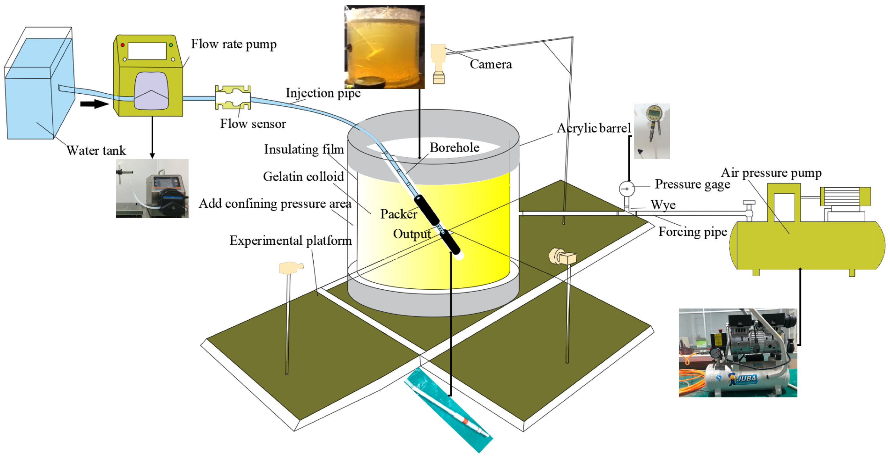
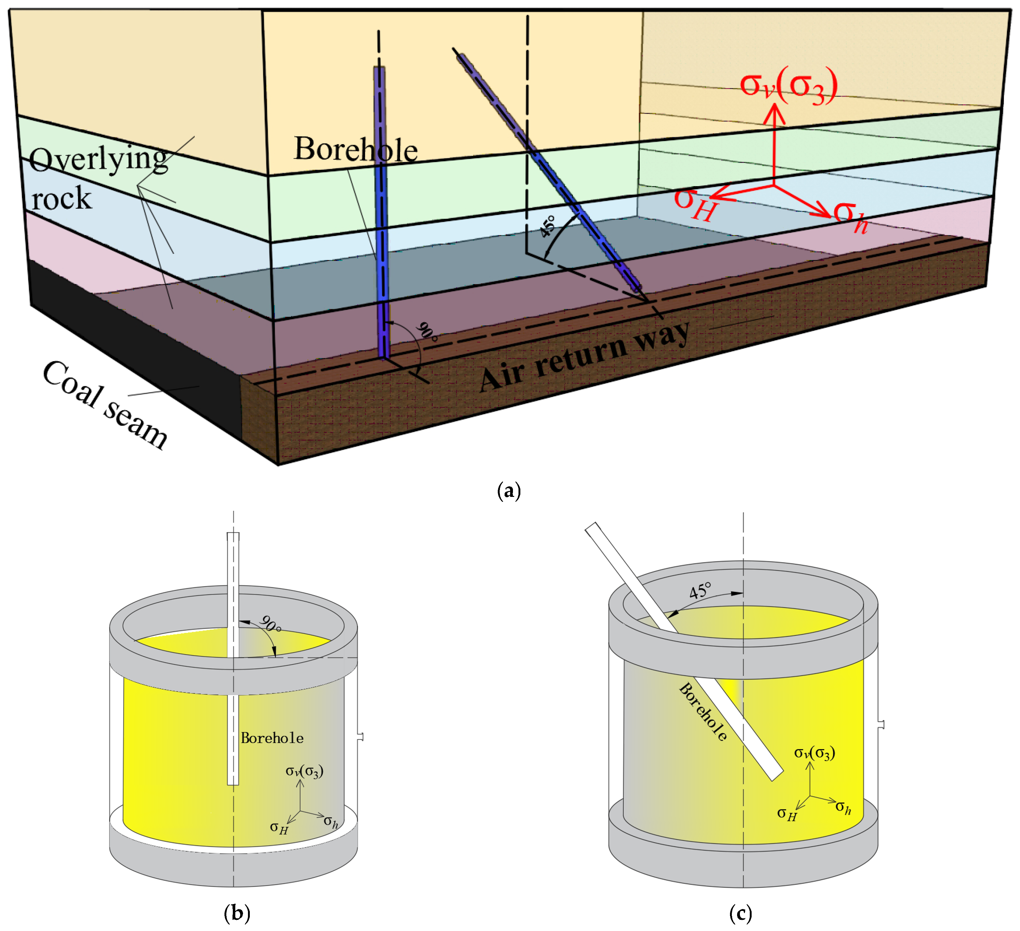
2.1. Experimental Apparatus and Procedure

The self-developed hydraulic fracturing experimental equipment was used in a previous study to investigate hydraulic fracture re-orientation in directional hydraulic fracturing, and further details of the experimental equipment can be found in Zhang et al.’s study [31].
After removing the gelatin samples from the refrigerator, the acrylic bucket containing the gelatin colloid we placed onto the experimental platform, as shown in Figure 1. Then, the fracturing rod, used to simulate the dual-seal-type plug, is placed into the preforming hole. Before the experiment commences, it should be ensured that the injection pipeline is filled with fracturing fluid and that the pressure gauge on the pressurization pipeline is at zero. After all these steps are completed, the air compressor pump is turned on, set to the specified pressure, and then the flow pump is started. Three high-definition cameras are set up at different positions on the experimental platform (Figure 1) to record the crack initiation and propagation trajectories of the hydraulic fracture.
Unlike previous laboratory experiments, the experimental equipment and processes described in Figure 1 can simulate the real condition of hydraulic fracturing in coal mine roof layers.

2.2. Rock Mechanical Properties

Young’s modulus (E) of gelatin is a fundamental mechanical property for analyzing crack propagation behavior because it is related to the appropriate confining pressure in laboratory experiments. Gelatin samples, which are in a well-solidified state and convenient for observing the crack initiation and propagation process, with mass fractions of 6% and 8%, will be selected after comparing gelatin samples with different mass fractions. The procedure for measuring Young’s modulus of the gelatin sample can also follow the indentation tests described by Zhang et al. [31].
After obtaining the indentation tests of the gelatin, Young’s modulus of the 8% mass fraction gelatin sample is calculated to be 38.6 kPa. Young’s modulus of the 6% mass fraction gelatin sample is 22.49 kPa.
The on-site-measured crustal stress data at 30 m from the test hole in the I030902 return roadway are as follows: σv = 7.70 MPa, σH = 12.38 MPa, and σh = 7.17 MPa, with the maximum horizontal crustal stress azimuth at S5.42°E. The ground stress data at 44 m from the test hole are σv = 7.32 MPa, σH = 11.35 MPa, and σh = 6.43 MPa, with the maximum horizontal crustal stress azimuth at S4.3°E. The direction of the maximum horizontal crustal stress is nearly perpendicular to the excavation direction of the I030902 working face, while the direction of the minimum principal stress is parallel to the excavation direction of the working face. The crustal stress azimuth at the roof of the I030902 return roadway and the crustal stress direction in the gelatin experiment are shown in Figure 2. The confining pressure is determined based on the ratio of the elastic modulus to the compressive strength of the rock layer sample using dimensionless analysis.
The uniaxial compressive strength of the first key strata rock of the roof is 45.58 MPa, and the uniaxial compressive strength of the second key strata rock of the roof is 50.02 MPa. The measured Young’s moduli of the 6% and 8% mass fraction gelatin samples are 22,491 Pa and 38,605 Pa, respectively. Therefore, the confining pressure applied to the first key strata stress environment simulation using 8% mass fraction gelatin is 5800 Pa. The confining pressure applied to the second key strata stress environment simulation using 8% mass fraction gelatin is 4960 Pa. The confining pressure applied to the first key strata stress environment simulation using 6% mass fraction gelatin is 3400 Pa, while the confining pressure applied to the second key strata stress environment simulation using 6% mass fraction gelatin is 2800 Pa (Table 1).
Eight sets of gelatin samples are prepared in this experiment, aiming to investigate the following: (1) whether the initiation and propagation state of hydraulic fracturing cracks under different stress environments of key strata (i.e., the confining pressures applied to gelatin samples with different concentrations and the same drilling hole angle) is consistent; (2) the initiation and propagation behavior of hydraulic fracturing cracks under different confining pressures (the different key strata stress environments of the simulation) for the same gelatin sample concentration; and (3) the initiation and propagation behavior of performing holes and hydraulic fracturing cracks with the minimum principal stress angles of 0° and 45° for the same gelatin sample concentration. The experimental scheme is shown in Table 2, where the drilling angle in the table refers to the angle between the preforming hole and the horizontal direction.

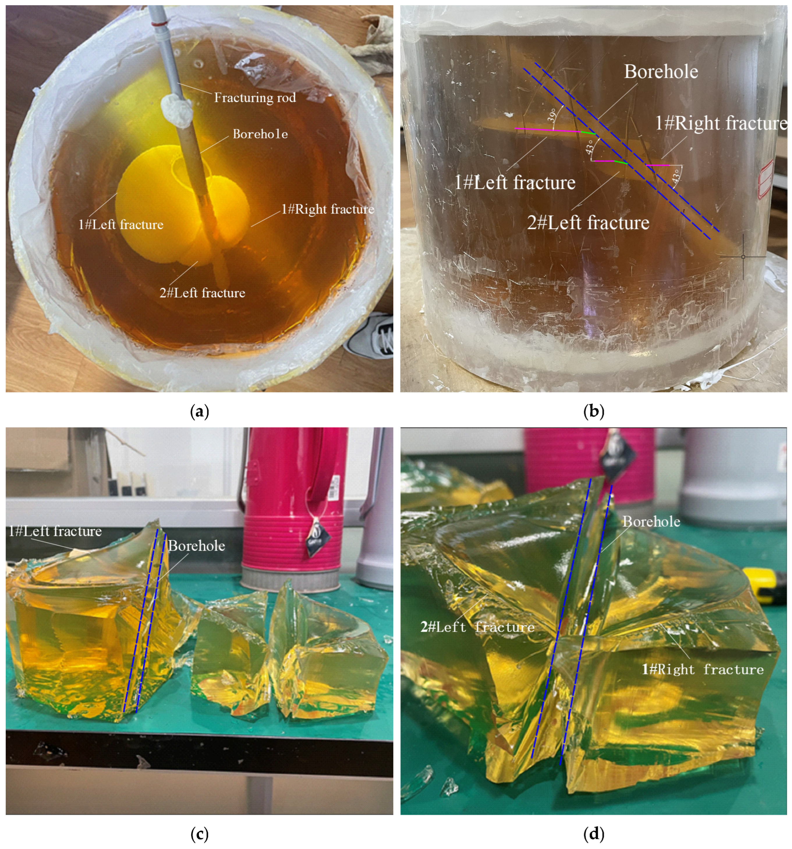
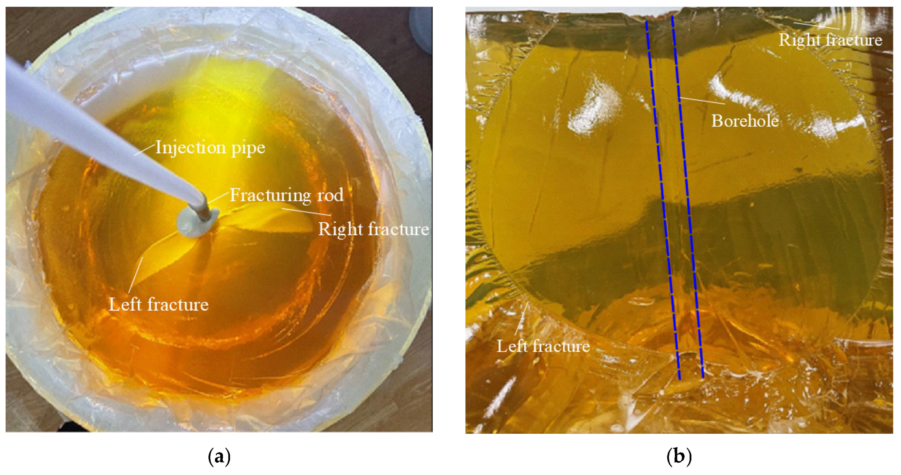
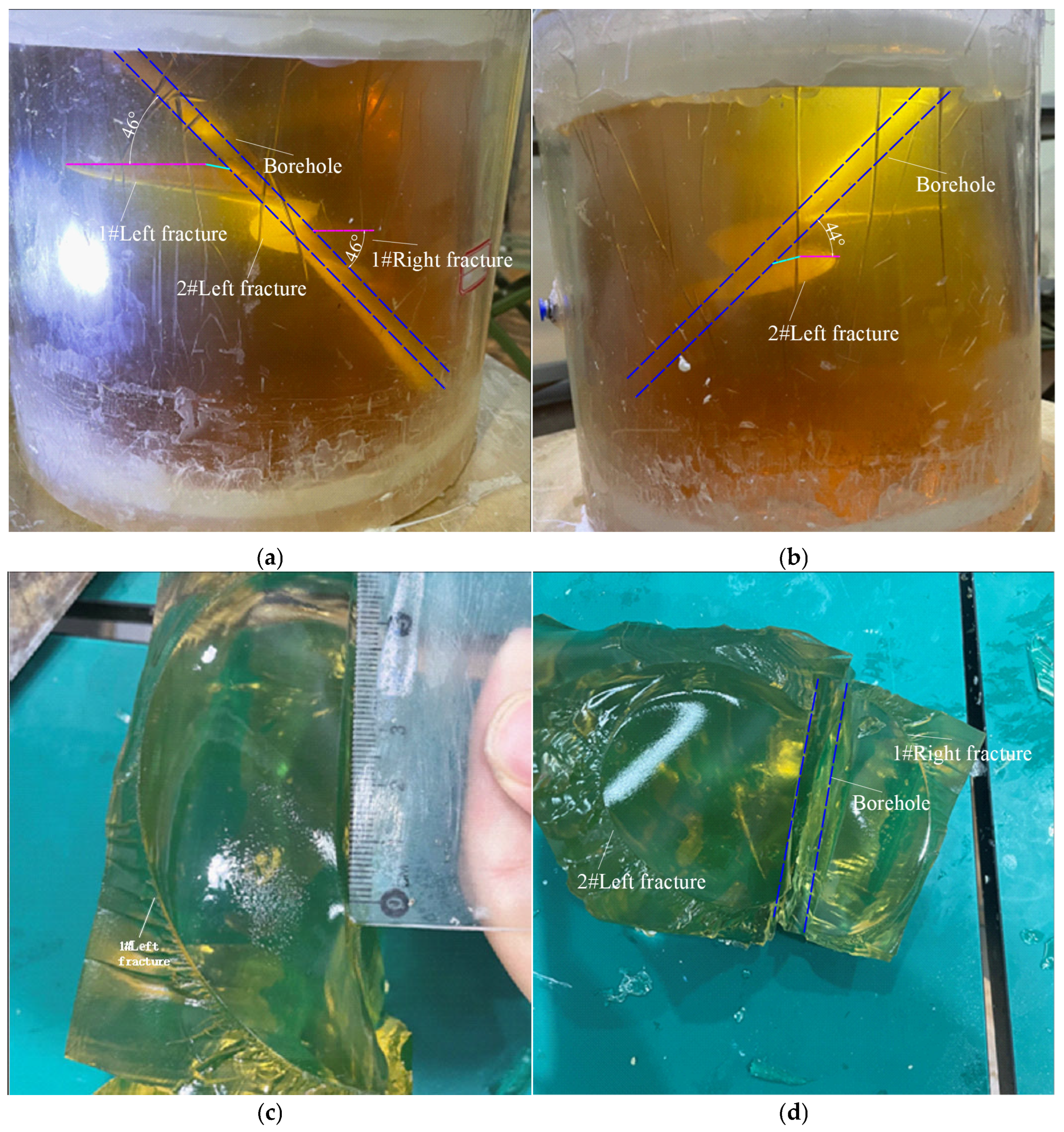
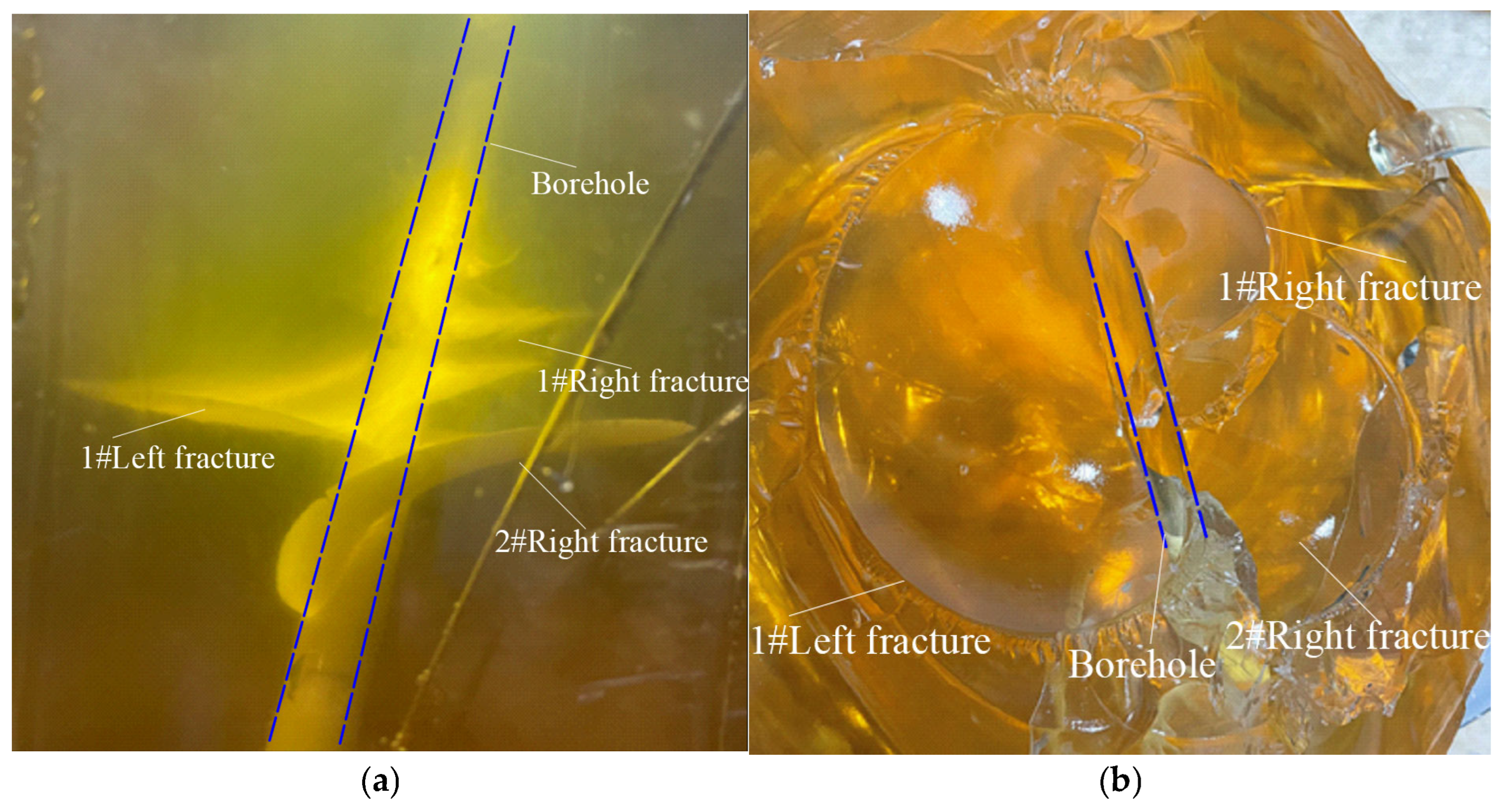
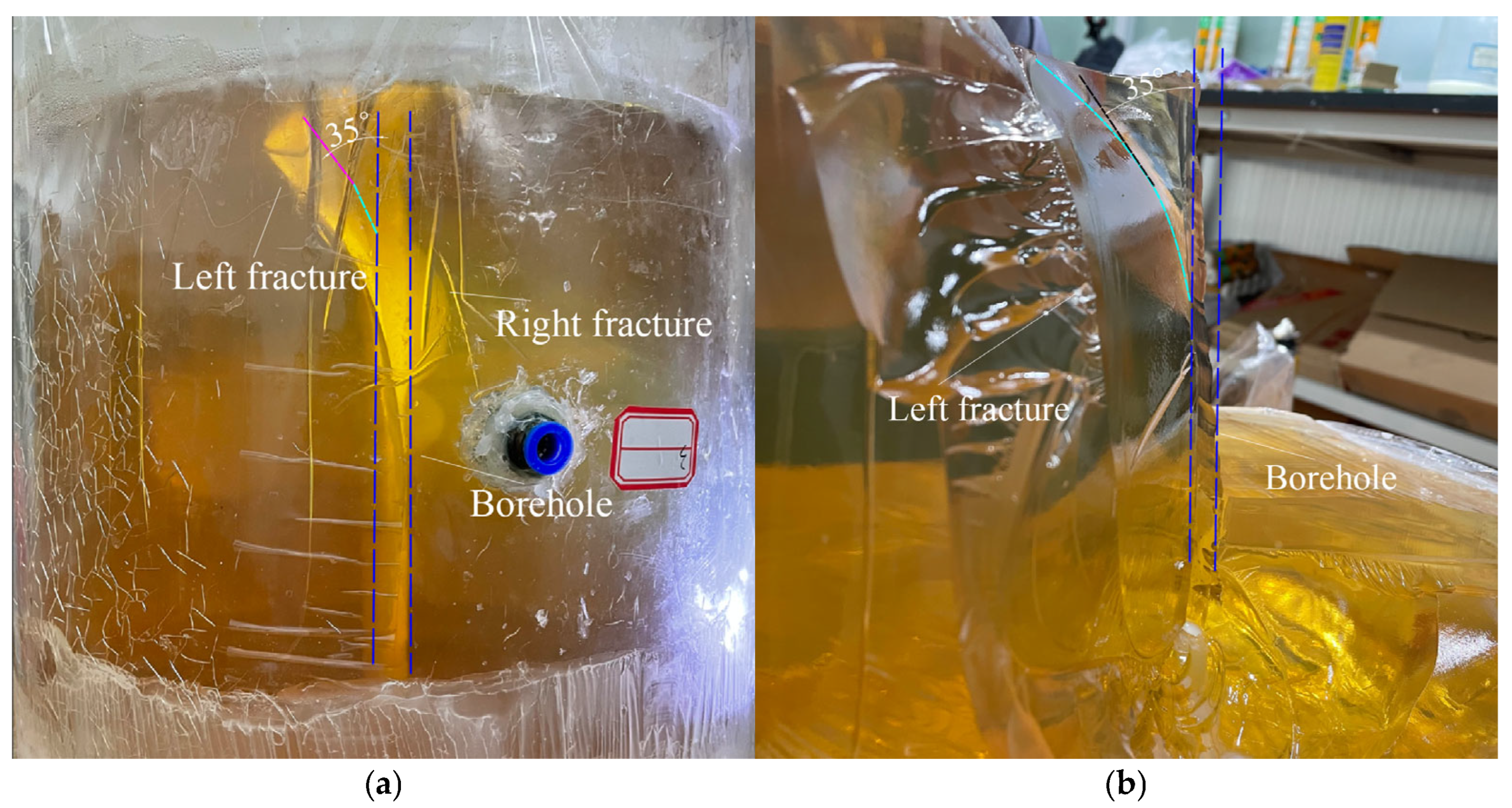
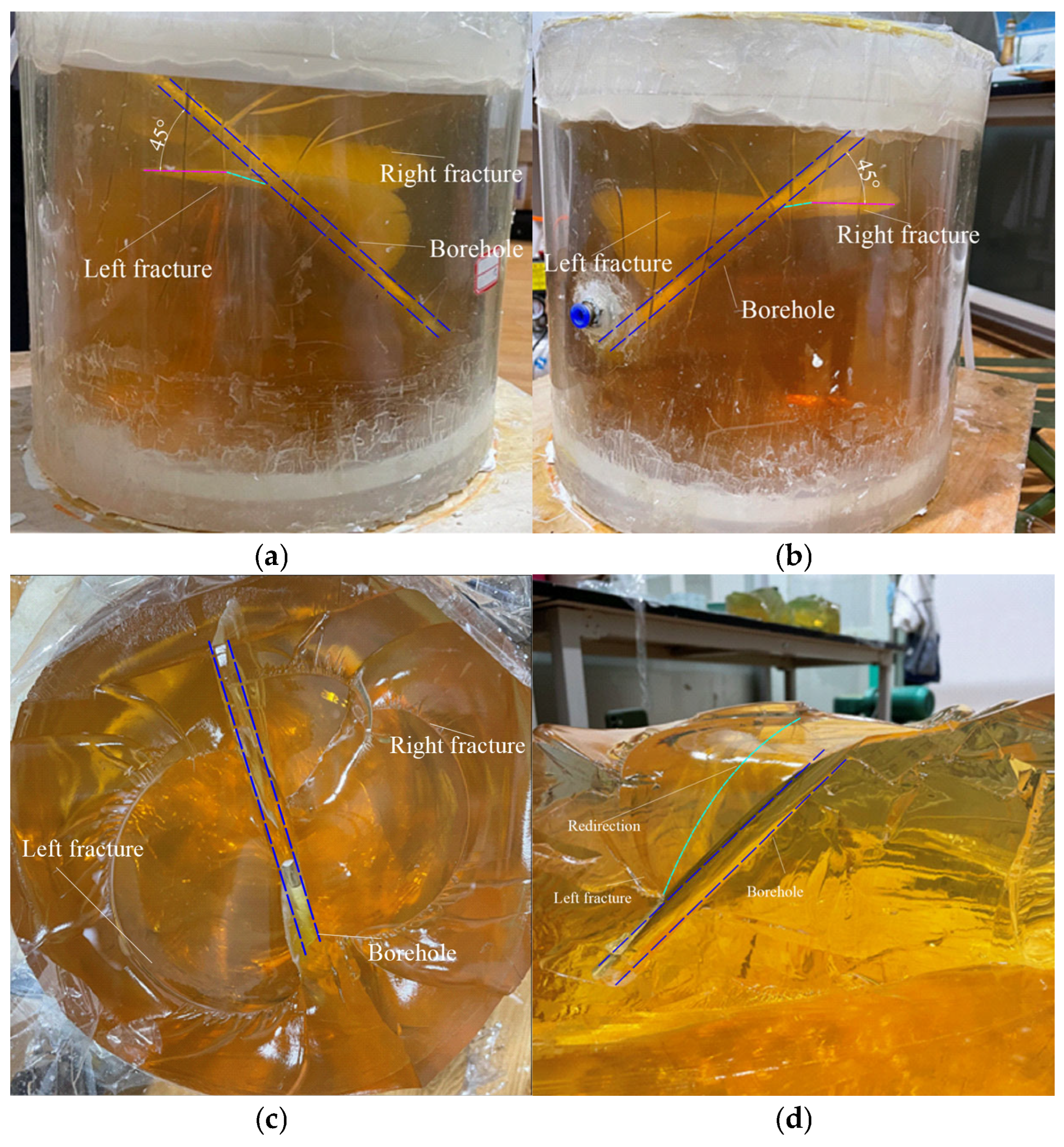
2.3. Analysis of the Results

In this experiment, two parameters will be used to assess the propagation of hydraulic fracturing cracks: crack deflection angle (the angle by which the crack deviates from the preforming hole axis during propagation, which is used to describe the degree of deflection in the crack propagation direction) and deflection distance (the perpendicular distance from the preforming hole axis to the point where the crack changes from axial propagation to radial propagation). These two parameters serve as the evaluation criteria for the status of hydraulic crack propagation.
Figure 3 shows the results of scheme 1-1 (gelatin concentration: 8%, confining pressure: 5800 Pa, preforming hole inclination angle: 90°). The morphology of the hydraulic fracturing cracks is not completely symmetrical (Figure 3a). After a post-dissection observation of the fractured gelatin sample, the main plane of the hydraulic fracture is relatively regular, where only one “fold” can be observed, indicating shear failure (Figure 3b, left wing fracture). The initiation of the hydraulic fracturing cracks occurs along the water discharge area in the middle of the fracturing rod. In this experiment, no single-wing crack was observed; instead, two cracks appeared. Both cracks show deflection and spiral deflection. Although these two cracks have similar shapes, they differ in size: the left wing crack is larger, and its spiral deflection is more pronounced than the right wing crack. The deflection angles of the left wing crack are 78° at the top and 63° at the bottom. The deflection angles of the right wing crack are 73° at the top and 47° at the bottom. The deflection distance of the left wing crack is 13 mm, while the deflection distance of the right wing crack is 14 mm.
Figure 4 shows the results of scheme 1-1 (gelatin concentration: 8%, confining pressure: 5800 Pa, preforming hole inclination angle: 45°). In this set, two cracks appear on the left wing (left wing #1 crack and left wing #2 crack) and one crack on the right wing (right wing #1 crack). The left wing #2 crack and right wing crack form a crack pair. From the images of the sample after dissection in Figure 4c,d, it can be observed that the propagation trajectories of the three cracks are similar. They all initially propagate along the axis of the fracturing hole and then deflect under the effect of confining pressure. Each crack shows a tendency to deflect towards the horizontal, with all cracks showing spiral deflection.
From Figure 4c, it can be seen that left wing #1 crack has extended to the horizontal direction, with obviously spiral propagation. Left wing #1 crack initially propagates along the axis of the fracturing hole and then deflects under confining pressure, extending radially and axially at both the upper and lower ends of the fracturing hole. The deflection angle of left wing #1 crack is 39°, and the deflection distance is 10 mm. Left wing #2 crack has also extended to the horizontal direction and exhibits spiral deflection, indicating that left wing #2 crack also initially propagates along the axis of the fracturing hole and then deflects both radially and axially under confining pressure. The deflection angle is 43°, and the deflection distance is 9 mm. Right wing #1 crack has extended to the horizontal direction and shows a clear twisting, indicating that right wing #1 crack propagates both radially and axially. The deflection angle is 43°.
Figure 5 shows the results of scheme 1-3 (gelatin concentration: 8%, confining pressure: 4960 Pa, preforming hole inclination angle: 90°). The upper of the hydraulic fracturing crack is axial because the hydraulic fracturing crack is about to extend to the gelatin–air interface. Finally, the surface of the hydraulic fracturing crack does not remain perpendicular to the plane where the minimum principal stress is located, which is due to the limit of experimental equipment, not the stress difference. The hydraulic fracturing crack extends symmetrically with a double-wing shape, and there are no “wrinkles” on the crack surface, which means that there is no shear failure (as shown in Figure 5a,b). The initiation of the hydraulic fracturing crack occurs along the water outflow area in the middle of the fracturing rod, and during its propagation, the crack extends along the preforming hole. When the hydraulic fracturing crack reaches the bottom of the hole, shear failure occurs at the bottom of the hole. No spiral twisting is observed, and the hydraulic fracturing crack ultimately forms as an axial crack, while the deflection distance is 0 and the deflection angle is 0.
Figure 6 shows the results of scheme 1-4 (gelatin concentration: 8%, confining pressure: 4960 Pa, preforming hole inclination angle: 45°). Three cracks appeared in this set of samples: two on the left wing (left wing crack #1 and left wing crack #2) and one on the right wing (right wing crack #1), with left wing crack #2 and right wing crack #1 forming a crack group. According to the images of the fractured sample after the dissection shown in Figure 6c,d, the crack propagation trajectories of the three cracks are similar. All cracks first propagate along the axis of the fracturing hole and then deviate under the effect of confining pressure, with a tendency to deflect horizontally.
From Figure 6c, left wing crack #1 has expanded to the horizontal direction, and at the end of its propagation, the crack is near the edge of the cylindrical mold. Due to the edge effect, the crack propagates upward to the gelatin–air interface. The deflection angle of left wing crack #1 is 46°, and the deflection distance is 7 mm. Figure 6d shows that the left wing crack #2 and right wing crack #1 both show a tendency to propagate towards the horizontal direction. left wing crack #2 has expanded radially. The deflection angle of left wing crack #2 is 44°, and the deflection distance is 4 mm. Right wing Crack #1 exhibits obvious twisting, indicating that its propagation includes both radial and axial extensions. The deflection angle of right wing crack #1 is 45°, and the deflection distance is 5 mm.
Figure 7 shows the results of scheme 2-1 (gelatin concentration: 6%, confining pressure: 3400 Pa, preforming hole inclination angle: 90°). The gelatin sample presents a single, complete crack. However, in Figure 7a, the entire crack consists of two wing cracks with a clear boundary between them. Both wing cracks initially appear along the axial of the fracturing hole and then deflect under the effect of confining pressure. Figure 7c,d show that the deflection angle of both wing cracks is 90°, the deflection distance of the left wing crack is 16 mm, and the deflection distance of the right wing crack is 12 mm. The spiral propagation of the two wing cracks is obvious. In this set of experiments, no deflection or extension at the lower end of the wing cracks is observed. Figure 7b indicates that the left wing crack undergoes shear failure during its propagation.
Figure 8 shows the results of scheme 2-2 (gelatin concentration: 6%, confining pressure: 3400 Pa, preforming hole inclination angle: 45°). According to Figure 8a,b, left and right wing cracks with different layers (left wing crack #1 and right wing cracks #1 and #2) can be seen in this experiment set. As shown in Figure 8a, the distances of the left wing crack #1 and right wing crack #2 are approximately 0.6 times the fracturing hole diameter along the axial of the fracturing hole. At the beginning of the fracture of the fracturing hole, all three cracks first propagate along the axis of the fracturing hole and then deflect under the effect of confining pressure. Both the upper and lower ends of left wing crack #1 exhibit twisting. The upper end of left wing crack #1 intersects with right wing crack #1, and left wing rack #1 exhibits a pronounced twisting, while the crack not only extends along the axis of the fracturing hole but also extends radially. Right wing crack #2 extends along the axial from the lower end of the fracturing hole and then turns and deflects radially, also exhibiting clear spiral propagation as it propagates towards the horizontal direction. Right wing Crack #1 consists of two smaller cracks, and the propagation trajectories of these two cracks are similar, also similar to right wing crack #2. The cracks begin to extend from the lower end and both deflect towards the horizontal direction at the upper end. The deflection angles of left wing crack #1 and right wing cracks #1 and #2 are all 45°, and their deflection distances are 2 mm, 2 mm, and 4 mm.
Figure 9 shows the results of scheme 2-3 (gelatin concentration: 6%, confining pressure: 2800 Pa, preforming hole inclination angle: 90°). From Figure 9a, two cracks without any spiral twisting can be seen under the effect of confining pressure: the main left wing crack and a smaller, secondary right wing crack. The main crack exhibits deflection, with only the upper end of the crack deflecting. The deflection angle is 35°, and the deflection distance is 18 mm. The lower end of the secondary right wing crack exhibits slight deflection because the left wing main crack first propagates to the gelatin–air interface, causing a decrease in crack pressure, leading to stopping the propagation of the secondary crack. Wrinkling occurred in the middle of the left wing main crack, but it did not affect the propagation trajectory of the main crack.
Figure 10 shows the results of scheme 2-4 (gelatin concentration: 6%, confining pressure: 2800 Pa, preforming hole inclination angle: 45°). From Figure 10a,b, left and right wing cracks appeared in this set of experiments, and their expansion forms a radial-like crack because two wing cracks combined. Both left and right wing cracks exhibited spiral propagation during their propagation, while the spiral propagation was more pronounced in the left wing crack. The propagation process of the left wing crack begins with the formation of an axial crack segment, followed by deflection at the upper end under the effect of confining pressure, with both radial and lateral expansion towards the horizontal direction. The deflection angle of the left wing crack is 45°, and the deflection distance is 4 mm. The lower end of the left wing crack does not experience deflection. For the right wing crack, the propagation process began with the formation of an axial crack segment, and then the lower end immediately turned towards the horizontal direction. The upper end of the right wing crack, similar to the left wing crack, deflected under confining pressure and expanded radially and laterally towards the horizontal direction. The deflection angle of the right wing crack is 45°, and the deflection distance is 5 mm. Figure 10c,d show that the right wing crack exhibited noticeable wrinkling, indicating shear failure during its propagation.

2.4. Discussion of the Results

The experiment uses gelatin material to conduct the hydraulic fracture simulation tests of the two key strata in a coal mine under a certain flow rate, Young’s modulus, and confining pressure. The experiment chooses deflection angle and deflection distance as the criteria to evaluate the propagation of hydraulic fracturing cracks. The aim is to deeply investigate the following problems: (1) whether the initiation and propagation of hydraulic fracturing cracks under different stress environments in different key strata are consistent (i.e., gelatin samples with different concentrations are subjected to corresponding confining pressures, while the drilling inclination angle remains the same); (2) the initiation and propagation of hydraulic fracturing cracks in gelatin samples with the same concentration under different confining pressure conditions (i.e., simulating stress environments of different key strata); and (3) the initiation and propagation of hydraulic fracturing cracks in gelatin samples with the same concentration under the condition that angles between the preforming holes and the minimum principal stress are 0° and 45°.
The propagation law of cracks under different stress environments obtained from this study provides a theoretical basis for numerical simulation models in applying hydraulic fracture morphology. It also offers a reference for whether the drilling holes in the hydraulic fracturing test of the roof support testing at coal mines should be arranged with an inclination.
The results of sets 1-1, 1-4, and 2-1 and 2-4 exhibit a high degree consistency in crack propagation, especially in the crack propagation path, deflection trends, and spiral propagation. This indicates that although the material properties and stress conditions differ, the basic laws of crack propagation are similar in the gelatin samples of two concentrations. The feasibility of simulating different key strata with varying confining pressures has been verified, and the randomness of conducting fracturing experiments with a single concentration is eliminated.
The crack propagation behavior shows significant differences under the conditions of the same gelatin concentration but different confining pressures (representing different key strata). Under lower confining pressure conditions, the cracks propagate more symmetrically with smaller deflection angles and distances, and less shear failure occurs. In contrast, under higher confining pressure conditions, the fractures exhibit more deflection, spiral propagation, and shear failure.
The arrangement angle of pre-drilling holes affects crack propagation significantly under the same confining pressure and gelatin concentration. When the preforming holes are arranged at an inclined angle, the deflection distance and deflection angle are smaller, and the cracks exhibit more deflection and spiral propagation. The trajectory is more complex, and the asymmetric stress field exacerbates branching and spiral propagation. Additionally, crack propagation shifts from radial to axial more quickly and forms radial cracks, which promotes the shift in propagation mode.

3. Field Test

According to the initiation and propagation law of hydraulic fracturing cracks in different key layers in the gelatin experiment of the hydraulic fracturing laboratory, the on-site industrial tests of regional strata hydraulic fracturing were conducted in the return roadway of the I030902 working face at Limin Coal Mine.

3.1. Geological Background

Figure 11 shows the underground reference diagram of the I030902 working face. A 5 m narrow coal pillar is left between the transport roadway of the I030901 working face and the return roadway of the I030902 working face. The immediate roof of the 9−1 coal seam consists of grayish-black sandy mudstone, and above the immediate roof are mudstone, sandy mudstone, and coarse-grained sandstone. The main component of the main roof above the coal seam is coarse-grained sandstone. The immediate floor consists of grayish-black mudstone and sandy mudstone.
The return roadway of the I030902 working face has experienced local mesh bulging, the bending of steel bands, floor fragmentation, floor heaving, and coal pillar deformation due to the mining activities of this working face. Through the monitoring and analysis of the surrounding rock displacement and stress variation processes in the return roadway of the I030902 working face, it can be concluded that the 5 m narrow coal pillar left between the I030902 and I030901 working face’s goaf is unable to fully withstand the dynamic pressure and lateral support pressure during the mining process. During the mining excavation, severe surface deformation of the roadway occurred, which increased the maintenance costs of the return roadway. Therefore, hydraulic fracturing has been selected to treat the roof of the return roadway near the narrow coal pillar in the regional stratum.

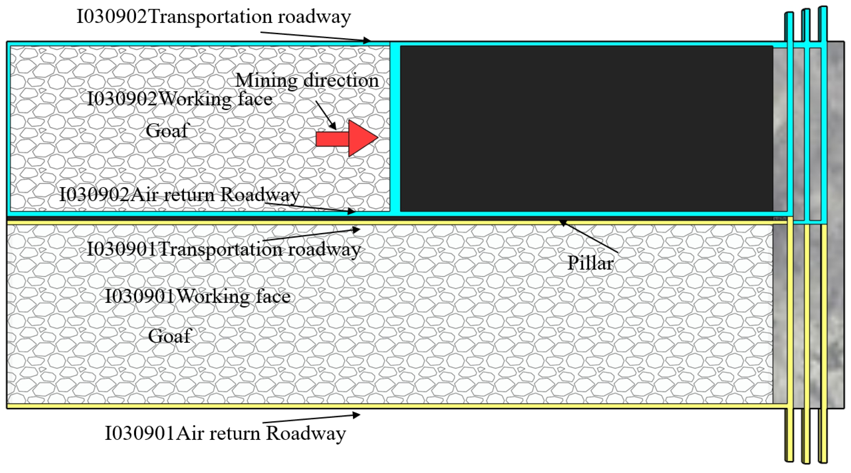
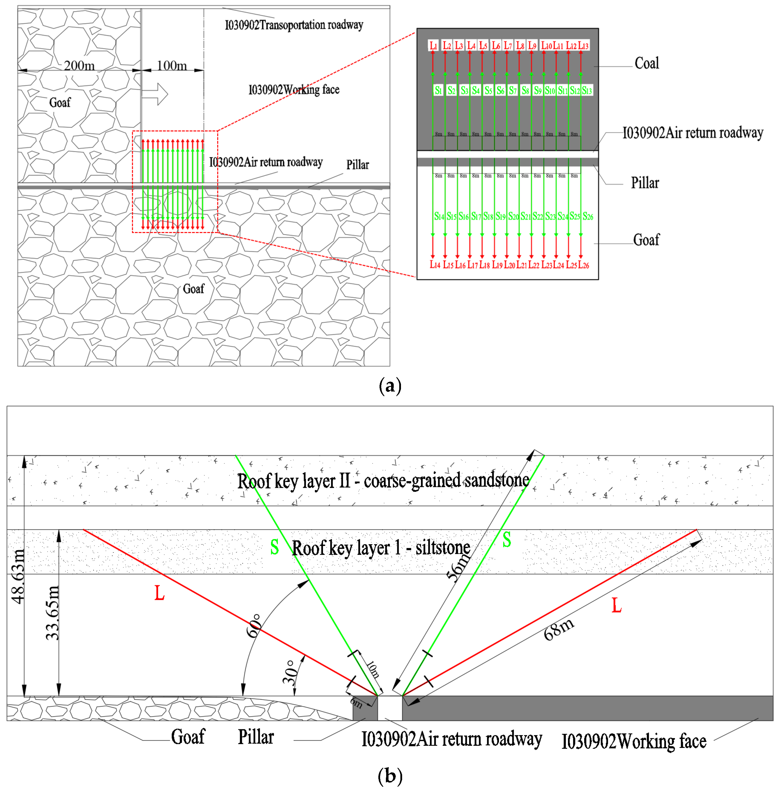
3.2. Engineering Background

Based on the on-site crustal stress measurements, two thick and hard key strata of impact-induced strata were identified in the return roadway of the I030902 working face. The fracture heights of the regional strata are 29.15 m and 43.54 m. Therefore, two types of inclined drilling holes are arranged on-site: L-shape drilling hole to fracture the rock mass in the key strata zone 1 of the roof, and S-shape drilling hole to fracture the rock mass in the key strata zone 2 of the roof.
Based on the initiation and propagation characteristics of hydraulic fracturing cracks in different key strata analyzed in the gelatin experiments, the hydraulic fracturing cracks ultimately perpendicular to the minimum principal stress plane. The maximum principal stress direction measured by the ground stress measurements is almost perpendicular to the excavation direction of the I030902 working face (W0.73°S), with orientations of S5.42° and S4.3°E. The direction of the minimum principal stress is parallel to the excavation direction of the I030902 working face. Therefore, the drilling hole arrangement should be perpendicular to the strike of the working face, which means that the angle between the drilling hole direction and the return roadway direction should be 90°. Since 200 m of the I030902 working face has already been mined, the experiment is conducted for the 200 m–300 m section, with drilling conducted at the same location for both the L-shape and S-shape drilling holes. The hydraulic fracturing parameters for the regional strata are shown in Table 3. The drilling hole arrangement diagram for the regional strata hydraulic fracturing is shown in Figure 12.

3.3. Analysis of the Results

The fracturing status of the drilling holes in the return roadway of the I030902 working face and the layout of measurement points are shown in Figure 13b. The length of the fracturing section is 100 m, and the length of the non-fracturing section is 100 m. A total of 20 measurement points are set: 1#, 2#, 3#, 4#, 5#, 6#, 7#, 8#, 9#, 10#, 11#, 12#, 13#, 14#, 15#, 16#, 17#, 18#, 19#, and 20#. The distance between each point is 10 m. Each measurement point includes equipment for monitoring roof and floor convergence, the two sidewall convergences, and the anchor bolt strain gauge. A cross-point layout method is used to monitor the convergence of the roof and floor, and the sidewall convergence of the tunnel, while the anchor bolt strain gauge is used to monitor side stress changes in the coal pillar. Monitoring data are collected from each measurement point every 10 m of tunnel excavation.
The following conclusions can be drawn from the analysis of the average resistance of the supports in the working face (Figure 14):
(1)
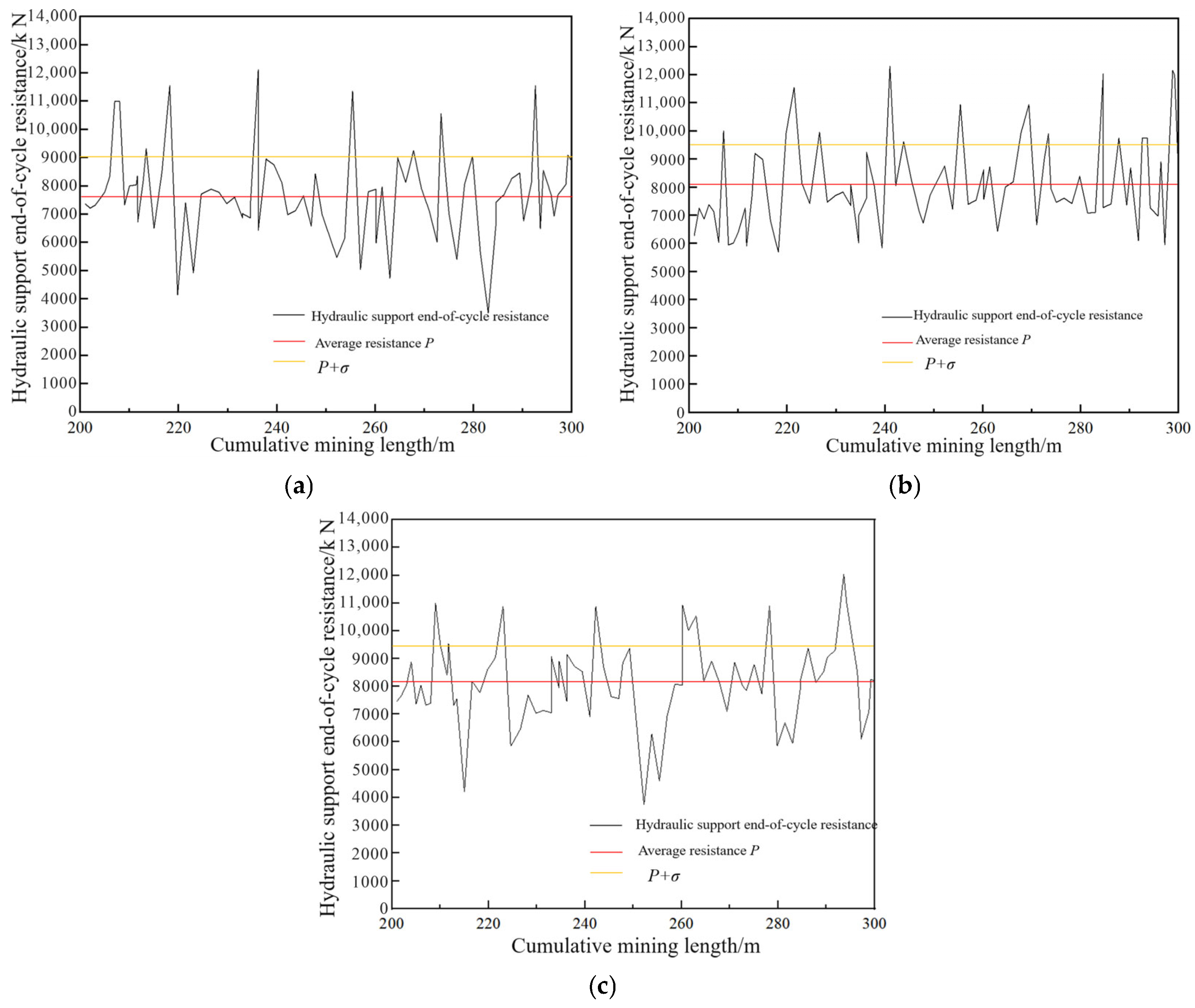
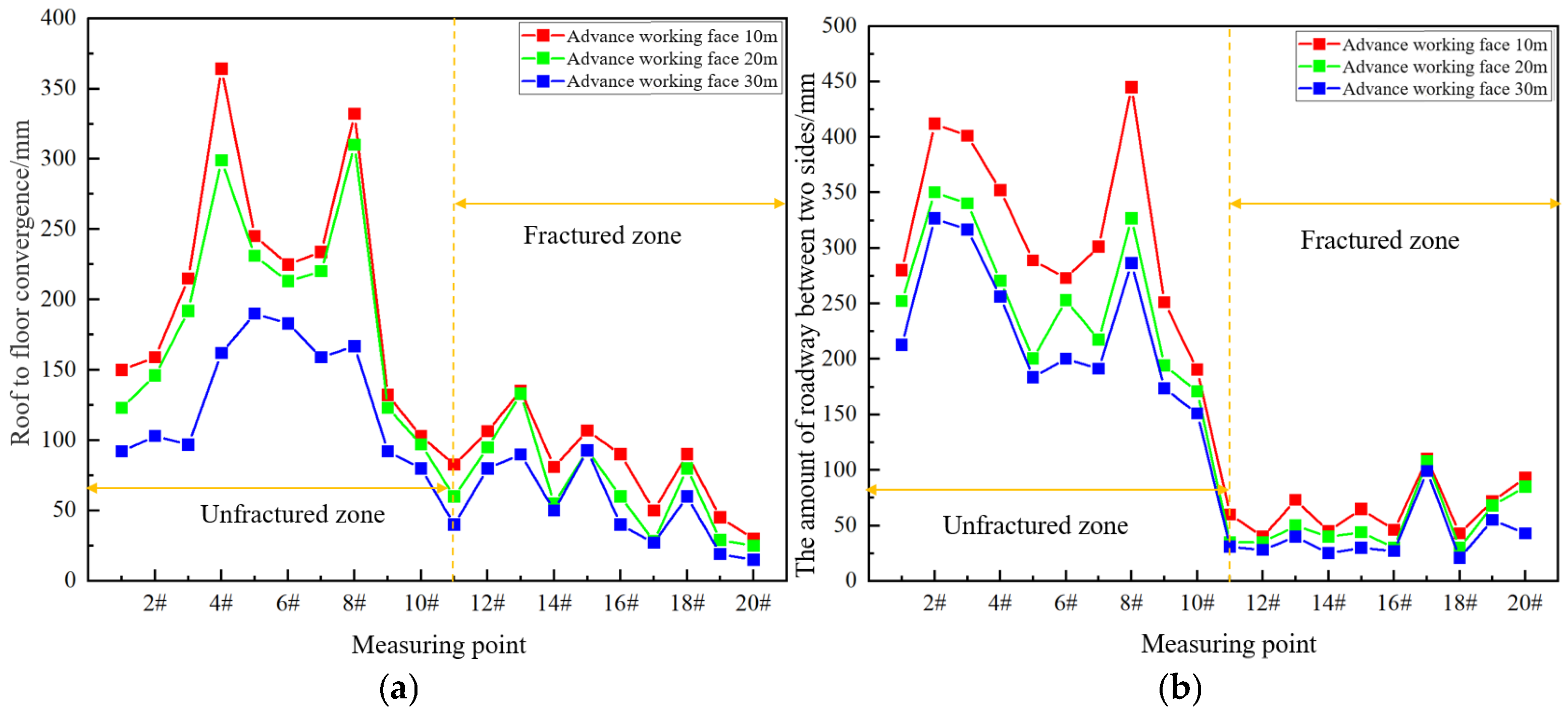
Cutting the roof to relieve pressure artificially disrupts the roof rock strata, causing changes in its structure. After roof cutting, the continuity of the roof rock strata, which are originally intact and under high stress, breaks, and its hanging roof effect is weakened. The average resistance of the supports in the fracturing area is significantly lower than that in the middle and upper sections of the working face, with a particularly noticeable decrease when compared to the middle section excavation direction.
(2)
The average resistance of the supports in the working face begins to decrease before the fracturing zone fracture, indicating that the influence area of fracturing extends more than 34 m along the inclination projection direction of the fracturing drilling hole in the working face.
(3)
Based on four sets of recorded data, when the working face excavated 100 m, the average resistance of the supporting structure in the upper part of the working face is 7253.1 kN, in the middle part it is 8690.2 kN, and in the fractured area it is 5486.0 kN. The support resistance in the pressure relief area is reduced by 24.3% and 36.8% compared to the upper and middle sections of the working face, which indicates a good pressure relief effect.
The monitoring and analysis of the resistance of the supporting structure after each excavation cycles in the 100–200 m section of the working face show that the periodic step distance of the pressure at the working face is 20 m. Figure 15 shows the mining pressure curve based on the resistance of the supporting structure after each of the excavation cycles at hydraulic supports 33# in the upper part of the working face, 110# in the middle part, and 154# in the fractured impact area during the 200–300 m excavation (fracturing test section). The periodic pressure increase is judged by data points greater than the sum of the average support cycle end resistance (P) and its standard deviation (σ). From the figure, it can be observed that the maximum pressure for support 33# is 12,355.66 kN, with an average pressure of 7724.6 kN. The periodic pressure step distance ranges from 11 to 19 m, and the average step distance is 17 m. The maximum pressure for support 110# is 12,153.69 kN, with an average pressure of 8064.0 kN. The periodic pressure step distance ranges from 14 to 20 m, and the average step distance is 15.4 m. The maximum pressure for support 154# is 12,040.18 kN, with an average pressure of 8198.3 kN. The periodic pressure step distance ranges from 14 to 19 m, and the average step distance is 16.8 m.
Based on the mine pressure curve plotted during the excavation of the working face by 100 to 200 m, the average pressure of the supporting structure is 9725.3 kN. The average pressure of the 33#, 110#, and 154# hydraulic supports is 7995.6 kN during the excavation of the working face from 200 to 300 m, a decrease of 17.8% compared with the pressure from 100 to 200 m. At the same time, the average step distance has decreased by 18% compared to the 100–200 m excavation.
In summary, the pressure of the supporting structure in the working face direction and the periodic average step distance of the pressure both decrease after roof cutting. Roof cutting promotes staged fracturing of the roof, preventing a large-scale simultaneous collapse, thereby reducing the intensity of each pressure. Roof cutting creates pre-fracturing surfaces artificially, cutting the roof into discrete short cantilever units. The vertical cracks formed facilitate the redistribution of horizontal stress, with part of the pressure converting into lateral stress parallel to the working face, reducing the driving effect of the stress gradient in the working face direction on periodic roof fracturing.
The data from monitoring points 1#–10# correspond to the unfractured section, while the data from monitoring points 11#–20# correspond to the fractured section. The data from 10 m to 30 m ahead of the working face from each monitoring point were analyzed to obtain the data curve (Figure 16).
The maximum roof to floor convergence increase in the non-fractured section is 137 mm, while in the fractured section, the convergence is 50 mm. The maximum amount of roadway between two sides in the non-fractured section increases by 158.7 mm, while in the fractured section, the amount increases by 47 mm. Compared to the non-fractured section, the average roof to floor convergence rate (the daily roof and floor convergence of the working face, when the daily excavation distance of the working face is 2.4 m) decreases from 10.10 mm/d to 3.65 mm/d, and the amount of roadway between the two sides’ convergence rate (the daily convergence of the amount of roadway between two sides at the working face) decreases from 10.80 mm/d to 2.98 mm/d.

4. Conclusions

Severe mining-induced stress was observed in the I030902 working face return roadway of Liming Coal Mine, and hydraulic fracturing was used to relieve pressure on the narrow coal pillar roof. The following conclusions were drawn from the hydraulic fracturing experiments using gelatin material and on-site industrial hydraulic fracturing tests in the return roadway at the I03-0902 working face:
Under the same gelatin concentration but different confining pressure conditions (in different key strata), the propagation law of hydraulic fracturing cracks exhibits significant differences. Under lower confining pressure conditions, the propagation of cracks is more symmetrical, with smaller deflection angles and deflection distances, and less shear failure. In contrast, under higher confining pressure conditions, the propagation of cracks shows more deflection, spiral propagation, and shear failure.
Under the same confining pressure and gelatin concentration conditions, the arrangement angles of the pre-drilling holes have a significant impact on fracture propagation. When the holes are arranged at an inclined angle, the deflection distances and deflection angles are smaller than those with a vertical arrangement, where the propagation of cracks exhibits more deflection and spiral propagation, resulting in a more complex trajectory. The asymmetric stress field intensifies branching and spiral propagation, and the fractures can transition from radial to axial propagation more quickly, forming radial cracks and promoting changes in the propagation mode.
Based on the analysis of the on-site test results, it was found that after hydraulic fracturing, the roof pressure decreased by 17.8%, the average pressure step distance reduced by 18.0%, the average roof to floor convergence rate in the tunnel decreased by 63.86%, and the average roof to floor convergence rate dropped by 72.4%. The results verify the feasibility of hydraulic fracturing used in addressing the strong dynamic pressure caused by mining stress in the return roadway and controlling the deformation of the tunnel by forming a weak structural structure in the hard roof.
In the future, we will focus on the in-depth study of stress shadow effects in transparent gelatin materials.

Author Contributions

Conceptualization, T.S. and Z.L.; data curation, Z.L. and B.L.; formal analysis, T.S. and B.L.; funding acquisition, Q.H. and D.M.; investigation, Z.L., D.M. and X.G.; methodology, T.S. and Q.H.; project administration, Q.H.; supervision, Q.H.; validation, T.S., Z.L., B.L. and X.G.; visualization, D.M., B.L. and X.G.; writing—original draft, T.S. and Z.L.; writing—review and editing, D.M., B.L. and X.G. All authors have read and agreed to the published version of the manuscript.

Funding

The work is financially supported by the National Key R&D Program of China (2022YFC2905600) and the National Natural Science Foundation of China (U23B2091).

Institutional Review Board Statement

Not applicable.

Informed Consent Statement

Not applicable.

Data Availability Statement

The original contributions presented in this study are included in the article. Further inquiries can be directed to the corresponding authors.

Conflicts of Interest

Author T.S. was employed by the Shaanxi Bureau of State Mine Safety Supervision Bureau. Author Z.L. was employed by the Inner Mongolia Limin Coal Char Co., CHN Energy Wuhai Energy Company. The remaining authors declare that this research was conducted in the absence of any commercial or financial relationships that could be construed as potential conflicts of interest.

Nomenclature

Eelastic modulus, Pa
σHthe maximum horizontal principal stress, Pa
σhthe minimum horizontal principal stress, Pa
σvthe vertical stress, Pa
σ3the minimum principal stress, Pa1

References

  1. Fu, Q.; Yang, J.; Gao, Y.; Li, C.; Song, H.; Liu, Y.; Wu, X. Combined blasting for protection of gob-side roadway with thick and hard roof. J. Rock Mech. Geotech. Eng. 2024, 16, 3165–3180. [Google Scholar] [CrossRef]
  2. Chao, Z.; Baiquan, L.; Fei, L.; Shuai, Z.; Feifei, L. The Research of Quaternity of Drilling-Blasting-Fracturing- Extracting Technology and Application of Outburst. Procedia Eng. 2011, 26, 449–456. [Google Scholar] [CrossRef]
  3. Li, C.; Yang, R.; Zuo, J.; Xie, P. Theory and field tests of innovative cut blasting method for rock roadway excavation. Tunn. Undergr. Space Technol. 2025, 155, 106180. [Google Scholar] [CrossRef]
  4. Zou, J.; Wu, K.; Zhang, X.; Zhu, J.; Zhou, Z.; Zheng, F.; Xie, H.; Jiao, Y.-Y. Effective evaluation of deep-hole blasting for controlling strong tremors induced by deep coal mining—A case study. Int. J. Rock Mech. Min. Sci. 2022, 159, 105211. [Google Scholar] [CrossRef]
  5. Zhang, Q.; He, M.; Wang, J.; Guo, S.; Zhu, C.; Tao, Z.; Wang, C. Investigation of a non-explosive directional roof cutting technology for self-formed roadway. Int. J. Min. Sci. Technol. 2022, 32, 997–1008. [Google Scholar] [CrossRef]
  6. Yang, L.; Yang, A.; Chen, S.; Fang, S.; Huang, C.; Xie, H. Model experimental study on the effects of in situ stresses on pre-splitting blasting damage and strain development. Int. J. Rock Mech. Min. Sci. 2021, 138, 104587. [Google Scholar] [CrossRef]
  7. Liu, J.; Wang, H.; Yuan, Z.; Fan, X. Experimental Study of Pre-splitting Blasting Enhancing Pre-drainage Rate of Low Permeability Heading Face. Procedia Eng. 2011, 26, 818–823. [Google Scholar]
  8. Jiang, K.; Deng, S.; Li, Y.; Li, H. Calculating the number of radial cracks around a wellbore fractured by liquid CO2 phase transition blasting technology. J. Rock Mech. Geotech. Eng. 2024, 16, 4515–4531. [Google Scholar] [CrossRef]
  9. Zhu, B.; Jiang, N.; Yao, Y.; Luo, X. SPH numerical simulation of SC-CO2 directional fracturing and emulsion explosives for rock breaking. Gas Sci. Eng. 2024, 124, 205277. [Google Scholar] [CrossRef]
  10. Cao, Y.; Zhang, J.; Zhang, X.; Liu, S.; Elsworth, D. Micro-fractures in coal induced by high pressure CO2 gas fracturing. Fuel 2022, 311, 122148. [Google Scholar] [CrossRef]
  11. Habib, K.-M.; Vennes, I.; Mitri, H.S. Methodology for the estimation of expansive cement borehole pressure. Int. J. Min. Sci. Technol. 2023, 33, 73–81. [Google Scholar] [CrossRef]
  12. De Silva, V.R.S.; Konietzky, H.; Ranjith, P.G.; Manatunga, U.I. Strain energy dependent numerical simulation of rock fracture initiation and propagation using soundless cracking demolition agents (SCDA): Effects of SCDA-filled rock joints. Int. J. Rock Mech. Min. Sci. 2024, 177, 105740. [Google Scholar] [CrossRef]
  13. Xu, J.; Zhai, C.; Qin, L.; Yu, G. Evaluation research of the fracturing capacity of non-explosive expansion material applied to coal-seam roof Rock. Int. J. Rock Mech. Min. Sci. 2017, 94, 103–111. [Google Scholar] [CrossRef]
  14. Qin, J.; Xian, C.; Zhang, J.; Liang, T.; Wang, W.; Li, S.; Zhang, J.; Zhang, Y.; Zhou, F. Characteristics of hydraulic fracture network in the tight conglomerate reservoir based on a hydraulic fracturing test site. Pet. Explor. Dev. 2025, 52, 245–257. [Google Scholar] [CrossRef]
  15. Yin, W.; Feng, Z.; Zhao, Y. Effect of fracture backfill on the hydraulic fracturing behaviour of deep granite under high-temperature and high-pressure conditions: Implications for hot dry rock geothermal mining. Renew. Energy 2025, 243, 122507. [Google Scholar] [CrossRef]
  16. Zhou, H.; Huang, X.; Jiang, L.; Shen, Q.; Sun, H.; Yi, M.; Wang, X.; Yao, X.; Wu, Y.; Zhang, C.; et al. Improved degradation of petroleum contaminants in hydraulic fracturing flowback and produced water using laccase immobilized on functionalized biochar. Environ. Technol. Innov. 2023, 32, 103280. [Google Scholar] [CrossRef]
  17. Aliu, A.O.; Guo, J.; Wang, S.; Zhao, X. Hydraulic fracture fluid for gas reservoirs in petroleum engineering applications using sodium carboxy methyl cellulose as gelling agent. J. Nat. Gas Sci. Eng. 2016, 32, 491–500. [Google Scholar] [CrossRef]
  18. Wang, X.; Wu, W.; Wang, X.; Song, Z.; Sheng, J.J. Numerical investigating oil-water flow in shale oil reservoirs accounting for fracture swarms and injected hydraulic fluids. Geoenergy Sci. Eng. 2025, 247, 213717. [Google Scholar] [CrossRef]
  19. Guanhua, N.; Hongchao, X.; Zhao, L.; Lingxun, Z.; Yunyun, N. Improving the permeability of coal seam with pulsating hydraulic fracturing technique: A case study in Changping coal mine, China. Process Saf. Environ. Prot. 2018, 117, 565–572. [Google Scholar] [CrossRef]
  20. He, Q.; Suorineni, F.; Ma, T.; Oh, J. Effect of discontinuity stress shadows on hydraulic fracture re-orientation. Int. J. Rock Mech. Min. Sci. 2017, 91, 179–194. [Google Scholar] [CrossRef]
  21. He, Q.; Suorineni, F.; Ma, T.; Oh, J. Parametric study and dimensional analysis on prescribed hydraulic fractures in cave mining. Tunn. Undergr. Space Technol. 2018, 78, 47–63. [Google Scholar] [CrossRef]
  22. He, Q.; Zhu, L.; Li, Y.; Li, D.; Zhang, B. Simulating Hydraulic Fracture Re-orientation in Heterogeneous Rocks with an Improved Discrete Element Method. Rock Mech. Rock Eng. 2021, 54, 2859–2879. [Google Scholar] [CrossRef]
  23. Gao, S.; Congo, T.; Jing, Z.; Aziz, S.; Balucan, R.; Zhu, Z.; Pell, S.D.; Steel, K.M. Oxidative effects of gaseous oxygen and ozone on Australian subbituminous and bituminous coals and the implications for coal seam permeability enhancement. Gas Sci. Eng. 2023, 118, 205092. [Google Scholar] [CrossRef]
  24. Zhuang, J.; Mu, Z.; Cai, W.; He, H.; Hosking, L.J.; Xi, G.; Jiao, B. Multistage hydraulic fracturing of a horizontal well for hard roof related coal burst control: Insights from numerical modelling to field application. Int. J. Min. Sci. Technol. 2024, 34, 1095–1114. [Google Scholar] [CrossRef]
  25. Huang, B.; Liu, C.; Fu, J.; Guan, H. Hydraulic fracturing after water pressure control blasting for increased fracturing. Int. J. Rock Mech. And. Min. Sci. 2011, 48, 976–983. [Google Scholar] [CrossRef]
  26. He, Q.; Suorineni, F.T.; Oh, J. Strategies for Creating Prescribed Hydraulic Fractures in Cave Mining. Rock Mech. Rock Eng. 2017, 50, 967–993. [Google Scholar] [CrossRef]
  27. Michael, A. Transparent gelatin as a reservoir analogue: Dimensional scaling for hydraulic fracturing laboratory experiments. Int. J. Rock Mech. Min. Sci. 2024, 177, 105732. [Google Scholar] [CrossRef]
  28. Yew, C.H.; Weng, X. Mechanics of Hydraulic Fracturing; Gulf Professional Publishing: Houston, TX, USA, 1972. [Google Scholar]
  29. Gou, B.; Zhan, L.; Guo, J.; Zhang, R.; Zhou, C.; Wu, L.; Ye, J.; Zeng, J. Effect of different types of stimulation fluids on fracture propagation behavior in naturally fractured carbonate rock through CT scan. J. Pet. Sci. Eng. 2021, 201, 108529. [Google Scholar] [CrossRef]
  30. Stockhausen, H.L.J.; Montgomery, C. Outside gravel-pack optimization, based on hydraulic fractures done in gelatin. In Proceedings of the SPE Annual Technical Conference and Exhibition, Dallas, TX, USA, 1–4 October 2000. SPE-63234-MS. [Google Scholar]
  31. Zhang, H.; Liu, B.; He, Q. Visualized Hydraulic Fracture Re-Orientation in Directional Hydraulic Fracturing by Laboratory Experiments in Gelatin Samples. Appl. Sci. 2024, 14, 2047. [Google Scholar] [CrossRef]
Figure 1. Schematic diagram of the hydraulic fracturing experimental equipment (revised from the literature [30]).
Applsci 15 04759 g001
Figure 2. A diagram showing the relationship between the drilling direction of the gelatin sample and the I030902 return airway and the angle with the minimum principal stress: (a) the drilling direction in the I030902 return airway forms an angle of 45° with the minimum principal stress, and the drilling direction is parallel to the minimum principal stress; (b) the pre-drilling hole inclination angle in the gelatin sample is 90°; (c) the pre-drilling hole inclination angle in the gelatin sample is 45°.
Applsci 15 04759 g002
Figure 3. The results of scheme 1-1: (a) top view of hydraulic fracturing cracks; (b) profile view of hydraulic fracturing cracks; (c) front view of hydraulic fracturing cracks; (d) right view of hydraulic fracturing cracks.
Applsci 15 04759 g003
Figure 4. The results of scheme 1-2: (a) top view of hydraulic fracturing cracks; (b) front view of hydraulic fracturing cracks; (c) profile view of the left wing #1 crack; (d) profile view of the left wing #2 crack and right wing #1 crack.
Applsci 15 04759 g004
Figure 5. The results of scheme 1-3: (a) top view of hydraulic fracturing cracks; (b) profile view of hydraulic fracturing cracks.
Applsci 15 04759 g005
Figure 6. The results of scheme 1-4: (a) front view 1 of hydraulic fracturing cracks; (b) front view 2 of hydraulic fracturing cracks; (c) profile view of the left wing #1 crack; (d) profile view of the left wing #2 crack and right wing #1 crack.
Applsci 15 04759 g006
Figure 7. The results of scheme 2-1: (a) front view 1 of hydraulic fracturing cracks; (b) front view 2 of hydraulic fracturing cracks; (c) left view of hydraulic fracturing cracks; (d) right view of hydraulic fracturing cracks.
Applsci 15 04759 g007
Figure 8. The results of scheme 2-2: (a) front view of hydraulic fracturing cracks; (b) profile view of hydraulic fracturing cracks.
Applsci 15 04759 g008
Figure 9. The results of scheme 2-3: (a) front view of hydraulic fracturing cracks; (b) profile view of hydraulic fracturing cracks.
Applsci 15 04759 g009
Figure 10. The results of scheme 2-4: (a) front view 1 of hydraulic fracturing cracks; (b) front view 2 of hydraulic fracturing cracks; (c) profile view 1 of hydraulic fracturing cracks; (d) profile view 2 of hydraulic fracturing cracks.
Applsci 15 04759 g010
Figure 11. The underground reference diagram of the I030902 working face.
Applsci 15 04759 g011
Figure 12. The borehole arrangement diagram: (a) borehole layout plan; (b) borehole layout cross-sectional view.
Applsci 15 04759 g012
Figure 13. Station arrangement: (a) working face hydraulic support distribution diagram; (b) layout of measuring station in air return roadway.
Applsci 15 04759 g013
Figure 14. The average resistance of the supporting structure at the working face: (a) the working face excavated 25 m; (b) the working face excavated 50 m; (c) the working face excavated 75 m; (d) the working face excavated 100 m.
Applsci 15 04759 g014
Figure 15. The resistance of the supporting structure after each of the excavation cycles: (a) the supporting structure after each of the excavation cycles at hydraulic support 33#; (b) the supporting structure after each of the excavation cycles at hydraulic support 110#; (c) the supporting structure after each of the excavation cycles at hydraulic support 154#.
Applsci 15 04759 g015
Figure 16. The monitor data curve of the surface displacement of the surrounding rock and the stress condition of the bolts: (a) roof to floor convergence; (b) the amount of roadway between two sides.
Applsci 15 04759 g016
Table 1. The confining press applied to gelatin samples corresponding to each key strata for different gelatin concentrations.
Gelatin Sample Concentration (%)Elastic Modulus of Gelatin (Pa)Uniaxial Compressive Strength of Rock (MPa)Apply Confining Pressure (Pa)
838,60545.584960
838,60550.025800
622,49145.583400
622,49150.022800
Table 2. Experiment plan for the gelatin tests.
CaseConfining Pressure (Pa)Concentration (%)Dip Angle of Borehole (°)Simulated Key Strata Serial Number
1-15800890first key strata
1-25800845first key strata
1-34960890second key strata
1-44960845second key strata
2-13400690first key strata
2-23400645first key strata
2-32800690second key strata
2-42800645second key strata
Table 3. The parameter of the hydraulic fracturing.
TypeNumberBorehole Depth (m)Azimuth Angle (°)Dip Angle (°)Pitch of Boreholes (m)
L-borehole2668180°308
S-borehole2657180°608
Disclaimer/Publisher’s Note: The statements, opinions and data contained in all publications are solely those of the individual author(s) and contributor(s) and not of MDPI and/or the editor(s). MDPI and/or the editor(s) disclaim responsibility for any injury to people or property resulting from any ideas, methods, instructions or products referred to in the content.

