

A Review of Evaporite Beds Potential for Storage Caverns: Uncovering New Opportunities


Abstract
1. Introduction
2. Evaporites and Bedded Evaporite Deposits
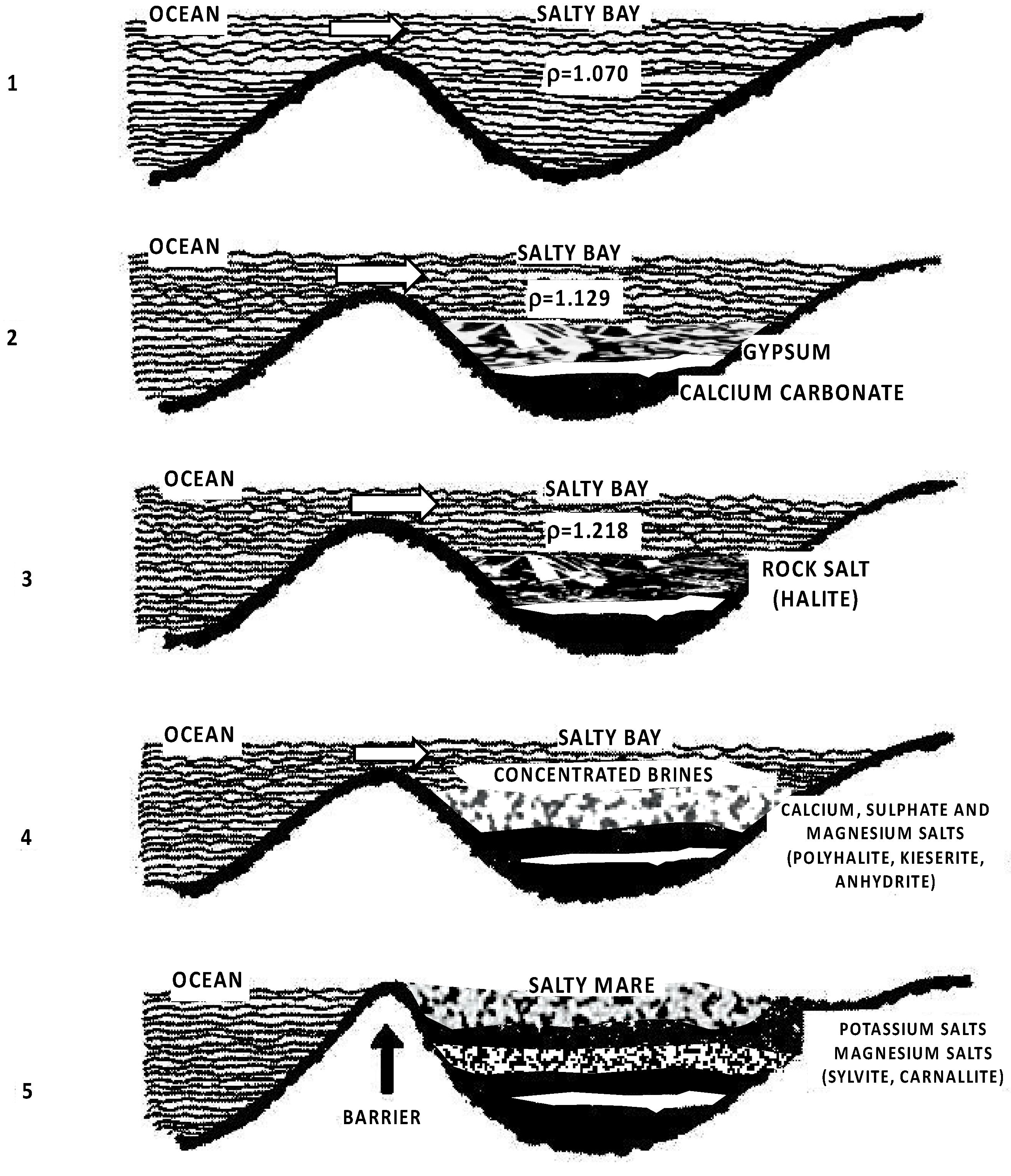
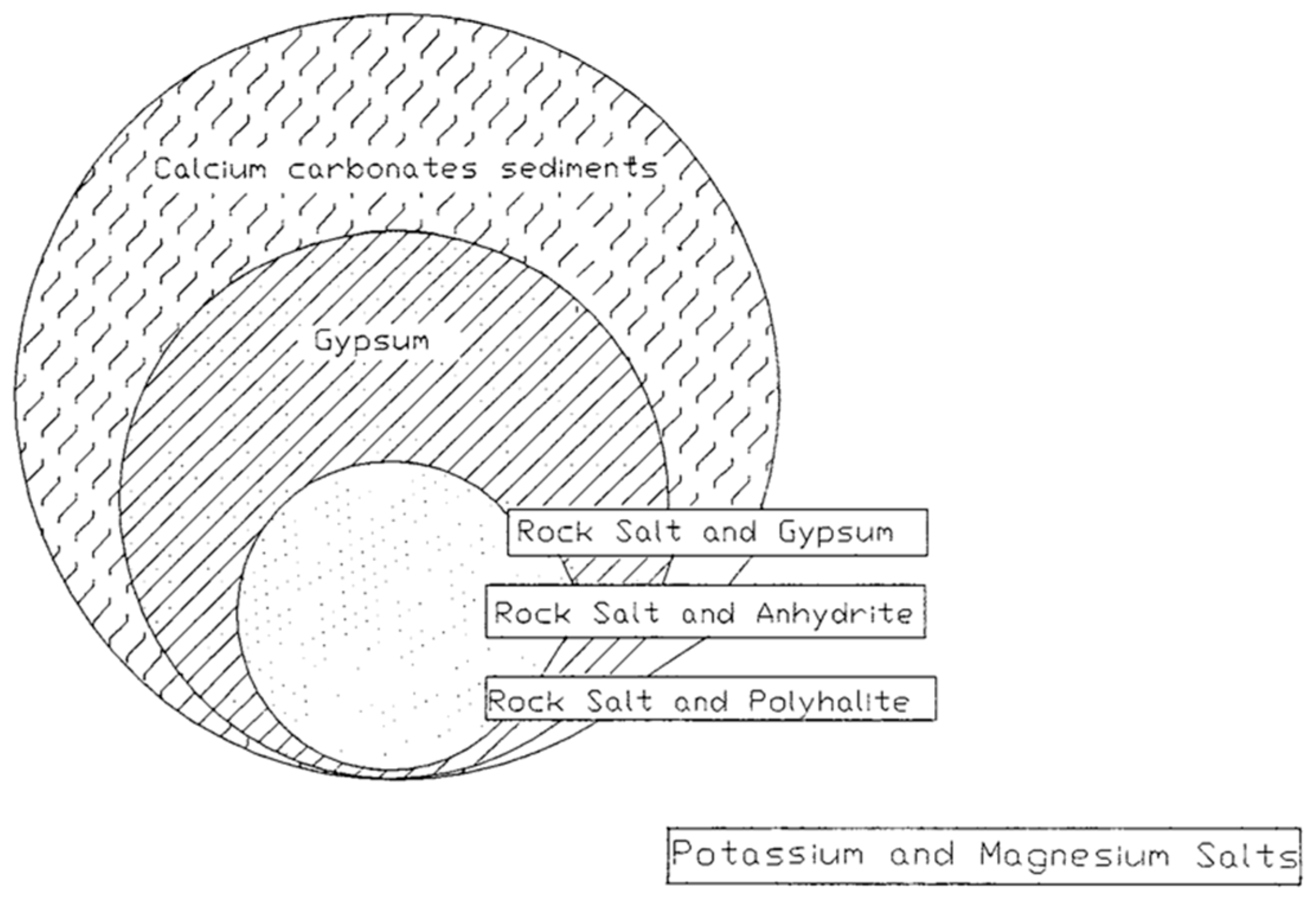
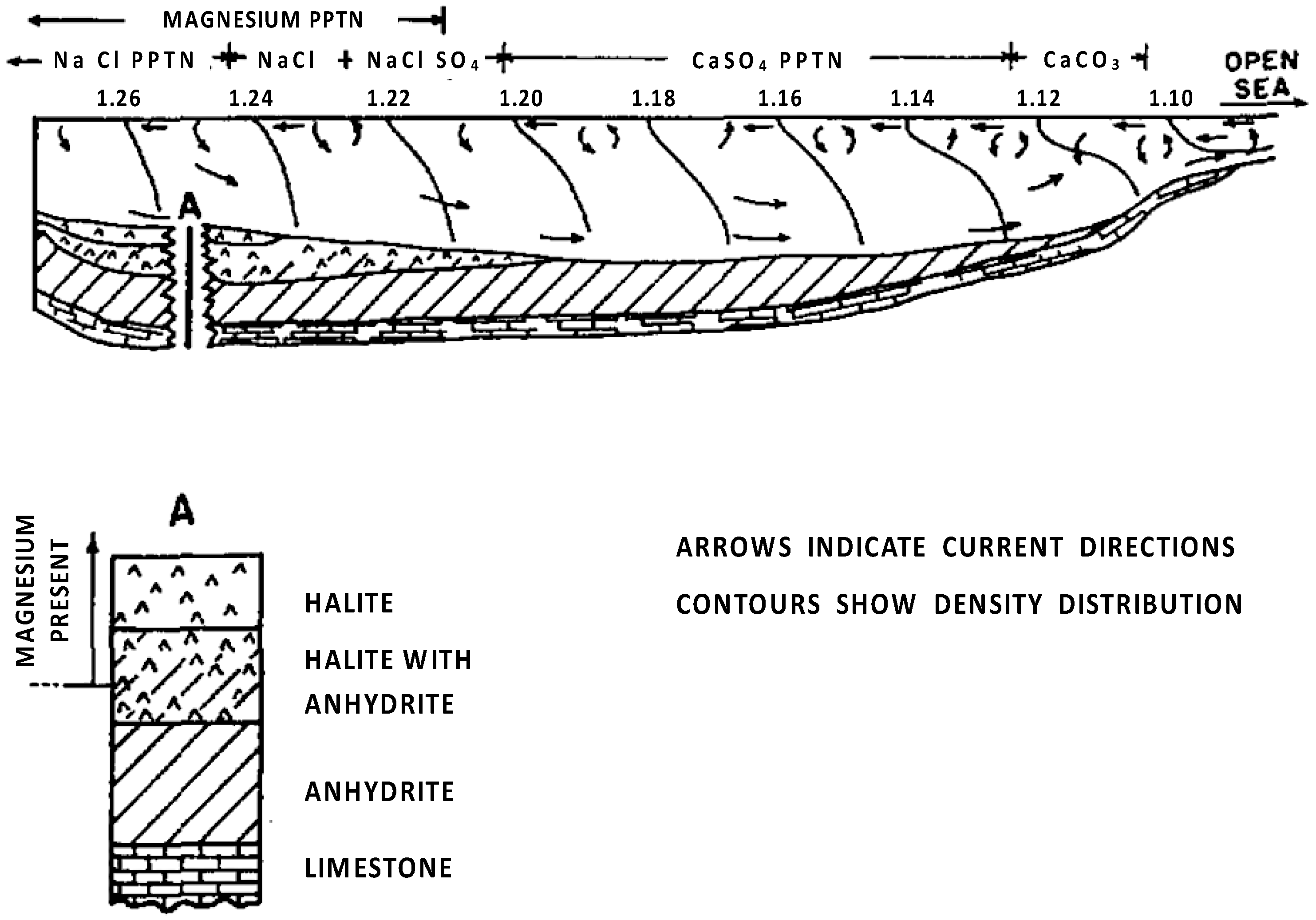
2.1. Origin of Evaporites
- Isolation of an arm of the sea by a barrier with periodic inflow of fresh seawater;
- Increase in mineral concentration within the arm;
- The continued flow of seawater into the arm further raises mineral concentration and brine density;
- Deposition of various evaporites leads to a reduction in basin depth;
- Separation of the basin from the sea due to geological factors, like uplift.
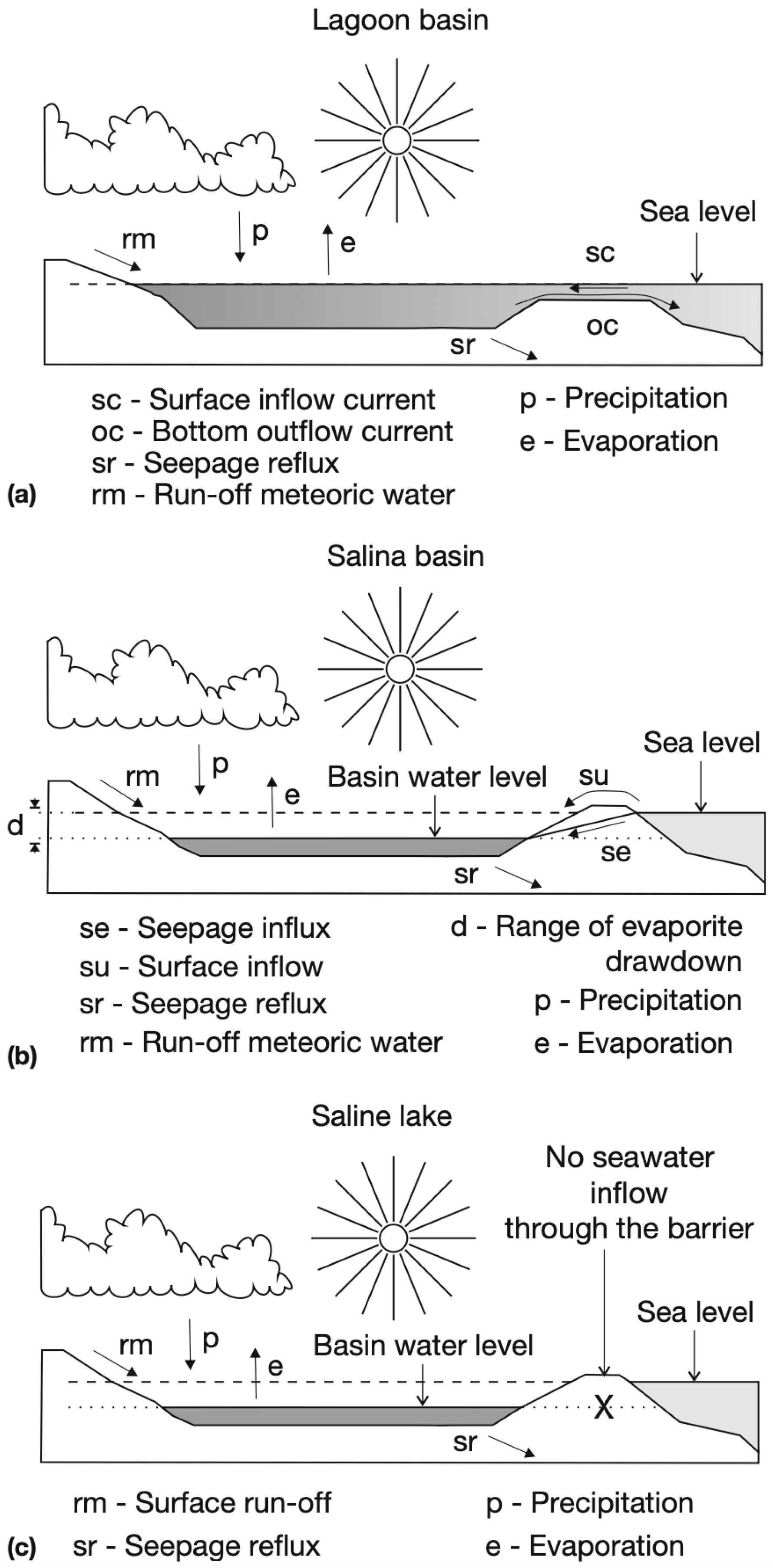
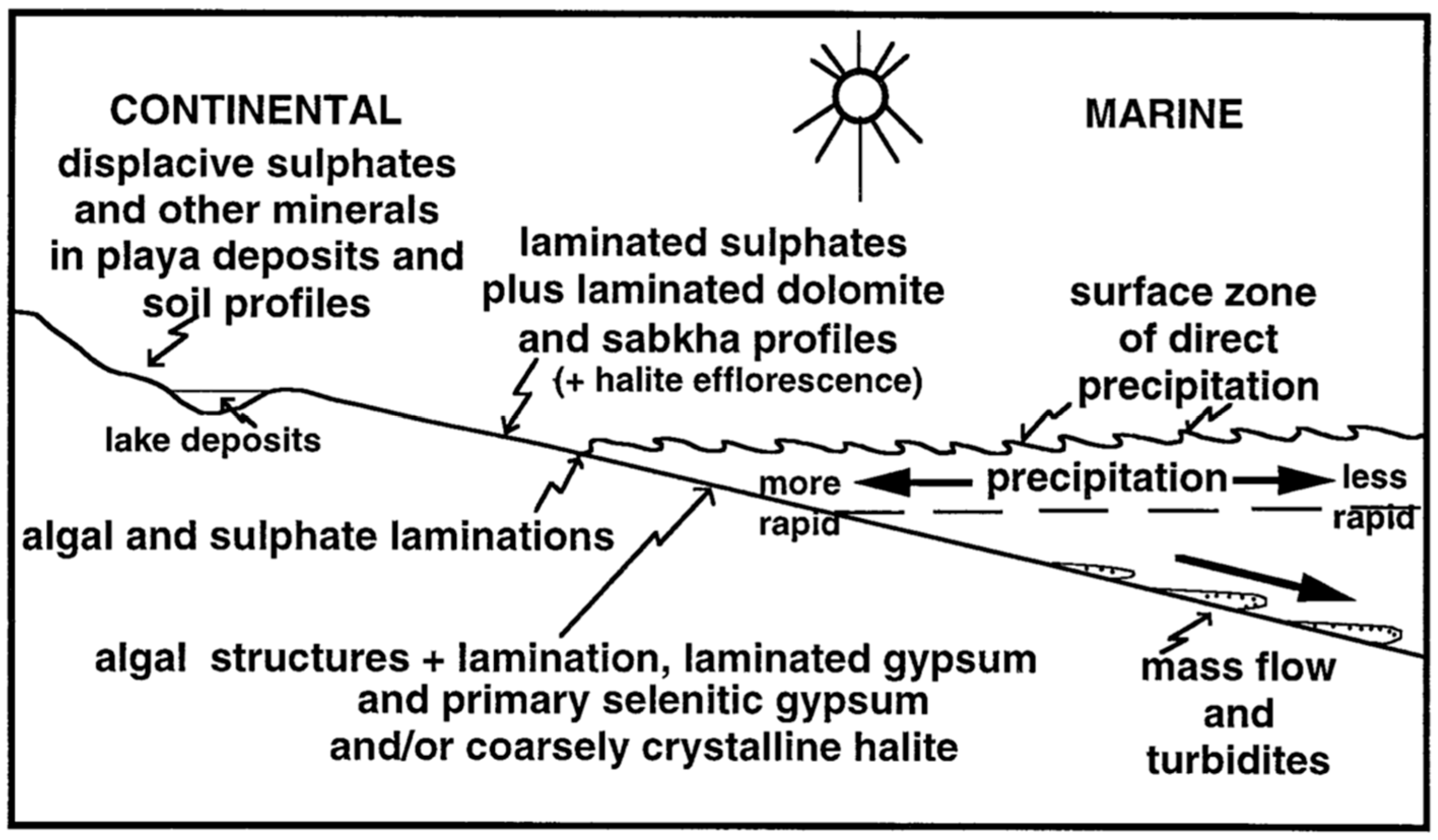
2.2. Depositional Environment of Evaporites
2.3. Evaporite Minerals
2.4. Bedded Evaporite Deposits and Caverns in the U.S. and Canada
2.4.1. Bedded Evaporites
2.4.2. Caverns in the Bedded Evaporites
3. Properties and Geomechanics of Bedded Evaporites
3.1. Physical Properties
3.2. Mechanical Properties
3.3. Main Geomechanical Considerations in Bedded Evaporite Caverns
3.3.1. Cavern Design
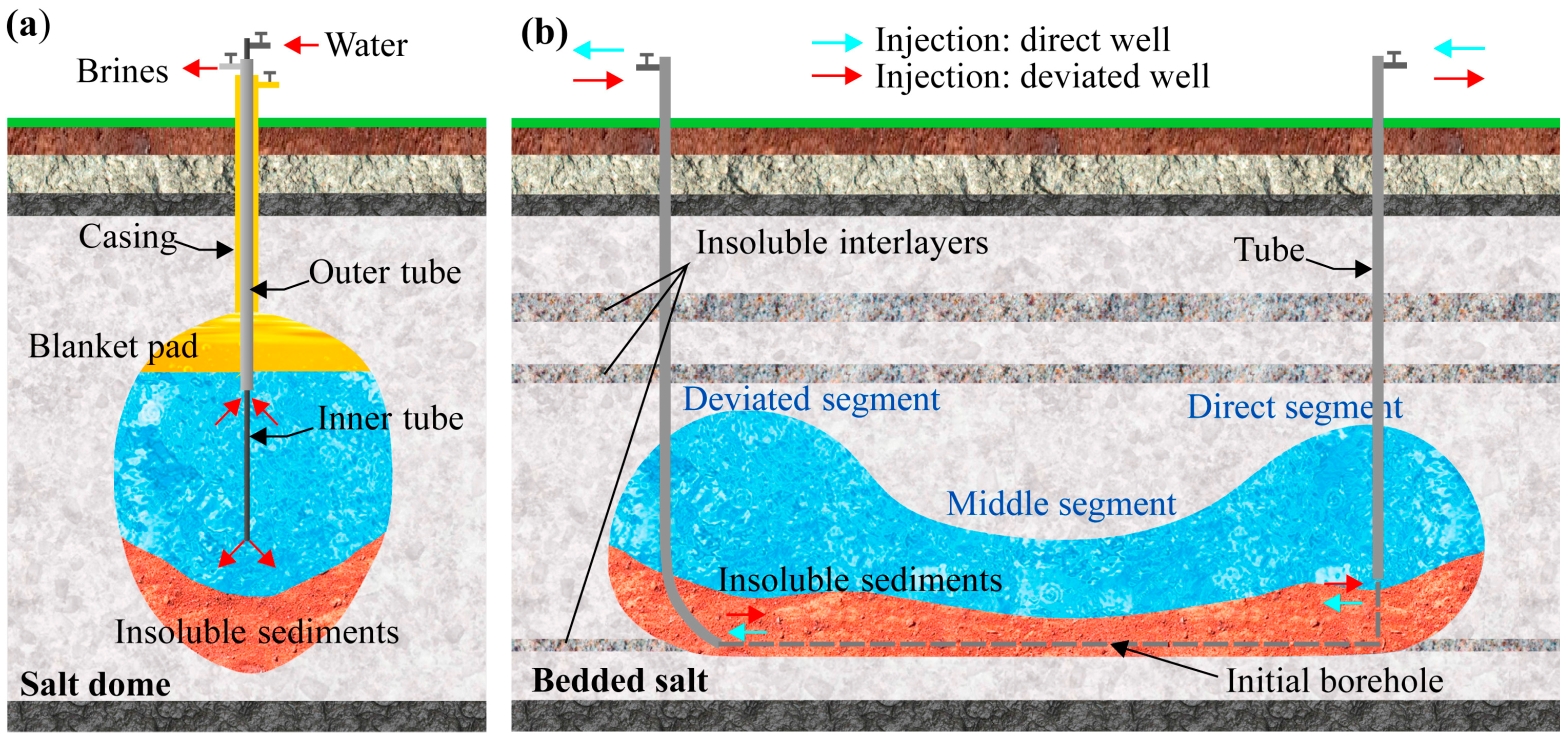
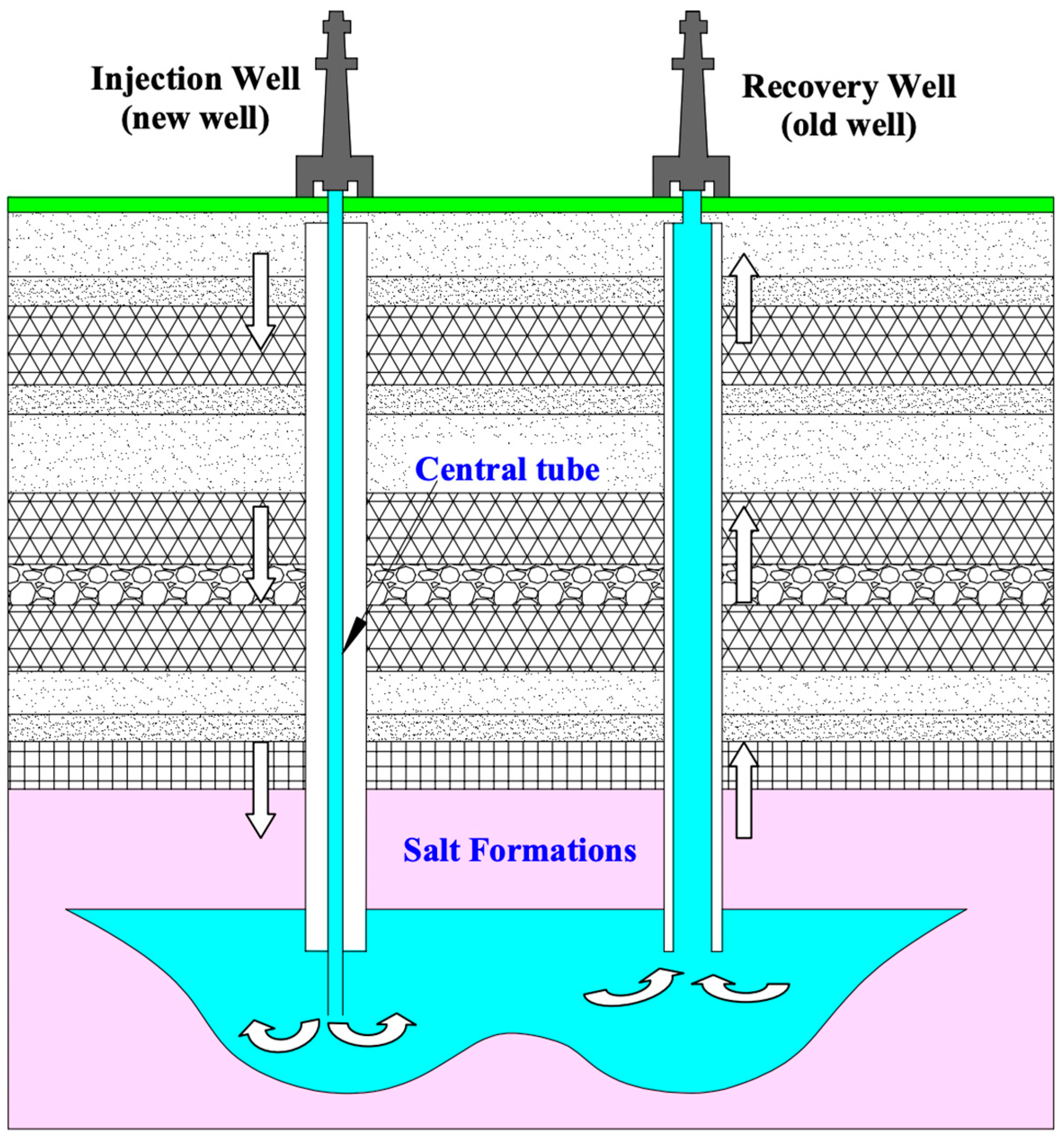
3.3.2. Solution Mining
3.3.3. Cyclic Loading
3.3.4. Abandonment
4. Conclusions and Future Research
- Salt caverns have been used for storage purposes due to their unique properties. However, exploring additional evaporite beds, such as potash and trona, could expand opportunities for energy storage.
- The mineralogy of salt, potash, and trona caverns plays an important role in their physical and mechanical behavior. While the mineralogy of these beds is well understood, more studies focusing on physical and mechanical properties are necessary for broader applications.
- It is important to understand how different physical and mechanical properties affect solution mining and the stability of caverns in different evaporite beds. Reliable data on density, porosity, and permeability in potash and trona beds are currently limited and should be prioritized.
- Developing innovative design approaches compatible with the nature of bedded salts will improve storage functionality and practicality.
- Geochemical aspects, alongside geomechanical factors, are critical for cavern stability and must be considered in the design, operation, and abandonment phases.
- Although this study focused on three evaporite deposit types, future research should address how the characteristics of stored materials influence evaporite properties.
- Investigating geochemical reactions and microbial effects on cavern integrity in different bedded evaporites is recommended, considering the specific mineralogy, type of stored gas, and in situ microbial communities.
- Coupling these geochemical insights with geomechanical consideration will offer a broader perspective on cavern integrity in various bedded evaporites, which is an essential gap to be addressed in future research.
Funding
Conflicts of Interest
References
- Bünger, U.; Michalski, J.; Crotogino, F.; Kruck, O. Large-Scale Underground Storage of Hydrogen for the Grid Integration of Renewable Energy and Other Applications. In Compendium of Hydrogen Energy; Elsevier: Amsterdam, The Netherlands, 2016; pp. 133–163. ISBN 978-1-78242-364-5. [Google Scholar]
- KBB Kavernen Bau- und Betriebs GmbH; KBB, Inc. Evaluation of the Effects of Long-Term-Storage in Salt Caverns on the Physical and Chemical Properties of Certain Crude Oils and Distillate Fuel Oils; Final Report; U.S. Department of Energy, Office of Scientific and Technical Information: Oak Ridge, TN, USA, 1979. Available online: https://www.osti.gov/biblio/5720208 (accessed on 29 November 2024).
- Davis, R.M. National Strategic Petroleum Reserve. Science 1981, 213, 618–622. [Google Scholar] [CrossRef] [PubMed]
- Mokhatab, S.; Poe, W.A.; Mak, J.Y. Natural Gas Fundamentals. In Handbook of Natural Gas Transmission and Processing; Elsevier: Amsterdam, The Netherlands, 2015; pp. 1–36. ISBN 978-0-12-801499-8. [Google Scholar]
- Islam, M.R. Storage of Petroleum Fluids. In Pipelines; Elsevier: Amsterdam, The Netherlands, 2023; pp. 497–551. ISBN 978-0-12-820600-3. [Google Scholar]
- Salameh, Z. Energy Storage. In Renewable Energy System Design; Elsevier: Amsterdam, The Netherlands, 2014; pp. 201–298. ISBN 978-0-12-374991-8. [Google Scholar]
- Donadei, S.; Schneider, G.-S. Compressed Air Energy Storage. In Storing Energy; Elsevier: Amsterdam, The Netherlands, 2022; pp. 141–156. ISBN 978-0-12-824510-1. [Google Scholar]
- Langer, M. Use of Solution-Mined Caverns in Salt for Oil and Gas Storage and Toxic Waste Disposal in Germany. Eng. Geol. 1993, 35, 183–190. [Google Scholar] [CrossRef]
- Winterle, J.; Ofoegbu, G.; Pabalan, R.; Manepally, C.; Mintz, T.; Pearcy, E.; Smart, K.; McMurry, J.; Pauline, R.; Fedors, R. Geologic Disposal of High-Level Radioactive Waste in Salt Formations. Annu. Rev. Environ. Resour. 2012, 37, 79. [Google Scholar]
- Veil, J.A. New Information on Disposal of Oil Field Wastes in Salt Caverns; Argonne National Lab.: Washington, DC, USA, 1996. [Google Scholar]
- Xue, T.; Yang, C.; Li, Y.; Shi, X.; Ma, H.; Wei, X.; Liu, Z.; Deng, J. Disposal of Drilling Waste in Salt Mines in China. Sci. Total Environ. 2024, 912, 168746. [Google Scholar] [CrossRef]
- Bachu, S.; Dusseault, M.B. Underground Injection of Carbon Dioxide in Salt Beds. In Developments in Water Science; Elsevier: Amsterdam, The Netherlands, 2005; Volume 52, pp. 637–648. ISBN 978-0-444-52068-5. [Google Scholar]
- Zhang, X.; Liu, W.; Chen, J.; Jiang, D.; Fan, J.; Daemen, J.J.K.; Qiao, W. Large-Scale CO2 Disposal/Storage in Bedded Rock Salt Caverns of China: An Evaluation of Safety and Suitability. Energy 2022, 249, 123727. [Google Scholar] [CrossRef]
- Mwakipunda, G.C.; Mgimba, M.M.; Ngata, M.R.; Yu, L. Recent Advances on Carbon Dioxide Sequestration Potentiality in Salt Caverns: A Review. Int. J. Greenh. Gas Control 2024, 133, 104109. [Google Scholar] [CrossRef]
- Caglayan, D.G.; Weber, N.; Heinrichs, H.U.; Linßen, J.; Robinius, M.; Kukla, P.A.; Stolten, D. Technical Potential of Salt Caverns for Hydrogen Storage in Europe. Int. J. Hydrogen Energy 2020, 45, 6793–6805. [Google Scholar] [CrossRef]
- Williams, J.D.O.; Williamson, J.P.; Parkes, D.; Evans, D.J.; Kirk, K.L.; Sunny, N.; Hough, E.; Vosper, H.; Akhurst, M.C. Does the United Kingdom Have Sufficient Geological Storage Capacity to Support a Hydrogen Economy? Estimating the Salt Cavern Storage Potential of Bedded Halite Formations. J. Energy Storage 2022, 53, 105109. [Google Scholar] [CrossRef]
- Ruiz Maraggi, L.M.; Moscardelli, L.G. Hydrogen Storage Potential of Salt Domes in the Gulf Coast of the United States. J. Energy Storage 2024, 82, 110585. [Google Scholar] [CrossRef]
- Lux, K.-H. Design of Salt Caverns for the Storage of Natural Gas, Crude Oil and Compressed Air: Geomechanical Aspects of Construction, Operation and Abandonment. Geol. Soc. Lond. Spec. Publ. 2009, 313, 93–128. [Google Scholar] [CrossRef]
- Firme, P.A.L.P.; Roehl, D.; Romanel, C. Salt Caverns History and Geomechanics towards Future Natural Gas Strategic Storage in Brazil. J. Nat. Gas Sci. Eng. 2019, 72, 103006. [Google Scholar] [CrossRef]
- Zhao, K.; Liu, Y.; Li, Y.; Ma, H.; Hou, W.; Yu, C.; Liu, H.; Feng, C.; Yang, C. Feasibility Analysis of Salt Cavern Gas Storage in Extremely Deep Formation: A Case Study in China. J. Energy Storage 2022, 47, 103649. [Google Scholar] [CrossRef]
- Li, H.; Wanyan, Q.; Ding, G.; Li, K.; Kou, Y.; Bai, S.; Ran, L.; Wu, J.; Deng, J. Geomechanical Feasibility Analysis of Salt Cavern Gas Storage Construction in Sanshui Basin, Guangdong Province. Eng 2022, 3, 709–731. [Google Scholar] [CrossRef]
- Li, H.; Ma, H.; Zhao, K.; Zhu, S.; Yang, K.; Zeng, Z.; Zheng, Z.; Yang, C. Parameter Design of the Compressed Air Energy Storage Salt Cavern in Highly Impure Rock Salt Formations. Energy 2024, 286, 129520. [Google Scholar] [CrossRef]
- Taiwo, G.O.; Tomomewo, O.S.; Oni, B.A. A Comprehensive Review of Underground Hydrogen Storage: Insight into Geological Sites (Mechanisms), Economics, Barriers, and Future Outlook. J. Energy Storage 2024, 90, 111844. [Google Scholar] [CrossRef]
- Malki, M.L.; Chellal, H.; Mao, S.; Rasouli, V.; Mehana, M. A Critical Review of Underground Hydrogen Storage: From Fundamentals to Applications, Unveiling Future Frontiers in Energy Storage. Int. J. Hydrogen Energy 2024, 79, 1365–1394. [Google Scholar] [CrossRef]
- Liu, W.; Zhang, X.; Wan, J.; Yang, C.; Jiang, L.; Chen, Z.; Jurado, M.J.; Shi, X.; Jiang, D.; Ji, W.; et al. Large-Scale Carbon Dioxide Storage in Salt Caverns: Evaluation of Operation, Safety, and Potential in China. Engineering 2024, 40, 226–246. [Google Scholar] [CrossRef]
- Liu, W.; Li, Q.; Yang, C.; Shi, X.; Wan, J.; Jurado, M.J.; Li, Y.; Jiang, D.; Chen, J.; Qiao, W.; et al. The Role of Underground Salt Caverns for Large-Scale Energy Storage: A Review and Prospects. Energy Storage Mater. 2023, 63, 103045. [Google Scholar] [CrossRef]
- Miocic, J.; Heinemann, N.; Edlmann, K.; Scafidi, J.; Molaei, F.; Alcalde, J. Underground Hydrogen Storage: A Review. Geol. Soc. Lond. Spec. Publ. 2023, 528, 73–86. [Google Scholar] [CrossRef]
- Thiyagarajan, S.R.; Emadi, H.; Hussain, A.; Patange, P.; Watson, M. A Comprehensive Review of the Mechanisms and Efficiency of Underground Hydrogen Storage. J. Energy Storage 2022, 51, 104490. [Google Scholar] [CrossRef]
- Raza, A.; Arif, M.; Glatz, G.; Mahmoud, M.; Al Kobaisi, M.; Alafnan, S.; Iglauer, S. A Holistic Overview of Underground Hydrogen Storage: Influencing Factors, Current Understanding, and Outlook. Fuel 2022, 330, 125636. [Google Scholar] [CrossRef]
- Muhammed, N.S.; Haq, B.; Al Shehri, D.; Al-Ahmed, A.; Rahman, M.M.; Zaman, E. A Review on Underground Hydrogen Storage: Insight into Geological Sites, Influencing Factors and Future Outlook. Energy Rep. 2022, 8, 461–499. [Google Scholar] [CrossRef]
- Sambo, C.; Dudun, A.; Samuel, S.A.; Esenenjor, P.; Muhammed, N.S.; Haq, B. A Review on Worldwide Underground Hydrogen Storage Operating and Potential Fields. Int. J. Hydrogen Energy 2022, 47, 22840–22880. [Google Scholar] [CrossRef]
- Aftab, A.; Hassanpouryouzband, A.; Xie, Q.; Machuca, L.L.; Sarmadivaleh, M. Toward a Fundamental Understanding of Geological Hydrogen Storage. Ind. Eng. Chem. Res. 2022, 61, 3233–3253. [Google Scholar] [CrossRef]
- Tarkowski, R.; Uliasz-Misiak, B. Towards Underground Hydrogen Storage: A Review of Barriers. Renew. Sustain. Energy Rev. 2022, 162, 112451. [Google Scholar] [CrossRef]
- AbuAisha, M.; Billiotte, J. A Discussion on Hydrogen Migration in Rock Salt for Tight Underground Storage with an Insight into a Laboratory Setup. J. Energy Storage 2021, 38, 102589. [Google Scholar] [CrossRef]
- Zivar, D.; Kumar, S.; Foroozesh, J. Underground Hydrogen Storage: A Comprehensive Review. Int. J. Hydrogen Energy 2021, 46, 23436–23462. [Google Scholar] [CrossRef]
- Tarkowski, R. Underground Hydrogen Storage: Characteristics and Prospects. Renew. Sustain. Energy Rev. 2019, 105, 86–94. [Google Scholar] [CrossRef]
- Tackie-Otoo, B.N.; Haq, M.B. A Comprehensive Review on Geo-Storage of H2 in Salt Caverns: Prospect and Research Advances. Fuel 2024, 356, 129609. [Google Scholar] [CrossRef]
- Tarifard, A.; Török, Á.; Görög, P. Review of the Creep Constitutive Models for Rocks and the Application of Creep Analysis in Geomechanics. Rock Mech. Rock Eng. 2024, 57, 7727–7757. [Google Scholar] [CrossRef]
- Ramesh Kumar, K.; Honorio, H.; Chandra, D.; Lesueur, M.; Hajibeygi, H. Comprehensive Review of Geomechanics of Underground Hydrogen Storage in Depleted Reservoirs and Salt Caverns. J. Energy Storage 2023, 73, 108912. [Google Scholar] [CrossRef]
- Vandeginste, V.; Ji, Y.; Buysschaert, F.; Anoyatis, G. Mineralogy, Microstructures and Geomechanics of Rock Salt for Underground Gas Storage. Deep Undergr. Sci. Eng. 2023, 2, 129–147. [Google Scholar] [CrossRef]
- Minougou, J.D.; Gholami, R.; Andersen, P. Underground Hydrogen Storage in Caverns: Challenges of Impure Salt Structures. Earth-Sci. Rev. 2023, 247, 104599. [Google Scholar] [CrossRef]
- Cyran, K. The Influence of Impurities and Fabrics on Mechanical Properties of Rock Salt for Underground Storage in Salt Caverns—A Review. Arch. Min. Sci. 2021, 66, 155–179. [Google Scholar] [CrossRef]
- Małachowska, A.; Łukasik, N.; Mioduska, J.; Gębicki, J. Hydrogen Storage in Geological Formations—The Potential of Salt Caverns. Energies 2022, 15, 5038. [Google Scholar] [CrossRef]
- Zhang, Q.; Song, Z.; Wang, J.; Zhang, Y.; Wang, T. Creep Properties and Constitutive Model of Salt Rock. Adv. Civ. Eng. 2021, 2021, 8867673. [Google Scholar] [CrossRef]
- Cerfontaine, B.; Collin, F. Cyclic and Fatigue Behaviour of Rock Materials: Review, Interpretation and Research Perspectives. Rock Mech. Rock Eng. 2018, 51, 391–414. [Google Scholar] [CrossRef]
- Bruno, M.; Dorfmann, L.; Han, G.; Lao, K.; Young, J. 3D Geomechanical Analysis of Multiple Caverns in Bedded Salt. In Proceedings of the SMRI Fall Technical Meeting, Nancy, France, 1–5 October 2005. [Google Scholar]
- Sheikheh, S.; Rabiei, M.; Rasouli, V. Comparison of Salt and Trona Caverns for Hydrogen Storage. In Proceedings of the SMRI Spring 2023 Technical Conference, Detroit, MI, USA, 23–26 April 2023. [Google Scholar]
- Schwab, F.L. Sedimentary Petrology. In Encyclopedia of Physical Science and Technology; Elsevier: Amsterdam, The Netherlands, 2003; pp. 495–529. ISBN 978-0-12-227410-7. [Google Scholar]
- Sonnenfeld, P. Evaporites. In Encyclopedia of Physical Science and Technology; Elsevier: Amsterdam, The Netherlands, 2003; pp. 653–671. ISBN 978-0-12-227410-7. [Google Scholar]
- Selley, R.C. Mineralogy and Classification. In Encyclopedia of Geology; Elsevier: Amsterdam, The Netherlands, 2005; pp. 655–665. ISBN 978-0-08-102909-1. [Google Scholar]
- Warren, J.K. Evaporite Deposits. In Encyclopedia of Geology; Elsevier: Amsterdam, The Netherlands, 2021; pp. 945–977. ISBN 978-0-08-102909-1. [Google Scholar]
- Elias, S.A. Introduction to Paleoclimates. In Encyclopedia of Geology; Elsevier: Amsterdam, The Netherlands, 2021; pp. 288–298. ISBN 978-0-08-102909-1. [Google Scholar]
- Scruton, P.C. Deposition of Evaporites. AAPG Bull. 1953, 37, 2498–2512. [Google Scholar] [CrossRef]
- Hsu, K.J. Origin of Saline Giants: A Critical Review after the Discovery of the Mediterranean Evaporite. Earth-Sci. Rev. 1972, 8, 371–396. [Google Scholar] [CrossRef]
- Lorenz, J.; Haas, J.L., Jr.; Clynne, M.A.; Potter, R.W.; Schafer, C.M. Chapter 1: Geology, Mineralogy, and Some Geophysical and Geochemical Properties of Salt Deposits. In Physical Properties Data for Rock Salt; National Bureau of Standards, U.S. Government Printing Office: Washington, DC, USA, 1981; Volume 167. [Google Scholar]
- Jeremic, M.L. 1. General Geology. In Rock Mechanics in Salt Mining; Balkema: Rotterdam, The Netherlands, 1994; ISBN 978-90-5410-113-0. [Google Scholar]
- Moore, G.W. Origin and Chemical Composition of Evaporite Deposits; U.S. Geological Survey: Reston, VA, USA, 1960. [Google Scholar]
- Mann, P.; Mclaughlin, P.P., Jr.; Bold, W.A.V.D.; Lawrence, S.R.; Lamar, M.E. Chapter 12 Tectonic and Eustatic Controls on Neogene Evaporitic and Siliciclastic Deposition in the Enriquillo Basin, Dominican Republic. In Sedimentary Basins of the World; Elsevier: Amsterdam, The Netherlands, 1999; Volume 4, pp. 287–342. ISBN 978-0-444-82649-7. [Google Scholar]
- Babasafari, A.A.; Ghosh, D.P.; Ratnam, T.; Rezaei, S.; Sambo, C. Geological Reservoir Modeling and Seismic Reservoir Monitoring. In Seismic Imaging Methods and Applications for Oil and Gas Exploration; Elsevier: Amsterdam, The Netherlands, 2022; pp. 179–285. ISBN 978-0-323-91946-3. [Google Scholar]
- Warren, J.K. Evaporites through Time: Tectonic, Climatic and Eustatic Controls in Marine and Nonmarine Deposits. Earth-Sci. Rev. 2010, 98, 217–268. [Google Scholar] [CrossRef]
- Warren, J. Evaporites. In Encyclopedia of Geochemistry; White, W.M., Ed.; Encyclopedia of Earth Sciences Series; Springer International Publishing: Cham, Switzerland, 2016; pp. 1–8. ISBN 978-3-319-39193-9. [Google Scholar]
- Smoot, J.P.; Lowenstein, T.K. Chapter 3 Depositional Environments of Non-Marine Evaporites. In Developments in Sedimentology; Elsevier: Amsterdam, The Netherlands, 1991; Volume 50, pp. 189–347. ISBN 978-0-444-88680-4. [Google Scholar]
- Bąbel, M.; Schreiber, B.C. Geochemistry of Evaporites and Evolution of Seawater. In Treatise on Geochemistry; Elsevier: Amsterdam, The Netherlands, 2014; pp. 483–560. ISBN 978-0-08-098300-4. [Google Scholar]
- Schreiber, B.C.; Tabakh, M.E. Deposition and Early Alteration of Evaporites. Sedimentology 2000, 47, 215–238. [Google Scholar] [CrossRef]
- Friedman, G.M. Depositional Environment of Evaporite Deposits. In Marine Evaporites; Dean, W.E., Schreiber, B.C., Dean, W.E., Friedman, G.M., Hite, R.J., Nurmi, R.D., Raup, O.B., Schreiber, B.C., Shearman, D.J., Eds.; SEPM (Society for Sedimentary Geology): Tulsa, OK, USA, 1978; ISBN 978-1-56576-233-6. [Google Scholar]
- Sloss, L.L. The Significance of Evaporites. SEPM J. Sediment. Res. 1953, 23, 143–161. [Google Scholar] [CrossRef]
- Magaritz, M. A New Explanation for Cyclic Deposition in Marine Evaporite Basins: Meteoric Water Input. Chem. Geol. 1987, 62, 239–250. [Google Scholar] [CrossRef]
- Gerdes, G.; Krumbein, W.E.; Noffke, N. Evaporite Microbial Sediments. In Microbial Sediments; Riding, R.E., Awramik, S.M., Eds.; Springer: Berlin/Heidelberg, Germany, 2000; pp. 196–208. ISBN 978-3-642-08275-7. [Google Scholar]
- Taher, A.G. Microbially Induced Sedimentary Structures in Evaporite–Siliciclastic Sediments of Ras Gemsa Sabkha, Red Sea Coast, Egypt. J. Adv. Res. 2014, 5, 577–586. [Google Scholar] [CrossRef]
- Perillo, V.L.; Maisano, L.; Martinez, A.M.; Quijada, I.E.; Cuadrado, D.G. Microbial Mat Contribution to the Formation of an Evaporitic Environment in a Temperate-Latitude Ecosystem. J. Hydrol. 2019, 575, 105–114. [Google Scholar] [CrossRef]
- Hardie, L.A.; Eugster, H.P. The Depositional Environment of Marine Evaporites: A Case for Shallow, Clastic Accumulation. Sedimentology 1971, 16, 187–220. [Google Scholar] [CrossRef]
- Robertson Handford, C. Coastal Sabkha and Salt Pan Deposition of the Lower Clear Fork Formation (Permian), Texas. SEPM J. Sediment. Res. 1981, 51, 761–778. [Google Scholar] [CrossRef]
- Hovorka, S. Depositional Environments of Marine-Dominated Bedded Halite, Permian San Andres Formation, Texas. Sedimentology 1987, 34, 1029–1054. [Google Scholar] [CrossRef]
- Lowenstein, T.K. Origin of Depositional Cycles in a Permian “Saline Giant”: The Salado (McNutt Zone) Evaporites of New Mexico and Texas. Geol. Soc. Am. Bull. 1988, 100, 592–608. [Google Scholar] [CrossRef]
- Dellwig, L.F.; Evans, R. Depositional Processes in Salina Salt of Michigan, Ohio, and New York. AAPG Bull. 1969, 53, 949–956. [Google Scholar] [CrossRef]
- Brodylo, L.A.; Spencer, R.J. Depositional Environment of The Middle Devonian Telegraph Salts, Alberta, Canada. Bull. Can. Pet. Geol. 1987, 35, 186–196. [Google Scholar]
- Baillie, A.D. Devonian System of Williston Basin. AAPG Bull. 1955, 39, 575–629. [Google Scholar] [CrossRef]
- Klingspor, A.M. Cyclic Deposits of Potash in Saskatchewan. Bull. Can. Pet. Geol. 1966, 14, 193–207. [Google Scholar] [CrossRef]
- Dyni, J.R.; Wiig, S.V.; Grundy, W.D. Trona Resources in Southwest Wyoming. Nonrenew. Resour. 1995, 4, 340–352. [Google Scholar] [CrossRef]
- Schmalz, R.F. Deep-Water Evaporite Deposition: A Genetic Model. AAPG Bull. 1969, 53, 798–823. [Google Scholar] [CrossRef]
- Taberner, C.; Cendo, D.I.; Pueyo, J.J.; Ayora, C. The Use of Environmental Markers to Distinguish Marine vs. Continental Deposition and to Quantify the Significance of Recycling in Evaporite Basins. Sediment. Geol. 2000, 137, 213–240. [Google Scholar] [CrossRef]
- Topper, R.P.M.; Meijer, P.T. A Modeling Perspective on Spatial and Temporal Variations in Messinian Evaporite Deposits. Mar. Geol. 2013, 336, 44–60. [Google Scholar] [CrossRef]
- Nurmi, R.D.; Friedman, G.M. Sedimentology and Depositional Environments of Basin-Center Evaporites, Lower Salina Group (Upper Silurian), Michigan Basin. In Reefs and Evaporites—Concepts and Depositional Models; American Association of Petroleum Geologists: Tulsa, OK, USA, 1977; pp. 23–52. ISBN 978-0-89181-009-4. [Google Scholar]
- Sloss, L.L. Evaporite Deposition from Layered Solutions. AAPG Bull. 1969, 53, 776–789. [Google Scholar] [CrossRef]
- Hardie, L.A. The Origin of the Recent Non-Marine Evaporite Deposit of Saline Valley, Inyo County, California. Geochim. Cosmochim. Acta 1968, 32, 1279–1301. [Google Scholar] [CrossRef]
- Teixeira, L.; Lupinacci, W.M.; Maul, A. Quantitative Seismic-Stratigraphic Interpretation of the Evaporite Sequence in the Santos Basin. Mar. Pet. Geol. 2020, 122, 104690. [Google Scholar] [CrossRef]
- Tay, P.L.; Lonergan, L.; Warner, M.; Jones, K.A. Seismic Investigation of Thick Evaporite Deposits on the Central and Inner Unit of the Mediterranean Ridge Accretionary Complex. Mar. Geol. 2002, 186, 167–194. [Google Scholar] [CrossRef]
- Güneş, P.; Aksu, A.E.; Hall, J. Internal Seismic Stratigraphy of the Messinian Evaporites across the Northern Sector of the Eastern Mediterranean Sea. Mar. Pet. Geol. 2018, 91, 297–320. [Google Scholar] [CrossRef]
- Stratigraphic Variations Control Deformation Patterns in Evaporite Basins: Messinian Examples, Onshore and Offshore Sicily (Italy). Available online: https://www.lyellcollection.org/doi/epub/10.1144/jgs2014-024 (accessed on 5 November 2024).
- Dean, W.E.; Schreiber, B.C.; Nurmi, R.D. (Eds.) Marine Evaporites; SEPM (Society for Sedimentary Geology): Tulsa, OK, USA, 1978; ISBN 978-1-56576-233-6. [Google Scholar]
- Saner, S.; Abdulghani, W.M. Lithostratigraphy and Depositional Environments of the Upper Jurassic Arab-C Carbonate and Associated Evaporites in the Abqaiq Field, Eastern Saudi Arabia. AAPG Bull. 1995, 79, 394–409. [Google Scholar] [CrossRef]
- Hardie, L.W.A.; Eugster, H.P. The Evolution of Closed-Basin Brines. Mineral. Soc. Amer. Spec. Pap. 1970, 3, 273–290. [Google Scholar]
- Hardie, L.A. Evaporites; Marine or Non-Marine? Am. J. Sci. 1984, 284, 193–240. [Google Scholar] [CrossRef]
- Lugli, S. Evaporites. In Encyclopedia of Paleoclimatology and Ancient Environments; Gornitz, V., Ed.; Encyclopedia of Earth Sciences Series; Springer: Dordrecht, The Netherlands, 2009; pp. 321–325. ISBN 978-1-4020-4551-6. [Google Scholar]
- Warren, J.K. Evaporites: A Geological Compendium; Springer International Publishing: Cham, Switzerland, 2016; ISBN 978-3-319-13511-3. [Google Scholar]
- Warren, J.K. Evaporites, Brines and Base Metals: What Is an Evaporite? Defining the Rock Matrix. Aust. J. Earth Sci. 1996, 43, 115–132. [Google Scholar] [CrossRef]
- Warren, J.K. Evaporites, Brines and Base Metals: Fluids, Flow and ‘the Evaporite That Was’. Aust. J. Earth Sci. 1997, 44, 149–183. [Google Scholar] [CrossRef]
- Renaut, R.W.; Last, W.M. (Eds.) Sedimentology and Geochemistry of Modern and Ancient Saline Lakes; SEPM (Society for Sedimentary Geology): Tulsa, OK, USA, 1994; ISBN 978-1-56576-014-1. [Google Scholar]
- Gu, J.; Chen, A.; Song, G.; Wang, X. Evaporite Deposition since Marine Isotope Stage 7 in Saline Lakes of the Western Qaidam Basin, NE Qinghai-Tibetan Plateau. Quat. Int. 2022, 613, 14–23. [Google Scholar] [CrossRef]
- Getenet, M.; García-Ruiz, J.M.; Otálora, F.; Emmerling, F.; Al-Sabbagh, D.; Verdugo-Escamilla, C. A Comprehensive Methodology for Monitoring Evaporitic Mineral Precipitation and Hydrochemical Evolution of Saline Lakes: The Case of Lake Magadi Soda Brine (East African Rift Valley, Kenya). Cryst. Growth Des. 2022, 22, 2307–2317. [Google Scholar] [CrossRef]
- Soltaninejad, A.; Ranjbar, H.; Honarmand, M.; Dargahi, S. Evaporite Mineral Mapping and Determining Their Source Rocks Using Remote Sensing Data in Sirjan Playa, Kerman, Iran. Carbonates Evaporites 2018, 33, 255–274. [Google Scholar] [CrossRef]
- Phalen, W.C. Salt Resources of the United States. 1919. Available online: https://pubs.usgs.gov/publication/b669 (accessed on 29 November 2024).
- Orris, G.J.; Cocker, M.D.; Dunlap, P.; Wynn, J.C.; Spanski, G.T.; Briggs, D.A.; Gass, L.; Bliss, J.D.; Bolm, K.S.; Yang, C.; et al. Potash—A Global Overview of Evaporite-Related Potash Resources, Including Spatial Databases of Deposits, Occurrences, and Permissive Tracts; Scientific Investigations Report; U.S. Geological Survey: Reston, VA, USA, 2014. Available online: https://pubs.usgs.gov/publication/sir20105090S (accessed on 29 November 2024).
- Wiig, S.V.; Grundy, W.D.; Dyni, J.R. Trona Resources in The Green River Basin, Southwest Wyoming; Open-File Report; U.S. Geological Survey: Reston, VA, USA, 1995. [Google Scholar]
- Warren, J.K. Evaporites: Sediments, Resources and Hydrocarbons; Springer: Berlin/Heidelberg, Germany; New York, NY, USA, 2006; ISBN 978-3-540-26011-0. [Google Scholar]
- Speight, J.G. Recovery, Storage, and Transportation. In Natural Gas; Elsevier: Amsterdam, The Netherlands, 2019; pp. 149–186. ISBN 978-0-12-809570-6. [Google Scholar]
- Li, J.; Yang, C.; Shi, X.; Xu, W.; Li, Y.; Daemen, J.J.K. Construction Modeling and Shape Prediction of Horizontal Salt Caverns for Gas/Oil Storage in Bedded Salt. J. Pet. Sci. Eng. 2020, 190, 107058. [Google Scholar] [CrossRef]
- Johnson, K.S.; Gonzales, S. Salt Deposits in the United States and Regional Geologic Characteristics Important for Storage of Radioactive Waste; U.S. Department of Energy: Norman, OK, USA, 2018. [Google Scholar]
- Pearson, W.J. Salt Deposits of Canada 1962; Solution Mining Research Institute (SMRI): Clifton Park, NY, USA, 1962. [Google Scholar]
- Lefond, S.J.J. Handbook of World Salt Resources, 1st ed.; Springer: New York, NY, USA, 1969; ISBN 978-1-4684-0705-1. [Google Scholar]
- Horváth, P.L.; Mirau, S.; Schneider, G.-S.; Bernhardt, H.; Weiler, C.; Bödeker, J.; Wippich, M.; Tangermann, T.; Ratigan, J. Update of SMRI’s Compilation of Worldwide Salt Deposits and Salt Cavern Fields; Solution Mining Research Institute: Clifton Park, NY, USA, 2018. [Google Scholar]
- Johnson, K.S.; Gonzales, S. Geology and Salt Deposits of the Michigan Basin; Office of Waste Isolation, Union Carbide Corp.: Oak Ridge, TN, USA, 1976; p. Y/OWI/SUB-4494/2. [Google Scholar]
- Harrison, W.B., III; Voice, P.J. Evaporite Facies of the Michigan Basin. In Paleozoic Stratigraphy and Resources of the Michigan Basin; Grammer, G.M., Harrison, W.B., Barnes, D.A., Eds.; Geological Society of America: Boulder, CO, USA, 2018; pp. 197–216. ISBN 978-0-8137-2531-4. [Google Scholar]
- Landes, K.K. Detroit River Group in the Michigan Basin; Circular; United States Department of the Interior: Washington, DC, USA, 1951. [Google Scholar]
- Pierce, W.G.; Rich, E.I. Summary of Rock Salt Deposits in the United States as Possible Storage Sites for Radioactive Waste Materials; U.S. Atomic Energy Commission: Washington, DC, USA, 1962. [Google Scholar]
- Hite, R.J.; Lohman, S.W. Geologic Appraisal of Paradox Basin Salt Deposits for Waste Emplacement; U.S. Geological Survey: Denver, CO, USA, 1973. [Google Scholar]
- Sandberg, C.A. Geology of the Williston Basin, North Dakota, Montana, and South Dakota, with Reference to Subsurface Disposal of Radioactive Wastes; United States Department of the Interior: Washington, DC, USA, 1962. [Google Scholar] [CrossRef]
- Lefever, J.A.; Lefever, R.D. Salts in the Williston Basin, North Dakota; North Dakota Geological Survey: Bismarck, ND, USA, 2005. [Google Scholar]
- Martin, C.A. Denver Basin. Bull. Am. Assoc. Pet. Geol. 1965, 49, 1908–1923. [Google Scholar] [CrossRef]
- Oldham, D.W. Permian Salt in the Northern Denver Basin: Controls on Occurrence and Relationship to Oil and Gas Production from Cretaceous Reservoirs. In Paleozoic Systems of the Rocky Mountain Region; SEPM (Society for Sedimentary Geology): Tulsa, OK, USA, 1996. [Google Scholar]
- Darton, N.H. Permian Salt Deposits of the South-Central United States. In Contributions to Economic Geology; Government Feinting Office: Washington, DC, USA, 1920. [Google Scholar]
- Schulmeister, M.K.; Andeskie, A.S.; Benison, K.C. The Science and Industry of the Permian Hutchinson Salt. In Exploring Extreme and Unusual Geology in the Stable Midcontinent: Field Excursions for the 2019 GSA South-Central, North-Central, and Rocky Mountain Sections Joint Meeting; Schulmeister, M.K., Aber, J.S., Eds.; Geological Society of America: Boulder, CO, USA, 2019; pp. 25–36. ISBN 978-0-8137-0052-6. [Google Scholar]
- Jones, C.L. Salt Deposits of the Clovis-Portales Area, East-Central New Mexico; Open-File Report; U.S. Geological Survey: Reston, VA, USA, 1974. [Google Scholar]
- Kroenlein, G.A. Salt, Potash, and Anhydrite in Castile Formation of Southeast New Mexico. AAPG Bull. 1939, 23, 1682–1693. [Google Scholar] [CrossRef]
- Lang, W.B. Salado Formation of the Permian Basin: GEOLOGICAL NOTES. AAPG Bull. 1939, 23, 1569–1572. [Google Scholar] [CrossRef]
- Neal, J.T. Supai Salt Karst Features: Holbrook Basin, Arizona; Routledge: Oxfordshire, UK, 1994. [Google Scholar]
- Gorecki, C.D.; Sorensen, J.A.; Steadman, E.; Harju, J.A. CO2 Storage Risk Minimization through Systematic Identification and Assessment of Faults: A Williston Basin Case Study. Energy Procedia 2009, 1, 2887–2894. [Google Scholar] [CrossRef]
- Canadian Minerals Yearbook 2008; Natural Resources Canada: Ottawa, ON, Canada, 2008; Available online: https://publications.gc.ca/collections/collection_2010/nrcan/M38-5-57-eng.pdf (accessed on 29 November 2024).
- Cocker, M.D.; Orris, G.J.; Dunlap, P.; Yang, C.; Bliss, J.D. Geology and Undiscovered Resource Assessment of the Potash-Bearing, Middle Devonian (Givetian), Prairie Evaporite, Elk Point Basin, Canada and United States; Scientific Investigations Report; U.S. Geological Survey: Reston, VA, USA, 2023. Available online: https://pubs.usgs.gov/publication/sir20105090CC (accessed on 29 November 2024).
- Dyni, J.R. Sodium Carbonate Resources of the Green River Formation; Open-File Report; U.S. Geological Survey: Reston, VA, USA, 1997. [Google Scholar]
- Cyran, K. Insight into a Shape of Salt Storage Caverns. Arch. Min. Sci. 2020, 65, 363–398. [Google Scholar] [CrossRef]
- Schön, J.H. Density. In Developments in Petroleum Science; Elsevier: Amsterdam, The Netherlands, 2015; Volume 65, pp. 109–118. ISBN 978-0-08-100404-3. [Google Scholar]
- Giambastiani, M. Geomechanical Characterization of Evaporitic Rocks. In Soft Rock Mechanics and Engineering; Kanji, M., He, M., Ribeiro, E., Sousa, L., Eds.; Springer International Publishing: Cham, Switzerland, 2020; pp. 129–161. ISBN 978-3-030-29476-2. [Google Scholar]
- DeFoe, O.K.; Compton, A.H. The Density of Rock Salt and Calcite. Phys. Rev. 1925, 25, 618–620. [Google Scholar] [CrossRef]
- Roedder, E. Fluid Inclusions. In Encyclopedia of Physical Science and Technology; Elsevier: Amsterdam, The Netherlands, 2003; pp. 71–77. ISBN 978-0-12-227410-7. [Google Scholar]
- Zhang, J.J. In Situ Stress Estimate. In Applied Petroleum Geomechanics; Elsevier: Amsterdam, The Netherlands, 2019; pp. 187–232. ISBN 978-0-12-814814-3. [Google Scholar]
- Speirs, D.C.D.; Bere, A.; Roberts, D. Geomechanical Modelling of Salt Caverns under Operational Loading from Hydrogen Storage. In Proceedings of the ARMA/DGS/SEG International Geomechanics Symposium, Abu Dhabi, United Arab Emirates, 7–10 November 2022; p. ARMA-IGS-2022-036. [Google Scholar]
- Fundamentals of Rock Properties. Available online: https://www.sciencedirect.com/science/article/pii/B9781856178037500122 (accessed on 29 November 2024).
- Liu, W.; Muhammad, N.; Chen, J.; Spiers, C.J.; Peach, C.J.; Deyi, J.; Li, Y. Investigation on the Permeability Characteristics of Bedded Salt Rocks and the Tightness of Natural Gas Caverns in Such Formations. J. Nat. Gas Sci. Eng. 2016, 35, 468–482. [Google Scholar] [CrossRef]
- Zhang, N.; Liu, W.; Zhang, Y.; Shan, P.; Shi, X. Microscopic Pore Structure of Surrounding Rock for Underground Strategic Petroleum Reserve (SPR) Caverns in Bedded Rock Salt. Energies 2020, 13, 1565. [Google Scholar] [CrossRef]
- Liang, C.; Liu, J.; Yang, J.; Xu, H.; Chen, Z.; Ran, L. A Creep Model for Ultra-Deep Salt Rock Considering Thermal-Mechanical Damage under Triaxial Stress Conditions. J. Rock Mech. Geotech. Eng. 2023, 16, 588–596. [Google Scholar] [CrossRef]
- Chen, J.; Li, E.; Luo, J. Characterization of Microscopic Pore Structures of Rock Salt through Mercury Injection and Nitrogen Absorption Tests. Geofluids 2018, 2018, 9427361. [Google Scholar] [CrossRef]
- Goldsmith, L.H. Some Fundamentals of Potash Geology as a Guide to Exploration. In Proceedings of the SPWLA 7th Annual Logging Symposium, Tulsa, Oklahoma, 9 May 1966; p. SPWLA-1966-O. [Google Scholar]
- Yang, C.; Chi, G. Quantitative Evaluation of Potash Grade and Mineralogy Based on Geophysical Well-Log Analysis: Preliminary Study of the Prairie Evaporite in Saskatchewan; Saskatchewan Ministry of Economy Miscellaneous: Regina, SK, Canada, 2013.
- Onargan, T.; Koca, M.Y.; Kucuk, K.; Deliormanli, A.; Saydam, S. Impact of the Mechanical Characteristics of Weak Rocks and Trona Ore Beds on the Main Drift Deformation at the Beypazari Mine, Turkey. Int. J. Rock Mech. Min. Sci. 2004, 41, 641–654. [Google Scholar] [CrossRef]
- Wei, L.; Jie, C.; Deyi, J.; Xilin, S.; Yinping, L.; Daemen, J.J.K.; Chunhe, Y. Tightness and Suitability Evaluation of Abandoned Salt Caverns Served as Hydrocarbon Energies Storage under Adverse Geological Conditions (AGC). Appl. Energy 2016, 178, 703–720. [Google Scholar] [CrossRef]
- Li, P.; Li, Y.; Shi, X.; Zhao, K.; Liu, X.; Ma, H.; Yang, C. Prediction Method for Calculating the Porosity of Insoluble Sediments for Salt Cavern Gas Storage Applications. Energy 2021, 221, 119815. [Google Scholar] [CrossRef]
- Meng, T.; Jianliang, P.; Feng, G.; Hu, Y.; Zhang, Z.; Zhang, D. Permeability and Porosity in Damaged Salt Interlayers under Coupled THMC Conditions. J. Pet. Sci. Eng. 2022, 211, 110218. [Google Scholar] [CrossRef]
- Fjær, E.; Holt, R.M.; Horsrud, P.; Raaen, A.M.; Risnes, R. Chapter 6 Rock Models. In Developments in Petroleum Science; Elsevier: Amsterdam, The Netherlands, 2008; Volume 53, pp. 219–250. ISBN 978-0-444-50260-5. [Google Scholar]
- Shad, S.; Razaghi, N.; Zivar, D.; Mellat, S. Mechanical Behavior of Salt Rocks: A Geomechanical Model. Petroleum 2023, 9, 508–525. [Google Scholar] [CrossRef]
- Chen, X.; Li, Y.; Shi, Y.; Yu, Y.; Jiang, Y.; Liu, Y.; Dong, J. Tightness and Stability Evaluation of Salt Cavern Underground Storage with a New Fluid–Solid Coupling Seepage Model. J. Pet. Sci. Eng. 2021, 202, 108475. [Google Scholar] [CrossRef]
- 3—Reservoir Rock Properties. Available online: https://www.sciencedirect.com/science/article/pii/B9780128002193000036?via%3Dihub (accessed on 29 November 2024).
- Zhang, L. Aspects of Rock Permeability. Front. Struct. Civ. Eng. 2013, 7, 102–116. [Google Scholar] [CrossRef]
- Pająk, L.; Lankof, L.; Tomaszewska, B.; Wojnarowski, P.; Janiga, D. The Development of the Temperature Disturbance Zone in the Surrounding of a Salt Cavern Caused by the Leaching Process for Safety Hydrogen Storage. Energies 2021, 14, 803. [Google Scholar] [CrossRef]
- Zhao, K.; Ma, H.; Li, Y.; Liu, Y.; Cai, R.; Liang, X.; Huang, S.; Zeng, Z.; Wang, X.; Li, H. Stability Evaluation of Horizontal Salt Caverns for Gas Storage in Two Mining Layers: A Case Study in China. Energies 2023, 16, 7288. [Google Scholar] [CrossRef]
- Lyu, C.; Liu, J.; Ren, Y.; Liang, C.; Zeng, Y. Mechanical Characteristics and Permeability Evolution of Salt Rock under Thermal-Hydro-Mechanical (THM) Coupling Condition. Eng. Geol. 2022, 302, 106633. [Google Scholar] [CrossRef]
- Liang, X.; Meng, T.; Feng, G.; Zhao, G.; Wang, Z.; Liu, P. Evolution of Permeability and Pore Structure of Salt Rock and Its Self-Healing Mechanism under Coupled Thermo-Hydro-Mechanical Environment. J. Energy Storage 2023, 66, 107476. [Google Scholar] [CrossRef]
- Daniels, J.J.; Scott, J.H.; Hite, R.J. Analysis of Borehole Geophysical Data in an Evaporite Sequence at Salt Valley, Utah; Open-File Report; USGS: Reston, VA, USA, 1980. [Google Scholar]
- Culbertson, W.C. Stratigraphy of the Trona Deposits in the Green River Formation, Southwest Wyoming. Rocky Mt. Geol. 1971, 10, 15–23. [Google Scholar]
- Mannion, L.E. The Trona Deposits of Southwest Wyoming. In Geologic Guidebook of the Uinta Mountains: Utah’s Maverick Range; Utah Geological Association: Salt Lake City, Utah, USA, 1969. [Google Scholar]
- Alger, R.P.; Crain, E.R. Defining Evaporite Deposites with Electrical Well Logs. Raymer, L.L., Hoyle, W.R., Tixier, M.P., Eds.; Northern Ohio Geological Society: Cleveland, OH, USA, 1966; Volume 2, pp. 116–130. [Google Scholar]
- Peng, S.; Zhang, J.J. Engineering Geology for Underground Rocks; Springer: Berlin/Heidelberg, Germany, 2007; ISBN 978-3-540-73294-5. [Google Scholar]
- Belyadi, H.; Fathi, E.; Belyadi, F. Rock Mechanical Properties and in Situ Stresses. In Hydraulic Fracturing in Unconventional Reservoirs; Elsevier: Amsterdam, The Netherlands, 2019; pp. 215–231. ISBN 978-0-12-817665-8. [Google Scholar]
- Zhang, J.J. Rock Physical and Mechanical Properties. In Applied Petroleum Geomechanics; Elsevier: Amsterdam, The Netherlands, 2019; pp. 29–83. ISBN 978-0-12-814814-3. [Google Scholar]
- Małkowski, P.; Ostrowski, Ł. The Methodology for the Young Modulus Derivation for Rocks and Its Value. Procedia Eng. 2017, 191, 134–141. [Google Scholar] [CrossRef]
- Xu, X.; Huang, R.; Li, H.; Huang, Q. Determination of Poisson’s Ratio of Rock Material by Changing Axial Stress and Unloading Lateral Stress Test. Rock Mech. Rock Eng. 2015, 48, 853–857. [Google Scholar] [CrossRef]
- Dong, L.; Xu, H.; Fan, P.; Wu, Z. On the Experimental Determination of Poisson’s Ratio for Intact Rocks and Its Variation as Deformation Develops. Adv. Civ. Eng. 2021, 2021, 8843056. [Google Scholar] [CrossRef]
- Narimani, S.; Davarpanah, S.M.; Vásárhelyi, B. Estimation of the Poisson’s Ratio of the Rock Mass. Period. Polytech. Civ. Eng. 2024, 68, 274–288. [Google Scholar] [CrossRef]
- Tiab, D.; Donaldson, E.C. Effect of Stress on Reservoir Rock Properties. In Petrophysics; Elsevier: Amsterdam, The Netherlands, 2012; pp. 553–666. ISBN 978-0-12-383848-3. [Google Scholar]
- Xu, L.; Xu, X.; Sun, Y.; Lu, T. Evaluation of Rock Brittleness Based on Complete Stress–Strain Curve. Mathematics 2022, 10, 4470. [Google Scholar] [CrossRef]
- Mehranpour, M.H.; Kulatilake, P.H.S.W. Comparison of Six Major Intact Rock Failure Criteria Using a Particle Flow Approach under True-Triaxial Stress Condition. Geomech. Geophys. Geo-Energy Geo-Resour. 2016, 2, 203–229. [Google Scholar] [CrossRef]
- Aadnøy, B.S.; Looyeh, R. Failure Criteria. In Petroleum Rock Mechanics; Elsevier: Amsterdam, The Netherlands, 2019; pp. 53–62. ISBN 978-0-12-815903-3. [Google Scholar]
- Liang, W.; Zhang, C.; Gao, H.; Yang, X.; Xu, S.; Zhao, Y. Experiments on Mechanical Properties of Salt Rocks under Cyclic Loading. J. Rock Mech. Geotech. Eng. 2012, 4, 54–61. [Google Scholar] [CrossRef]
- Xing, W.; Zhao, J.; Düsterloh, U.; Brückner, D.; Hou, Z.; Xie, L.; Liu, J. Experimental Study of Mechanical and Hydraulic Properties of Bedded Rock Salt from the Jintan Location. Acta Geotech. 2014, 9, 145–151. [Google Scholar] [CrossRef]
- Bauer, S.J.; Song, B.; Sanborn, B. Dynamic Compressive Strength of Rock Salts. Int. J. Rock Mech. Min. Sci. 2019, 113, 112–120. [Google Scholar] [CrossRef]
- Chunhe, Y.; Yinping, L.; Feng, C.; Xilin, S.; Dan’an, Q. Advances in Researches of the Mechanical Behaviors of Deep Bedded Salt Rocks in China. In Proceedings of the 43rd U.S. Rock Mechanics Symposium & 4th U.S.–Canada Rock Mechanics Symposium, Asheville, NC, USA, 28 June–1 July 2009. [Google Scholar]
- Liang, W.; Yang, C.; Zhao, Y.; Dusseault, M.B.; Liu, J. Experimental Investigation of Mechanical Properties of Bedded Salt Rock. Int. J. Rock Mech. Min. Sci. 2007, 44, 400–411. [Google Scholar] [CrossRef]
- Istvan, J.A.; Evans, L.J.; Weber, J.H.; Devine, C. Rock Mechanics for Gas Storage in Bedded Salt Caverns. Int. J. Rock Mech. Min. Sci. 1997, 34, 142.e1-142.e12. [Google Scholar] [CrossRef]
- Guo, Y.; Yang, C.; Mao, H. Mechanical Properties of Jintan Mine Rock Salt under Complex Stress Paths. Int. J. Rock Mech. Min. Sci. 2012, 56, 54–61. [Google Scholar] [CrossRef]
- Zhang, N.; Yang, C.; Shi, X.; Wang, T.; Yin, H.; Daemen, J.J.K. Analysis of Mechanical and Permeability Properties of Mudstone Interlayers around a Strategic Petroleum Reserve Cavern in Bedded Rock Salt. Int. J. Rock Mech. Min. Sci. 2018, 112, 1–10. [Google Scholar] [CrossRef]
- Wang, J.; Zhang, Q.; Song, Z.; Zhang, Y. Experimental Study on Creep Properties of Salt Rock under Long-Period Cyclic Loading. Int. J. Fatigue 2021, 143, 106009. [Google Scholar] [CrossRef]
- Liu, X.-Y.; Ma, L.-J.; Ma, S.-N.; Zhang, X.-W.; Gao, L. Comparative Study of Four Failure Criteria for Intact Bedded Rock Salt. Int. J. Rock Mech. Min. Sci. 2011, 48, 341–346. [Google Scholar] [CrossRef]
- Mellegard, K.D.; Roberts, L.A.; Callahan, G.D. Effect of Sylvite Content on Mechanical Properties of Potash. In Mechanical Behaviour of Salt VII; Bérest, P., Ghoreychi, M., Hadj-Hassen, F., Tijani, M., Eds.; CRC Press: Boca Raton, FL, USA, 2012; pp. 85–94. ISBN 978-0-429-21692-3. [Google Scholar]
- Richardson, A.M.; Agapito, J.F.T.; Gilbride, L.J. Rock Mechanics Issues in the Trona Patch; Agapito Associates, Inc.: Grand Junction, CO, USA, 1999. [Google Scholar]
- Obert, L. Creep in Model Pillars. [Salt, Trona, and Potash Ore]; BM-RI-6703, 7106658; Bureau of Mines: College Park, MD, USA, 1965.
- Michael, S.B. Geomechanical Analysis and Design Considerations for Thin-Bedded Salt Caverns; Terralog Technologies: Arcadia, CA, USA, 2005; p. 850502. [Google Scholar]
- Habibi, R. An Investigation into Design Concepts, Design Methods and Stability Criteria of Salt Caverns. Oil Gas Sci. Technol. Rev. IFP Energ. Nouv. 2019, 74, 14. [Google Scholar] [CrossRef]
- Zhu, S.; Shi, X.; Yang, C.; Bai, W.; Wei, X.; Yang, K.; Li, P.; Li, H.; Li, Y.; Wang, G. Site Selection Evaluation for Salt Cavern Hydrogen Storage in China. Renew. Energy 2024, 224, 120143. [Google Scholar] [CrossRef]
- Hovorka, S.D. Characterization of Bedded Salt for Storage Caverns-A Case Study from the Midland Basin, Texas; The University of Texas: Austin, TX, USA, 2000. [Google Scholar]
- Zheng, Y.; Wanyan, Q.; Qiu, X.; Kou, Y.; Ran, L.; Lai, X.; Wu, S. New Technologies for Site Selection and Evaluation of Salt-Cavern Underground Gas Storages. Nat. Gas Ind. B 2020, 7, 40–48. [Google Scholar] [CrossRef]
- Li, P.; Li, Y.; Shi, X.; Zhao, K.; Liang, X.; Ma, H.; Yang, C.; Liu, K. Compaction and Restraining Effects of Insoluble Sediments in Underground Energy Storage Salt Caverns. Energy 2022, 249, 123752. [Google Scholar] [CrossRef]
- Liu, W.; Zhang, Z.; Fan, J.; Jiang, D.; Daemen, J.J.K. Research on the Stability and Treatments of Natural Gas Storage Caverns with Different Shapes in Bedded Salt Rocks. IEEE Access 2020, 8, 18995–19007. [Google Scholar] [CrossRef]
- Liang, X.; Ma, H.; Cai, R.; Zhao, K.; Wang, X.; Zheng, Z.; Shi, X.; Yang, C. Study of Impact of Sediment on the Stability of Salt Cavern Underground Gas Storage. Energies 2023, 16, 7825. [Google Scholar] [CrossRef]
- Xue, T.; Yang, C.; Shi, X.; Hongling, M.; Li, Y.; Ge, X.; Liu, X. The Formation Mechanism of Irregular Salt Caverns during Solution Mining for Natural Gas Storage. Energy Sources Part Recovery Util. Environ. Eff. 2024, 46, 8042–8058. [Google Scholar] [CrossRef]
- Cyran, K.; Kowalski, M. Shape Modelling and Volume Optimisation of Salt Caverns for Energy Storage. Appl. Sci. 2021, 11, 423. [Google Scholar] [CrossRef]
- Li, P.; Li, Y.; Shi, X.; Zhao, A.; Hao, S.; Gong, X.; Jiang, S.; Liu, Y. Stability Analysis of U-Shaped Horizontal Salt Cavern for Underground Natural Gas Storage. J. Energy Storage 2021, 38, 102541. [Google Scholar] [CrossRef]
- Wang, J.; Wang, X.; He, M.; Song, Z.; Feng, S.; Liu, X.; Zhang, Y. Long-Term Stability Analysis and Evaluation of Horizontal Salt Cavern Gas Storage. J. Energy Storage 2023, 66, 107413. [Google Scholar] [CrossRef]
- Wang, T.; Yan, X.; Yang, H.; Yang, X.; Jiang, T.; Zhao, S. A New Shape Design Method of Salt Cavern Used as Underground Gas Storage. Appl. Energy 2013, 104, 50–61. [Google Scholar] [CrossRef]
- Wang, T.; Yang, C.; Yan, X.; Daemen, J.J.K. Allowable Pillar Width for Bedded Rock Salt Caverns Gas Storage. J. Pet. Sci. Eng. 2015, 127, 433–444. [Google Scholar] [CrossRef]
- Cai, R.; Ma, H.; Liang, X.; Zhao, K.; Yang, C. Allowable Pillar Width for Salt Cavern Gas Storage Based on Triangular Well Layout: A Case Study in China. Energies 2024, 17, 324. [Google Scholar] [CrossRef]
- Cyran, K.; Kowalski, M. Effect of Pillar Width on the Stability of the Salt Cavern Field for Energy Storage. Stud. Geotech. Mech. 2024, 46, 147–163. [Google Scholar] [CrossRef]
- Ma, H.; Wei, X.; Shi, X.; Liang, X.; Bai, W.; Ge, L. Evaluation Methods of Salt Pillar Stability of Salt Cavern Energy Storage. Energies 2022, 15, 7570. [Google Scholar] [CrossRef]
- Wang, T.; Yang, C.; Ma, H.; Li, Y.; Shi, X.; Li, J.; Daemen, J.J.K. Safety Evaluation of Salt Cavern Gas Storage Close to an Old Cavern. Int. J. Rock Mech. Min. Sci. 2016, 83, 95–106. [Google Scholar] [CrossRef]
- Hui, S.; Yin, S.; Pang, X.; Chen, Z.; Shi, K. Potential of Salt Caverns for Hydrogen Storage in Southern Ontario, Canada. Mining 2023, 3, 399–408. [Google Scholar] [CrossRef]
- Jiang, D.; Wang, Y.; Liu, W.; Li, L.; Qiao, W.; Chen, J.; Li, D.; Li, Z.; Fan, J. Construction Simulation of Large-Spacing-Two-Well Salt Cavern with Gas Blanket and Stability Evaluation of Cavern for Gas Storage. J. Energy Storage 2022, 48, 103932. [Google Scholar] [CrossRef]
- Chen, J.; Lu, D.; Liu, W.; Fan, J.; Jiang, D.; Yi, L.; Kang, Y. Stability Study and Optimization Design of Small-Spacing Two-Well (SSTW) Salt Caverns for Natural Gas Storages. J. Energy Storage 2020, 27, 101131. [Google Scholar] [CrossRef]
- DeVries, K.L.; Mellegard, K.D.; Callahan, G.D.; Goodman, W.M. Cavern Roof Stability for Natural Gas Storage in Bedded Salt; RESPEC Inc.: Rapid City, SD, USA, 2005; p. 850074. [Google Scholar]
- Li, D.-P.; Liu, W.; Fu, P.; Li, L.; Ban, F.-S.; Li, Q.-H.; Fan, J.-Y.; Jiang, D.-Y.; Zhang, Z.-X. Stability Evaluation of Salt Cavern Hydrogen Storage and Optimization of Operating Parameters under High Frequency Injection Production. Gas Sci. Eng. 2023, 119, 205119. [Google Scholar] [CrossRef]
- Li, P.; Li, Y.; Shi, X.; Yang, K.; Wei, X.; Zhao, K.; Ma, H.; Yang, C. Theoretical and Numerical Simulation Studies of the Self-Stabilization Capability of Salt Cavern Roofs. Comput. Geotech. 2023, 163, 105719. [Google Scholar] [CrossRef]
- Wang, T.; Li, J.; Jing, G.; Zhang, Q.; Yang, C.; Daemen, J.J.K. Determination of the Maximum Allowable Gas Pressure for an Underground Gas Storage Salt Cavern—A Case Study of Jintan, China. J. Rock Mech. Geotech. Eng. 2019, 11, 251–262. [Google Scholar] [CrossRef]
- What Is Solution Mining. Available online: https://www.solutionmining.org/ (accessed on 13 November 2024).
- Yang, J.; Li, H.; Yang, C.; Li, Y.; Wang, T.; Shi, X.; Han, Y. Physical Simulation of Flow Field and Construction Process of Horizontal Salt Cavern for Natural Gas Storage. J. Nat. Gas Sci. Eng. 2020, 82, 103527. [Google Scholar] [CrossRef]
- Yang, C.; Wang, T.; Qu, D.; Ma, H.; Li, Y.; Shi, X.; Daemen, J.J.K. Feasibility Analysis of Using Horizontal Caverns for Underground Gas Storage: A Case Study of Yunying Salt District. J. Nat. Gas Sci. Eng. 2016, 36, 252–266. [Google Scholar] [CrossRef]
- Chromik, M.; Korzeniowski, W. A Method to Increase the Leaching Progress of Salt Caverns with the Use of the Hydro-Jet Technique. Energies 2021, 14, 5833. [Google Scholar] [CrossRef]
- Li, J.; Shi, X.; Zhang, S. Construction Modeling and Parameter Optimization of Multi-Step Horizontal Energy Storage Salt Caverns. Energy 2020, 203, 117840. [Google Scholar] [CrossRef]
- Zhang, G.; Wang, Z.; Zhang, K.; Li, Y.; Wu, Y.; Chen, Y.; Zhang, H. Collapse Mechanism of the Overlying Strata above a Salt Cavern by Solution Mining with Double-Well Convection. Environ. Earth Sci. 2018, 77, 588. [Google Scholar] [CrossRef]
- Liu, W.; Jiang, D.; Chen, J.; Daemen, J.J.K.; Tang, K.; Wu, F. Comprehensive Feasibility Study of Two-Well-Horizontal Caverns for Natural Gas Storage in Thinly-Bedded Salt Rocks in China. Energy 2018, 143, 1006–1019. [Google Scholar] [CrossRef]
- Zamani, O.A.M.; Knez, D. Well Integrity in Salt Cavern Hydrogen Storage. Energies 2024, 17, 3586. [Google Scholar] [CrossRef]
- Liu, J.; Zeng, L.; Guo, X.; Dai, L.; Huang, X.; Cai, L. Nonlinear Flow-Induced Vibration Response Characteristics of Leaching Tubing in Salt Cavern Underground Gas Storage. J. Energy Storage 2021, 41, 102909. [Google Scholar] [CrossRef]
- Kiran, R.; Teodoriu, C.; Dadmohammadi, Y.; Nygaard, R.; Wood, D.; Mokhtari, M.; Salehi, S. Identification and Evaluation of Well Integrity and Causes of Failure of Well Integrity Barriers (A Review). J. Nat. Gas Sci. Eng. 2017, 45, 511–526. [Google Scholar] [CrossRef]
- Berest, P.; Brouard, B.; Durup, J.G. Tightness Tests in Salt-Cavern Wells. Oil Gas Sci. Technol. 2001, 56, 451–469. [Google Scholar] [CrossRef]
- Chen, X.; Li, Y.; Liu, W.; Ma, H.; Ma, J.; Shi, X.; Yang, C. Study on Sealing Failure of Wellbore in Bedded Salt Cavern Gas Storage. Rock Mech. Rock Eng. 2019, 52, 215–228. [Google Scholar] [CrossRef]
- Dusseault, M.B.; Maury, V.; Sanfilippo, F.; Santarelli, F.J. Drilling Around Salt: Risks, Stresses, And Uncertainties. In Proceedings of the 6th North America Rock Mechanics Symposium (NARMS), Houston, TX, USA, 5–9 June 2004. [Google Scholar]
- Lao, K.; Bruno, M.S.; Serajian, V. Analysis of Salt Creep and Well Casing Damage in High Pressure and High Temperature Environments. In Proceedings of the Offshore Technology Conference, Houston, TX, USA, 30 April 2012; p. OTC-23654-MS. [Google Scholar]
- van Kuijk, R.; Zeroug, S.; Froelich, B.; Allouche, M.; Bose, S.; Miller, D.; Pagnin, A. A Novel Ultrasonic Cased-Hole Imager for Enhanced Cement Evaluation. In Proceedings of the International Petroleum Technology Conference, Doha, Qatar, 21–23 November 2005. [Google Scholar]
- Warren, J.K. Salt Usually Seals, but Sometimes Leaks: Implications for Mine and Cavern Stabilities in the Short and Long Term. Earth-Sci. Rev. 2017, 165, 302–341. [Google Scholar] [CrossRef]
- Li, J.; Zhang, N.; Xu, W.; Naumov, D.; Fischer, T.; Chen, Y.; Zhuang, D.; Nagel, T. The Influence of Cavern Length on Deformation and Barrier Integrity around Horizontal Energy Storage Salt Caverns. Energy 2022, 244, 123148. [Google Scholar] [CrossRef]
- Xiao, N.; Liang, W.; Zhang, S. Feasibility Analysis of a Single-Well Retreating Horizontal Cavern for Natural Gas Storage in Bedded Salt Rock. J. Nat. Gas Sci. Eng. 2022, 99, 104446. [Google Scholar] [CrossRef]
- Jiang, D.-Y.; Yi, L.; Chen, J.; Ren, S.; Li, Y.-P. Comparison of Cavern Formation in Massive Salt Blocks with Single-Well and Two-Well Systems. J. Chin. Inst. Eng. 2016, 39, 954–961. [Google Scholar] [CrossRef]
- Durie, R.W.; Jessen, F.W. Mechanism of the Dissolution of Salt in the Formation of Underground Salt Cavities. Soc. Pet. Eng. J. 1964, 4, 183–190. [Google Scholar] [CrossRef]
- Kazemi, H.; Jessen, F.W. Mechanism of Flow and Controlled Dissolution of Salt in Solution Mining. Soc. Pet. Eng. J. 1964, 4, 317–328. [Google Scholar] [CrossRef]
- Ding, Z.; Wang, T.; He, T.; Xie, D.; Liao, Y.; Chen, J.; Li, J.; Chen, L. Optimization of Construction Parameters for Salt Cavern Underground Energy Storage Using Horizontal Multi-Stage Leaching Method under Different Geological Conditions. J. Energy Storage 2024, 78, 110080. [Google Scholar] [CrossRef]
- Yu, L.; Liu, J. Stability of Interbed for Salt Cavern Gas Storage in Solution Mining Considering Cusp Displacement Catastrophe Theory. Petroleum 2015, 1, 82–90. [Google Scholar] [CrossRef]
- Li, J.; Shi, X.; Yang, C.; Li, Y.; Wang, T.; Ma, H. Mathematical Model of Salt Cavern Leaching for Gas Storage in High-Insoluble Salt Formations. Sci. Rep. 2018, 8, 372. [Google Scholar] [CrossRef]
- Li, J.; Shi, X.; Yang, C.; Li, Y.; Wang, T.; Ma, H.; Shi, H.; Li, J.; Liu, J. Repair of Irregularly Shaped Salt Cavern Gas Storage by Re-Leaching under Gas Blanket. J. Nat. Gas Sci. Eng. 2017, 45, 848–859. [Google Scholar] [CrossRef]
- Wang, J.; Wang, Z.; Zeng, Q.; Wang, J. A Multiphysics Coupled Model of Constructing Horizontal Salt Cavern Considering Heat Transfer. In Proceedings of the International Geomechanics Symposium, Abu Dhabi, UAE, 7 November 2022; p. ARMA-IGS-2022-018. [Google Scholar]
- Habibi, R.; Zare, S.; Asgari, A.; Singh, M.; Mahmoodpour, S. Coupled Thermo-Hydro-Mechanical-Chemical Processes in Salt Formations for Storage Applications. Renew. Sustain. Energy Rev. 2023, 188, 113812. [Google Scholar] [CrossRef]
- Li, P.; Li, Y.; Shi, X.; Wei, X.; Yang, K.; Ma, H.; Yang, C.; Hu, W.; Xu, H. Pressure Monitoring and Deformation Analysis of a Brine-Filled Salt Cavern—A Case Study of Jianghan, China. Int. J. Rock Mech. Min. Sci. 2024, 177, 105737. [Google Scholar] [CrossRef]
- Halabura, S.P.; Hardy, M.P. An Overview of the Geology of Solution Mining of Potash in Saskatchewan; Solution Mining Research Institute: Clarks Summit, PA, USA, 2007. [Google Scholar]
- Rosar, E.C.; Kube, W.H. Feasibility of Trona Solution Mining. In Proceedings of the First International Soda Ash Conference Volume II, Utilization of Natural Resources of Sodium Carbonate into the Next Century, Laramie, WY, USA, 10–12 June 1998; pp. 131–143. [Google Scholar]
- Fatigue, Corrosion, and Wear. Available online: https://www.sciencedirect.com/science/article/pii/B9781856174961500082?via%3Dihub (accessed on 29 November 2024).
- Peng, H.; Fan, J.; Zhang, X.; Chen, J.; Li, Z.; Jiang, D.; Liu, C. Computed Tomography Analysis on Cyclic Fatigue and Damage Properties of Rock Salt under Gas Pressure. Int. J. Fatigue 2020, 134, 105523. [Google Scholar] [CrossRef]
- Zhao, K.; Ma, H.; Li, Y.; Li, P.; Dong, Z.; Liu, X.; Yin, H.; Yang, C.; Chen, X. Deformation and Damage Evolution of Rock Salt under Multilevel Cyclic Loading with Constant Stress Intervals. Eng. Fract. Mech. 2022, 260, 108191. [Google Scholar] [CrossRef]
- Tang, L.; Fan, J.; Li, Z.; Chen, J.; Liu, W. A New Constitutive Model for Salt Rock under Cyclic Loadings Based on State Variables. Geoenergy Sci. Eng. 2024, 233, 212433. [Google Scholar] [CrossRef]
- Wang, J.; Zhang, Q.; Song, Z.; Liu, X.; Wang, X.; Zhang, Y. Microstructural Variations and Damage Evolvement of Salt Rock under Cyclic Loading. Int. J. Rock Mech. Min. Sci. 2022, 152, 105078. [Google Scholar] [CrossRef]
- Zhao, K.; Ma, H.; Zhou, J.; Yin, H.; Li, P.; Zhao, A.; Shi, X.; Yang, C. Rock Salt Under Cyclic Loading with High-Stress Intervals. Rock Mech. Rock Eng. 2022, 55, 4031–4049. [Google Scholar] [CrossRef]
- Ma, L.; Liu, X.; Wang, M.; Xu, H.; Hua, R.; Fan, P.; Jiang, S.; Wang, G.; Yi, Q. Experimental Investigation of the Mechanical Properties of Rock Salt under Triaxial Cyclic Loading. Int. J. Rock Mech. Min. Sci. 2013, 62, 34–41. [Google Scholar] [CrossRef]
- Song, R.; Yue-ming, B.; Jing-Peng, Z.; De-yi, J.; Chun-he, Y. Experimental Investigation of the Fatigue Properties of Salt Rock. Int. J. Rock Mech. Min. Sci. 2013, 64, 68–72. [Google Scholar] [CrossRef]
- Ma, X.; Xu, Z.; Chen, L.; Shi, X. Creep Deformation Analysis of Gas Storage in Salt Caverns. Int. J. Rock Mech. Min. Sci. 2021, 139, 104635. [Google Scholar] [CrossRef]
- Gordeliy, E.; Bérest, P. Characteristic Features of Salt-Cavern Behavior. Int. J. Rock Mech. Min. Sci. 2024, 173, 105607. [Google Scholar] [CrossRef]
- Wang, G.; Guo, K.; Christianson, M.; Konietzky, H. Deformation Characteristics of Rock Salt with Mudstone Interbeds Surrounding Gas and Oil Storage Cavern. Int. J. Rock Mech. Min. Sci. 2011, 48, 871–877. [Google Scholar] [CrossRef]
- Zhang, H.; Wang, P.; Wanyan, Q.; Li, K.; Gao, K.; Yue, X. Sensitivity Analysis of Operation Parameters of the Salt Cavern under Long-Term Gas Injection-Production. Sci. Rep. 2023, 13, 20012. [Google Scholar] [CrossRef]
- Li, J.; Wan, J.; Liu, H.; Jurado, M.J.; He, Y.; Yuan, G.; Xia, Y. Stability Analysis of a Typical Salt Cavern Gas Storage in the Jintan Area of China. Energies 2022, 15, 4167. [Google Scholar] [CrossRef]
- Han, G.; Corporation, H.; Bruno, M.; Lao, K.; Young, J.; Dorfmann, L. Gas Storage and Operations in Single-Bedded Salt Caverns: Stability Analyses. SPE Prod. Oper. 2007, 22, 368–376. [Google Scholar] [CrossRef]
- Liu, W.; Dong, Y.; Jiang, L.; Wei, Y.; Wan, J. Studying Injection-Extraction Induced Thermal Stress on Hydrogen Storage Cavern in Bedded Salt Rocks. Int. J. Hydrogen Energy 2024, 94, 626–638. [Google Scholar] [CrossRef]
- Liu, X.; Shi, X.; Li, Y.; Li, P.; Zhao, K.; Ma, H.; Yang, C. Maximum Gas Production Rate for Salt Cavern Gas Storages. Energy 2021, 234, 121211. [Google Scholar] [CrossRef]
- He, T.; Wang, T.; Zhou, J.; An, G.; Liu, J.; Yu, W.; Daemen, J.J.K. Failure Mode of Cement Sheath in Salt Cavern Gas Storge Wellbore Based on Coupling Plasticity and Damage Evolution. Int. J. Rock Mech. Min. Sci. 2022, 160, 105272. [Google Scholar] [CrossRef]
- He, T.; Wang, T.; Wang, D.; Xie, D.; Dong, Z.; Zhang, H.; Ma, T.; Daemen, J.J.K. Integrity Analysis of Wellbores in the Bedded Salt Cavern for Energy Storage. Energy 2023, 263, 125841. [Google Scholar] [CrossRef]
- Liu, H.; Zhang, M.; Liu, M.; Cao, L. Influence of Natural Gas Thermodynamic Characteristics on Stability of Salt Cavern Gas Storage. In IOP Conference Series: Earth and Environmental Science; IOP Publishing: Bristol, UK, 2019; Volume 227, p. 042021. [Google Scholar] [CrossRef]
- Liu, W.; Dong, Y.; Zhang, Z.; Li, L.; Jiang, D.; Fan, J.; Chen, J.; Zhang, X.; Wan, J.; Li, Z. Optimization of Operating Pressure of Hydrogen Storage Salt Cavern in Bedded Salt Rock with Multi-Interlayers. Int. J. Hydrogen Energy 2024, 58, 974–986. [Google Scholar] [CrossRef]
- Li, W.; Miao, X.; Yang, C. Failure Analysis for Gas Storage Salt Cavern by Thermo-Mechanical Modelling Considering Rock Salt Creep. J. Energy Storage 2020, 32, 102004. [Google Scholar] [CrossRef]
- Feng, K.; Li, W.; Nan, X.; Yang, G. Salt Cavern Thermal Damage Evolution Investigation Based on a Hybrid Continuum-Discrete Coupled Modeling. Sustainability 2023, 15, 8718. [Google Scholar] [CrossRef]
- Blanco-Martín, L.; Rouabhi, A.; Billiotte, J.; Hadj-Hassen, F.; Tessier, B.; Hévin, G.; Balland, C.; Hertz, E. Experimental and Numerical Investigation into Rapid Cooling of Rock Salt Related to High Frequency Cycling of Storage Caverns. Int. J. Rock Mech. Min. Sci. 2018, 102, 120–130. [Google Scholar] [CrossRef]
- Naderi, H.; Hekmatnejad, A.; Aftab, A.; Sarmadivaleh, M.; Pena, A. Integrating 1D and 3D Geomechanical Modeling to Ensure Safe Hydrogen Storage in Bedded Salt Caverns: A Comprehensive Case Study in Canning Salt, Western Australia. Int. J. Hydrogen Energy 2024, 81, 1073–1090. [Google Scholar] [CrossRef]
- Liu, Y.; Li, Y.; Shi, X.; Ma, H.; Zhao, K.; Dong, Z.; Hou, B.; Shangguan, S. Creep Monitoring and Parameters Inversion Methods for Rock Salt in Extremely Deep Formation. Geoenergy Sci. Eng. 2023, 229, 212092. [Google Scholar] [CrossRef]
- Falcon-Suarez, I.H.; Dale, M.; Marin-Moreno, H. Experimental Study of Geophysical and Transport Properties of Salt Rocks in the Context of Underground Energy Storage. Geophys. Prospect. 2024, 72, 2032–2048. [Google Scholar] [CrossRef]
- Karimi-Jafari, M.; Reveillere, A.; Frassy, C. Cavern Integrity and Performance Management at Geomethane Underground Storage. In Proceedings of the SMRI Fall 2014 Technical Conference, Groningen, The Netherlands, 28 September–1 October 2014. [Google Scholar]
- Bérest, P.; Brouard, B.; Karimi-Jafari, M.; Van Sambeek, L. Transient Behavior of Salt Caverns—Interpretation of Mechanical Integrity Tests. Int. J. Rock Mech. Min. Sci. 2007, 44, 767–786. [Google Scholar] [CrossRef]
- Shi, X.; Chen, Q.; Ma, H.; Li, Y.; Wang, T.; Zhang, C. Geomechanical Investigation for Abandoned Salt Caverns Used for Solid Waste Disposal. Bull. Eng. Geol. Environ. 2021, 80, 1205–1218. [Google Scholar] [CrossRef]
- Bérest, P.; Bergues, J.; Brouard, B.; Durup, J.G.; Guerber, B. A Salt Cavern Abandonment Test. Int. J. Rock Mech. Min. Sci. 2001, 38, 357–368. [Google Scholar] [CrossRef]
- Bérest, P.; Brouard, B. Safety of Salt Caverns Used for Underground Storage Blow Out; Mechanical Instability; Seepage; Cavern Abandonment. Oil Gas Sci. Technol. 2003, 58, 361–384. [Google Scholar] [CrossRef]
- Thoraval, A.; Lahaie, F.; Brouard, B.; Berest, P. A Generic Model for Predicting Long-Term Behavior of Storage Salt Caverns after Their Abandonment as an Aid to Risk Assessment. Int. J. Rock Mech. Min. Sci. 2015, 77, 44–59. [Google Scholar] [CrossRef]
- Zhang, G.; Wang, Z.; Liu, J.; Li, Y.; Cui, Z.; Zhang, H.; Wang, L.; Sui, L. Stability of the Bedded Key Roof above Abandoned Horizontal Salt Cavern Used for Underground Gas Storage. Bull. Eng. Geol. Environ. 2020, 79, 4205–4219. [Google Scholar] [CrossRef]
- Shi, X.; Li, Y.; Yang, C.; Xu, Y.; Ma, H.; Liu, W.; Ji, G. Influences of Filling Abandoned Salt Caverns with Alkali Wastes on Surface Subsidence. Environ. Earth Sci. 2015, 73, 6939–6950. [Google Scholar] [CrossRef]


| Author(s) and Year | Title | Focus of Paper |
|---|---|---|
| Tackie-Otoo and Haq (2024) [37] | A comprehensive review on geo-storage of H2 in salt caverns: Prospect and research advances | The potential of hydrogen storage in salt caverns; the integrity of caverns with respect to geochemical reactions, microbial activities, and geomechanical considerations; risks associated with salt cavern hydrogen storage; experimental works for underground hydrogen storage in salt caverns from the geomechanics perspective; and cavern design. |
| Tarifard et al. (2024) [38] | Review of the creep constitutive models for rocks and the application of creep analysis in geomechanics | Creep behavior of rocks, including salt, sandstone, shale, and soft rocks; classification of creep models, including empirical, component, and mechanism-based models; comparison of the models; and application of creep analysis in geomechanics. |
| Ramesh Kumar et al. (2023) [39] | Comprehensive review of geomechanics of underground hydrogen storage in depleted reservoirs and salt caverns | Salt cavern construction, usage, and deformation mechanisms; potential challenges of hydrogen storage in salt caverns; salt constitutive and numerical models; and risks associated with hydrogen cyclic loading/unloading, fault reactivation, rock property alteration, and well and borehole integrity. |
| Vandeginste et al. (2023) [40] | Mineralogy, microstructures, and geomechanics of rock salt for underground gas storage | Mineralogy, geochemistry, and microstructure characterization of salt rocks, including a wide range of rock compositions, presence of impurities, and different structures (e.g., domal and bedded salt), and their effect on the geomechanical properties of salt rocks at the macroscale; physical and geomechanical properties of rock salt (e.g., halite, anhydrite, and gypsum minerals and rocks); and geomechanical experiments such as uniaxial compression, triaxial compression, and creep tests. |
| Minougou et al. (2023) [41] | Underground hydrogen storage in caverns: Challenges of impure salt structures | Hydrogen storage in salt caverns with the presence of impurities; impact of impurities on shape and hydrogen leakage; salt creep and damage models; existing impurities and mechanical stability; and influence of cyclic loading and fatigue on the thermo-mechanical behavior of rocks. |
| Cyran (2021) [42] | The influence of impurities and fabrics on mechanical properties of rock salt for underground storage in salt caverns—A review | The effect of existing impurities in rock salt, either in the form of interlayers, laminae, or aggregates, on its mechanical properties; short-term mechanical properties; and long-term mechanical properties in three main stages of transient, steady-state, and tertiary creep. |
| Małachowska et al. (2022) [43] | Hydrogen storage in geological formations—The potential of salt caverns | Underground storage experience in salt caverns; the advantages of salt caverns for hydrogen storage such as suitable physiochemical and geomechanical properties; and salt characteristics for stable cavern development with the objective of hydrogen storage. |
| Zhang et al. (2021) [44] | Creep properties and constitutive model of salt rock | Rock salt creep properties from the perspectives of macrocreep properties and microscopic creep deformation mechanisms; and rock salt constitutive models, including the empirical model, the component combination model, the fractional derivatives creep constitutive model, the nonlinear creep constitutive model, and the creep constitutive model considering the self-healing ability of damaged rock salt. |
| Cerfontaine and Collin (2018) [45] | Cyclic and fatigue behaviour of rock materials: review, interpretation and research perspectives | Cyclic loading and behavior of rocks under cyclic loading and fatigue tested under different loading conditions and various available experiments in addition to a review of typical results such as stress–strain curves, deformation evolution, dilatancy, and crack development and measurement. |
| Mineral | Composition | Marine | Non-Marine |
|---|---|---|---|
| Anhydrite | CaSO4 | X | X |
| Aphthitalite (glaserite) | K2SO4·(Na, K)SO4 | X | |
| Antarcticite | CaCl2·6H2O | X | |
| Aragonite | CaCO3 | X | X |
| Bischofite | MgCl2·6H2O | X | X |
| Bloedite (astrakanite) | Na2SO4·Mg SO4·4H2O | X | X |
| Burkeite | Na2CO3·2Na2SO4 | X | |
| Calcite | CaCO3 | X | X |
| Carnallite | MgCl2·KCl·6H2O | X | X |
| Dolomite | CaCO3·MgCO3 | X | X |
| Epsomite | MgSO4·7H2O | X | X |
| Gaylussite | CaCO3·Na2CO3·5H2O | X | X |
| Glauberite | CaSO4·Na2SO4 | X | X |
| Gypsum | CaSO4·2H2O | X | X |
| Halite | NaCl | X | X |
| Hanksite | 9Na2SO4·2Na2CO3·KCl | X | |
| Hexahydrite | MgSO4·6H2O | X | X |
| Kainite | MgSO4·KCl·11/4H2O | X | X |
| Kieserite | MgSO4·H2O | X | X |
| Leonhardtite | MgSO4·4H2O | X | |
| Leonite | MgSO4·K2SO4·4H2O | X | X |
| Mirabilite | Na2SO4·10H2O | X | X |
| Nahcolite | NaHCO3 | X | |
| Natron | Na2CO3·10H2O | X | |
| Pentahydrite | MgSO4·5H2O | X | |
| Pirssonite | CaCO3·Na2CO3·2H2O | X | |
| Polyhalite | 2CaSO4·MgSO4·K2SO4·2H2O | X | X |
| Shortite | 2CaCO3·Na2CO3 | ? | |
| Sylvite | KCl | X | X |
| Tachyhydrite | CaCl2·2MgCl2·12H2O | X | |
| Thenardite | Na2SO4 | X | |
| Thermonatrite | Na2CO3·H2O | X | |
| Trona | NaHCO3·Na2CO3·2H2O | X |
| Country | Salt Deposits | Basin | Location |
|---|---|---|---|
| U.S. | Major salt deposits | Gulf Coast Basin | Alabama, Arkansas, Louisiana, Mississippi, Texas |
| Paradox Basin | Colorado, Utah | ||
| Permian Basin | Colorado, Kansas, Oklahoma, West Texas–Eastern Mexico | ||
| Salina Basin | Maryland, Michigan, New York, Ohio, Pennsylvania, West Virginia | ||
| Supai Basin | Arizona, New Mexico | ||
| Williston Basin | Montana, North Dakota, South Dakota, Wyoming | ||
| Other salt resources | - | Eastern United States: Alabama, Florida, Virginia | |
| Western United States: Arizona, California, Colorado, Green River Basin in Wyoming, Hawaii, Idaho–Wyoming, Lusk Embayment, Nevada, New Mexico, Oregon, Texas, Utah, Washington | |||
| Canada | Major salt deposits | Elk Point Basin | Alberta, Manitoba, and Saskatchewan |
| Other salt resources | - | Alberta, British Columbia, Labrador, Manitoba, New Brunswick, Newfoundland, Northwest Territories, Nova Scotia, Ontario, Prince Edward Island, Quebec, Saskatchewan, Yukon |
| Country | Basin Name | Deposit Name | Depth | Thickness |
|---|---|---|---|---|
| U.S. | Michigan Basin [112,113] | Salina Salt [113] | 130–>2000 m | 100–>500 m |
| Detroit River Salt [114] | >500–>1250 m | 5–150 m | ||
| Appalachian Basin | Salina Salt [115] | >50–>3100 m | 3–>150 m | |
| Paradox Basin | Paradox Salt [116] | >140–>2100 m | 6–240 m or thicker | |
| Williston Basin [117,118] | Salt of Madison Group | >800–>3000 m | A few meters to >110 m | |
| Salt of the Opeche Formation | >1600–>2300 m | Max. 50 m | ||
| Pine Salt | 1200–2400 m | Max. 100 m | ||
| Dunham Salt | 1400–2300 m | Max. 30–40 m | ||
| Denver Basin [119] | Permian Salt [120] | >800–2500 m | Max. >150 m | |
| Permian Basin [121] | Hutchinson Salt Member [122] | >40–>1000 m | Max. >190 m | |
| Permian Basin–Anadarko Basin | Lower Clear Fork Salt [72] | >200–>1700 m | 2–8 m, max. 160 m | |
| Upper Clear Fork Salt | >120–>1500 m | 2–8 m, max. 190 m | ||
| Permian Basin–Palo Duro Basin | Salt of the San Andres Formation [123] | >90–>1100 m | 150–200 m, max. >500 m | |
| Permian Basin–Delaware Basin | Salt of the Castile Formation [124] | max. 270 m | 500–1100 m | |
| Midland, Delaware, and Palo Duro Basins | Salt of the Salado Formation [125] | <50–>790 m | 30–300 m, max. 500 m | |
| Holbrook Basin | Salt of the Supai Formation [126] | >140–>800 m | 2–9 m or max. >180 m | |
| Luke Basin | NA | 300–>2000 m | >1000 m | |
| Red Lake Basin | NA | 450–>2000 m | >1000 m | |
| Virgin Valley Basin | NA | Near or at surf., max. >1000 m | Max. >300–400 m | |
| Sevier Valley Basin | NA | Normally >1800 m–3600 m | 20–>600 m | |
| Eagle Valley Basin | NA | >450–1600 m | 10–60 m | |
| Piceance Basin | NA | >550 m | 60 m | |
| Green River Basin | NA | 200–750 m | <1 m | |
| Great Basin and Range | NA | Near or at surf., max. >2500 m | 2–9 m | |
| Appalachian Basin | Salt of Saltville Area | Near to the surface, max. >1000 m | Total 240 m | |
| South Florida Basin | NA | 3300–>3600 m | 3–10 m (total) | |
| Verde Valley Basin | NA | NA | NA | |
| Safford Basin | NA | >250 m | >200 m max. | |
| Picacho Basin | NA | 450 m | >250 m max. | |
| Higley Basin | NA | 700 m | NA | |
| Detrital Valley Basin | NA | 125 m | 210 m max. | |
| Date Creek Basin | NA | NA | NA | |
| Northern Gulf Coast (Louann Salt Basin) | Louann Salt | Near to the surface, max. >18,000 m | 450–>1500 m | |
| Gulf Coast Basin | NA | Near to the surface, max. >18,000 m | 450–>1500 m | |
| U.S., Canada | Western Canada Basin–Williston Basin | Prairie Salt [118] | >200–>3800 m | 20–>300 m |
| Canada | Western Canada Basin–Williston Basin [127] | Lower Lotsberg Salt | 1050–>2100 m | >60 m |
| Upper Lotsberg Salt | 750–>2100 m | 28–>150 m | ||
| Hubbard Salt | NA | Max. 18.9 m | ||
| Cold Lake Salt | 550–>2400 m | Max. >80 m | ||
| Maritimes Basin | NA | >100 m max. >6000 m (diapirs) | >500 m or thicker in diapirs | |
| Mackenzie Basin | Saline River and Mount Cap Salt | Near to the surface and >2000 m | 100 s of meters to >1000 m | |
| Sverdrup Basin | NA | Near to or at the surface, >4000 m | 10 s of meters to >1000 m |
| Country | Location | Existing Caverns | Usage |
|---|---|---|---|
| U.S. | Arizona | 11 | LPG storage |
| >4 | LPG storage | ||
| >4 | Brine production | ||
| Utah | 4 | LPG storage | |
| West Virginia | 10 s | Brine production | |
| Virginia | NA | Brine production | |
| 4 | Gas storage | ||
| Kansas | 21 | LPG storage | |
| 14 | LPG storage | ||
| 85 | LPG storage | ||
| 43 | LPG storage | ||
| 100 | Natural gas storage | ||
| 71 | LPG storage | ||
| 72 | LPG storage | ||
| 53 | LPG storage | ||
| 24 | LPG storage | ||
| NA | Brine production | ||
| NA | Brine production | ||
| Ohio | 1 | LPG storage | |
| Michigan | NA | Brine production | |
| 8 | LPG storage | ||
| 8 | LPG storage | ||
| New York | 2 | LPG storage | |
| 15 | LPG and natural gas storage | ||
| West Texas | 16 | LPG storage | |
| 18 | LPG storage | ||
| 8 | LPG storage | ||
| 10 | Natural gas storage | ||
| 3 | Natural gas storage | ||
| 6 | Natural gas storage | ||
| Canada | Alberta | 6 | Natural gas storage |
| 3 | Liquids storage | ||
| 4 | Liquids storage | ||
| 2 | Liquids storage | ||
| 2 | Liquids storage | ||
| 4 | Liquids storage | ||
| 11 | Liquids storage | ||
| 17 | Liquids storage | ||
| 13 | Liquids storage | ||
| Ontario | 5 | Liquids storage | |
| 8 | Liquids Storage | ||
| 6 | Liquids storage | ||
| 4 | Liquids storage | ||
| 9 | Liquids storage | ||
| 10 | Liquids storage | ||
| 19 | Liquids storage | ||
| 9 | Liquids storage | ||
| Saskatchewan | 4 | Liquids Storage | |
| 6 | Liquids storage | ||
| 3 | Liquids storage | ||
| 21 | Natural gas storage | ||
| Nova Scotia | 3 | Natural gas storage |
Disclaimer/Publisher’s Note: The statements, opinions and data contained in all publications are solely those of the individual author(s) and contributor(s) and not of MDPI and/or the editor(s). MDPI and/or the editor(s) disclaim responsibility for any injury to people or property resulting from any ideas, methods, instructions or products referred to in the content. |
© 2025 by the authors. Licensee MDPI, Basel, Switzerland. This article is an open access article distributed under the terms and conditions of the Creative Commons Attribution (CC BY) license (https://creativecommons.org/licenses/by/4.0/).
Share and Cite
Sheikheh, S.; Rabiei, M.; Rasouli, V. A Review of Evaporite Beds Potential for Storage Caverns: Uncovering New Opportunities. Appl. Sci. 2025, 15, 4685. https://doi.org/10.3390/app15094685
Sheikheh S, Rabiei M, Rasouli V. A Review of Evaporite Beds Potential for Storage Caverns: Uncovering New Opportunities. Applied Sciences. 2025; 15(9):4685. https://doi.org/10.3390/app15094685
Chicago/Turabian StyleSheikheh, Sheida, Minou Rabiei, and Vamegh Rasouli. 2025. "A Review of Evaporite Beds Potential for Storage Caverns: Uncovering New Opportunities" Applied Sciences 15, no. 9: 4685. https://doi.org/10.3390/app15094685
APA StyleSheikheh, S., Rabiei, M., & Rasouli, V. (2025). A Review of Evaporite Beds Potential for Storage Caverns: Uncovering New Opportunities. Applied Sciences, 15(9), 4685. https://doi.org/10.3390/app15094685