Article

Calculation of Time-Varying Mesh Stiffness of Internal Mesh Transmission and Analysis of Influencing Factors

School of Mechatronics Engineering, Henan University of Science and Technology, Luoyang 471000, China
*
Author to whom correspondence should be addressed.
Appl. Sci. 2025, 15(9), 4599; https://doi.org/10.3390/app15094599
Submission received: 24 December 2024 / Revised: 14 March 2025 / Accepted: 20 April 2025 / Published: 22 April 2025

Abstract

:
Time-varying mesh stiffness (TVMS) of the internal mesh transmission is a significant source of excitation that causes vibration and noise in planetary gear systems, and is also an important parameter in dynamics analysis. Currently, the calculation of mesh stiffness for internal gear pairs primarily relies on finite element simulation, and there still lacks a mesh stiffness analytical model that accounts for tooth surface nonlinear contact. Therefore, this paper proposes an analytical model for nonlinear contact mesh stiffness that comprehensively accounts for tooth surface modification and the flexibility of the ring gear. Firstly, a mesh stiffness calculation model for a sliced tooth pair was established using the potential energy method, which accounted for the influence of gear ring flexibility. Secondly, the tooth deviation ease-off diagram was derived from the modified tooth surface equations, which provided data support for the nonlinear contact analysis. On this basis, slicing element pairs that met the contact conditions were identified by combining elastic deformation with mesh clearance. The comprehensive mesh stiffness in nonlinear contact was calculated by integrating the deformation coordination equation with the principle of minimum potential energy. Finally, using a group of internal helical gear pairs as an example, the validity of the proposed method was verified through finite element simulation. The effects of load, modification amount, and face width on the TVMS and load transmission error (LTE) of an internal helical gear pair were investigated by the analytical model. The results show that the analytical model can provide a reference for the optimal design of internal gear transmission.

1. Introduction

Planetary gear transmissions are widely used in engineering machinery, processing machine tools, and automobiles due to their advantages of high transmission efficiency, strong loading capacity, and stable transmission. During the transmission process, the gear will be affected by both external and internal excitations simultaneously, which will easily cause vibration and impact of the system. The TVMS of the internal mesh is an important internal excitation source of vibration and noise generated by the gear transmission system [1]. Thus, this section introduces the current research status of gear meshing stiffness and summarizes the calculation methods for different gears. In order to explore the effect of the TVMS on gear meshing performance, many scholars have carried out a lot of research on the solution of the TVMS. At present, the calculation methods of mesh stiffness mainly include the finite element method, analytical method, and experimental method [2]. Although the TVMS of a gear system can be accurately obtained by the finite element method, a lot of computing resources and time are consumed during the simulation process [3]. The experimental method has high requirements on experimental equipment, so collecting data is challenging and requires a high investment. As a result, only a few scholars have made attempts in this respect [4,5]. Benatar et al. [6] built a gear test bench with an encoder to measure the dynamic transmission error during the operation of helical gears. The analytical method was not only fast to solve, but also widely applicable. Thus, many studies have used this method. Wan et al. [7] proposed calculating the TVMS of helical gears by using the accumulated integral potential energy method and studied the influence of different parameters on mesh stiffness. On this basis, Yu et al. [8] further considered the coupling of slice element pairs while establishing the TVMS analytical model of a helical gear pair. The results indicated that the model offers higher computational accuracy; however, it is only applicable to gear pairs with a large face width and helix angle. Meanwhile, Huang et al. [9] proposed a method for calculating the mesh stiffness of spur-toothed cylindrical gears by considering the effects of elastohydrodynamic lubrication. The accuracy of this method was verified using the professional analysis software MASTA (https://www.smartmt.com/masta/, accessed on 19 April 2025). In their study of the fault gear transmission system, Chen et al. [10] proposed an accurate model that reflected the relationship between the type and length of tooth root cracks and gear mesh stiffness based on both simulation and theoretical models. Liu et al. [11] conducted an in-depth study on the sensitivity of mesh stiffness to faults such as tooth surface pitting and tooth root cracks through the proposed analytical model of mesh stiffness.
Tooth surface modification is a crucial means for reducing vibration and impact within gear systems, enhancing the load distribution and minimizing transmission errors. Therefore, the analytical calculation of the mesh stiffness of a modified gear pair is an indispensable part of gear design and optimization. Some scholars have carried out relevant research in this field. Chen et al. [12] employed the proposed method to analyze the impact of tooth profile modification on the dynamic characteristics of the gear system. It was verified that this method can be widely used to determine the meshing stiffness of gear pairs with different contact ratios. On the basis of tooth profile modification, Matteo et al. [13] further incorporated the extended mesh action into the calculation process of spur gear mesh stiffness. Miryam et al. [14] developed a simple formula that accurately represented the relationship between tooth profile modification and TVMS. Hu et al. [15] investigated the impact of tooth profile modification length on the dynamic characteristics of the transmission system by using the modified mesh stiffness calculation formula. Studies have shown that tooth surface modification and wear are the main sources of deviation. In order to further investigate the impact of these two key parameters on mesh stiffness, Chen et al. [16] conducted a sensitivity analysis based on the potential energy method. Many studies on the calculation of mesh stiffness for modified gears have primarily concentrated on tooth profile modifications or flank line crowning. However, this single modification has not sufficiently improved the mesh stiffness of gears. To this end, Sun et al. [17] proposed a ‘fully analytical calculation method’ that does not rely on finite element simulation. This method can calculate the TVMS of the spur gear pair under the combined effects of tooth profile modification and flank line crowning.
Although many scholars have employed analytical methods to calculate the TVMS of external gear pairs, it is equally important to accurately determine the mesh stiffness of internal gear pairs to ensure the stable operation of the planetary gear system. Dai et al. [18] developed an analytical model for the TVMS mesh characteristics of the Addendum modification internal spur gear, and it was verified that the model still had a high computational accuracy under a loaded state. Pedrero et al. [19] analyzed the phenomenon that excessive load may lead to extended meshing of the internal spur gear pair and then studied the impact of this phenomenon on TVMS and LTE. Shen et al. [20] proposed a calculation method for the TVMS of internal and external gear pairs by combining the potential energy method and the tooth wear equation. It was confirmed that the impact of wear on mesh stiffness is mainly reflected in the gear tooth part. Karpat et al. [21] found through finite element simulation that as the rim thickness increased, the bending stress and meshing stiffness of the internal gear ring decreased significantly. Wang et al. [22] calculated the mesh stiffness of an internal gear pair with a small tooth number difference using both the analytical method and finite element analytical approach. The results showed that the finite element analytical method was closer to the finite element results, and the computational efficiency was higher.
In summary, the development of an analytical model for calculating the TVMS of the internal gear pair, while considering the influence of the ring gear flexibility under load conditions, is not yet perfect. Moreover, the current analytical model does not consider the nonlinear contact caused by tooth surface modification. Although finite element simulation can compensate for the shortcomings of the current analytical models, it necessitates longer solution times. The precise and rapid calculation of the TVMS of the internal mesh transmission is an important part of the dynamic analysis of the planetary gear system. Therefore, this paper proposes an analytical model of mesh stiffness for nonlinear contact by integrating the slice method, the potential energy method, and deformation coordination principle. This model can accurately and efficiently calculate the TVMS of the internal mesh transmission under load, and then provide a reliable theoretical basis for the dynamic characterization of various internal mesh transmission systems. The rest of this paper is organized as follows. In Section 2, a calculation model for the meshing stiffness of a slice element pair is developed, which accounts for the influence of gear ring flexibility. In Section 3, the calculation of mesh stiffness for the tooth surface nonlinear contact under modification is completed based on the deformation coordination principle. In Section 4, the accuracy of the analytical model is verified by finite element method, and the influence of different factors on TVMS and LTE is analyzed. Section 5 summarizes the work of this paper and the next research focus, and Section 6 highlights the main conclusions.

2. Analytical Model of Mesh Stiffness of the Internal Gear Pair

The internal gear pair consists of an external gear and an internal gear ring, which are widely utilized in automotive transmissions, engineering machinery, and medical equipment, as illustrated in Figure 1. In order to accurately calculate the mesh stiffness of the internal gear pair, the slice method was used to divide the helical gears and the potential energy method was utilized to calculate the mesh stiffness of the slices. The internal and external gear mesh stiffnesses were superimposed to obtain the mesh stiffness at the corresponding position of the sliced mesh gear pair.

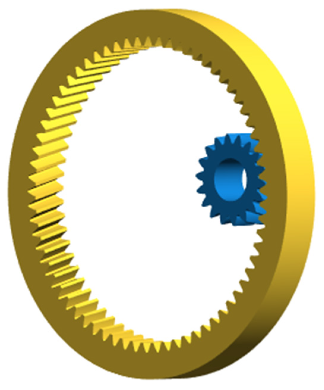
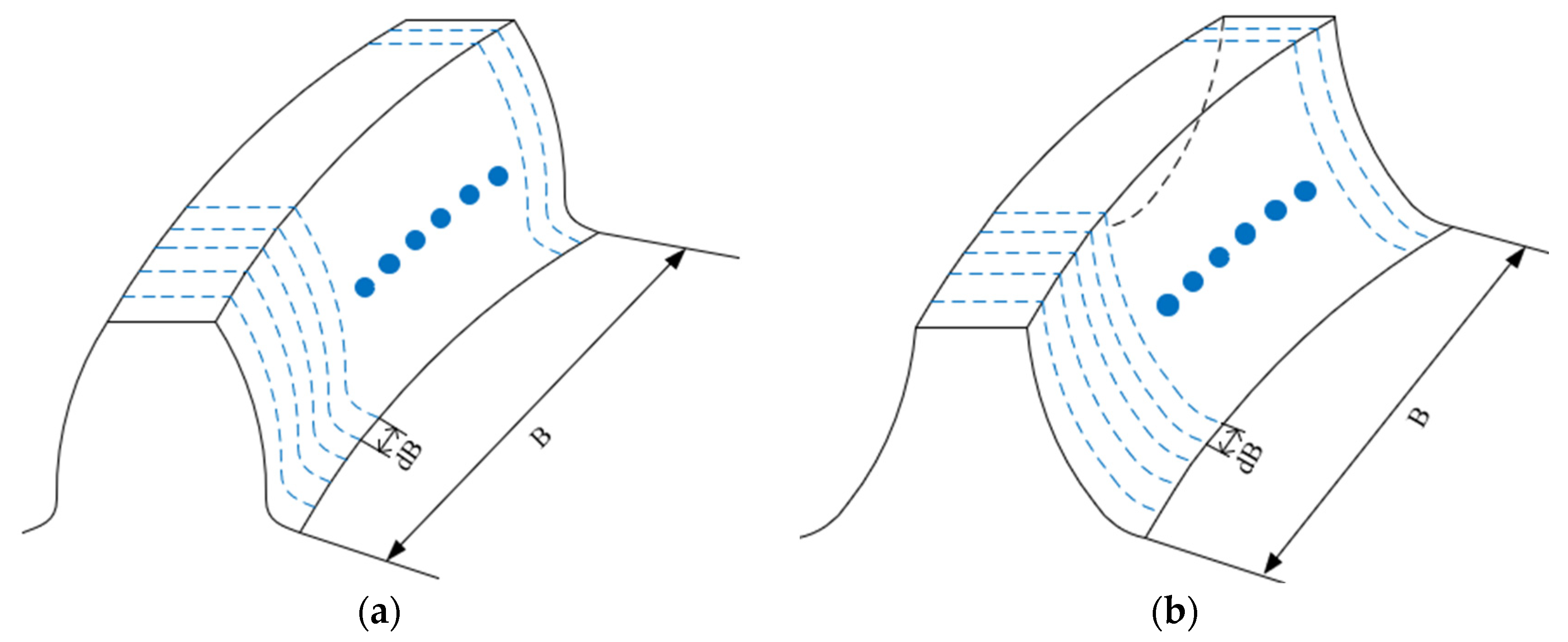
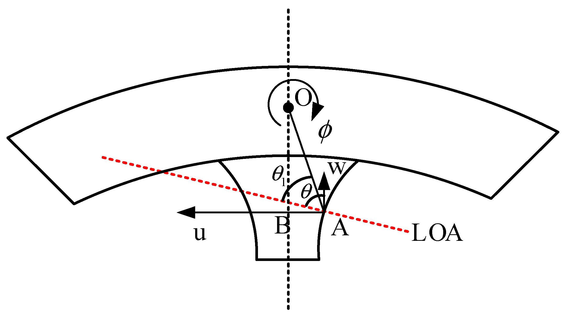
2.1. Establishment of Slice Model for the Internal Gear Pair

Due to the helix angle, there is an angle between the contact line and the axis of the helical gear, and its length changes. Therefore, the calculation of the helical gear mesh stiffness cannot simply be regarded as spur gears. In order to accurately calculate the mesh stiffness of the internal helical gear pair, it was sliced along the face width direction. When the slice thickness was small enough, it could be approximated as a spur gear. The slice diagram of external and internal helical gears is shown in Figure 2. Here, dB is the thickness of the slice element. This can be expressed as:
d B = B / t
where B represents the face width and t denotes the number of slices.

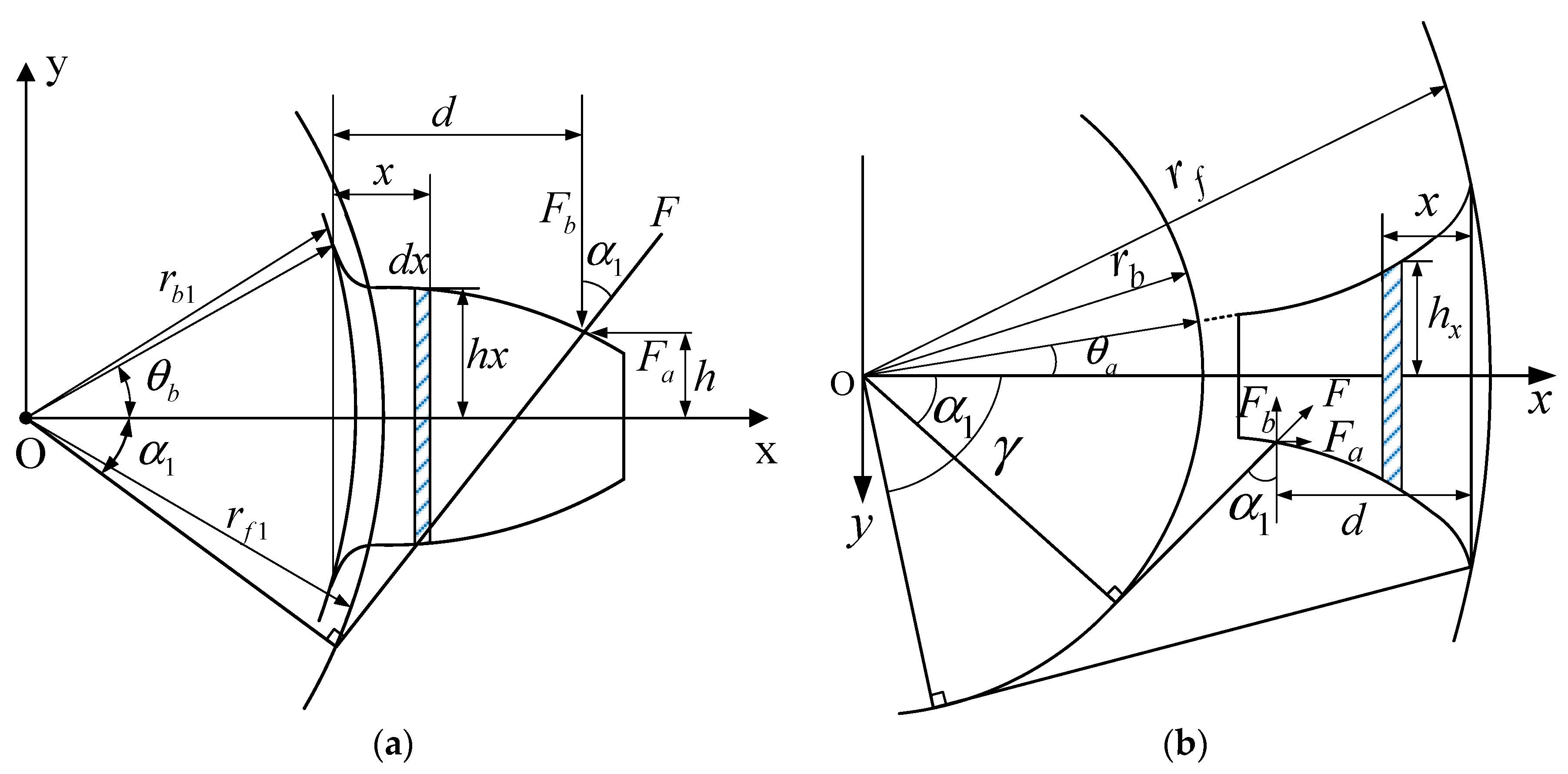
2.2. Calculation of Slice Mesh Stiffness

In this paper, the potential energy method within the analytical method was used, which can be analyzed and calculated according to the actual tooth profile, where the solution speed is fast, and the precision is high. The energy during gear meshing is mainly composed of bending potential energy Ub, shear potential energy Us, compressive potential energy Ua, contact potential energy Uh, and gear foundation potential energies Uf, which correspond to bending stiffness kb, shear stiffness ks, compressive stiffness ka, contact stiffness kh, and gear foundation stiffness kf, respectively.

2.2.1. Tooth Stiffness

The internal and external tooth stiffness includes the bending stiffness, shear stiffness and compressive stiffness. When calculating, the section from the root to the top of the tooth is regarded as a variable cross-section cantilever beam. Due to the differences in the tooth profiles of the internal and external gears, the cantilever beam model needs to be constructed separately. The cantilever beam model of the internal and external gear is shown in Figure 3.
Based on the potential energy method in elasticity, the relationship between the energy stored in the tooth and its stiffness can be expressed as follows:
U b = F 2 2 k b = 0 d M 2 2 E I x d x U s = F 2 2 k s = 0 d 1.2 F b 2 2 G A x d x U a = F 2 2 k a = 0 d F a 2 2 E A x d x
where E denotes the elastic modulus, G represents the shear modulus ( G = E 2 ( 1 + ν ) ), and v is the Poisson’s ratio. The torque M and the mesh force components Fa, Fb can be expressed as:
F b = F cos α 1 F a = F sin α 1 M = F b ( d x ) F a h
where Ix is the moment of inertia at any point and Ax is the cross-sectional area of the microelement. The calculation formula is as follows:
I x = 2 3 h x 3 d B , A x = 2 h x d B
where hx is the half-width of the microelement.
According to the involute tooth profile equation, the parameters d, h, hx, x, dx are expressed as an expression with the mesh angle  α  as the variable. Substituting into Equation (2), the calculation formulae of the bending stiffness, shear stiffness, and compression stiffness of the internal and external gear slice elements can be obtained as follows:
1 k b p ( g ) = α 1 ( γ ) θ b ( α 1 ) 3 ± 1 + cos α 1 ( ± ( θ b ( a ) α ) sin α cos α ) 2 ( θ b ( a ) α ) cos α 2 E d B [ ( θ b ( a ) α ) cos α + sin α ] 3 d α 1 k s p ( g ) = α 1 ( γ ) θ b ( α 1 ) 1.2 ( 1 + v ) ( θ b ( a ) α ) cos α cos 2 α 1 E d B [ ( θ b ( a ) α ) cos α + sin α ] d α 1 k a p ( g ) = α 1 ( γ ) θ b ( α 1 ) ( θ b ( a ) α ) cos α sin 2 α 1 2 E d B [ ( θ b ( a ) α ) cos α + sin α ] d α
where p and g are the external and internal helical gears, respectively. “()” outside and inside are the calculated parameters for the external and internal helical gears, respectively, and “ ± , ”, where the top refers to external helical gears and the bottom refers to internal helical gears. The meanings of the other parameters are shown in Figure 3.
The tooth stiffness expression of the internal and external gear slice elements can be obtained by summing Formula (5). Its independent variable is the mesh angle  α . The calculation formula of gear tooth stiffness at any point on the tooth profile is determined through polynomial fitting:
1 k t p α = p o l y f i t 1 k b p + 1 k s p + 1 k a p 1 k t g α = p o l y f i t 1 k b g + 1 k s g + 1 k a g

2.2.2. Contact Stiffness

The contact stiffness can be obtained by Hertz contact theory. The internal and external gear teeth meshing with each other are regarded as two convex and concave cylinders with Hertzian contact and has little relation to the contact position, load, and shape. The error of mesh stiffness obtained was less than 0.5% [23,24]. Therefore, it can be calculated as a fixed value, and the specific formula is:
k h = π E d B 4 ( 1 v 2 )

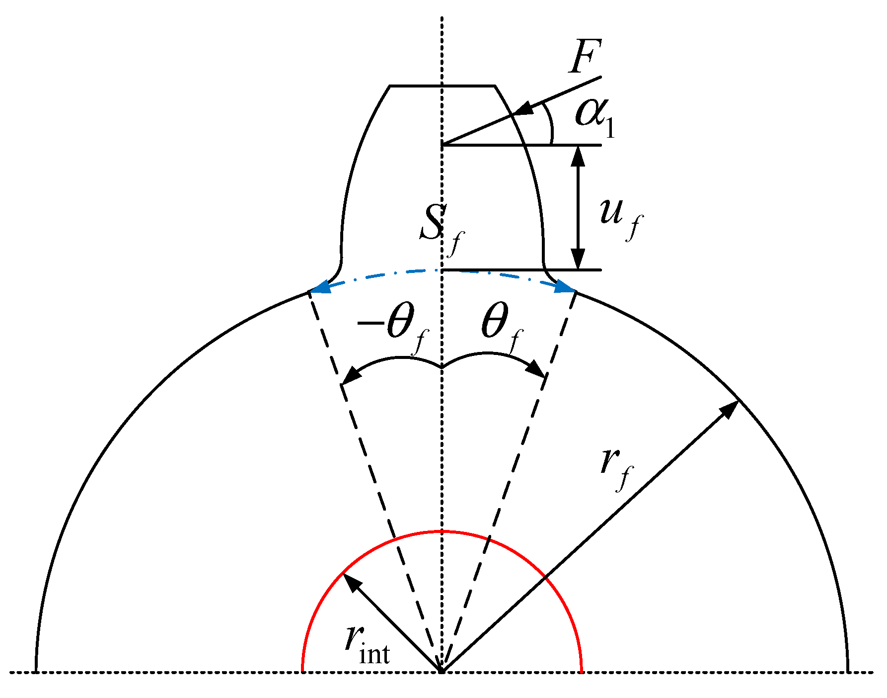
2.2.3. Gear Foundation Stiffness

(1)
Foundation stiffness of the external gear
The mesh stiffness of the gear is not only the cantilever beam part above the tooth root, but also the gear foundation part that will produce stiffness resistance deformation. The external gear is treated as elastic rings, as illustrated in Figure 4. For external gears, the inner and outer diameters of the ring correspond to the shaft hole and the root circle diameter, respectively.
The foundation stiffness is calculated as follows [25]:
1 k f = cos 2 α 1 E d B L * u f S f 2 + M * u f S f + P * 1 + Q * tan 2 α 1
In the formula, the specific calculation formula and the meaning of each parameter can be found in reference [25].
(2)
Foundation stiffness of the internal gear ring
Because the foundation structure of the internal gear ring and the external gear is quite different and Formula (8) has not been successfully applied to the solution of the internal gear ring foundation deformation, this study decided to utilize the Timoshenko beam theory to obtain the deformation of this part. When this theory is applied to the analysis of internal gear ring foundation deformation, the deformation can be categorized into three components: the radial displacement w, circumferential displacement u, and cross-section rotation  ϕ  under the action of force F. The specific calculation principle of this parameter can be found in reference [26]. The deformation of the gear ring foundation is shown in Figure 5:
From Figure 5, it can be observed that the deformation of the gear ring foundation can be expressed as:
δ r i n g = w cos θ + u sin θ + ϕ O A sin θ 1
The specific calculation methods of w, u, and  ϕ  are shown in [26].
Thus, the foundation stiffness of the flexible gear ring can be expressed as:
K f g = F m δ r i n g
According to slice mesh theory [27], the calculation formula of the comprehensive mesh stiffness of any mesh point on the internal mesh gear slice is as follows:
1 k = 1 k h + 1 k t p α + 1 λ 1 k f p + 1 k t g α + 1 λ 2 k f g
where  λ 1 , λ 2  represents the tooth foundation stiffness correction factor of the external gear and the internal gear, respectively [28].

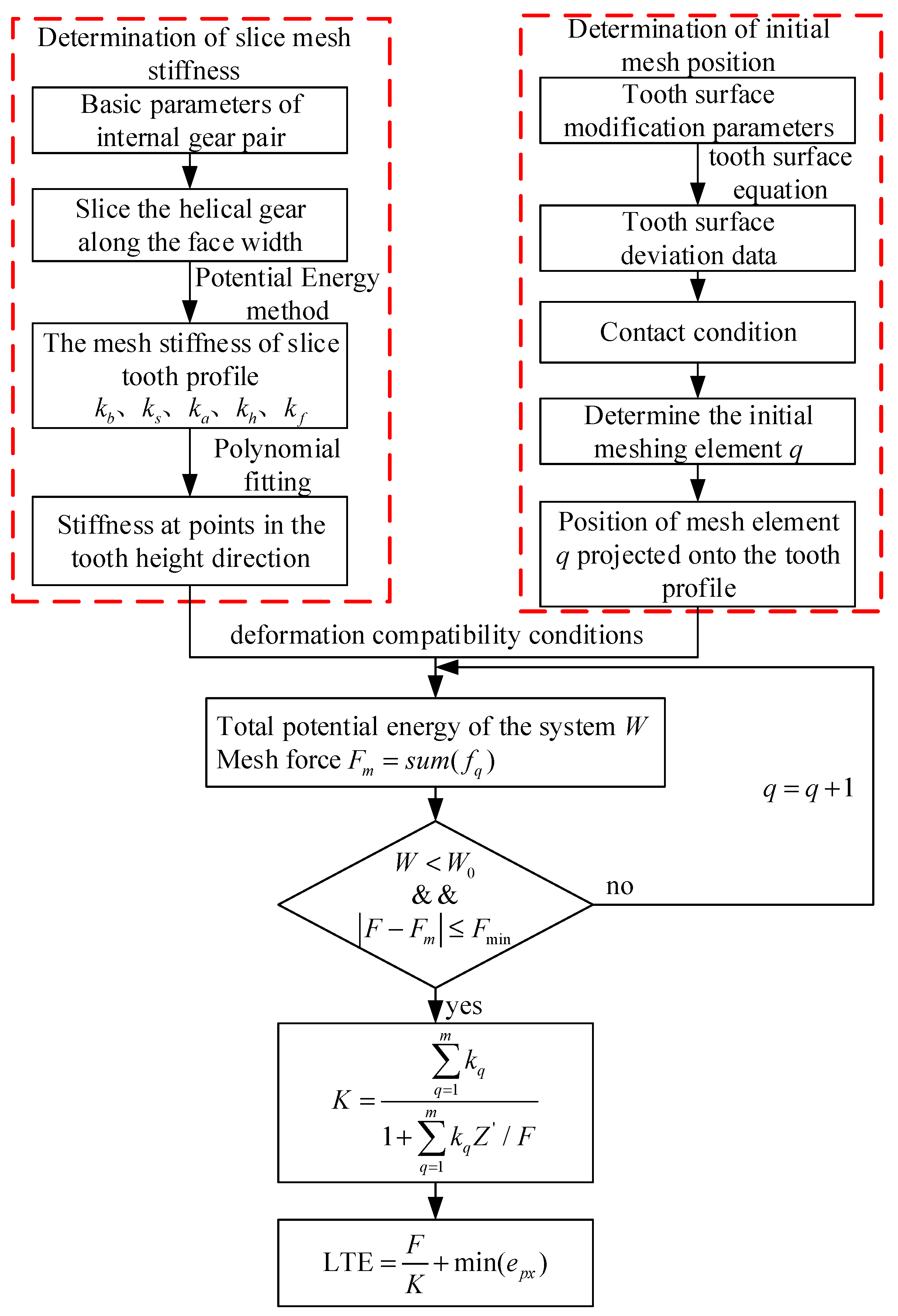
3. TVMS Based on Load Tooth Contact Analysis

In practice, gears must be modified (external gear modification was chosen in this paper) to reduce the mesh shock within the gear system. Due to the deviation of each tooth surface point on the helical gear caused by modification, the contact form is changed from line contact to point contact during meshing. Therefore, the tooth surface deviation, contact deformation, and force balance must be considered when calculating the mesh stiffness, so that the TVMS variation trend of the gear under load can be accurately obtained.

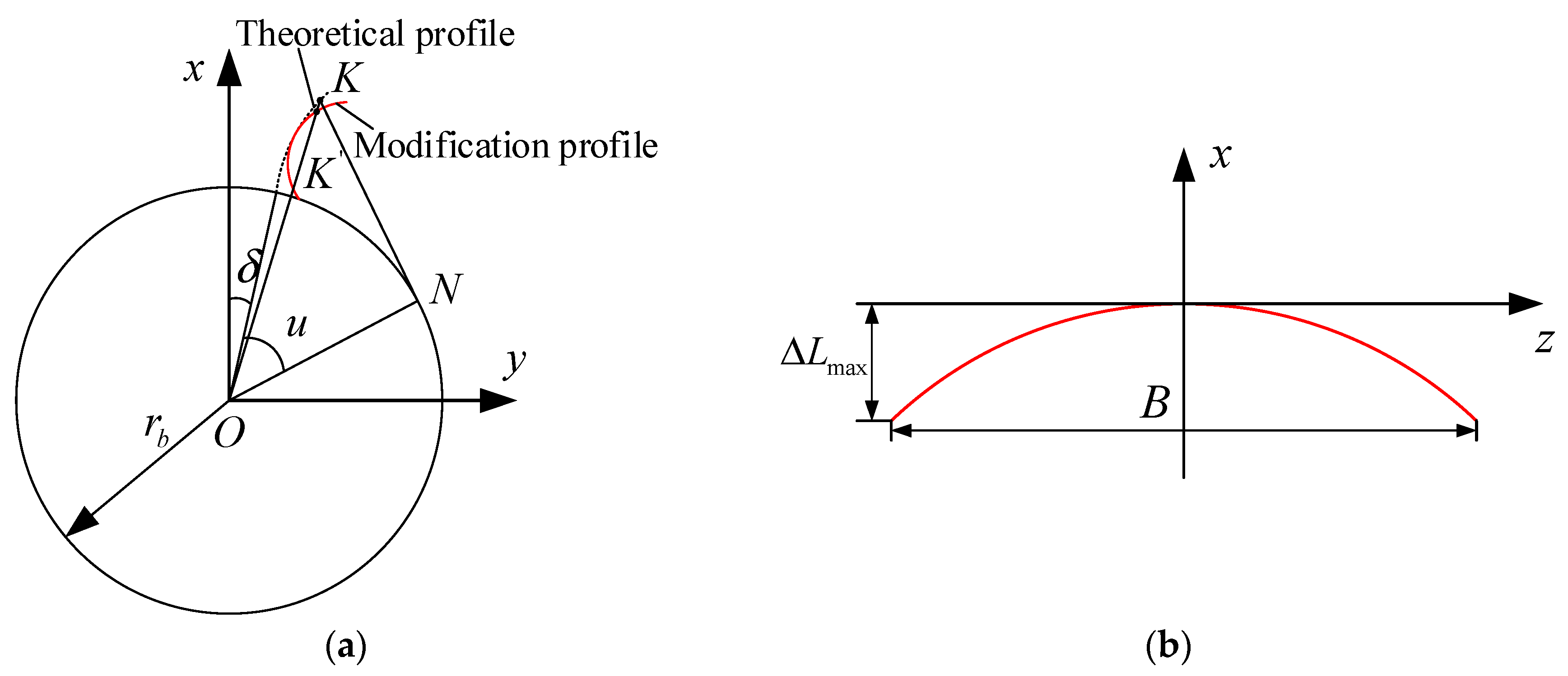
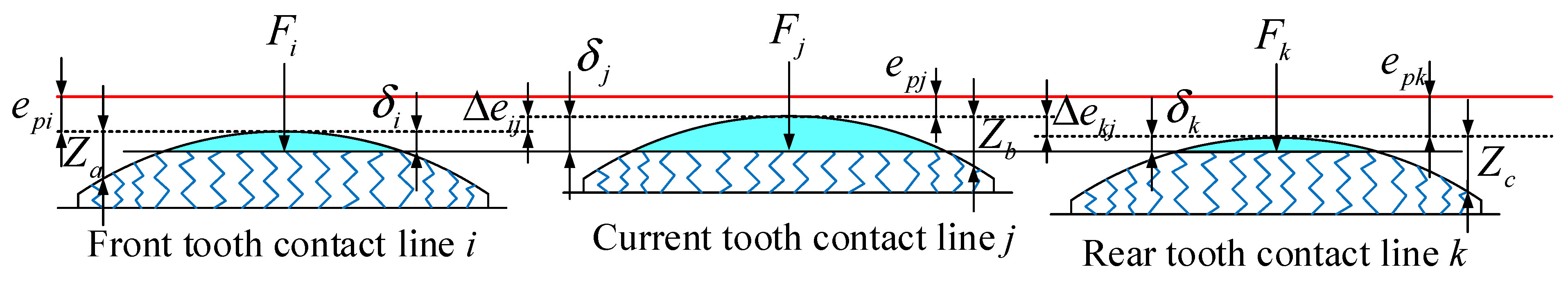
3.1. Calculation of Topological Modification Tooth Surface Deviation

In this paper, the tooth profile and the flank line crowning of the external gear teeth were carried out at the same time, as shown in Figure 6. For the tooth profile modification, the modification amount of each point on the involute is variable, which is expressed by function  Δ C . Flank line crowning uses the most common drum modification (quadratic parabola modification), and its curve function is  Δ L .
Δ C = a 1 L L 0 2 + a 2 L L 0 + a 3 Δ L = b 1 P θ B / 2 2 + b 2 P θ B / 2 + b 3
where a1, a2, a3 is the coefficient of tooth profile modification function, L is the generating line length at  K  of the modified tooth profile, L0 is the generating line length of the point whose modification is 0. b1, b2, b3 is the coefficient of flank line crowning function,  θ  denotes the rotation angle of the  K  point around the z-axis on the modified tooth profile, P is the helix parameter, and the expression is as follows:
P = m n z 2 sin β
After tooth profile modification, any point on the transverse tooth profile can be expressed as follows:
r 1 = r b cos ( δ + u ) + ( r b u + Δ C ) sin ( δ + u ) r b sin ( δ + u ) ( r b u + Δ C ) cos ( δ + u ) 0 1
where  r b  is the radius of the base circle,  δ  is the tooth thickness half-angle of the base circle, and  u  is the rolling angle of any point.
The topological modification tooth surface equation R1 is derived by rotating the modified tooth profile curve around the z-axis.
R 1 = M 1 t r 1 M 1 t = cos θ sin θ 0 Δ L sin θ sin θ cos θ 0 Δ L cos θ 0 0 1 P θ 0 0 0 1
The topological modification tooth surface equation is obtained by the modification curve, and MATLAB R2020a can be used to determine the modification amount at each point on the tooth surface. Finally, the ease-off diagram illustrating the difference between the modified tooth surface and the theoretical tooth surface is obtained, where the difference at each point on the tooth surface is represented by Z, as shown in Figure 7.

3.2. Calculation of Time-Varying Mesh Stiffness

The calculation of the time-varying mesh stiffness of the internal helical gear pair involves both the external and internal gears. The mesh stiffness of the internal mesh slice gear pair was determined using the mesh stiffness calculation method described in Section 2. When the load changes due to tooth surface deviation, the slice elements on the contact line are involved in the contact according to the order of the mesh clearance from small to large. At the same time, the number of elements involved in mesh contact is time-varying. Therefore, it is necessary for the comprehensive mesh stiffness of the internal helical gear pair to be determined through load tooth contact analysis.
Figure 8 illustrates the mesh clearance of the sliced tooth pairs on the contact line when the tooth surface deviation exists under the load state. The red solid line and the black dotted line represent the theoretical and actual contact positions, respectively.  e p x  and  e g x  represent the tooth surface deviations of the external gear and the internal gear, respectively (x is the sliced tooth pair on the contact lines i, j, k. Only the external gear was modified, so  e g x = 0 ).  δ i , δ j , δ k  are the deformations of the contact lines i, j, k under load.
When three pairs of teeth are in contact, the sliced tooth pairs i, j, k at the ridge point of the contact line between the front tooth, current tooth, and rear tooth move distances  e p i , e p j , e p k , respectively, under the load F. This means that the point with the smallest tooth surface deviation on each contact line makes contact first. The geometric relationship between the tooth pair deformation and the tooth surface deviation is as follows:
δ i + e p i = δ j + e p j δ j + e p j = δ k + e p k
As shown in Figure 8, the tooth surface deviation at the ridge point of the current tooth contact line is the smallest, so the contact occurs first when the three teeth mesh. The relative values of the tooth surface deviation at the contact line ridge points of the front and rear teeth relative to the tooth surface deviation at the contact line ridge point of the current tooth are  Δ e i j , Δ e k j . Therefore, for contact to occur between the slice element pair at the contact line ridge point between the front tooth and the rear tooth, the relative value of the tooth surface deviation must be overcome. According to Equation (16), the relative value of the tooth surface deviation can be determined as follows:
Δ e i j = δ j δ i = e p i e p j Δ e k j = δ j δ k = e p k e p j
Slice tooth pairs i, j, and k represent the element pairs located at the ridge point on the contact line of the current, front, and rear teeth, respectively. In a three-tooth mesh, the mesh clearance between the front and rear teeth is influenced by the relative value of the tooth surface deviation. Therefore, it is essential to consider the relative value of the tooth surface deviation of the element pair along the contact line between the current tooth and the adjacent front and rear teeth. However, the mesh clearance of the current tooth is equal to the tooth surface clearance. Therefore, the mesh clearance of any slice element pair on the contact line of the front tooth, the current tooth, and the rear tooth can be expressed as follows:
Z a = Z a + Δ e i j Z b = Z b Z c = Z c + Δ e k j
where  Z a , Z b , Z c  denote the tooth surface clearance of the slice element on the contact line of the front tooth, the current tooth, and the rear tooth, respectively.
When three teeth are in contact, the mesh order of all element pairs on the three contact lines is that contact occurs first when the mesh clearance is minimal. The mesh clearances of all elements on the three contact lines are placed in a matrix and sorted from smallest to largest to determine the order of contact between the element pairs.
Z = s o r t [ Z a , Z b , Z c ]
where  Z a , Z b , Z c  is the meshing clearance of the element pairs on the contact line of the front tooth, the current tooth, and the rear tooth, respectively.  Z  is the mesh clearance of any mesh element pair, and sort is a sort function from small to large.
The load F is equal to the sum of the mesh forces  f q  of each slice mesh element that satisfies the contact condition, which can be expressed as:
F = q = 1 m f q
where m is the number of slice element pairs that mesh at the same time.
According to Hooke’s law, there are the following relationships among the mesh force  f q , deformation  δ q , and mesh stiffness  k q  of the slice element in the mesh state.
f q = k q δ q
δ q = δ j Z , where  δ j  is the deformation of mesh element pair j at the ridge point (max deformation). When  δ q > 0 , the mesh element pairs are in contact.
Through the contact condition and the force equilibrium condition, the deformation compatibility equation can be derived as follows:
F = q = 1 m f q = q = 1 m k q ( δ j Z )
In the load state, it is known from the principle of minimum potential energy that the gear system will achieve equilibrium only when the energy stored in the mesh elements is minimized. The expression for minimum potential energy is as follows:
W = q = 1 m f q ( δ j Z ) = q = 1 m k q ( δ j Z ) 2
Therefore, the TVMS of the three-tooth mesh can be calculated as follows:
K = F max ( δ i , δ j , δ k )
By combining Equations (20)–(24), the expression for the TVMS of the internal helical gear pair can be derived.
K = q = 1 m k q 1 + q = 1 m k q Z / F
In the load state, the calculation formula of LTE is:
LTE = F K + min ( e p x )
The TVMS calculation flow of the internal mesh transmission based on load tooth contact analysis can be found in Figure 9. It can be observed from Figure 9 that the flow can be divided into three parts. The first step is to calculate the mesh stiffness of the slice gear pair at different positions on the tooth profile. The mesh stiffness expression with the mesh angle as the independent variable is obtained by fitting. Then, prepare for the subsequent TVMS calculation. The second step is to determine the initial mesh position under the load state. According to the parameters for tooth surface modification and the tooth surface equation, the tooth surface deviation data are obtained. The relative position relationship of the slice element pairs on different contact lines during three-tooth meshing is established to determine the meshing gap of these pairs. The mesh sequence of the slice element pair is determined based on the mesh clearance. The mesh stiffness of this element pair is determined based on its position on the tooth profile. The third step is to determine the number of slice element pairs involved in meshing, according to the deformation coordination principle and the minimum potential energy method, so as to determine the mesh stiffness corresponding to the rotation angle.

4. Numerical Simulation Results and Validation

The gear pair parameters applied in this paper are presented in Table 1, and were derived from the planetary reducer for mining machinery mills. Through the method proposed in this paper, the optimal modification amount and appropriate working load of the internal helical gear pair could be determined to effectively reduce the vibration impact of gear mesh.

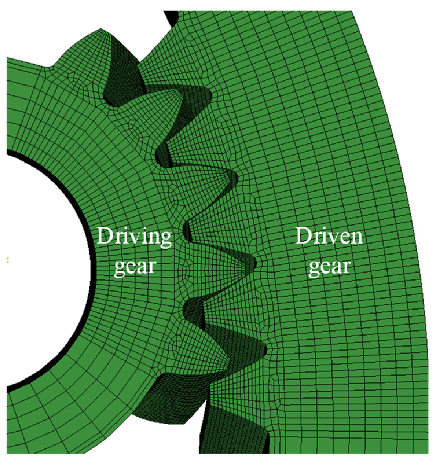
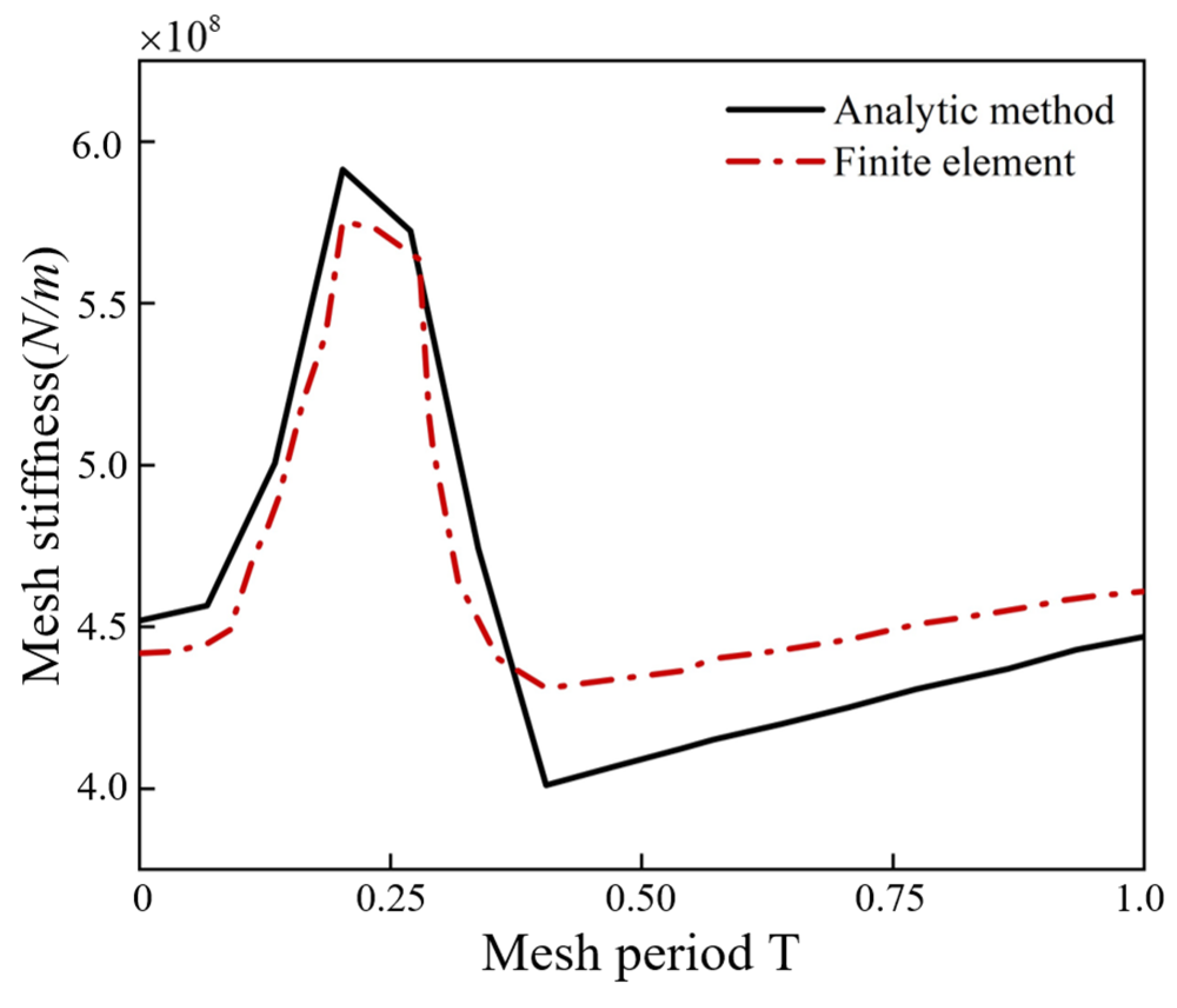
4.1. Validation of Finite Element Results

The finite element simulation can accurately determine the TVMS of gears, which was fully verified during the study [29,30]. In order to verify the correctness of the proposed method, finite element simulation of the internal gear pair was conducted using Abaqus 2022. Modeling based on the internal gear pair parameters is provided in Table 1. In order to expedite the solution, five pairs of teeth were selected for simulation. The corresponding simulation model is shown in Figure 10. Before the simulation, the following tasks must be completed. First, the model should be divided into grids of different sizes based on their significance to the simulation results. The grid type is hexahedral, as shown in Figure 10. The grid sizes of the gear teeth, the gear foundation connected to the retained gear teeth, and the remaining hub section were as follows: 0.8 × 0.8 × 0.8   mm ,   2 × 1 × 1   mm ,   4 × 2 × 1   mm . The number of elements in the driving gear and the driven gear were 83,148 and 153,374, respectively. Second, the elastic modulus and density were determined based on the material properties of the model. Third, the interaction setting: the contact type was ‘hard contact’, and the friction coefficient was 0.1. The primary and secondary surfaces were the tooth surfaces of the driving gear and the driven gear, respectively. Fourth, to facilitate the application of boundary conditions, the nodes of the driving and driven gear shaft holes were coupled with their corresponding central nodes. Finally, the axial rotational freedom of the driven wheel was released, and the rotational speed and load were applied to the driving and driven gears, respectively. The simulation model was solved to obtain the desired results. The expression for TVMS is as follows:
K = T Δ θ r b 2
where T is the gear load torque,  Δ θ  represents the angular displacement difference, and rb is the base radius.
Δ θ = θ 2 θ 2
where  θ 2  and  θ 2  represent the actual and theoretical rotation angles of the driven gear, respectively.
In this paper, the change of mesh stiffness when the gear load torque was 600 N·m was verified by finite element simulation, as shown in Figure 11. The results indicate that within a mesh cycle, the proportions of the three-tooth and two-tooth mesh areas were basically the same, and the trend in mesh stiffness changes was generally consistent. The results were similar in the three-tooth mesh area, and the maximum error was only 2.78%. However, the finite element results for the two-tooth contact area were slightly larger than the calculated results presented in this paper. The maximum error was approximately 7.48%, and the minimum error was around 3.13%. The average value error was about 4% in the entire mesh cycle. It is evident that the overall change trend and the average value error were within the acceptable range. Therefore, the effectiveness of the proposed method was demonstrated through finite element simulation.

4.2. The Influence of Different Factors on TVMS and LTE

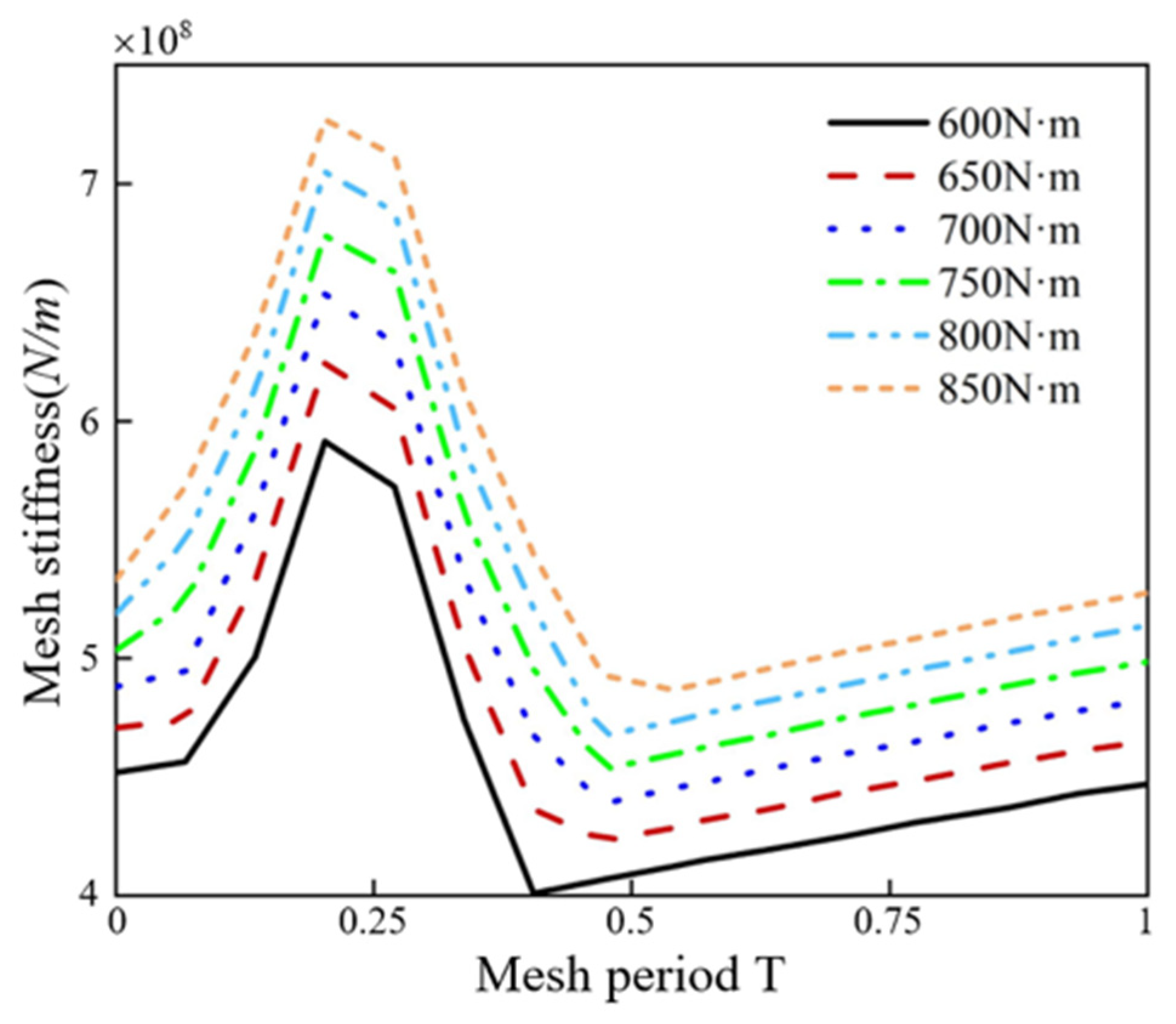
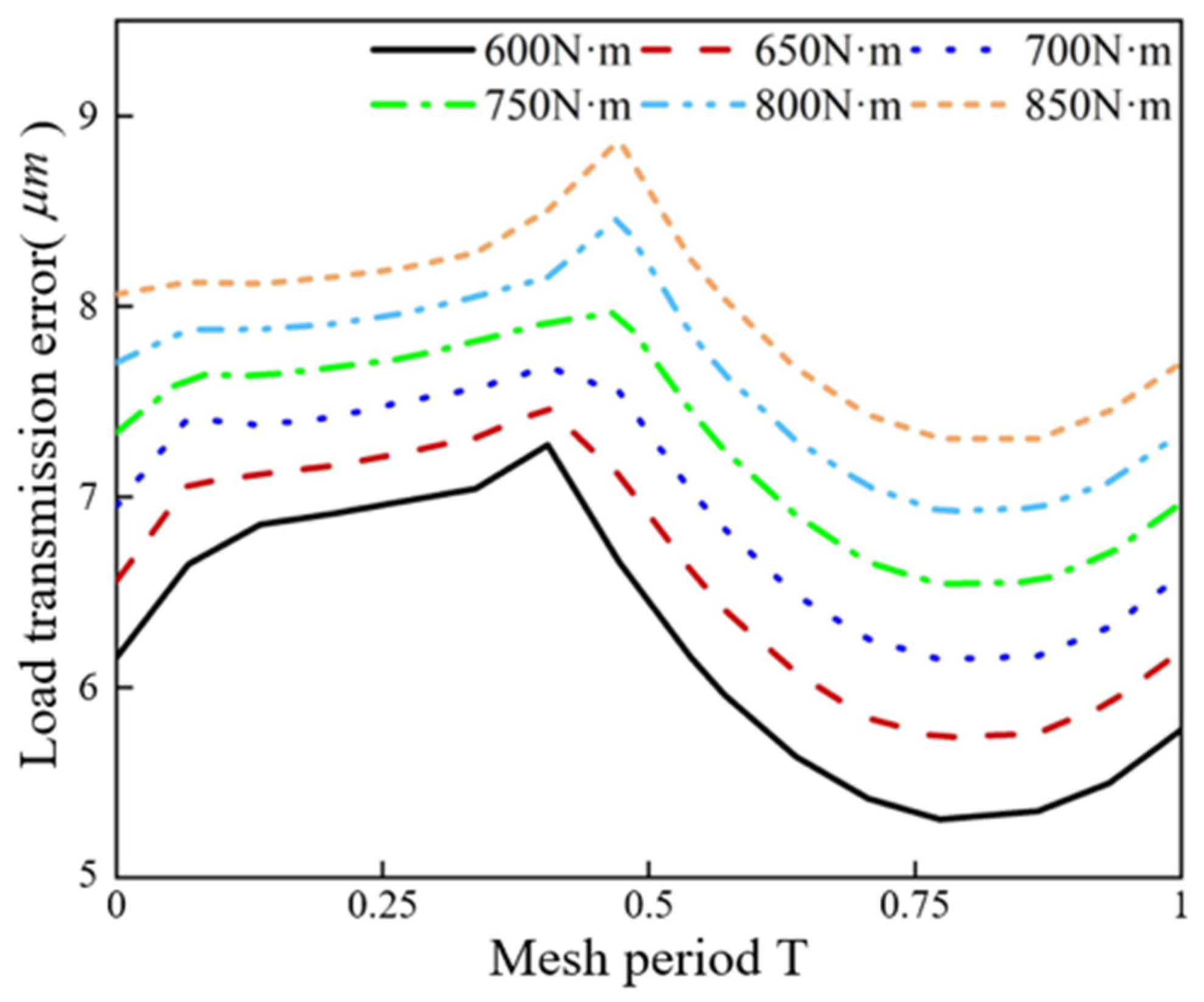
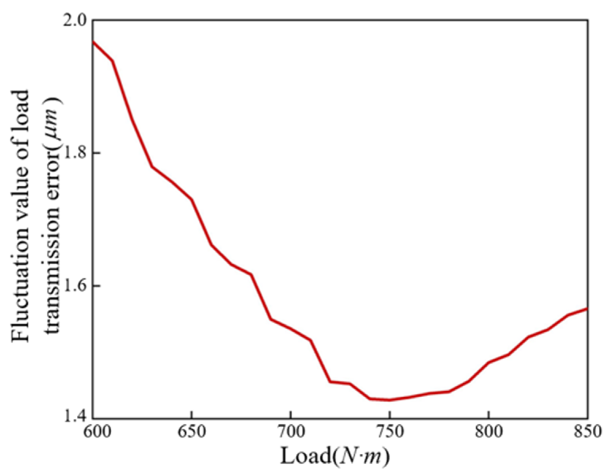
4.2.1. The Influence of Load on TVMS and LTE

For this set of gear parameters, a working load range of 600 N·m to 850 N·m was selected in this paper to study the effect of load on the TVMS and LTE. The influence of load on the TVMS and LTE of the modified internal helical gear is shown in Figure 12 and Figure 13. As the load gradually increased from 600 N·m to 850 N·m, both the TVMS and LTE continued to rise. At the same time, it was evident that the two-tooth mesh area decreased and the three-tooth mesh area increased. The increase in TVMS can enhance the ability of gears to resist deformation. However, the increase in transmission error may result in a more serious mesh impact. In order to determine the appropriate load, a load range can be determined based on the fluctuation degree of the transmission error, thereby minimizing the impact on the gear mesh.
In order to clarify the influence of load on the amplitude fluctuation of LTE, the load was increased from 600 N·m, with an interval of 10 N·m, to 850 N·m. The fluctuation amplitude curve is shown in Figure 14. The LTE fluctuation value reached its minimum value when the load was 750 N·m, after which it began to increase gradually. It can be concluded that although the TVMS increases with the increase in load, the stability of the system can be improved. However, the fluctuation of LTE is not conducive to reducing vibration noise. Therefore, in engineering practice, the appropriate working load range needs to be determined on the premise that the LTE fluctuation is small.

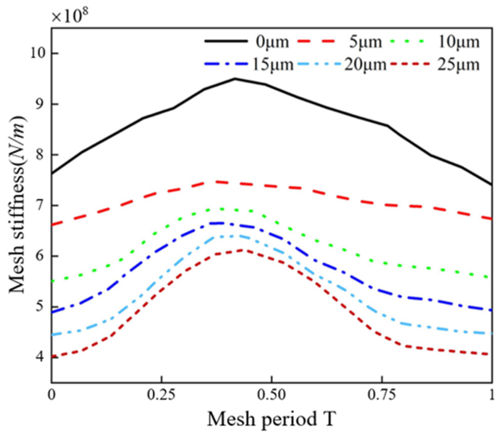
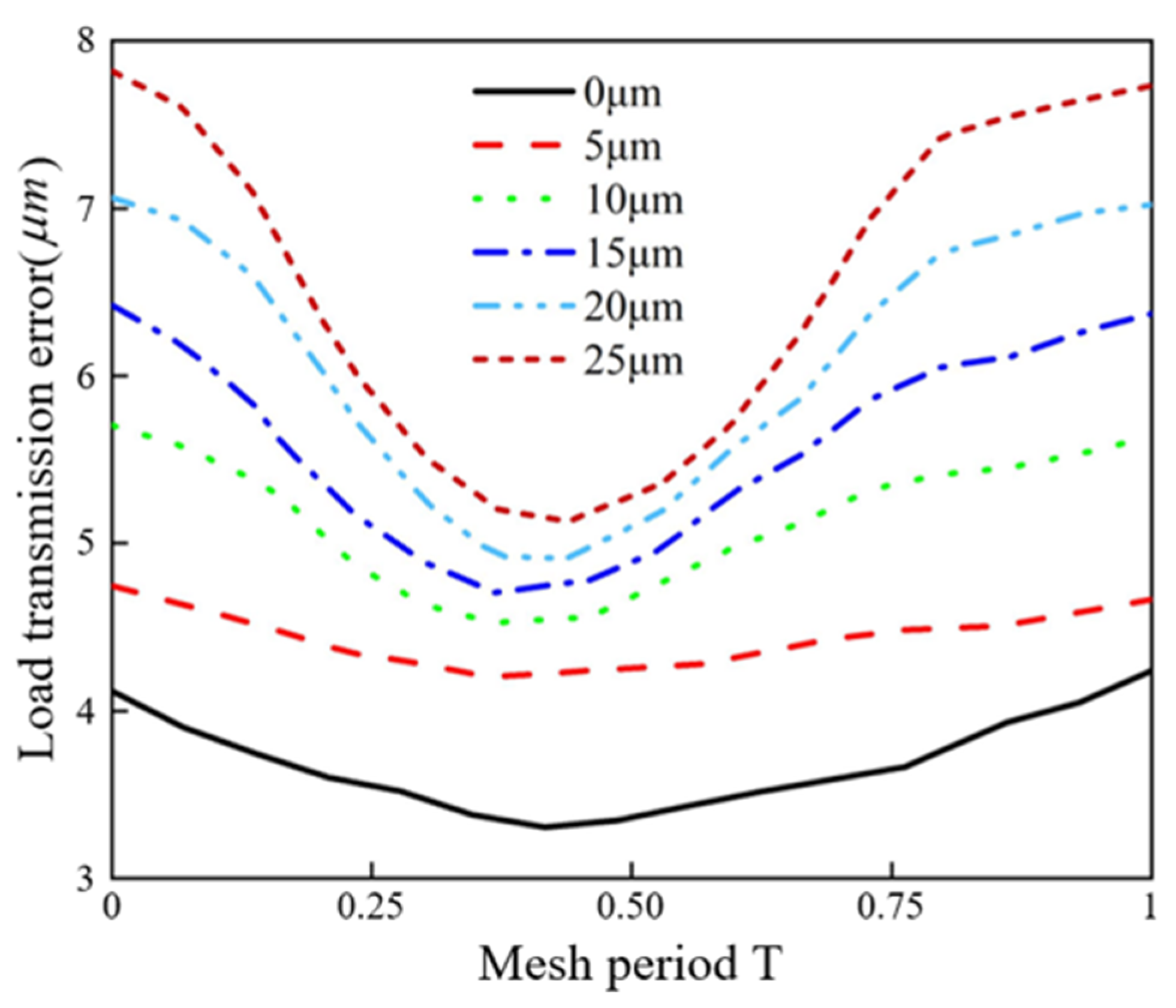
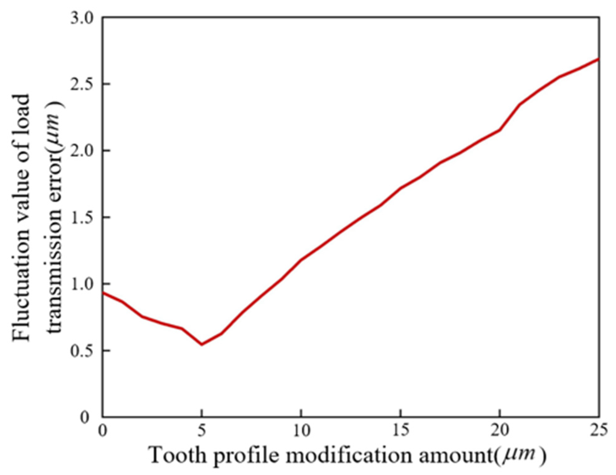
4.2.2. The Influence of Modification Amount on TVMS and LTE

In order to study the influence of tooth profile modification on the TVMS and LTE of internal helical gears,  Δ C max  was increased from 0 μm to 25 μm, with 5 μm as the interval. As shown in Figure 15 and Figure 16, the TVMS gradually decreased with the increase in modification amount, but the LTE increased, demonstrating an inverse tendency between the two.
Figure 17 illustrates the variation trend in the LTE fluctuation value with the modification amount. It can be clearly seen that the amplitude fluctuation of LTE reached its minimum value when the tooth profile modification amount was 5 μm. Therefore, it can be known that the appropriate modification effectively reduces the LTE fluctuation value and mitigates the vibration impact during meshing. However, excessive modification can lead to a decline in the TVMS and an increase in the LTE fluctuation values. Thus, a balanced consideration should be given when selecting the modification amount.

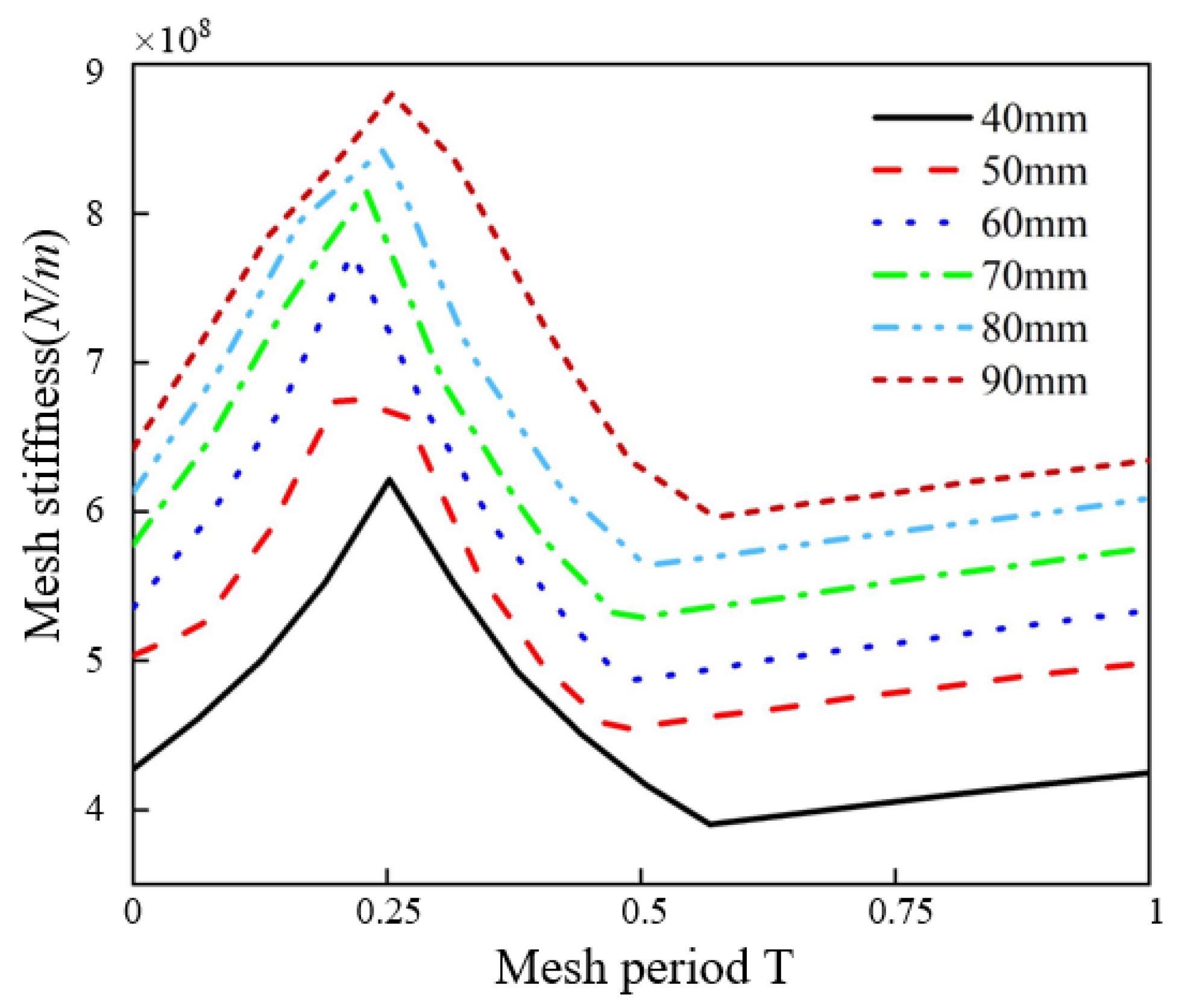
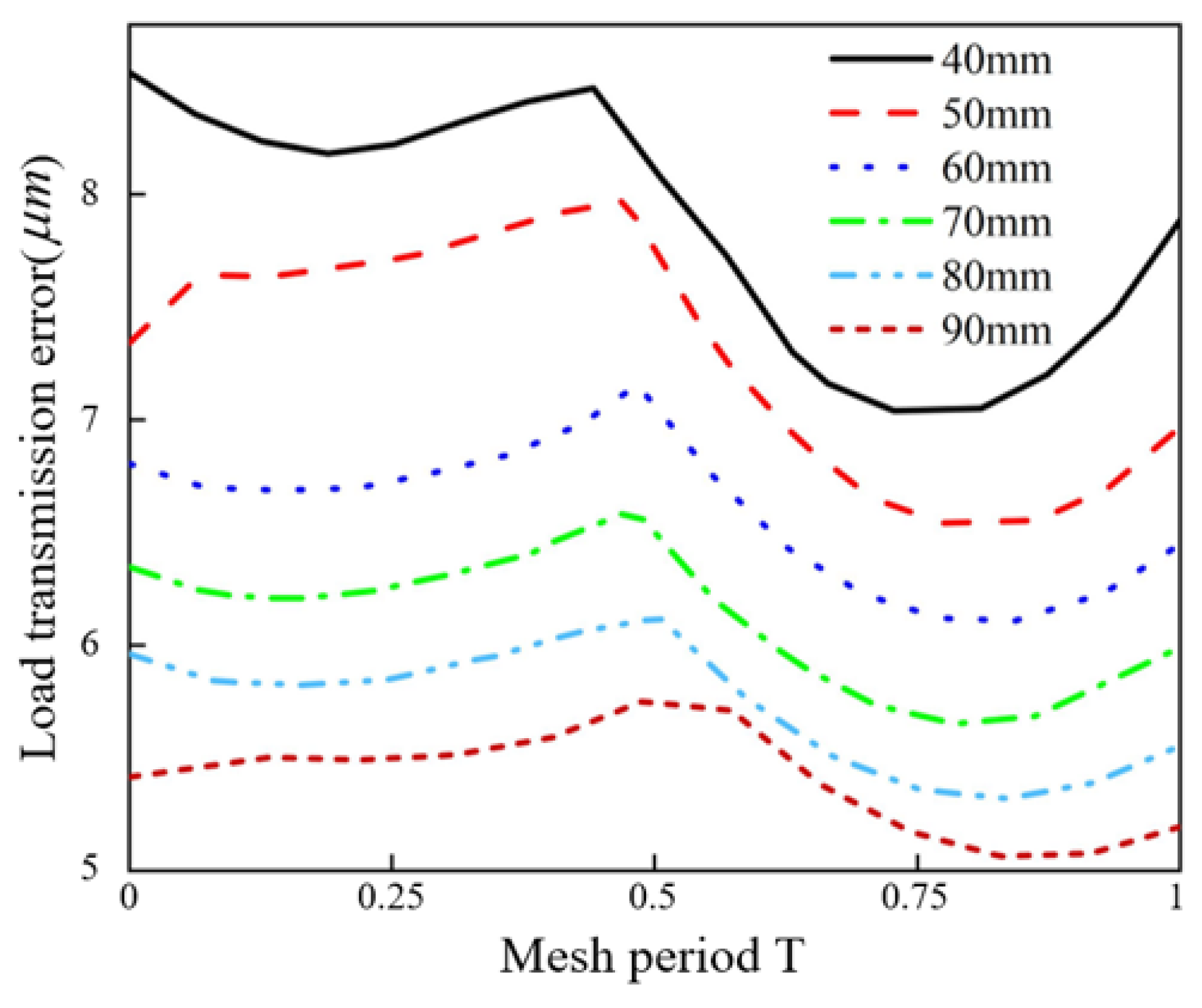
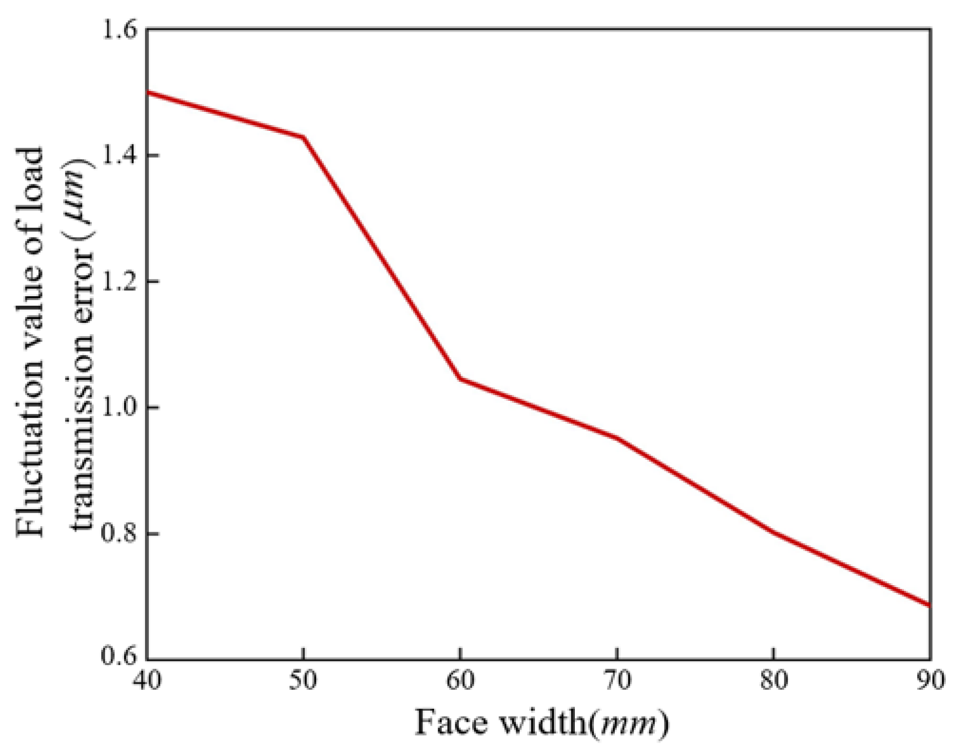
4.2.3. The Influence of Face Width on TVMS and LTE

The influence of face width on the TVMS and LTE of internal helical gears was also studied. While the other parameters remained constant, the face width was increased from 40 mm to 90 mm in increments of 10 mm. The result change curve is illustrated in Figure 18 and Figure 19. When the face width increased, the axial contact ratio also increased, and the ability of the gear teeth to resist deformation was enhanced. As a result, the deformation decreased, and the mesh stiffness increased. On the other hand, the LTE decreased as the face width increased.
Figure 20 shows the variation trend in the LTE fluctuation value with face width. It can be clearly seen that a larger the face width, the smaller the fluctuation value. The variation trend in the LTE fluctuation value shows that the face width can effectively enhance the stability of the system.

5. Discussion

In this paper, the slicing method and the potential energy method were applied to analyze the load performance of internal helical gears. This approach aimed to fill the gap of the analytical method in determining the mesh stiffness and load transmission error. The gear teeth were sliced by slicing method, and the external and internal gears were analyzed by the potential energy method. The unified calculation formula of gear tooth stiffness was obtained. Based on this, calculations of the TVMS and LTE for multi-tooth mesh was carried out. The dynamic mesh stiffness and LTE of the internal helical gear were obtained under load conditions as the optimal load and modification amount for the internal helical gear pair can be quickly determined by this method. This establishes a foundation for further design, manufacturing, and dynamic analysis of the internal helical gear pair.
The energy method was used to calculate the load transmission error, which makes up for the time-consuming disadvantage of the finite element method. At the same time, the optimal modification amount under working load can be quickly obtained, so that the fluctuation amplitude of the load transmission error is minimized, and the vibration and noise of the transmission system are reduced. This provides a basis for the modification design and manufacture of the gear.
Next, the authors will apply this analytical model to planetary gear systems, aiming to further enhance the practicality and reliability of the analytical model. In addition, we will also consider the impact of installation and manufacturing errors.

6. Conclusions

In this paper, an analytical model for the mesh stiffness of internal mesh transmission was proposed under the loaded state, which considered the effects of gear ring flexibility and tooth surface modifications. In the case of a multi-tooth mesh, the model could accurately account for the sequential mesh order of the slice elements to calculate the TVMS of the tooth surface nonlinear contact. Comparing the improved model with the finite element simulation, the results indicate that the trend of change was consistent, and the maximum error in mesh stiffness was only 7.48%, which proves the correctness of the method presented in this paper.
The effects of load, modification, and face width on the TVMS and LTE of internal mesh transmissions were discussed in detail. The TVMS and LTE both increased with the load increase. However, the fluctuation value of LTE reached its minimum when the load was 750 N·m. When the load was 750 N·m, with an increase of the modification amount, the TVMS decreased and LTE increased. The fluctuation value of LTE reached its minimum value when the tooth profile modification amount was 5 μm. Therefore, minimizing transmission error fluctuations can be used as a design criterion to determine the optimal load range and modification amount during gear optimization design. Meanwhile, the increase in face width not only improved the TVMS and reduced the LTE, but also decreased the fluctuation value of the LTE.
The influence of load, modification, and face width on the TVMS and LTE of an internal helical gear system was studied by the analytical model in this paper. This model not only serves as a reference for the design and manufacture of internal helical gears with low vibration and noise, but also provides a data source for dynamic analysis.

Author Contributions

Conceptualization, J.L. and J.Y.; Methodology, H.Z. and Y.R.; Software, Y.R.; Validation, Y.R. Investigation, H.Z.; Resources, J.L.; Data curation, Y.R.; Writing—original draft preparation, H.Z.; Writing—review and editing, J.L. and J.Y.; Project administration, J.Y.; Funding acquisition, J.Y. All authors have read and agreed to the published version of the manuscript.

Funding

This research was funded by the National Natural Science Foundation of China (No. 52275054), the Key Research and Development Projects in Henan Province (No. 241111221200), the Key Scientific and Technological Project of Henan Province (No. 242102221008), and the Major Science and Technology Project of Henan Province (No. 241100220300).

Institutional Review Board Statement

Not applicable.

Informed Consent Statement

Not applicable.

Data Availability Statement

Data are contained within the article.

Conflicts of Interest

The authors declare no conflicts of interest.

Abbreviations

The following abbreviations are used in this manuscript:
TVMSTime-varying mesh stiffness
LTELoad transmission error
Nomenclature
BFace width
dBSlice element thickness
tNumber of slices
U i i = b , s , a , h , f Bending, shear, compressive, contact, and gear foundation potential energies
k i i = b , s , a , h , f Bending, shear, compressive, contact, and gear foundation stiffness
FMesh force
EElastic modulus
GShear modulus
vPoisson’s ratio
MTorque
I x Moment of inertia
A x Cross-sectional area of the microelement
F i i = a , b Mesh force component
α Mesh angle
dEffective energy storage length
hDistance between mesh point and tooth midline
h x Half tooth thickness corresponding to microelements
wRadial displacement
uCircumferential displacement
ϕ Cross-section rotation
λ i i = 1 , 2 Tooth foundation stiffness correction factor, subscript i denotes the internal gear and external gear
Δ C Tooth profile modification function
Δ L Flank line crowning function
a i i = 1 , 2 , 3 Coefficients of tooth profile modification function
b i i = 1 , 2 , 3 Coefficients of flank line crowning function
L The generating line length at  K  of the modified tooth profile
P Helix parameter
m n Normal module
β Helix angle
θ Rotation angle of the  K  point around the z-axis on the modified tooth profile.
Z Tooth number of modified gear
u Rolling angle
δ Tooth thickness half-angle of base circle
r b Base circle radius of modified gear
δ x x = i , j , k Deformation of slice tooth pairs on the contact line, the subscript x represents the contact line on the front tooth, the current tooth, and the rear tooth
e p x x = i , j , k Tooth surface deviations, subscript x represents the contact line on the front tooth, the current tooth, and the rear tooth
Δ e x j x = i , k Relative values of tooth surface deviation at the contact line ridge points, subscript x indicates the front and rear teeth relative to the current tooth j
Z x x = a , b , c Tooth surface clearance of the slice element on the contact line, subscript x represents the front tooth, the current tooth, and the rear tooth
Z x x = a , b , c Mesh clearance, subscript x represents the front tooth, the current tooth, and the rear tooth
Z Mesh clearance arrangement matrix
f q Mesh force of slice element pair
δ q Deformation of slice element pair
WPotential energy
KTime-varying mesh stiffness
TTorque
Δ θ Angle difference
θ 2 Theoretical rotation angle of the driven gear
θ 2 Actual rotation angle of the driven gear

References

  1. Chang, L.H.; Liu, G.; Wu, L.Y. A robust model for determining the mesh stiffness of cylindrical gears. Mech. Mach. Theory 2014, 87, 93–114. [Google Scholar] [CrossRef]
  2. Rezaei, M.; Poursina, M.; Jazi, S.H.; Aboutalebi, F.H. Calculation of time dependent mesh stiffness of helical planetary gear system using analytical approach. J. Mech. Sci. Technol. 2018, 32, 3537–3545. [Google Scholar] [CrossRef]
  3. Wang, Q.B.; Chen, K.K.; Zhao, B.; Ma, H.; Kong, X.G. An analytical-finite-element method for calculating mesh stiffness of spur gear pairs with complicated foundation and crack. Eng. Fail. Anal. 2018, 94, 339–353. [Google Scholar] [CrossRef]
  4. Raghuwanshi, N.K.; Parey, A. Mesh stiffness measurement of cracked spur gear by photoelasticity technique. Measurement 2015, 73, 439–452. [Google Scholar] [CrossRef]
  5. Raghuwanshi, N.K.; Parey, A. Experimental measurement of gear mesh stiffness of cracked spur gear by strain gauge technique. Measurement 2016, 86, 266–275. [Google Scholar] [CrossRef]
  6. Benatar, M.; Handschuh, M.; Kahraman, A.; Talbot, D. Static and dynamic transmission error measurements of helical gear pairs with various tooth modifications. J. Mech. Des. 2019, 141, 103301. [Google Scholar] [CrossRef]
  7. Wan, Z.G.; Cao, H.R.; Zi, Y.Y.; He, W.P.; Chen, Y.M. Mesh stiffness calculation using an accumulated integral potential energy method and dynamic analysis of helical gears. Mech. Mach. Theory 2015, 92, 447–463. [Google Scholar] [CrossRef]
  8. Yu, W.; Mechefske, C.K. A new model for the single mesh stiffness calculation of helical gears using the slicing principle. Iran J. Sci. Technol.-Trans. Mech. Eng. 2019, 43, 503–515. [Google Scholar] [CrossRef]
  9. Huang, W.K.; Ma, H.; Zhao, Z.F.; Wang, P.F.; Peng, Z.K.; Zhang, X.X.; Zhao, S.T. An iterative model for mesh stiffness of spur gears considering slice coupling under elastohydrodynamic lubrication. J. Cent. South Univ. 2023, 30, 3414–3434. [Google Scholar] [CrossRef]
  10. Chen, K.K.; Huangfu, Y.F.; Ma, H.; Xu, Z.T.; Li, X.; Wen, B.C. Calculation of mesh stiffness of spur gears considering complex foundation types and crack propagation paths. Mech. Syst. Signal Proc. 2019, 130, 273–292. [Google Scholar] [CrossRef]
  11. Liu, Z.; Wang, H.W.; Lu, F.X.; Wang, C.; Zhang, J.C.; Qin, M.J. A New Fast Calculating Method for Meshing Stiffness of Faulty Gears Based on Loaded Tooth Contact Analysis. Processes 2023, 11, 2003. [Google Scholar] [CrossRef]
  12. Chen, Z.G.; Shao, Y.M. Mesh stiffness calculation of a spur gear pair with tooth profile modification and tooth root crack. Mech. Mach. Theory 2013, 62, 63–74. [Google Scholar] [CrossRef]
  13. Autiero, M.; Paoli, G.; Cirelli, M.; Valentini, P.P. The effect of different profile modifications on the static and dynamic transmission error of spur gears. Mech. Mach. Theory 2024, 201, 105752. [Google Scholar] [CrossRef]
  14. Sánchez, M.B.; Pleguezuelos, M.; Pedrero, J.I. Influence of profile modifications on meshing stiffness, load sharing, and trasnsmission error of involute spur gears. Mech. Mach. Theory 2019, 139, 506–525. [Google Scholar] [CrossRef]
  15. Hu, Z.H.; Tang, J.Y.; Zhong, J.; Chen, S.Y.; Yan, H.Y. Effects of tooth profile modification on dynamic responses of a high speed gear-rotor-bearing system. Mech. Syst. Signal Proc. 2016, 76, 294–318. [Google Scholar] [CrossRef]
  16. Chen, Z.Y.; Ji, P.F. Research on the variation of mesh stiffness and transmission error for spur gear with tooth profile modification and wear fault. Eng. Fail. Anal. 2021, 122, 105184. [Google Scholar] [CrossRef]
  17. Sun, Z.; Chen, S.Y.; Hu, Z.H.; Tao, X. Improved mesh stiffness calculation model of comprehensive modification gears considering actual manufacturing. Mech. Mach. Theory 2022, 167, 104470. [Google Scholar] [CrossRef]
  18. Dai, H.; Long, X.H.; Chen, F.; Xun, C. An improved analytical model for gear mesh stiffness calculation. Mech. Mach. Theory 2021, 159, 104262. [Google Scholar] [CrossRef]
  19. Pedrero, J.I.; Sánchez, M.B.; Pleguezuelos, M. Analytical model of meshing stiffness, load sharing, and transmission error for internal spur gears with profile modification. Mech. Mach. Theory 2024, 197, 105650. [Google Scholar] [CrossRef]
  20. Shen, Z.X.; Qiao, B.J.; Yang, L.H.; Luo, W.; Chen, X.F. Evaluating the influence of tooth surface wear on TVMS of planetary gear set. Mech. Mach. Theory 2019, 136, 206–223. [Google Scholar] [CrossRef]
  21. Karpat, F.; Engin, B.; Dogan, O.; Yuce, C.; Yilmaz, T.G. Effect of Rim Thickness on Tooth Root Stress and Mesh Stiffness of Internal Gears; ASME International Mechanical Engineering Congress and Exposition: Montreal, ON, Canada, 2014. [Google Scholar]
  22. Wang, G.J.; Luo, Q.; Zou, S.D. Time-varying meshing stiffness calculation of an internal gear pair with small tooth number difference by considering the multi-tooth contact problem. J. Mech. Sci. Technol. 2021, 35, 4073–4083. [Google Scholar] [CrossRef]
  23. Yang, D.C.H.; Sun, Z.S. A rotary model for spur gear dynamics. ASME J. Mech. Trans. Aut. Des. 1985, 107, 529–535. [Google Scholar] [CrossRef]
  24. Liang, X.H.; Zuo, M.J.; Patel, T.H. Evaluating the time-varying mesh stiffness of a planetary gear set using the potential energy method. Proc. Inst. Mech. Eng. Part C J. Eng. Mech. Eng. Sci. 2014, 228, 535–547. [Google Scholar] [CrossRef]
  25. Sainsot, P.; Velex, P.; Duverger, O. Contribution of gear body to tooth deflections—A new bidimensional analytical formula. J. Mech. Des. 2004, 126, 748–752. [Google Scholar] [CrossRef]
  26. Chen, Z.G.; Shao, Y.M. Mesh stiffness of an internal spur gear pair with ring gear rim deformation. Mech. Mach. Theory 2013, 69, 1–12. [Google Scholar] [CrossRef]
  27. Wang, Q.B.; Zhang, Y.M. A model for analyzing stiffness and stress in a helical gear pair with tooth profile errors. J. Vib. Control 2017, 23, 272–289. [Google Scholar] [CrossRef]
  28. Ma, H.; Zeng, J.; Feng, R.J.; Pang, X.; Wen, B.C. An improved analytical method for mesh stiffness calculation of spur gears with tip relief. Mech. Mach. Theory 2016, 98, 64–80. [Google Scholar] [CrossRef]
  29. Meng, Z.; Zhang, Y.; Pang, X.S.; Jin, Y.S.; Li, J.M.; Fan, F.J. Measurement and evaluation of time-varying meshing stiffness of faulty gears under different types. Meas. Sci. Technol. 2023, 34, 095127. [Google Scholar] [CrossRef]
  30. Wang, Y.N.; Li, K.Y.; Qiao, B.J.; Shen, Z.X.; Chen, X.F. Theoretical Investigation of Mesh Relationship and Mesh Stiffness of Internal Spur Gears with Tooth Wear. Appl. Sci. 2023, 13, 2022. [Google Scholar] [CrossRef]
Figure 1. Diagram of the internal mesh gear pair.
Applsci 15 04599 g001
Figure 2. Slice diagram: (a) external helical gear slice; (b) internal helical gear slice.
Applsci 15 04599 g002
Figure 3. Internal and external gear cantilever beam models: (a) external gear cantilever beam model; (b) internal gear cantilever beam model.
Applsci 15 04599 g003
Figure 4. Geometrical parameters of gear foundation.
Applsci 15 04599 g004
Figure 5. Schematic diagram of the gear ring foundation deformation.
Applsci 15 04599 g005
Figure 6. Tooth profile and flank line crowning curve: (a) tooth profile modification; (b) flank line crowning.
Applsci 15 04599 g006
Figure 7. The ease-off graph of the topological modification surface.
Applsci 15 04599 g007
Figure 8. Mesh clearance of the slice tooth pairs in three-tooth mesh.
Applsci 15 04599 g008
Figure 9. TVMS calculation flow.
Applsci 15 04599 g009
Figure 10. Finite element model.
Applsci 15 04599 g010
Figure 11. Comparison of results.
Applsci 15 04599 g011
Figure 12. Time-varying mesh stiffness of different loads.
Applsci 15 04599 g012
Figure 13. Load transmission error of different loads.
Applsci 15 04599 g013
Figure 14. The fluctuation value of the load transmission error of different loads.
Applsci 15 04599 g014
Figure 15. Time-varying mesh stiffness of different modification amounts.
Applsci 15 04599 g015
Figure 16. Load transmission error of different modification amounts.
Applsci 15 04599 g016
Figure 17. The fluctuation value of the load transmission error of different modification amounts.
Applsci 15 04599 g017
Figure 18. Time-varying mesh stiffness of different face widths.
Applsci 15 04599 g018
Figure 19. Load transmission error of different face widths.
Applsci 15 04599 g019
Figure 20. The fluctuation value of the load transmission error of different face widths.
Applsci 15 04599 g020
Table 1. Basic parameters of the internal helical gear.
ParametersPinionGear
Teeth number Z1868
Normal module mn (mm)5
Pressure angle α (°)20
Face width B (mm)50
Helix angle β (°)13
Young’s modulus E (GPa)210
Poisson’s ratio v0.3
Disclaimer/Publisher’s Note: The statements, opinions and data contained in all publications are solely those of the individual author(s) and contributor(s) and not of MDPI and/or the editor(s). MDPI and/or the editor(s) disclaim responsibility for any injury to people or property resulting from any ideas, methods, instructions or products referred to in the content.

