Abstract
In this article, a miniaturized frequency-selective surface (FSS)-based electromagnetic shield is investigated for EMI mitigation in the X-band. The FSS comprises a convoluted conducting loop designed over an FR-4 substrate. It operates at 10 GHz X-band frequency and offers an effective shielding of at least 33 dB. It reveals rejection bandwidths of 26% for the TE and TM wave modes at normal incidence. Moreover, it accomplishes polarization-insensitive and angularly stable spectral responses owing to its structural symmetry and compact size. In addition, an equivalent circuit model (ECM) and a finite prototype of the shield are developed to verify EM simulations. A comparison of the results indicates that the FSS offers wide angular stability and excellent shielding performance, which makes it a suitable candidate for applications requiring targeted EMI mitigation.
1. Introduction
In today’s era of wireless communications, the demand for higher data rates, enhanced channel capacity, low latency, and user-friendly operation is high. Various wireless devices and communication systems are utilized in our daily routines to meet the aforementioned requirements. These wireless devices and systems produce electromagnetic radiation, saturating urban environments and generating EMI for devices, electronic components, and RF systems working nearby. In addition to causing interference with nearby devices, long-term exposure to EM radiation may also have adverse effects on human health, potentially leading to tissue damage and, in severe cases, the development of tumors [1,2]. Further, the X-band (8–12 GHz), generally used for space communications and radar systems, is yet another high-frequency and high-power electromagnetic spectrum that exists in the environment and can pose risks to human health.
Therefore, alleviation of unwanted radiation and electromagnetic interference (EMI) in restricted areas and sensitive environments is a major concern. Techniques such as conductive sheets, metallic enclosures, and absorbing screens are commonly used to shield the radiation device/source. These traditional shielding approaches block both useful and unwanted signals, while also increasing the cost, weight, and overall profile of the devices. In contrast, frequency-selective surfaces (FSSs), owing to their selective filtering characteristics, have been widely used for EMI suppression. FSSs are arrays of identical conducting elements printed over dielectrics, acting as filters for electromagnetic waves. The FSSs selectively allow certain frequencies to pass through while rejecting or reflecting others, based on their geometrical parameters. Owing to FSSs’ filtering capability, they are used in radome design [3], EM absorbers [4,5], reflectors [6], antenna design [7,8], radar systems [9], WPT systems [10], polarization rotating surfaces [11], satellite communication [12], electromagnetic shielding [13,14,15,16,17], and many more.
Several configurations of FSSs have been documented in the literature for mitigating electromagnetic interference across various communication bands including GSM, WLAN, WiMAX, C-, X-, Ku-, and millimeter-wave bands. In [18], a single-layer, optically transparent FSS based on a fractal cross-dipole provides dual-band GSM shielding. A low-profile, single-layer FSS utilizing an interdigitated loop element, as described in [19], suppresses radiation emitted from wireless local area network (WLAN) hotspots. This FSS cell resonates at 2.4 GHz and effectively shields across the 1.77 to 3.04 GHz range. It demonstrates wide angular stability and polarization insensitivity; however, its suppression bandwidth decreases with increases in incidence angle for the transverse magnetic polarization mode. The modified swastika FSS described in [20] stops 5 GHz WLAN signals. The miniaturized symmetric cell structure maintains a stable response for two polarization modes of the incident EM waves up to an angle of . However, the authors did not report measured results for the TM wave mode.
Moreover, in [13], a compact convoluted circular loop FSS shield is developed for EMI alleviation. This EM shield selectively filters out signals within a specific frequency range in the X-band, minimizing the impact of external interference on coexisting electronic devices, and revealing wide-angle stability and polarization-insensitivity. An octagonal loop incorporating inductive stubs and patches in [21] achieves wideband rejection characteristics. This flexible FSS effectively rejects the X-band signals with an attenuation of 30 dB at the resonant frequency. It shows good angularly stable shielding performance for both polarization modes, but in the case of TM mode, the rejection bandwidth shrinks as the incident angle increases. A single-layer, dual-polarized FSS based on identical coupled resonators is studied in [22]. It obtains an ultra-wideband response and simultaneously mitigates interference occurring at the X- and Ku-bands. The FSS reveals a polarization-insensitive and angularly stable response with a suppression bandwidth of 63.5% at normal incidence for the TE and TM wave modes. In addition, a multifunctional FSS in [23] enables dual-band transmission in the K-/Ka bands while simultaneously reflecting the X-band signals. It provides an angle-stable response, making it suitable for satellite communications and defense systems. A single-layered FSS comprising vertical and horizontal dipoles with folded arms is analyzed in [24] to shield satellite downlink frequencies. The FSS has a highly stable, polarization-insensitive frequency response up to , making it well suited for selective EMI reduction in satellite communications. In [25], an FSS-based electromagnetic shield, insensitive to the polarization of incident waves, is proposed. This single-layer, dual-element FSS efficiently attenuates signals in the X- and Ku-bands while ensuring wide-angle stability up to , making it fit for selective RF shielding and isolation.
Furthermore, ref. [26] introduces an FSS structure designed on both sides of a glass substrate using optically transparent conductive ITO material. The geometry incorporates a cross patch with Y-shaped branches, achieving a wide stopband. This FSS provides EMI shielding in the 5G mmW band with an insertion loss of −14 dB, high angular stability, and polarization independence, making it suitable for integration into building glass doors and windows. In [27], an FSS consisting of two coupled resonators printed on a thin dielectric is developed for 5G mm wave stopband applications at 28 GHz and 38 GHz. It attains polarization-independent filtering response with stability up to 60°, and achieves rejection bandwidths of 42.8% at 27.3 GHz and 24.2% at 39.12 GHz, respectively.
In the works reported above, many FSS designs suffer from inconsistencies in the stop bandwidth and shielding response for oblique angle variations under the TM mode. This paper investigates a miniaturized dual-polarized FSS shield designed for EMI mitigation. The FSS functions in two configurations in the X-band. It has a flower-shaped fourfold symmetrical geometry, maintaining higher angular stability and excellent shielding performance. The rest of this paper is organized as follows: Section 2 presents the design configuration and ECM of the FSS cell. Section 3 reports the simulated results, angular stability analysis, and parametric analysis. The measurement setup and measured results are discussed in Section 4. Finally, Section 5 summarizes and concludes the article.
2. Design Evolution of FSS Structure
Figure 1 illustrates the design layout of the proposed miniaturized band-reject FSS, comprising a convoluted circular loop element realized on a lossy FR-4 substrate of thickness 1.55 mm and dielectric constant of 4.4. The unit cell is developed through a four-step procedure as specified in Figure 1. A conventional circular loop of radius R is initially designed. Four U-shaped stubs rotated at are incorporated with the ring to miniaturize the cell size. The edges are further chamfered at various radii and optimized to achieve the desired frequency response. Finally, four inductive stubs are integrated into the flower-like structure to obtain its response at the desired 10 GHz frequency. The fourfold symmetric cell is designed in Ansys HFSS and has a footprint of 0.2 × 0.2 × 0.05, where is the free-space wavelength at the resonant frequency. Table 1 specifies the optimized values of the design variables of the FSS structure.
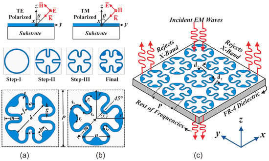
Figure 1.
The design evolution process of the proposed FSS shield: (a) Optimized FSS resonant structure; (b) FSS element rotated at ; (c) a element array illustrating operation principle of the FSS, rejecting X-band signals while being transparent to other frequencies.

Table 1.
Optimized design variables of the convoluted FSS.
FSS Unit Cell Rotation at
Figure 1b specifies the FSS element is rotated at an angle of = to evaluate its electromagnetic performance against the polarization of the incident waves. The FSS element, when rotated at , has a performance comparable to that of its unrotated counterpart for various oblique incident angles. However, it can be observed that the resonant frequency shifts to lower frequencies by 6%, along with a 5% increase in the operational bandwidth. Thus, unit cell rotation does not affect its electromagnetic performance because of its structural symmetry along the x- and y-axes.
3. Simulated Results and Discussions
This section presents the full-wave simulation results of the proposed FSS structure. Figure 2a manifests the spectral response of the FSS unit cell. The FSS resonates at 11.8 GHz and offers a stop bandwidth of almost 4 GHz. Figure 2b illustrates that incorporation of the U-shaped stub shifts the operating frequency to 8.6 GHz, but leads to a reduction in the rejection bandwidth. Thus, the edges of the resulting structure are chamfered and tuned to achieve the desired response around 10 GHz frequency, as shown in Figure 2c. Finally, inductive stub loading into the flower-like geometry broadens its operational bandwidth and enhances angular stability. The structure’s parameters are further optimized to obtain a response at 10 GHz, the X-band’s central frequency, as in Figure 2d.
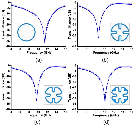
Figure 2.
Stepwise design evolution process of the FSS shield and its performance at normal incidence.
3.1. Shielding Effectiveness (SE)
The shielding effectiveness (SE) of an FSS shield refers to its ability to attenuate/block incident EM waves, as expressed in (1).
Figure 3 depicts the SE of the FSS obtained from the EM simulations and ADS. The FSS offers an effective shielding not less than 33 dB at the operating frequency.
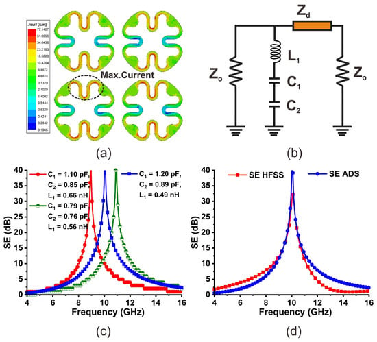
Figure 3.
(a) The surface current distribution at FSS surface; (b) equivalent circuit model of the FSS shield; (c) ADS simulations, conducted to achieve an optimized response; (d) a comparison of SE of ECM and EM models.
3.2. Surface Current Density
The surface current density (J-Surf) of the FSS array obtained at 10 GHz frequency, under normal incidence (TEz-0°), for the TE mode is shown in Figure 3a. The current distribution reveals that the current is more saturated at the U-shaped stubs at the FSS surface. This current intensity indicates inductance while the slots contribute to capacitance.
3.3. Equivalent Circuit Model (ECM)
An equivalent circuit model of the proposed FSS shield designed in ADS is illustrated in Figure 3b. The ECM of the FSS is a series combination of lumped components (, , and ). The metal/trace mainly contributes to inductance, whereas the inter-element spacing and etched slots on the FSS surface are modeled as capacitance. The employed dielectric is modeled as a transmission line. Moreover, is the characteristic impedance of free space on either side of the FSS. The surface impedance of the FSS can be expressed as
Several simulations are conducted in ADS to obtain the desired response of the ECM at the operating frequency. The optimized lumped circuit parameters, obtained through the curve fitting method, are listed in Table 2. However, alternative combinations of the lumped values may also yield a similar response at 10 GHz. Figure 3d presents a comparison of the SE curves of the circuit and EM models.

Table 2.
Lumped parameters obtained from ADS.
3.4. Polarization Stability
Figure 4a presents the shielding characteristics of the optimized FSS stopband filter at normal incidence for the TE and TM polarization. The FSS reveals identical spectral responses, achieving attenuation of more than 33 dB at the resonant frequency, with a rejection bandwidth of 26% for the TE and TM modes. In addition, Figure 4b,c manifest SE curves of the FSS surface over varying oblique incidences and polarizations. The incident angle is varied with a step size of . It can be noticed that the performance of the FSS remains unaffected by variations in angle. However, the attenuation and suppression bandwidth increase as the incident angle of the EM waves rises. Further, a transmission zero appears at about 16 GHz for incidences of and , which does not affect FSS operation in the band of interest. Furthermore, the EM performance of the rotated FSS structure is also verified over incident-angle variations. Figure 5a specifies the FSS responses at normal incidence for the TE and TM polarization states. It is observed that rotated FSS operates at a frequency of 9.4 GHz, as the inter-element spacing in this configuration becomes smaller . This reduction shifts the resonant frequency toward the lower frequency band and improves the stop bandwidth by 5%. The FSS offers a suppression bandwidth of 31%, with an attenuation of 33 dB, at the operating frequency at normal incidence. Figure 5b,c illustrate the SE curves of the FSS over incident-angle variations for TE and TM modes, respectively. The notch selectivity and rejection bandwidth improve with larger oblique angles. The FSS ensures similar performance for the TE and TM polarizations of the wave due to its fourfold symmetric geometry.
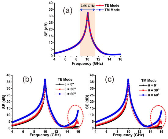
Figure 4.
(a) SE of FSS for TE and TM modes at the normal incident angle; (b) SE of the FSS for the TE mode, ensuring angular stability; (c) SE of FSS for TM mode, confirming wide-angle performance.
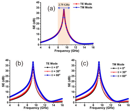
Figure 5.
(a) SE of the FSS element rotated at for TE and TM modes at ; (b) SE of the FSS for TE mode, verifying its angular stability up to ; (c) SE of FSS at various oblique angles for TM mode.
3.5. Parametric Analysis
The performance of the FSS shield is analyzed by tuning and optimizing various geometric parameters. Figure 6a shows the impact of varying the length of the U-shaped stubs. Increasing the length shifts the resonance frequency downwards, helping to achieve a miniaturized unit cell, also resulting in a reduction in operational bandwidth. Figure 6b illustrates that fine-tuning the radius helps to accomplish the desired FSS performance. Moreover, inter-element spacing also has a profound effect on the FSS’s response. Smaller inter-element spacing results in wider bandwidth and higher angular stability, and avoids the early onset of grating lobs, depending on the physical geometry of the FSS. Figure 6c specifies that an increase in inter-element spacing reduces the SE and rejection bandwidth while shifting the resonant frequency towards higher frequencies.
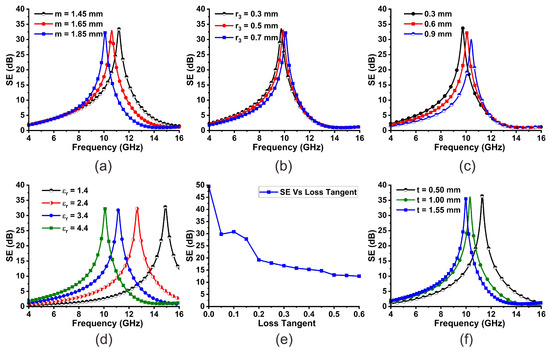
Figure 6.
(a) SE of the FSS by optimizing U-stubs length. (b) Impact of radius on the SE. (c) SE of FSS as a function of inter-element spacing. (d) Permittivity effect on FSS performance. (e) SE analysis as a function of loss tangent. (f) Thickness effect on SE behavior of the FSS.
In addition, the SE behavior of the FSS was also investigated by varying characteristics of the employed dielectric material. It can be seen in Figure 6d that the SE curves shift to higher frequencies with a decrease in permittivity of the dielectric. The results in Figure 6e reveal that the FSS achieves SE of more than 45 dB when the loss tangent of the substrate has a minimum value. The SE decreases as the loss tangent increases. Furthermore, increasing the thickness of the dielectric does not impact the SE of the FSS, but it shifts the resonant frequency to lower frequencies, as shown in Figure 6f.
4. Prototype Fabrication and Measurements
4.1. Measurement Setup
To assert the full-wave simulated results of the proposed FSS shield, a prototype consisting of unit cells was fabricated on a 1.55 mm thick FR-4 substrate, as depicted in Figure 7a. Techniques like the waveguide [28], anechoic chamber [29], and free space [30] can be used to evaluate the electromagnetic performance of an FSS surface, depending on the specific application, frequency range, and required measurement accuracy. Since FSSs interact with spatial electromagnetic waves in free space, a free-space measurement setup was employed in this article to ensure more realistic conditions and achieve more accurate results, as reported in [31].
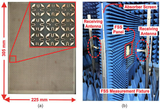
Figure 7.
(a) A photograph of the fabricated FSS prototype with a zoomed view; (b) schematic diagram of the measurement setup inside the anechoic chamber.
Figure 7b illustrates the measurement setup that consists of a pair of horn antennas positioned at a far-field distance on either side of the absorbing screen. The antennas, with an operating bandwidth of 6–18 GHz, are fixed at the same height and serve as transmitting and receiving antennas. In addition, they are connected to the ShockLine MS46322B vector network analyzer (VNA) to measure the transmission response of the FSS filter. The experimental setup is calibrated through the aperture in the absorbing screen without the FSS sample to account for the cable and free-space propagation losses. These losses are later subtracted from the measured results to eliminate the effect of attenuated microwave signals. Subsequently, the fabricated FSS array is fixed in the aperture of the absorbing screen and its transmission responses in terms of are measured for different incident angles.
Moreover, the shielding effectiveness of the FSS is determined using the magnitude of the measured in dB, expressed as
4.2. Measured Results
Figure 8a,b specify a comparison of the simulated and measured SE of the fabricated FSS panel for the TE and TM polarization modes under normal incidence. Since the cell design is compact and fourfold symmetric, it manifests consistent performance for both the x- and y-polarized waves. The results demonstrate that the FSS efficiently shields EM waves, with adequate suppression of 35 dB at its operating frequency. A minor shift in the resonant frequency is observed in the measured results, which is associated with a finite array size, fabrication tolerance, material parameter differences, and measurement errors. In addition, the FSS is also tested for oblique angles up to , with a step size of . Figure 8c,d illustrate the SE-versus-frequency curves as a function of the oblique angle for the TE and TM wave modes, respectively. It can be noticed that the suppression level and the stop bandwidth improve with angle, ensuring wide-angle stability and polarization-insensitive spectral response for the proposed structure, making it suitable for selective shielding applications.
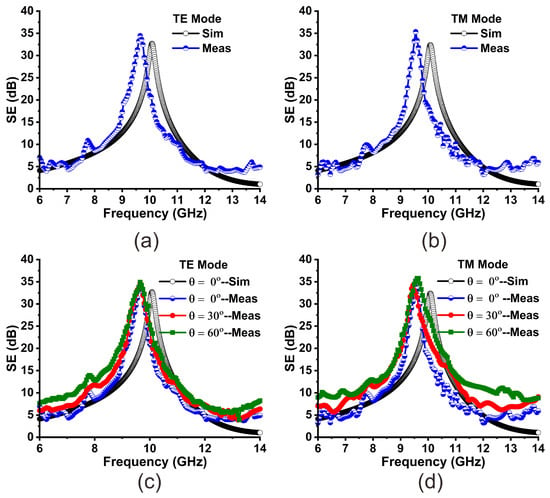
Figure 8.
FSS shielding performance: (a) TE mode at normal incidence; (b) TM mode at normal incidence; (c) SE-versus-frequency curves for the TE mode up to ; (d) SE plot for TM mode as a function of incident angle, ensuring angular stability.
5. Comparative Study
Table 3 shows a comparison of the proposed work with the most related works found in the literature. The comparison is carried out in terms of various parameters, such as unit cell size, geometry, supporting material, operating bandwidth, and angular stability, especially for the TM mode. The comparative study analysis reveals that most of the reported works have wide angular stability, provide good shielding performance, and have small dimensions. However, their shielding performance and the rejection bandwidth deteriorate with variations in the oblique angle, particularly for TM polarization mode. In contrast, the proposed FSS shield does not suffer from such shortcomings. It has a compact, fourfold symmetric structure, and angle variations do not affect its performance. Thus, it exhibits a highly stable, polarization-insensitive response for both the TE and TM wave modes up to , while maintaining a low profile. It can be used in two configurations as an additional feature.

Table 3.
Comparison of the proposed FSS shield with the available relevant designs.
6. Conclusions
In this paper, a miniaturized, polarization-insensitive, and rotation-independent FSS shield is introduced for EMI mitigation occurring at the X-band. The unit cell is composed of a fourfold symmetric convoluted geometry printed on a lossy dielectric. The FSS achieves a shielding effectiveness of 33 dB at 10 GHz frequency. Moreover, the design reveals wide angular stability up to and exhibits identical spectral characteristics for the TE and TM polarization states. It offers a fractional rejection bandwidth of 26% for the normal and 31% for the rotated configuration at normal incidence and effectively filters out X-band signals. A prototype containing unit cells is fabricated and tested over a wide range of incident angles for the TE and TM modes. The comparison of the results shows that the proposed FSS shield is a good candidate for selective/targeted EMI suppression applications. More importantly, the FSS is scalable to other frequencies and can be utilized in two design configurations.
Author Contributions
Conceptualization, methodology, software, validation, formal analysis, investigation, writing, measurement, data curation: M.I. Conceptualization, resources, measurement, review and editing, and supervision: Y.H. Measurement: Y.W. Review and editing: A.M. All authors have read and agreed to the published version of the manuscript.
Funding
This work was supported in part by the National Key Research and Development Program of China under Grant 2023YFE0107900, in part by the National Natural Science Foundation of China under Grant 62071306, and in part by the Shenzhen Science and Technology Program under Grants JCYJ20200109113601723, JSGG20210420091805014, and JSGG20210802154203011.
Institutional Review Board Statement
Not applicable.
Informed Consent Statement
Not applicable.
Data Availability Statement
The original contributions presented in the study are included in the article, further inquiries can be directed to the corresponding author.
Conflicts of Interest
The authors declare no conflicts of interest.
References
- Meenu, L.; Aiswarya, S.; Menon, K.U.; Menon, S.K. Experimental investigation to analyze the electromagnetic radiation exposure from wireless communication devices. J. Hazard. Mater. Adv. 2024, 17, 100548. [Google Scholar]
- Meenu, L.; Aiswarya, S.; Menon, S.K. A Survey on Heating Effects of Electromagnetic Radiation on Human Body. In Proceedings of the 2020 5th International Conference on Computing, Communication and Security (ICCCS), Patna, India, 1–4 January 2020. [Google Scholar]
- Sheng, X.; Wang, H.; Liu, N.; Wang, K. A Conformal Miniaturized Bandpass Frequency-Selective Surface with Stable Frequency Response for Radome Applications. IEEE Trans. Antennas Propag. 2024, 72, 2423–2433. [Google Scholar] [CrossRef]
- Qu, M.; He, Z.; Su, J.; Nayyeri, V. A Rasorber With Energy-Selective Passband and Ultrawideband Absorptive Out-of-Band. IEEE Trans. Microw. Theory Technol. 2024, 72, 5643–5652. [Google Scholar] [CrossRef]
- Li, M.; Hu, W.; Yang, X.-X.; Yi, Z. An Ultra-Wideband Absorber Based on Mixed Absorption Mechanisms. IEEE Trans. Antennas Propag. 2023, 71, 10009–10013. [Google Scholar] [CrossRef]
- Li, H.; Xu, J.; Nan, Y.; Chen, Q.; Zhou, C. Low-Profile Dual-Band Shared-Aperture Base Station Antennas Based on FSS Radiators. IEEE Antennas Wirel. Propag. Lett. 2024, 23, 1894–1898. [Google Scholar] [CrossRef]
- Ren, J.; Wang, Z.; Sun, Y.-X.; Huang, R.; Yin, Y. Ku/Ka-Band Dual-Frequency Shared-Aperture Antenna Array with High Isolation Using Frequency Selective Surface. IEEE Antennas Wirel. Propag. Lett. 2023, 22, 1736–1740. [Google Scholar] [CrossRef]
- Varshney, A.; Gençoğlan, D.N. High-Gain Multi-Band Koch Fractal FSS Antenna for Sub-6 GHz Applications. Appl. Sci. 2024, 14, 9022. [Google Scholar] [CrossRef]
- Hwang, D.H.; Jeong, T.; Kim, J.H.; Hwang, K.C. Band-Pass and Band-Stop Filter Frequency Selective Surface with Harmonic Suppression. Appl. Sci. 2024, 14, 6633. [Google Scholar] [CrossRef]
- Yang, Z.; Hu, W.; Jiang, W.; Luo, Q.; Huang, Q. High-Selectivity FSS with Wide Stopbands for EMI Suppression in Wireless Power Transfer Systems. IEEE Antennas Wirel. Propag. Lett. 2024, 23, 3832–3836. [Google Scholar] [CrossRef]
- Zhang, P.-P.; Zhao, Y.; Zhu, X.-C.; Chen, R.; Chu, P. A Single-Layer Vialess Polarization Rotation Reflective Surface with High-Frequency Selectivity. IEEE Antennas Wirel. Propag. Lett. 2023, 22, 1089–1093. [Google Scholar] [CrossRef]
- Abdollahvand, M.; Keyvan, F.; Jose, A.E.; Zahra, A.; Eduardo, M.d.R. A 20/30 GHz reflectarray backed by FSS for shared aperture Ku/Ka-band satellite communication antennas. IEEE Antennas Wirel. Propag. Lett. 2020, 19, 566–570. [Google Scholar] [CrossRef]
- Idrees, M.; Buzdar, S.; Khalid, S.; Khalid, M.A. A Novel Miniaturized Frequency Selective Surface for EMI Shielding Applications. In Proceedings of the 2021 International Bhurban Conference on Applied Sciences and Technologies (IBCAST), Islamabad, Pakistan, 12–16 January 2021. [Google Scholar]
- Dey, S.; Dey, S. Conformal Miniaturized Angular Stable Triband Frequency Selective Surface for EMI Shielding. IEEE Trans. Electromagn. Compat. 2022, 64, 1031–1041. [Google Scholar] [CrossRef]
- Ghosh, S.; Srivastava, K.V. Broadband Polarization-Insensitive Tunable Frequency Selective Surface for Wideband Shielding. IEEE Trans. Electromagn. Compat. 2018, 60, 166–172. [Google Scholar] [CrossRef]
- Hakim, M.L.; Islam, M.T.; Alam, T. Incident Angle Stable Broadband Conformal mmWave FSS for 5G (n257, n258, n260, and n261) band EMI Shielding Application. IEEE Antennas Wirel. Propag. Lett. 2023, 23, 488–492. [Google Scholar] [CrossRef]
- Darvish, A.; Kishk, A.A. X-Band Nearfield Shielding Metasurface with Adjustable Reflection/Transmission Zeroes. IEEE Trans. Electromagn. Compat. 2022, 64, 1602–1613. [Google Scholar] [CrossRef]
- Yang, Y.; Li, W.; Salama, K.N.; Shamim, A. Polarization Insensitive and Transparent Frequency Selective Surface for Dual Band GSM Shielding. IEEE Trans. Antennas Propag. 2021, 69, 2779–2789. [Google Scholar] [CrossRef]
- Murugasamy, L.; Sivasamy, R. A Single Layer Interdigitated Loop Elements-Based Miniaturized Frequency Selective Surface for WLAN Shielding. IEEE Trans. Consum. Electron. 2024, 70, 617–626. [Google Scholar] [CrossRef]
- Natarajan, R.; Sivasamy, R.; Gunasekar, A. A compact polarization independent stop band frequency-selective surface for WLAN shielding. Microw. Opt. Technol. Lett. 2024, 66, e34097. [Google Scholar] [CrossRef]
- Chellaiah, E.; Kannan, M. An ultra-thin frequency-selective surface with inductive loading for X-band shielding applications. Int. J. Commun. Syst. 2024, 36, e5699. [Google Scholar] [CrossRef]
- Idrees, M.; He, Y.; Zhang, Z.; Wong, S.-W. A Compact Single-Layer Frequency Selective Surface for Ultrawideband Shielding (Invited Paper). In Proceedings of the 2023 IEEE 11th Asia-Pacific Conference on Antennas and Propagation, Guangzhou, China, 22–24 November 2023. [Google Scholar]
- Yun, D.-J.; Hong, Y.-P.; Lee, I.-H.; Kim, M.-S.; Lee, J.-C.; Hwang, I.-J. A Multifunctional Frequency Selective Surface with a Wide Incident Angle for X-/K-/Ka-Band Applications. IEEE Antennas Wirel. Propag. Lett. 2024. [Google Scholar] [CrossRef]
- Venkatesh, G.; Thottappan, M.; Singh, S.P. Highly Angularly Stable Dual-Band Stop FSS for Blocking Satellite Downlink Frequencies. IEEE Trans. Electromagn. Compat. 2022, 64, 2055–2059. [Google Scholar] [CrossRef]
- Idrees, M.; He, Y.; Ullah, S.; Wong, S.-W. A Dual-Band Polarization-Insensitive Frequency Selective Surface for Electromagnetic Shielding Applications. Sensors 2024, 24, 3333. [Google Scholar] [CrossRef] [PubMed]
- Tang, L.; Wang, C.; Yan, L.; Gao, R.-K.; Zhao, X.; Liu, C. Optically transparent and angularly stable broad-stopband frequency selective surface for millimeter wave electromagnetic interference mitigation. Microw. Opt. Technol. Lett. 2024, 66, e34078. [Google Scholar] [CrossRef]
- Hakim, M.L.; Alam, T.; Islam, M.T. Polarization-Insensitive and Oblique Incident Angle Stable Miniaturized Conformal FSS for 28/38 GHz mm-Wave Band 5G EMI Shielding Applications. IEEE Antennas Wirel. Propag. Lett. 2023, 22, 2644–2648. [Google Scholar] [CrossRef]
- Gunaydin, O.F.; Can, S. Optically Transparent Frequency Selective Surfaces with Wideband Capability for IoT Applications: A Polarization-Independent Double-Layer Design. Sensors 2024, 24, 4724. [Google Scholar] [CrossRef]
- Cardillo, E.; Carcione, F.L.; Ferro, L.; Piperopoulos, E.; Mastronardo, E.; Scandurra, G.; Ciofi, C. Development of a Simple Setup to Measure Shielding Effectiveness at Microwave Frequencies. Sensors 2024, 24, 3741. [Google Scholar] [CrossRef]
- Expósito, I.; Reis, J.R.; Viegas, S.; Caldeirinha, R.F.S.; Cuiñas, I.; Sánche, M.G. Analysis of selective surfaces characterization using free-space technique. Measurement 2025, 246, 116719. [Google Scholar] [CrossRef]
- Micheli, D.; Gianola, P.; Bertin, G.; Delfini, A.; Pastore, R.; Marchetti, M.; Diana, R. Electromagnetic Shielding of Building Walls: From Roman times to the present age. IEEE Antennas Propag. Mag. 2016, 58, 20–31. [Google Scholar] [CrossRef]
Disclaimer/Publisher’s Note: The statements, opinions and data contained in all publications are solely those of the individual author(s) and contributor(s) and not of MDPI and/or the editor(s). MDPI and/or the editor(s) disclaim responsibility for any injury to people or property resulting from any ideas, methods, instructions or products referred to in the content. |
© 2025 by the authors. Licensee MDPI, Basel, Switzerland. This article is an open access article distributed under the terms and conditions of the Creative Commons Attribution (CC BY) license (https://creativecommons.org/licenses/by/4.0/).