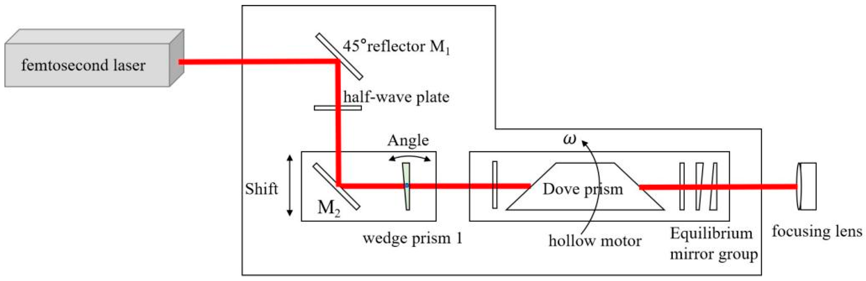
3.1. Analysis of Inherent Errors in Helical Drilling Systems
The error of the helical drilling system is mainly composed of light spot shape error and mechanical rotation error. The laser light spot is not circular after being focused by the objective lens but is an approximate ellipse, as shown in
Figure 5a. As the Dove prism rotates, the light spot also rotates, at twice the speed of the prism. The pore wall of the processed hole is not always cut by the same position of the light spot circumference. Therefore, the roundness error of the light spot shape will be reflected on the roundness error of the processed hole. The spot shape error is mainly caused by the quality of the laser beam and the lens light. At the same time, the light spot shape is also not consistent at different positions along the cutting trajectory, and this difference can also affect the roundness error of the processed hole. As shown in
Figure 5a, there is an obvious difference in the shape of the light spot at 0° and 180° positions. The latter is significantly larger than the former. This will cause a change in the width of the cutting path when the light spot rotates, as shown in
Figure 5b. The left cutting path is significantly wider than the right cutting path. The more irregular the shape of the spot, the greater the roundness error. The errors above, combined with the rotational errors of the mechanical system, will ultimately affect the roundness error of the processed hole. According to the width variation of the cutting path in
Figure 5b, theoretically, if all materials on the cutting path are removed, the roundness error is about 7 µm. However, because the size of the spot in
Figure 5 includes a large heat-affected zone, the actual roundness error will be less than 7 µm, if only the focus spot size or Rayleigh length range is considered. The size of the heat-affected zone is around 50 µm. Observing the completely burned-through area of the material in a single spot in
Figure 5a, the diameter of the focus spot in this system is about 20–25 µm; this is consistent with the theoretical value mentioned in
Section 2. If the ablation threshold of the material is considered, and the material is strictly removed just at the focal point, the final hole roundness error is about 3~5 µm in our helical drilling system. Good dynamic balance is an effective way to overcome spot rotational errors when the helical drilling system leaves the factory.
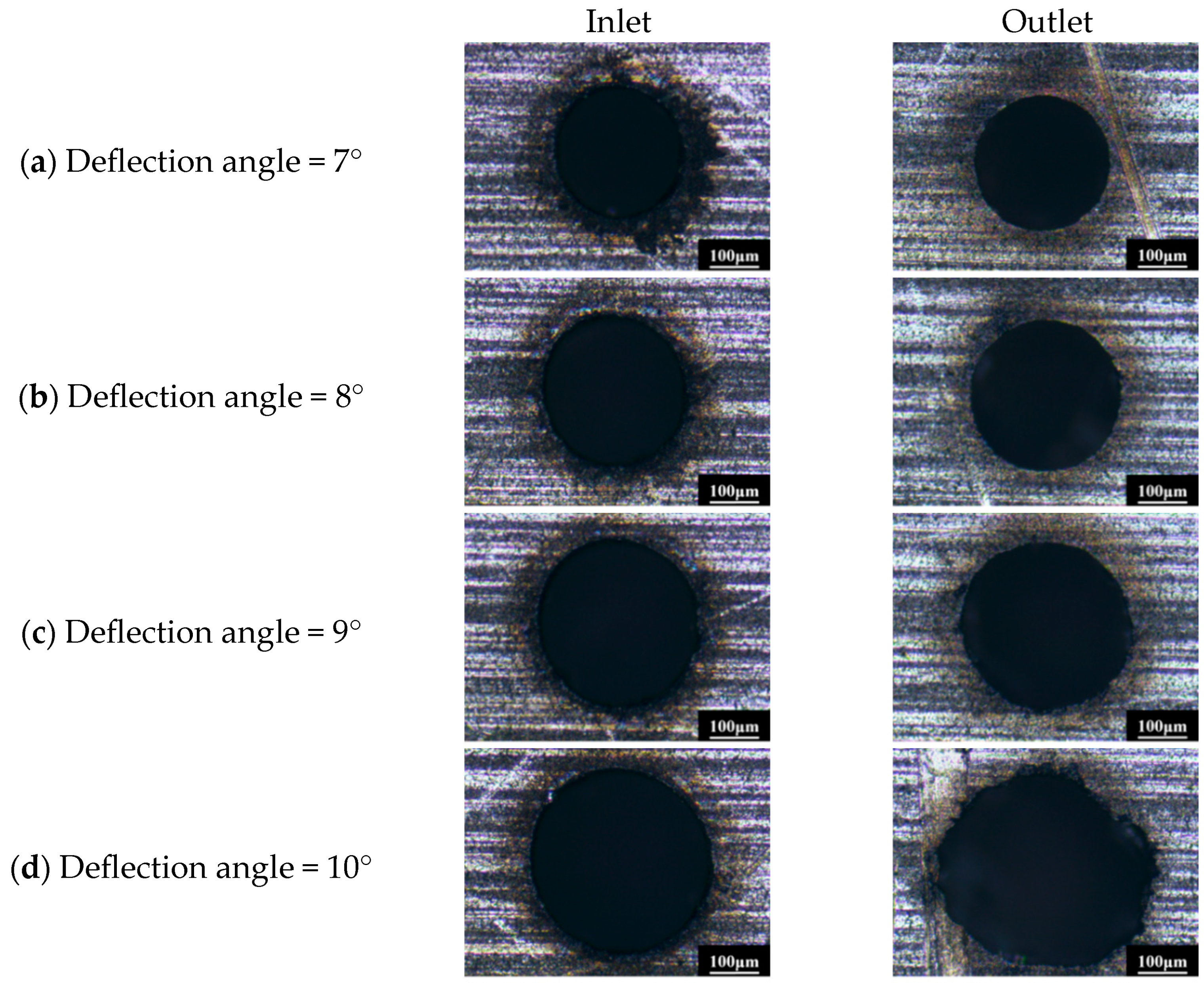
3.2. Analysis of the Influencing Factors of Inlet and Outlet Morphology
When the laser power and repetition frequency are constant, namely, the laser parameters are fixed, the influence of the helical drilling system parameters on the inlet morphology of the micro-hole is as shown in
Figure 6. As shown in
Figure 6, the inlet diameter gradually increases as the deflection angle of the wedge prism increases, but it is not a linear relationship. This is consistent with the helical drilling principle introduced in
Section 2. In fact, the diameter of the hole inlet is also related to another factor, which is the distance at which the focus spot moves down during the drilling process. In order to completely cut off the material at the outlet of the micro-hole on the thick plate, the focus spot must be lowered to the position approximately one Rayleigh length from the outlet. When the focus spot shifts downwards, the size of the hole inlet will increase, and the increase extent is related to the axial light intensity distribution of the Gaussian spot. In order to study the effects of helical drilling system parameters on the size of the micro-hole, the downward distance of the focus spot was set as 0.43 mm, according to the thickness of the processed plate and the Rayleigh length of the laser.
In
Figure 6, although the inlet sizes are different, the edge morphology of all micro-holes is similar. There is always a certain degree of roundness error, and the error direction is also the same. This can prove that roundness error is mainly caused by mechanical rotation system errors and spot non-uniformity errors, and the reasons have been discussed in
Section 3.1. In addition, it can be observed that there are obvious discoloration regions at the edges of the hole inlets with different wedge prism deflection angles, but the width difference of the discoloration regions is not dramatic. This is mainly because the laser mean power density at the inlet of each micro-hole is theoretically the same, if the move-down distance of the focus spot is fixed, and the morphology differences of focal spots with different wedge prism deflection angles are ignored. The discoloration zone is actually composed of two parts. One part is the heat affected zone, and the other part is the surface oxidation zone, as shown in the blue area in
Figure 6. Surface oxidation is an inevitable defect in the air environment for ablation processing methods, but it can be eliminated by using inert gas protection.
The outlet of the processed hole is a more important feature than the inlet, because, from the perspective of practical application of film cooling holes, the outlet of laser drilling is exactly the inlet of cooling airflow, and the flowing state of airflow inside the hole is directly affected by the shape of the inlet. In addition, outlets are also most susceptible to process factors such as blowing pressure, slag discharge conditions, depth to diameter ratio, etc. The influencing factors of outlet morphology should be analyzed in detail. In
Figure 6, the diameter of the outlet increases with the increasing of the wedge prism deflection angle, and there is also an oxidation discoloration area around the outlet, which is consistent with the inlet. When the deflection angle is less than 10°, it can be clearly observed that the cutting quality of the outlet edge is significantly better than that of the inlet edge. The outlets have clear edges, good roundness, and few notches. This is mainly because when the Z-axis descends to complete the drilling, the laser power density at the inlet gradually decreases, although it is all above the material’s ablation threshold. That is, the inlet goes through a long ablation process, and the orifice size increases from small to large. But the outlet edge is cut under a certain power density without obvious change, so the thermal ablation time is relatively short. Meanwhile, when the outlet edge is cut, the slag-removal channel has already been opened, which is another reason why the quality of the outlet edge is better than that of the inlet edge. However, when the deflection angle of the wedge-shaped prism is 10°, it can be observed that the outlet edge begins to become irregular, with obvious notches appearing in a serrated shape and with a large amount of uncut material. The main reason for this phenomenon is that as the prism deflection angle increases, the diameter of the micro-hole increases, and thus, the overlap rate of the laser spot decreases. The decrease of spot overlap rate will lead to a decrease in the mean power density at a certain point along the cutting path, which makes it impossible to achieve complete and quick material removal, and, at last, results in serrated edge defects. It can also be found that the inlet morphology is better than the outlet morphology with the same spot overlap rate when the deflection angle of the wedge-shaped prism is 10°. This is mainly because the mean power density for the cutting inlet edge is far higher than that for the outlet, considering the set of the Z-axis downward distance. Although the inlet mean power density also decreases with the decrease of the spot overlap rate, it is still above the material’s ablation threshold, so the inlet morphology is not significantly affected by the spot overlap rate. According to the discussion above, the decrease of the mean power density caused by the decrease of the spot overlap rate seems to be the reason for the deterioration of the outlet morphology.
To further investigate the effect of the spot overlap rate on the outlet morphology, the deflection angle of the wedge-shaped prism was fixed, and the rotation speed of the Dove prism was changed. The outlet morphology is shown in
Figure 7. With the increase of Dove prism rotation speed, notches begin to appear at the outlet edge, and serrated defects gradually become apparent. From Equation (7) and
Figure 4, it can be found that as the rotation speed of Dove prism increases, the laser spot overlap rate decreases; namely, the distance between adjacent pulses on the cutting trajectory increases. Because the laser parameters and the diameter of the micro-hole have not changed, the mean power density in a certain cutting area remains unchanged, but its instantaneous power density in the local area decreases. This is the fundamental reason why the material cannot be completely and quickly removed. From the discussion above, it can be seen that the decrease in spot overlap rate and mean power density, which leads to the deterioration of outlet quality, is just superficial. The fundamental reason is the decrease of instantaneous power density at a specific processing area. The instantaneous power density is a key factor in improving the quality of the outlet edge. The formula for calculating the instantaneous power is
where
V is the rotation speed of the Dove prism,
L is the circumference of the cutting track, and
P is the laser output power.
To verify the effect of instantaneous power density on outlet morphology, the rotation speed of the hollow motor was fixed, and the laser power was changed. Of course, the spot overlap was also fixed under these experimental conditions. The results are shown in
Figure 8. As the laser power decreases, the instantaneous power density decreases accordingly, the outlet edge gradually becomes irregular, the roundness deteriorates, and large areas of material not removed appear at the edge of the outlet. When the laser power increases, the outlet edge quality is significantly improved. Thus, the important influence of instantaneous power density on the outlet morphology was verified.
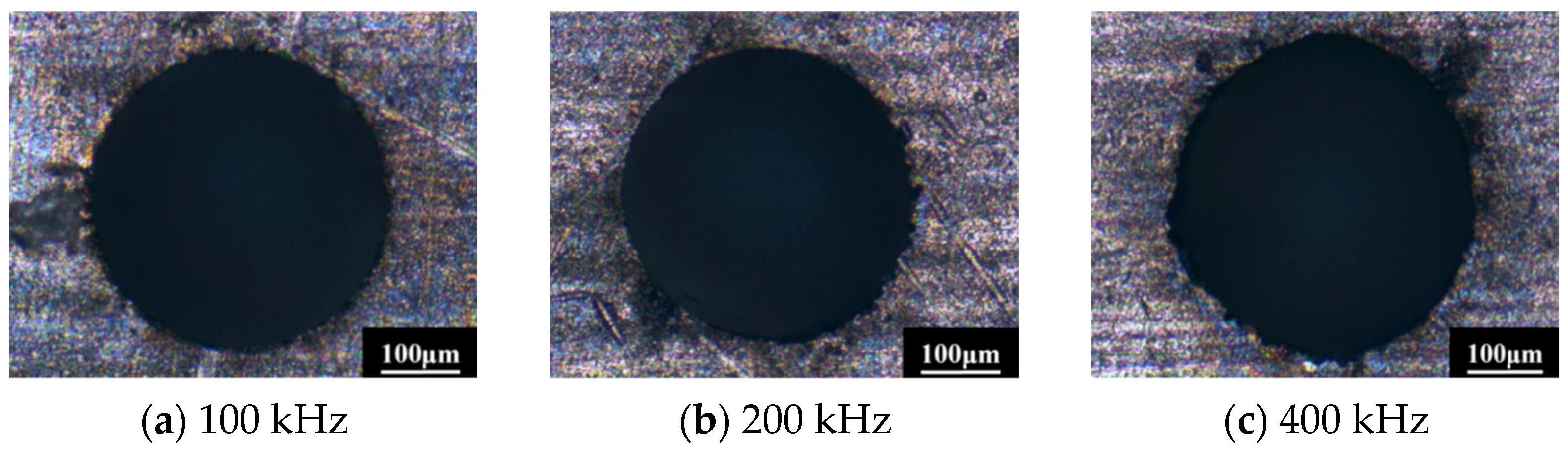
When the laser power and Dove prism rotation speed remain constant, the instantaneous power density will be affected by the laser repetition frequency. As the repetition frequency increases, the number of pulses increases, and the overlap rate of the light spot increases, but the energy of a single pulse decreases; that is, the instantaneous power density at a certain area along the cutting path will decrease, which prefigures that the processing quality at the outlet edge of the hole will also decrease.
Figure 9 shows the processing results of changing the laser repetition frequency, which well confirms the above conclusions. If the rotation speed of the Dove prism is 2000 rpm when the repetition frequency is 100 kHz, the overlap rate of the laser spot is 0, and there is no overlapping area between the two adjacent laser pulses, but the morphology of the hole exit is better. When the repetition frequency is 400 kHz, the overlap rate of the spot is 45.49%, but the morphology of the hole exit is poor. This is mainly because when the repetition frequency changes from 100 kHz to 400 kHz, the peak power density of the laser will decrease to a quarter of the original. Although the spot overlap rate increases about 45%, the instantaneous power density still decreases in a certain processed area. The instantaneous power density directly determines whether the material can be removed quickly.
Based on the discussion above, if the speed of the hollow motor is fixed at the state with a good dynamic balance, and in order to obtain the better outlet morphology, a lower repetition frequency should be selected in combination with higher laser power. But the entrance morphology is also something we need to consider comprehensively.
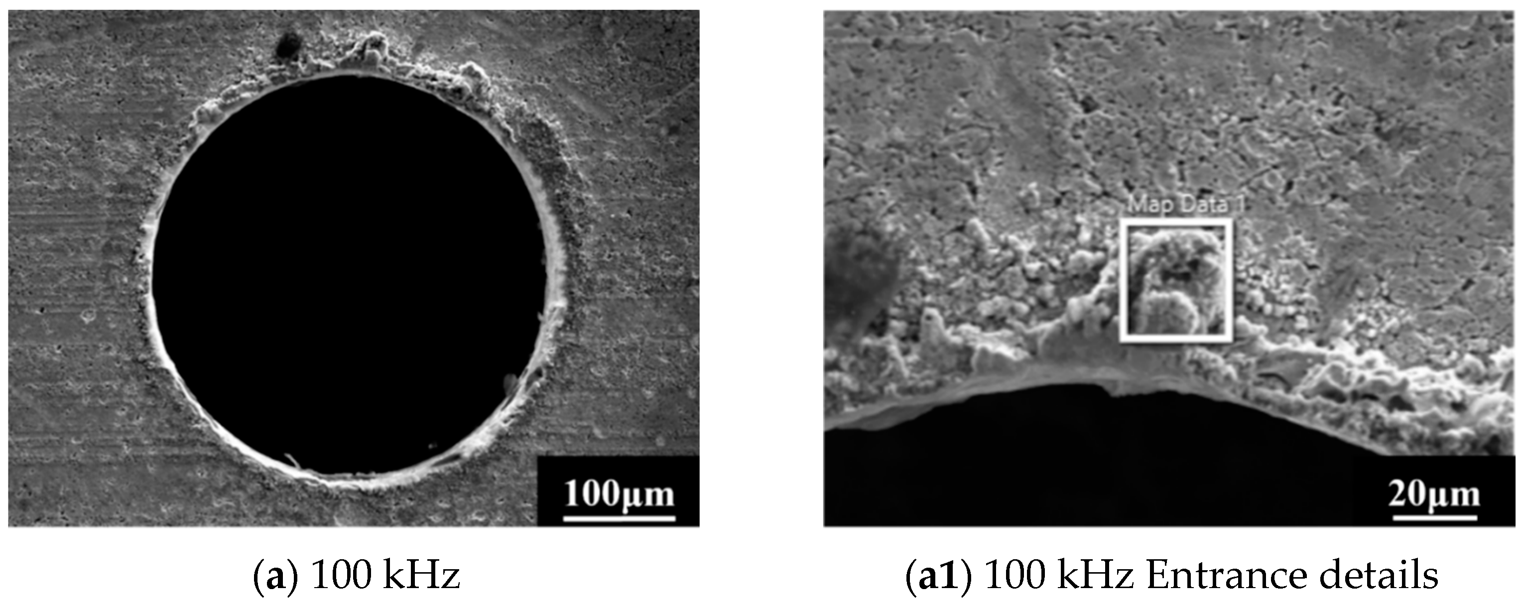
Figure 10 shows the original inlet morphology of the micro-hole obtained by different repetition frequencies at a power of 10 w. It can be observed that the lower the repetition frequency, the more severe the splashing phenomenon on the surface. A large amount of melted and re-solidified slag accumulates on the inlet surface, while these defects are much milder when the repetition frequencies are higher. This is mainly because the lower the laser repetition frequency, the higher the peak power density, and the more intense the interaction between the laser and the material. The higher the temperature and pressure inside the molten pool, the greater the amount of spraying towards the surroundings. In the case where the slag discharge channel has not yet been opened, the sprayed slag will accumulate on the inlet surface, leading to a deterioration of the entrance morphology. After the outlet is opened, the slag can be discharged in a timely manner with the protective gas, so it does not have significant impact on the morphology of the outlet. During the actual drilling process of blade air film holes, a layer of protective material is pre-coated on the surface of the blade to prevent oxidation and discoloration of the substrate. After the processing is finished, the coating material is removed, and part of the slag at the hole inlet is also removed, and the morphology of the inlet edge is improved. Therefore, the influence of repetition frequency on the inlet morphology can sometimes be disregarded in the actual drilling process.
In summary, the rotation speed of the Dove prism, laser power, and laser repetition frequency all affect the quality of the helical drilling hole by changing the spot overlap rate or mean power density. However, the instantaneous power density acting on the processed area is the essential factor determining the orifice morphology of the hole, especially the outlet. When the instantaneous power density is low, the outlet material cannot be completely removed, and the thermal accumulation effect will be enhanced during the drilling. The proportion of material removed by melting is large, and the outlet edge morphology is relatively poor. When the instantaneous power density increases, the proportion of material removed by evaporation increases, and the outlet morphology can be improved dramatically.
3.3. Analysis of the Hole Wall Recast Layer
The recast layer inside the film cooling holes of turbine blades in aircraft engines has a significant impact on the performance of the blades. On the one hand, the recast layer will damage the integrity of the hole wall surface. The protrusions and pits in the recast layer will increase the roughness of the processed surface, affecting the state of the airflow inside the gas film hole and thus affecting the cooling effect. On the other hand, micro-cracks inside the recast layer will gradually expand and fracture during the high-speed rotation of the blade, which seriously reduces the expected life of the blade. Therefore, the recast layer is a necessary element to be considered in the drilling process of gas film holes. For long pulse lasers, the energy absorbed by the material has sufficient time to be converted from light energy to thermal energy and expands around the processed area to form a liquid melt pool. Part of the liquid metal in the molten pool is removed in the form of steam, while another part is directly blown away by the protective gas. The remaining part solidifies and adheres to the hole wall after the laser spot is moved away and then forms a recast layer. For ultra-fast lasers such as femtosecond lasers, the pulse irradiation time usually is shorter than the material’s thermal relaxation time. The material removal mechanism changes from thermal melting removal to direct removal by plasma vapor based on the multi-photon absorption. Therefore, theoretically, the ultra-fast laser processing will not produce thermal damage, such as recast layers and heat-affected zones. However, for micro-holes with large depth-to-diameter ratios, such as gas film holes, as the processing depth increases, the protective air pressure decreases, and the metal vapor cannot be discharged from the hole interior in a timely manner, which will condense and adhere to the hole wall. At the same time, the shielding effect of the hole wall on the incident laser will also reduce the instantaneous power density, leading to a strong thermal accumulation effect, promoting the thermal melting of the material, and forming a recast layer after cooling. Although the multi-step method is able to reduce the recast layer to some extent, it obviously increases the processing time about three times that of the one-step method and seriously decreases the efficiency, which is an important element in practical application.
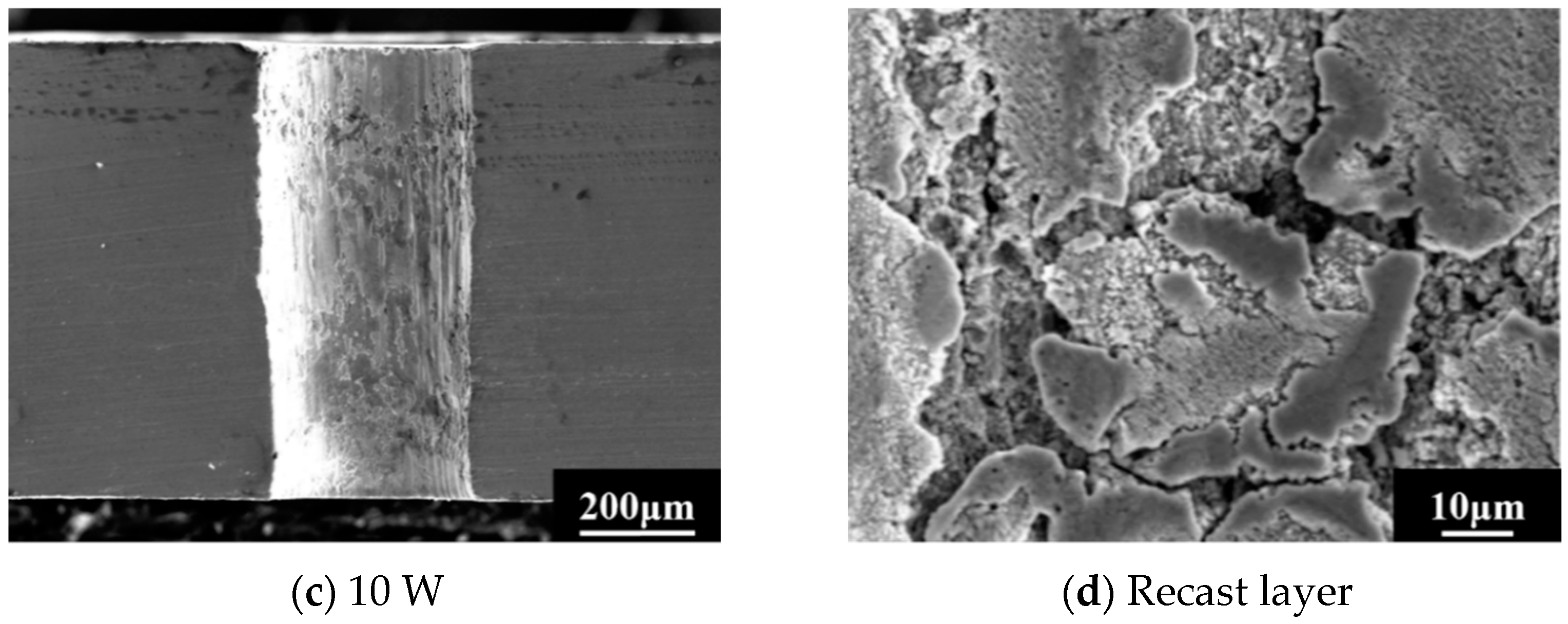
Figure 11 shows the cross-sections of gas film holes processed with different laser powers at a laser repetition frequency of 400 kHz. From the figure, it can be observed that there are recast layers on the sidewall surfaces. The presence of the recast layer increases the roughness of the sidewall surface. The severity of the recast layer near the inlet and outlet is different, and the re-condensation phenomenon near the outlet is significantly more severe than that near the inlet. This is mainly because the processing depth at the outlet is larger. The laser instantaneous power density is reduced due to the obstruction of the hole wall. Then, the thermal effect is enhanced, and the proportion of material removed as liquid increases, thereby aggravating the surface re-condensation phenomenon after cooling. In addition, it can also be found that the lower the power, the more severe the recast defects near the outlet. This is because the decrease in power leads to a decrease in instantaneous power density, thereby enhancing the thermal effect and removing the material in a molten state. This corresponds to the observed deterioration in low-power outlet morphology in the previous section. Another phenomenon that needs to be noted is that the inlet diameters of the micro-holes are the same under three different laser powers, but the outlet diameter of the micro-hole increases under low power, such as 7 W, which is related to the melting removal state of the material near the outlet under low power. The reduced power further leads to the enhancement of the heat effect near the outlet, and the liquid removal mechanism will cause the outlet to expand and reduce the orifice roundness. Therefore, it can be seen that low laser power not only leads to the deterioration in the morphology of the outlet but also affects the dimensional accuracy of the outlet. Therefore, it is advisable to avoid drilling gas film holes at low power as much as possible.
As shown in
Figure 11, it can also be observed that the roughness of the side wall is relatively large under high laser repetition frequency, which has a serious impact on the airflow state inside the gas film holes.
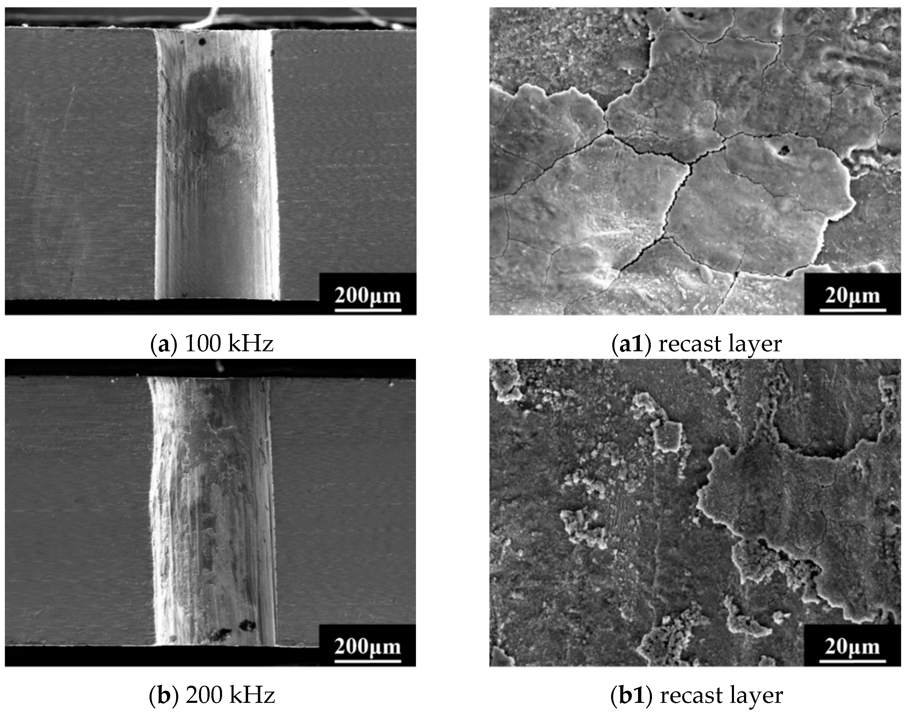
Figure 12 shows the drilling results with the laser repetition frequency of 100 kHz and laser power of 10 w. As shown in
Figure 12, reducing the repetition frequency can improve the roughness of the hole wall surface and change the recast layer distribution on the sidewall surface. The higher repetition frequency corresponds to the larger thermal effect, and the surface recast layer undergoes multiple melting and solidification processes, resulting in the increase of surface roughness, as shown in
Figure 12b,b1. Although the recast layer still exists at the repetition frequency of 100 KHz, the continuity of the recast layer is good, and the surface of the recast layer is relatively flat, with almost no repeated processes of re-solidification after multiple melting; thus, the surface of the hole wall is relatively smooth, as shown in
Figure 12a,a1. This is all attributed to the higher instantaneous power density of the laser corresponding to low repetition frequency and the consequent rapid material removal by evaporation with lower thermal effects.
The outlet surfaces of the micro-holes corresponding to
Figure 11c and
Figure 12a,b were polished, and the thickness of the recast layer was measured by SEM; the results are shown in
Figure 13. It can be observed that as the repetition frequency increases, the outlet edge begins to become irregular, with notches appearing and morphology deteriorating. This is consistent with the results observed by an optical microscope in the unpolished state of
Section 3.2. The thickness of recast layers corresponding to 100 kHz and 200 KHz are about 2 µm~3 µm, but the thickness of recast layer corresponding to 400 KHz is locally greater than 20 µm. And a large range of heat-affected zones and micro-cracks embedded in the matrix were observed; the width of the heat-affected zone is 20 µm. From this, it can be seen that although the higher repetition frequency can improve the surface morphology of the inlet, they will reduce the instantaneous power density of the laser and result in significant thermal effects, then cause thicker recast layers and other substrate defects, which are extremely detrimental to the performance of the blade film cooling holes. Therefore, considering the thickness of the recast layer and the probability of defects such as cracks appearing, low repetition frequency should be given priority in actual drilling. Due to the presence of recast layer less than 5 µm being allowed in practical application [
25], the efficient one-step method has a large application potential in blade production. Meanwhile, the processing times in the experiments above are all between 3 and 5 s, resulting in at least twice the efficiency improvement as the multi-step method.
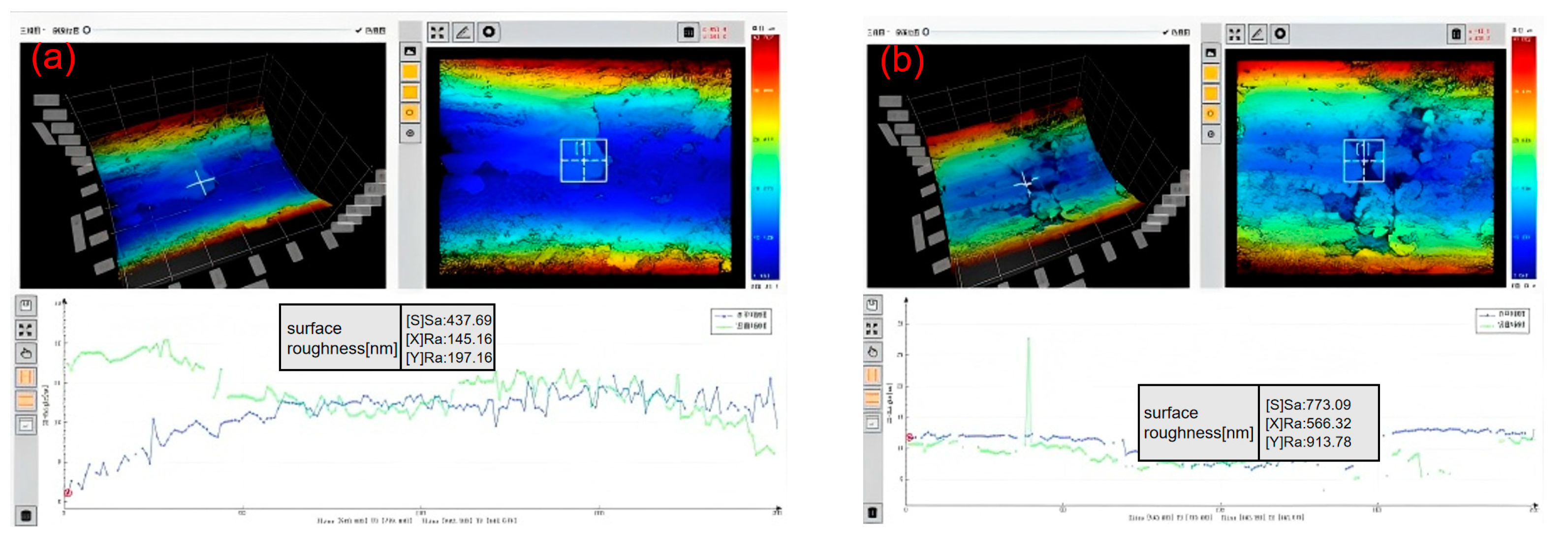
The local three-dimensional morphology of the sidewalls at 100 kHz and 400 kHz was measured by white light interferometer, and the results are shown in
Figure 14. The 3D surface roughness Sa corresponding to low repetition frequency is about 0.438 µm, which is significantly smaller than that corresponding to high repetition frequency; the latter is about 0.773 µm. This is consistent with the intuitive perception obtained from SEM images. In addition, from the contour curve of the 400 kHz sidewall, it can be observed that there are obvious recasting protrusions on the local area. These abnormal high points on the local sidewall have the most serious damage to surface integrity. They affect the internal airflow state of the gas film hole, cause turbulence, and thus affect the cooling effect. It is necessary to avoid the protrusion of recasting defects as much as possible. Although the surface of the gas film hole can be observed to be very rough from the three-dimensional morphology, the actual roughness value is similar to that of the mechanical grinding surface, with most 3D roughness values less than 0.8 µm. This also indicates that the gas film hole drilled by the ultra-fast laser can be applied in actual blade products.
In general, the instantaneous power density is the key factor affecting the quality of the orifice. In order to improve the roundness of the orifice and reduce the material defects of the orifice, a higher instantaneous power density should be selected, so it is necessary to choose a smaller rotation speed of the Dove prism, moderate deflection angles of wedge prism, larger power and smaller repetition frequency.


