Article

Alignment Optimization of Elastically Supported Submarine Propulsion Shafting Based on Dynamic Bearing Load Influence Numbers

Naval University of Engineering, Wuhan 430033, China
*
Author to whom correspondence should be addressed.
Appl. Sci. 2025, 15(8), 4348; https://doi.org/10.3390/app15084348
Submission received: 14 March 2025 / Revised: 9 April 2025 / Accepted: 11 April 2025 / Published: 15 April 2025
(This article belongs to the Section Marine Science and Engineering)

Abstract

:
The design scheme of elastically supported submarine propulsion shafting can effectively realize the attenuation of the vibration energy and improve the stealth performance of the whole submarine. However, the elastic deformation generated by the system will affect the alignment state of shafting, thus affecting its safety and reliability. Aiming at this problem, taking a certain elastically supported submarine propulsion shafting as the study object of this paper, the alignment calculation model of the shafting was established and validated, and an equivalent line-surface method was proposed to measure the elastic bearing displacement. On this basis, the concept of the dynamic bearing load influence numbers (BLINs) was elicited, and a response surface method using Gaussian process regression (GPR) was designed to establish the mapping relationship between the elastic displacement and the dynamic BLINs. Taking the equivalent displacements of the bearings as variables, the alignment optimization of the shafting was achieved by combining the genetic algorithm and the response surfaces. After optimization, the load of the rear stern bearing was reduced by 16.67%, and the standard deviation of the bearing loads was reduced by 37.19%. Hence, the alignment state of the shafting was improved. The studied results can provide theoretical and technical support for the analysis and optimization of the alignment characteristics of elastically supported submarine propulsion shafting.

1. Introduction

The quality of shafting alignment directly affects the invisibility, reliability, and safety of a submarine. A poor shafting alignment state will cause violent vibration, abnormal wear of the bearings, and even shaft deformation and fracture in severe cases [1]. With the requirements for the acoustic stealth of modern submarine continuously increasing, the design scheme of elastically supported submarine propulsion shafting has been proposed under this background. Various elastic vibration isolators, such as the large floating raft, the air spring, and the airbag isolator, are utilized for elastically supported submarine propulsion shafting to attenuate the vibration energy transmitted from the shafting to the hull, thus achieving the goal of vibration and noise reduction. In recent years, advancements in elastic support technology have catalyzed the development of novel vibration isolation isolators. Zhang et al. [2] developed an intelligent floating raft system incorporating automatic pressure-adjusting air springs. Integrating a fuzzy logic-based self-tuning PID controller with the magneto-rheological damper, Sharma et al. [3] established a semi-active vibration isolator used for marine diesel engine systems. Liu et al. [4] engineered a digital twin-driven air spring vibration isolation system for marine shafting featuring real-time alignment control. However, elastic vibration isolators will cause elastic deformation at the bearing supports of a shafting, which will change the deflection of the shafting and affect its alignment state. Therefore, it is necessary to precisely analyze the alignment characteristics of elastically supported submarine propulsion shafting and subsequently achieve alignment optimization based on the analytical results.
With the emergence and continuous development of the design scheme of elastically supported shafting, many scholars have begun to study the shafting alignment calculation under elastic boundary conditions, in order to obtain more scientific and accurate results. Deliporides et al. [5] developed finite element code for marine shafting alignment with the elasticity of the bearing supports considered, and analyzed the alignment state of a heavy shafting under rigid and elastic boundary conditions. Taking the ship hull deformation into account, Murawski [6] calculated the alignment state of a marine shafting, and believed that the stiffness and damping characteristics of the boundary conditions should be considered. Furthermore, he developed software for shafting alignment calculations under elastic boundary conditions using the finite element method [7]. Zhou [8] proposed the concept of elastic alignment for the propulsion shafting of ultra-large ships, and established an elastic alignment calculation model that incorporates elastic boundary conditions, including elastic hull deformation, as well as oil-film stiffness and damping of each bearing. Khalyavkin et al. [9] presented the design scheme of a ship shaft line on elastic supports with a coefficient of rigidity, and analyzed the influence of elastic properties of deadwood bearings on shaft line operability. Gu et al. employed [10] various aft stern tube bearing support models, and comparatively analyzed the alignment characteristics of a ship shafting with a large span of propeller shaft under different elastic support conditions.
The elastic deformation generated under elastic support conditions is an important dynamic factor affecting shafting alignment. Murawski [11] analyzed the displacement of a propulsion shaft line and a crankshaft axis caused by thermal deformation. Using the finite element method and the jack-up method, Seo et al. [12] analyzed the influence of hull deformation caused by draught change on the alignment of the shafting for a large ship, and believed that hull deformation is one of the key factors contributing to the bearings’ elastic displacements. Based on comprehensive calculations and analyses, Avgouleas et al. [13] pointed out that hull deflection and elastic deformation of strut bearings should be taken into account in the process of shafting alignment of a high-speed naval craft. Chen et al. [14] proposed a four-degree-of-freedom bearing support model to accurately describe the non-uniform dynamics behavior inside bearings, and investigated the effect of elastic bearing bush deformation on shafting alignment utilizing this model. The influence of elastic deformation on marine shafting alignment is presently a focal point of research. However, the measurement methods for elastic deformation of supporting foundations of marine shafting remain underdeveloped in terms of comprehensiveness and operational efficiency.
Emergent algorithms are being progressively applied to the control and optimization of shafting alignment [15,16]. The integration of optimization algorithms with the BLINs is a prevalent method used for alignment optimization. Taking vertical bearing displacements as design variables, Lai et al. [17] realized the comprehensive optimization of the alignment and vibration characteristics of a ship propulsion shafting, combining the BLINs with the genetic algorithm. Li et al. [18] used the quadratic programming algorithm and the BLINs to optimize the alignment state of the propulsion shafting of large ships. Bsiso and Ripin [19] applied the multi-objective particle swarm optimization technique to optimize the vertical bearing positions of a marine propeller shaft system using the BLINs. Nevertheless, to the best of our knowledge, with regard to elastically supported shafting, there is still a notable lack of the identification and calculation method of the BLINs considering elastic deformation, posing significant challenges for the alignment analysis and optimization of this kind of shafting.
In view of the issues mentioned above, a certain elastically supported submarine propulsion shafting was taken as the object, and the alignment optimization of this shafting was studied in this paper. The main contributions are as follows:
  • An equivalent line-surface method was proposed, in order to effectively solve the problem of difficult measurement of elastic bearing displacement induced by elastic deformation of supporting foundations.
  • The influence of elastic deformation of supporting foundations on the BLINs matrix was analyzed, and the concept of the dynamic BLINs was proposed. In order to use the BLINs for alignment optimization, the response surface method based on GPR was used to establish the mapping relationship between the elastic bearing displacement and the dynamic BLINs.
  • Combining the response surfaces of the dynamic BLINs with the genetic algorithm, the alignment optimization of the shafting was realized. A new method has been developed for the analysis and optimization of the alignment of elastically supported marine propulsion shafting.

2. Alignment Calculation Model

2.1. Numerical Model

A certain elastically supported submarine shafting mainly consists of a propeller, two stern bearings, a thrust bearing, and several couplings. The stern bearings operate with water lubrication, while the thrust bearing is oil-lubricated. A large flexible raft frame was taken as the supporting foundation of the shafting and the propulsion motor, as shown in Figure 1. There are airbag vibration isolators arranged symmetrically at the vertical, horizontal, and longitudinal directions of the raft frame.
To ensure the accuracy, the individual shafting was simplified as follows:
  • Shaft segments are treated as uniform-diameter stepped shafts with homogeneous distributions of density, modulus, and stiffness. The cross-section changes between flanges, couplings, and shaft segments are disregarded, and the propeller was equivalent to a homogeneous disc.
  • Each bearing is supported by multiple points. The equivalent supporting point for the rear stern bearing is set at the rear one-third of the axial bearing length, while those of the front stern bearing and the thrust bearing are set at the midpoint [20].
  • The radial stiffness of each support point is simplified into two orthogonal components in the y direction (vertical) and z direction (horizontal), and the coupling stiffness between these two orthogonal directions, which exhibits negligible influence on shafting alignment calculation, is neglected here. The stiffness of each bearing equals the parallel stiffness of the spring elements it contains, and the axial stiffness of the thrust bearing is simulated using an axial spring.
The density, the elastic modulus, and the Poisson ratio of the shaft material are set to 7850 kg/m3, 2.1 × 10¹¹ Pa, and 0.3, respectively. After simplification, the numerical model was established, as shown in Figure 2.

2.2. Experiment of Model Validation

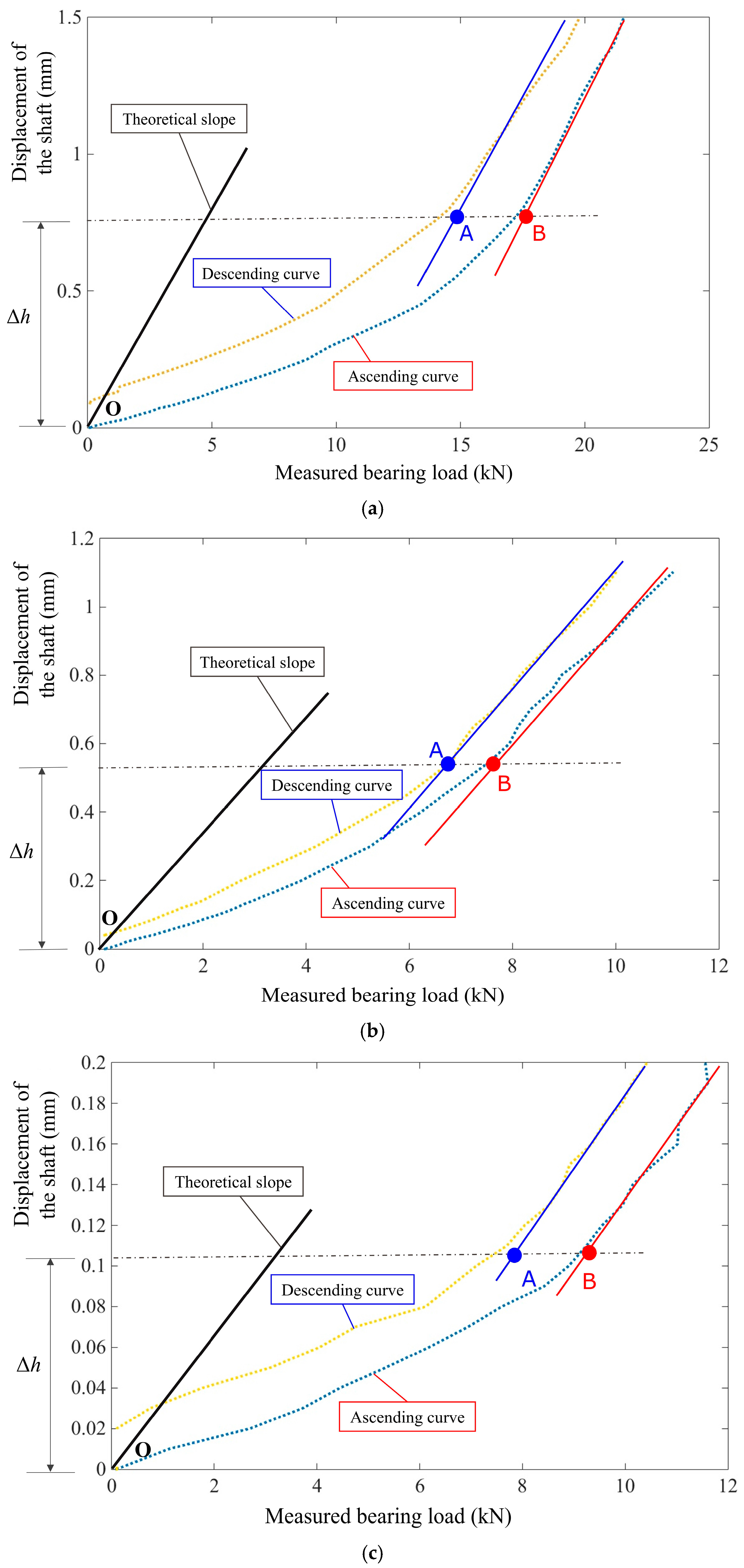
According to the standards for marine shafting alignment, the actual load of each bearing in the initial installation state was measured using the jack-up method and compared with the calculated values to validate the accuracy and credibility of the established numerical model. The specific experimental procedures of the jack-up method can be referenced in the relevant literature [8,21] and are not reiterated here. The theoretical slope was obtained by calculating the theoretical BLINs of each bearing, and the ascending and descending curves were plotted based on the measured results, as shown in Figure 3.
Within the range of Δ h , curve segment OB represents the ascent phase from the start of jacking to the state that the tested bearing is totally unloaded, while AO represents the descent phase from the first contact between the journal and the tested bearing to the state that the jack is totally unloaded. The actual measured load L b and the validity constraint of the tested bearing are:
L b = ( A + B ) / 2 s . t . ( B A ) < 0.4 L b
The trial vertical stiffness of the rear stern bearing and front stern bearing was set to 2.0 × 10⁵ N/mm and 1.7 × 10⁵ N/mm, respectively, and the lateral stiffness was set to 1.2 × 10⁵ N/mm and 1.1 × 10⁵ N/mm, respectively. For the thrust bearing, the trial vertical, lateral, and axial stiffness were set to 2.0 × 10⁵ N/mm, 1.7 × 10⁵ N/mm, and 1.2 × 10⁶ N/mm, respectively. The measured and calculated bearing load values are listed in Table 1.
Table 1 shows that the measured results are close to the calculated results. Taking the measured results as a benchmark, the calculation errors of the three bearings are 3.34%, 2.57%, and 6.70%, respectively. The small initial clearance of the thrust bearing resulted in some errors in reading and recording during the jacking process of the journal. Experimental results demonstrate that the static analysis results derived from the numerical model are valid and reliable, and can be applied to the alignment characteristics analysis of the shafting.

3. Measurement of Elastic Displacement

3.1. Elastic Displacement Increment

Excited by external loads, an elastically supported shafting will generate rigid and elastic displacement. The rigid displacement manifests as the system’s displacement relative to the global fixed coordinate system, while the elastic displacement reflects the composite elastic deformation caused by the interaction between the bearings and the supporting foundation. The vector sum of the rigid displacement and elastic displacement is the absolute displacement at a specific point within the system, and the absolute displacement difference is the relative displacement of a designated point in the system. Although the absolute displacement reflects the shafting’s displacement changes relative to the hull, it cannot accurately reflect the relative positional changes between components of the shafting, thereby making it inadequate for the elastic alignment analysis. In contrast, the relative displacement, although effectively capturing inter-component positional changes, lacks the capacity to precisely quantify system state variations induced by external environmental factors. To address positional changes and associated mechanical analysis challenges induced by elastic deformation, Zhao et al. [22] proposed the concept of elastic displacement increment (EDI) to evaluate bearing displacement, as shown in Figure 4.
The EDI uses the connecting line of any two bearings to denote the rigid displacement, and the vectorial distance from other points to this line represents their elastic deformation. Taking the rear stern bearing as an example, Figure 4a illustrates the EDI of the bearing. Figure 4b shows the EDI of any point on the supporting foundation. This method measures bearing displacement by accounting for elastic deformation of supporting foundations, yet exhibits two critical limitations:
  • The EDI may yield substantial deviation between calculated and actual displacement values when used to measure the displacement change of a certain point;
  • The EDIs at a given point under different system deformation states may be equivalent, so it cannot correctly reflect the deflection of both the shafting and its supporting foundation, as shown in Figure 4c.

3.2. Equivalent Line-Surface Method

To address the limitations mentioned above, this study proposes an equivalent line-surface method to measure the elastic deformation of the raft frame and the bearing displacement induced by it. The equivalent surface of the raft frame was obtained by the robust weighted total least squares method [23,24] to measure the elastic deformation, as illustrated in Figure 5a, and the deflection state of the centerline of the bearing housings was fitted by the polynomial fitting method [25] to measure the bearings’ displacement characteristics, as illustrated in Figure 5b.
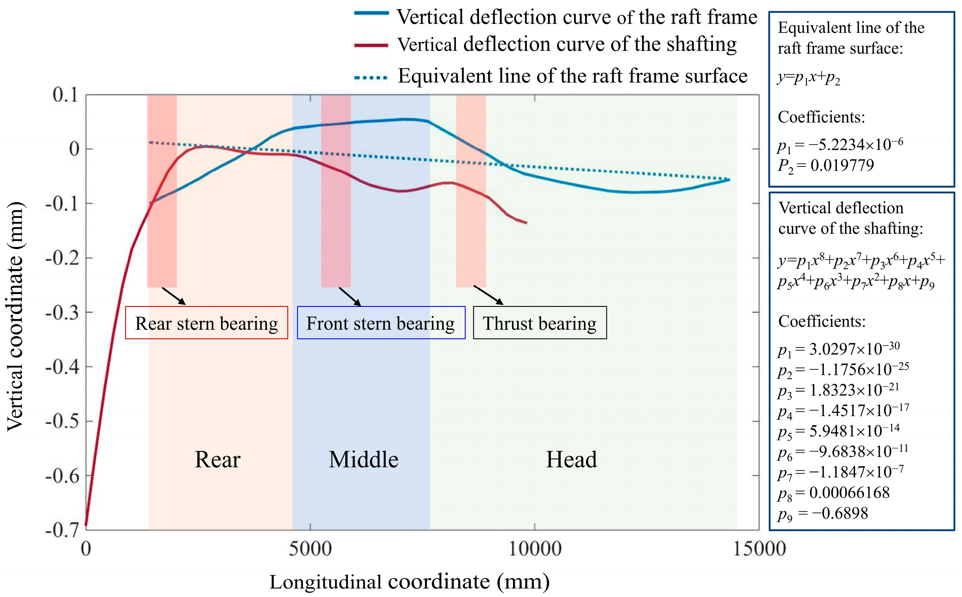
In the equivalent line-surface method, nodal coordinates on the raft frame surface are first extracted; then, the robust weighted total least squares method is used to derive the equivalent surface. The positional difference on the equivalent surface before and after displacement represents the rigid displacement of a certain node on the raft frame, and the shortest spatial distance between the nodes on the raft frame and the equivalent surface Δ y represents the elastic deformation of the raft frame, as shown in Figure 5a. Taking the centerline of the bearing housings as the reference baseline, the coordinates of each point along the line were used by the linear regression method to fit another centerline that can measure the displacement changes of the bearings, namely the equivalent line of the raft frame surface, as shown in Figure 5b. The displacement difference between a bearing and this equivalent line represents the displacement change of this bearing. This method enables the transformation of the absolute displacement obtained from finite element calculation to the displacement variations of the equivalent supporting points of the bearings, thereby obtaining the accurate elastic displacements of the bearings. In practical applications, the fitting accuracy can be enhanced by expanding the number of sample points, which ensures the measurement precision of the elastic displacement. Figure 6 shows the deflection curves of the shafting and the raft frame surface in the initial installation state, as well as the fitted equivalent line.
As shown in Figure 6, the deflection curve of the raft frame surface exhibits a shape approximating an arch, which means that the raft frame has produced significant elastic deformation. Based on the shafting’s deflection curve, the vertical displacements of the bearings Δ y j (j = 1, 2, 3) following the equivalent line-surface method can be obtained by calculating the distance between each bearing and the equivalent line. The change in reaction force of each bearing can be calculated by the following equation:
Δ F i = j = 1 3 A i j Δ y j
where Δ F i represents the reaction force change of the i-th bearing. A i j is the element in the BLINs matrix, which represents the load change of the i-th bearing induced by a unit length change in the j-th bearing’s vertical displacement [26]. However, in practice, elastic deformation will make the BLINs change dynamically.

4. Dynamic BLINs Based on Response Surface Method

For an elastically supported shafting, the coupled motion between the bearings and the raft frame causes simultaneous displacement changes of the bearings during the elastic deformation of the raft frame, leading to dynamic changes in the BLINs. In view of this problem, the response surface method was used in this study to establish the mapping relationship between the elastic displacement and the dynamic BLINs, aiming to achieve alignment optimization of the elastically supported submarine propulsion shafting.

4.1. BLINs Considering Elastic Deformation

Based on the concept of BLINs [8,27], in the initial installation state, considering the supporting foundation as rigid (fixed without deformation) and elastic (supported by elastic boundary conditions), respectively, the rigid BLINs matrix A r and the elastic BLINs matrix A e were calculated (unit: kN/mm).
A r = 0.59 1.56 1.85 1.56 5.79 6.78 1.85 5.67 27.65
A e = 0.64 1.16 1.22 1.16 6.76 10.65 0.78 3.71 37.75
By comparing Equations (3) and (4), it is evident that A r is a symmetric matrix, whereas A e is an asymmetric matrix. This asymmetry arises from the dynamic changes in the vertical positions of all the three bearings caused by the elastic deformation of the raft frame. Compared to rigid support, considering the elasticity of the support foundation leads to an increase in the BLICs of all the bearings relative to their own positions, especially for the thrust bearing. When the shafting is elastically supported, the load of the thrust bearing increases by 37.75 kN for every 1 mm of elevation, which is significantly higher than 27.65 kN under rigid conditions. Moreover, when the front stern bearing is raised by 1 mm, the loads of both the rear stern bearing and thrust bearing decrease, which is obviously distinct from rigid support.
Defining the vertical position of a bearing as the height relative to the equivalent line of the raft frame surface, the BLINs matrix A e in the initial installation state was calculated, as shown in Equation (5).
A e = 0.45 1.77 2.05 1.80 4.66 6.13 2.00 5.98 18.92
The raft frame will achieve a so-called leveled state when the deflection curve of the raft frame surface is approximately a horizontal straight line, after regulation of the airbag vibration isolators’ pressure. The calculated BLINs matrix A e in the leveled state is shown in Equation (6).
A e = 0.87 0.94 3.16 0.99 2.72 5.58 3.04 5.39 22.92
Comparing Equations (5) and (6) with (4), it can be seen that measuring the position of each bearing using the equivalent line of the raft frame surface can effectively reduce the influence of elastic deformation on the asymmetry of the BLINs matrix, but the BLINs will change dynamically according to the deformation state of the raft frame surface.

4.2. Response Surface Method Using GPR

To calculate the dynamic BLINs of each bearing with different combinations of vertical displacements, the response surface method based on GPR [28,29] was used to establish the mapping relationship between the elastic displacement and the dynamic BLINs.
The training sample set L for the response surfaces is:
L = ( x i , y i ) i = 1 , 2 , 3 , , n = ( X , y )
where y is the output vector of training, which refers to the BLINs; x i X are the input variables, X = Δ y 1 , Δ y 2 , Δ y 3 T . Δ y 1 , Δ y 2 , and Δ y 3 are the equivalent vertical displacements of the three bearings. The mean function and covariance function of the response surfaces are denoted as u(x) and r ( x , x ) , respectively, and the Gaussian process can be expressed as:
y G P ( u ( x ) , r ( x , x ) )
During the training process, u(x) was considered as zero, and the squared exponential covariance function was used for training, which can be expressed as:
r S E ( x i , x j ) = σ f 2 exp ( 1 2 l 2 x i x j 2 ) + σ n 2 δ ij
where x i and x j are the input vectors of the training sample set; and l is the local correlation parameter, which takes values within [0, 1] and indicates the data correlation between two sample points. During the process of GPR, better local correlation parameters can be adaptively obtained through error analysis and iterative optimization. σ f = 0.5 is the local correlation control parameter; ε N ( 0 , σ n 2 ) represents the random data error during training process and σ n represents its standard deviation; δ ij is the Kronecker delta.
Use the numerical model of the shafting to generate sample points. For the i-th sample point, x i and y j can be written as:
x i = Δ y 1 i ,   Δ y 2 i ,   Δ y 3 i T
y i = Δ F 11 i Δ F 12 i Δ F 13 i Δ F 21 i Δ F 22 i Δ F 23 i Δ F 31 i Δ F 32 i Δ F 33 i
where Δ F j k i (j, k = 1, 2, 3) are the elements of the BLINs matrix of the i-th sample point. With the zero-mean constraint of the output vector y imposed, according to Equation (8), the covariance matrix R ( X ,   X ) can be written as:
y N ( 0 ,   R ( X ,   X ) )
R ( X ,   X ) = r ( x 1 ,   x 1 ) r ( x 1 ,   x 2 ) r ( x 1 ,   x n ) r ( x 2 ,   x 1 ) r ( x 2 ,   x 2 ) r ( x 2 ,   x n ) r ( x n ,   x 1 ) r ( x n ,   x 2 ) r ( x n ,   x n )
The following relations are defined:
R [ X * ,   X ] = r ( x * ,   x 1 ) r ( x * ,   x 2 ) r ( x * ,   x n )
R [ X * ,   X * ] = r ( x * ,   x * )
The output vector y and the regression-predicted vector y * then follow the joint distribution:
y y * N 0 ,   R ( X ,   X ) + σ n 2 E R ( X * ,   X ) T R ( X * ,   X ) R ( X * ,   X * )
where E represents the identity matrix. According to Equation (16), the mean function and variance of the output vector y are predicted; thus, the response surfaces of the BLINs corresponding to the training set L can be built. The whole process is shown in Figure 7, including the following steps:
  • Randomly sample within the feasible ranges of the bearings’ equivalent displacement using the Latin hypercube sampling method, and generate the initial training sample set via the numerical model of the shafting.
  • Use the GPR to train the regression equation, and test the accuracy of the training model with newly generated sample points. The test method is used to calculate the average relative error of each bearing load, with the requirement that the load error of the stern bearings should not exceed 5%, while that of the thrust bearing should not exceed 1%.
  • If the accuracy of the training model is not satisfied, the newly generated sample points will be aggregated into the training set to improve the training quality.
  • When the training accuracy meets the requirements, the local sample points at the feasible region boundary will be predicted and compared with the numerical calculation results. If the errors are unacceptable, the process will return to Step (3). When the errors are acceptable, the GPR response surfaces will be output.

5. Alignment Optimization

5.1. Response Surfaces of the Dynamic BLINs

When the raft frame is in the leveled state mentioned above, the alignment calculation can be considered as the straight-line alignment calculation taking the raft frame as benchmark. Based on the numerical model of the elastically supported shafting, the alignment in such condition was calculated, and the results are shown in Table 2.
Due to the cantilever effect induced by the heavy propeller, the load of the rear stern bearing is very large, as listed in Table 2. Vertical displacement ranges of [−3.5, 3.5] mm for both the rear and front stern bearings, and [−2, 2] mm for the thrust bearing were selected to build the response surfaces between vertical displacements and the BLINs, following the measurement criterion of the equivalent line-surface method. Since the vector with dimension greater than four is a hypercube in spatial coordinates, the built response surfaces are presented in three-dimensional form below.
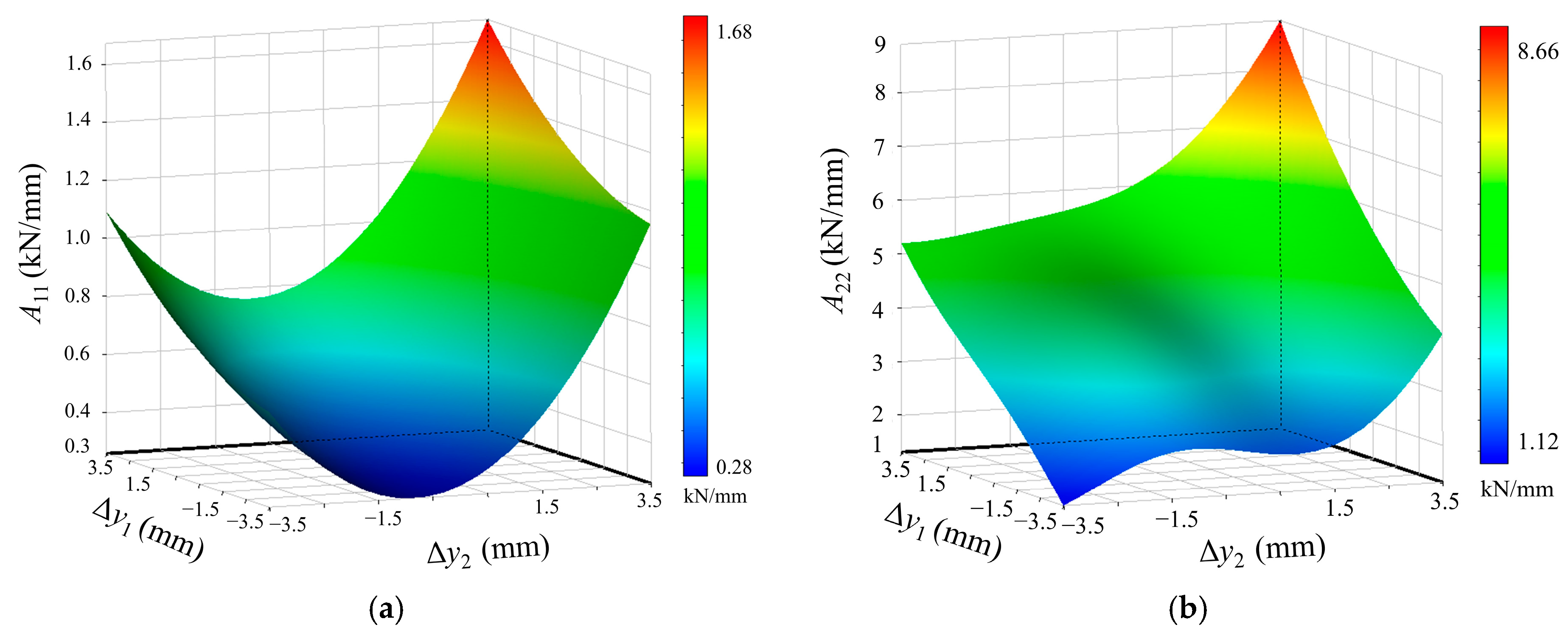
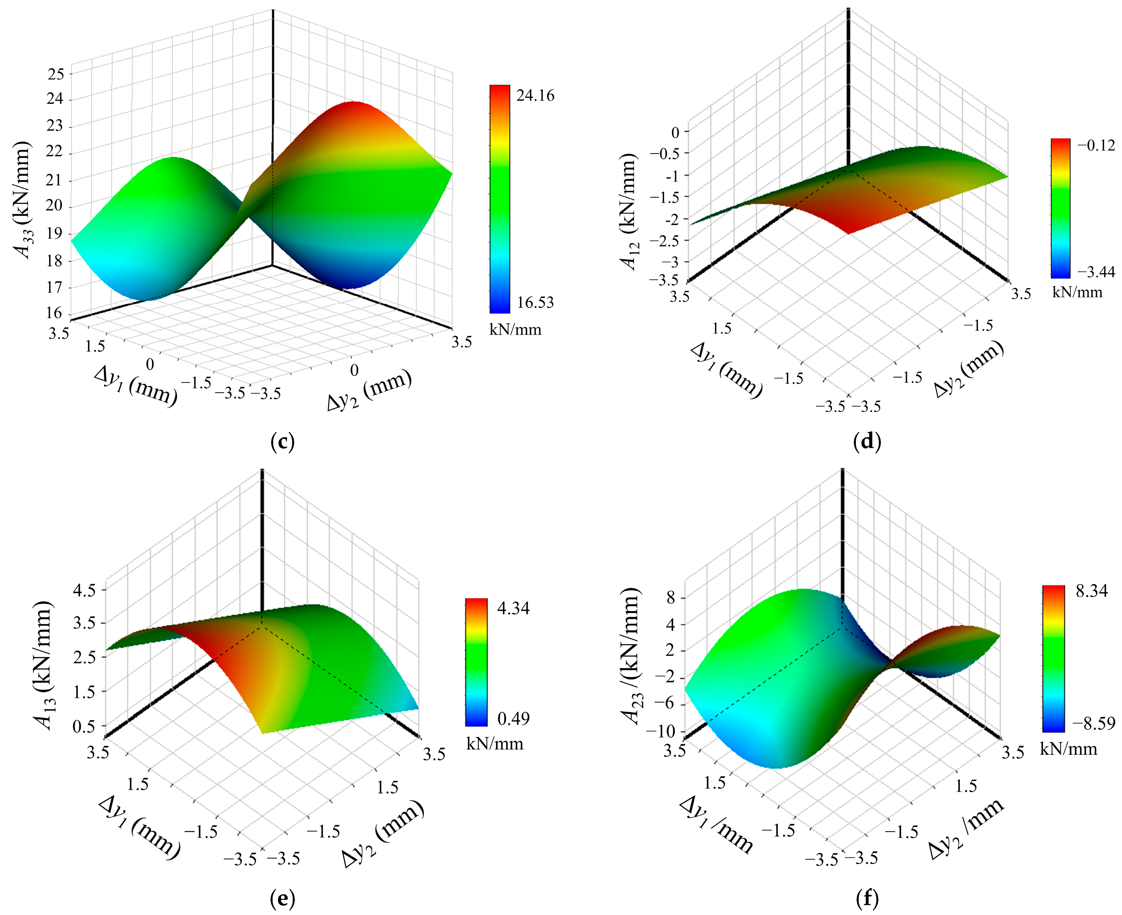
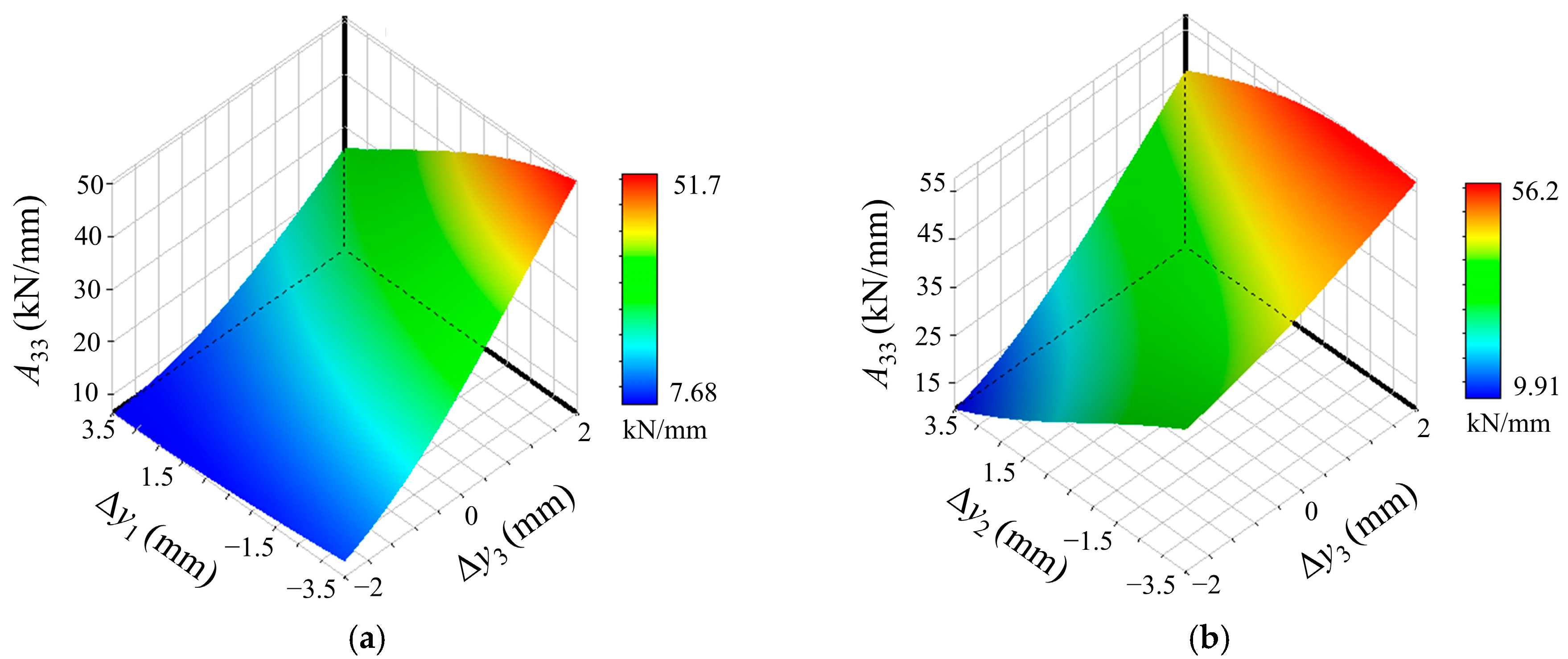
Figure 8 shows the response surfaces between each element in the BLINs matrix and the vertical displacement of the rear stern bearing Δ y 1 and the front stern bearing Δ y 2 . It can be seen that the BLINs change dynamically with the variation of Δ y 1 and Δ y 2 . As shown in Figure 8a, when the height of the front stern bearing is fixed, the influence number of the rear stern bearing about itself A 11 increases approximately linearly with the elevation of itself. However, when the height of the rear stern bearing is fixed, A 11 initially decreases and then increases with the elevation of the front stern bearing. In Figure 8b, the influence number of the front stern bearing about itself A 22 is positively correlated with the displacements of two stern bearings. When Δ y 1 and Δ y 2 are more than 3 mm, A 22 begins to rise rapidly. In Figure 8c, the influence number of the thrust bearing about itself A 33 has a nonlinear relationship with the variation of Δ y 1 and Δ y 2 . A 33 initially decreases and then increases with the increase in Δ y 1 , but first increases and then decreases with the increase in Δ y 2 . Combined with the analysis results of the bearing displacement characteristics and the deflection of the raft frame, with the heights of the stern bearings within certain ranges, the shafting is approximately in the straight-line alignment state. The load among the bearings is evenly distributed, and the change in bearing load caused by elastic deformation is mainly concentrated on the rear stern bearing. When the adjacent bearings are continuously elevated or lowered, the raft frame will generate obvious middle arching or subsiding deformation, and the displacement of the thrust bearing Is apparent, to some extent, which will seriously deteriorate its working condition and even cause the bearing to become locked or void. The BLINs of the thrust bearing will significantly increase or decrease, too.
Figure 8d–f show the response surfaces between A 12 , A 13 , A 23 and Δ y 1 , Δ y 2 . It can be seen that there is a weak coupling between the load of the rear stern bearing and the front stern bearing. When Δ y 1 or Δ y 2 is individually adjusted, A 12 exhibits minimal variation characterized by an approximately linear trend. It can be found from Figure 8e,f that the load characteristics between the stern bearings and the thrust bearing are highly coupled. The displacements of the stern bearings, especially for the front stern bearing, significantly influence the load of the thrust bearing, making the BLINs transit from positive to negative within a small displacement range. Therefore, the variation law of the influence number of the thrust bearing about itself A 33 was further analyzed, as shown in Figure 9.
According to Figure 9a, when Δ y 3 = −2 mm, A 33 changes linearly with Δ y 1 . With the increase in Δ y 3 , the decreasing amplitude of A 33 with the elevation of the rear stern bearing increases significantly, indicating an obvious positive coupling between Δ y 1 , Δ y 3 and the load of the thrust bearing. According to Figure 9b, when Δ y 3 = −2 mm, A 33 decreases significantly with the increase in Δ y 2 . With the increase in Δ y 3 , the decreasing amplitude of A 33 with the elevation of the front stern bearing decreases significantly, indicating an obvious negative coupling between Δ y 2 , Δ y 3 and the load of the thrust bearing. With the variation in Δ y 2 and Δ y 3 , the maximum value of A 33 is 56.2 kN/mm, suggesting that the amplification effect of the coupling of Δ y 2 and Δ y 3 on A 33 is bigger than that of Δ y 2 alone. The displacement of the front stern bearing will lead to an obvious load change of the thrust bearing.
From the analysis above, it can be seen that the BLINs of the thrust bearing demonstrate high sensitivity to the displacement of each bearing. The displacement of the thrust bearing has a strong nonlinear relationship with the displacements of the stern bearings. Therefore, during alignment optimization, it is necessary to focus on the load of the thrust bearing and avoid large displacement of the thrust bearing to avert safety threats caused by uneven load distribution among the bearings.
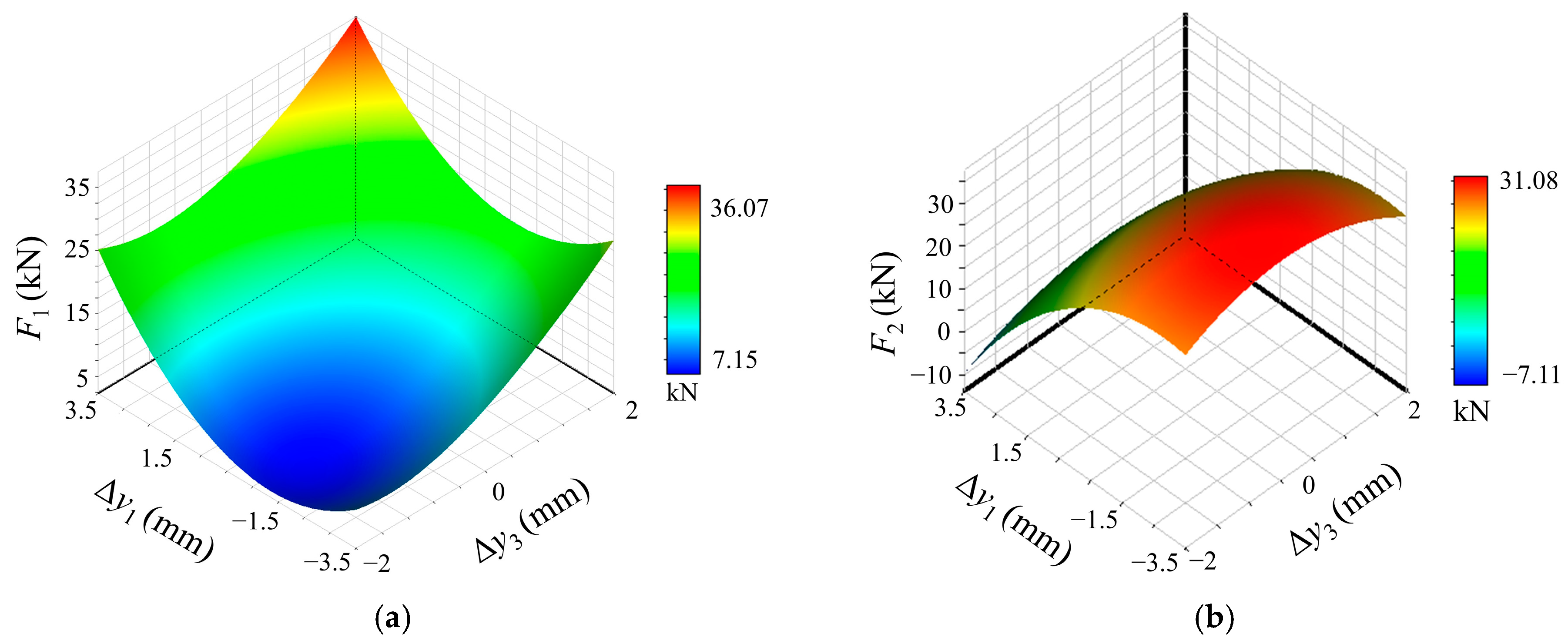
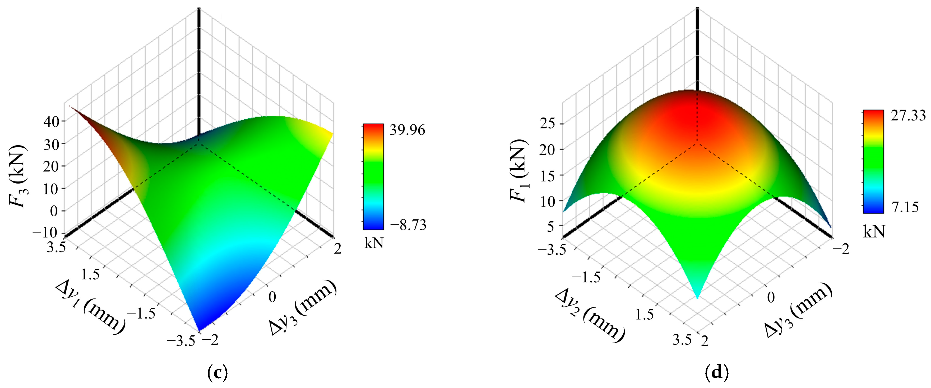
In order to intuitively reflect the relationship between bearing loads and bearing displacements, some of the response surfaces between bearing reaction forces and bearing displacements are shown in Figure 10.
In Figure 10a–c, when Δ y 3 is a constant value, the reaction force of the rear stern bearing F 1 initially decreases and then increases with the elevation of the rear stern bearing. When Δ y 1 ∈ [−3.5, 0] mm, Δ y 3 ∈ [−2, 0] mm, the load is mainly on the front stern bearing. When the vertical position of the rear stern bearing is elevated, due to the large load influence numbers of the thrust bearing, the load of the rear stern bearing initially decreases and then increases. Meanwhile, the load of the front stern bearing decreases and that of the thrust bearing increases. When Δ y 1 ∈ [0, 3.5] mm and Δ y 3 ∈ [0, 2] mm, elevating the rear stern bearing and the thrust bearing will increase the load of themselves, but reduce the load of the front stern bearing. When Δ y 3 = 2 mm, the load of the thrust bearing increases initially and then decreases with the elevation of the rear stern bearing. This is because when Δ y 1 ∈ [0, 2] mm, the raft frame is still middle arched, and enlarging Δ y 1 will significantly reduce the load of the front stern bearing. The load reduction in the thrust bearing caused by elastic deformation is less than the load increase caused by the BLINs, making the load of the thrust bearing increase initially and then decrease.
From Figure 10d, it can be seen that excessive vertical displacements of both the front stern bearing and thrust bearing will reduce the load of the rear stern bearing. There is a stable area in the response surfaces of the load of the rear stern bearing and Δ y 2 , Δ y 3 , which means, in the feasible region of Δ y 2 ∈ [−1.5, 1.5] mm and Δ y 3 ∈ [−1, 1] mm, the rear stern bearing load tends to be stable, and the displacements of two stern bearings do not have a great impact on it.
Taking the results of the straight-line alignment calculation and the response surface analysis above into conclusion, two critical issues of the alignment of the elastically supported shafting are revealed:
  • The load of the rear stern bearing is too large, and prolonged operation under this condition may lead to abnormal wear of the stern shaft segments and bearings, compromising the safety and stability of the shafting.
  • The BLINs of the thrust bearing is much larger than that of the stern bearings, so, influenced by elastic deformation, vertical displacement of the thrust bearing will greatly change its load. Therefore, even-load distribution of the bearings should be taken into account to avert the instability of the thrust bearing caused by excessive displacement during the process of alignment optimization.

5.2. Alignment Optimization Based on GPR Response Surfaces

In view of the problems above, aiming at reducing the load of the rear stern bearing and improving the evenness of load distribution among bearings, the alignment optimization of the elastically supported submarine propulsion shafting was carried out based on the GPR response surfaces. First of all, the heights of the thirteen supporting points illustrated in Figure 2 were derived via numerical calculation, and the single equivalent supporting point of each bearing was obtained using the shear balance equation. The vertical displacements of the three bearings’ supporting points Δ y j (j = 1, 2, 3) under the equivalent line-surface method were selected as the optimization variables ( Δ y 1 ∈ [−3.5, 3.5] mm, Δ y 2 ∈ [−3.5, 3.5] mm, and Δ y 3 ∈ [−1, 1] mm). The reaction force of each bearing F i can be expressed as:
F i = F 0 i + j = 1 3 A i j Δ y j ,   i = 1 ,   2 ,   3
where F 0 i represents the reaction force of the i-th bearing in the straight-line alignment state and A i j represents the bearing load influence number output by the response surface. The optimization objective function was defined as:
min φ 1 = F 1 φ 2 = 1 3 i = 1 3 ( F i F ¯ ) 2
where φ 1 represents the load index of the rear stern bearing; φ 2 represents the evenness index expressed by the standard deviation of the loads of the three bearings; and F ¯ is the average load value of the three bearings. In order to satisfy the alignment requirements of marine propulsion shafting, the constraints during the optimization were defined as:
s . t .   0.2 G i F i F i max ϕ n [ ϕ ] σ max [ σ ]
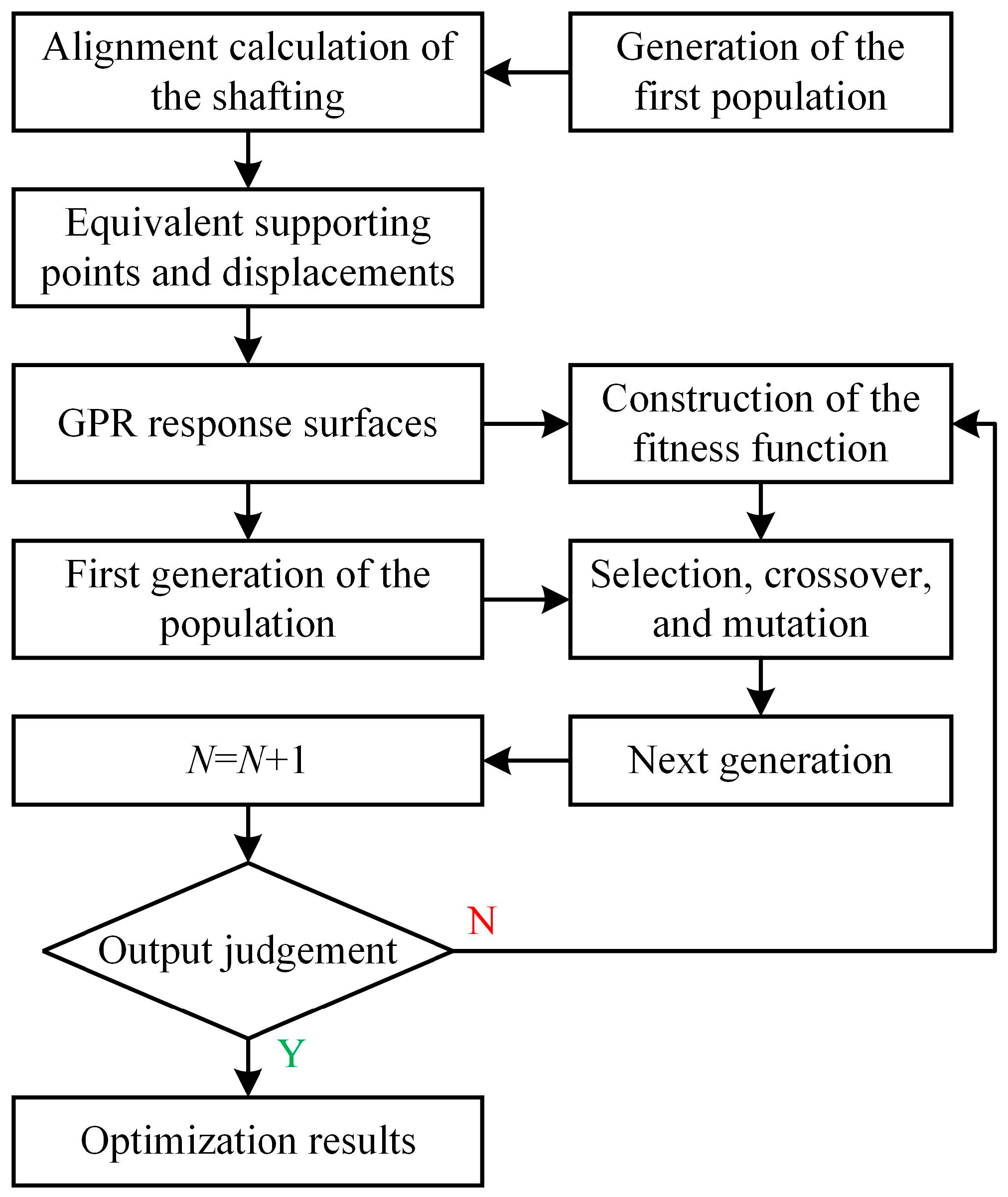
where F i max is the maximum allowable reaction force for the i-th bearing and G i is the total weight of the two adjacent shaft segments that the i-th bearing spans; ϕ n is the maximum rotation angle at the connection of the n-th shaft segment and [ ϕ ] is the maximum allowable value; σ max is the maximum stress of all the shaft segments; and [ σ ] is the maximum allowable value. Combined with the built GPR response surfaces, the genetic algorithm [24] was used to realize the alignment optimization of the elastically supported shafting, and the optimization process is shown in Figure 11.
In Figure 11, N is the genetic generation number in the algorithm. In the value ranges of Δ y j , 103 points were sampled randomly, and the mapping relationship between Δ y j and the BLINs was obtained by the response surface method. The fitness function of the genetic algorithm was constructed according to Equation (9), which can be written as:
η ( x ) = 1 σ f 2 exp ( 1 2 l 2 Δ y i Δ y j 2 ) + σ n 2 δ i j
The maximum generation number of the genetic algorithm was set to 300, and the crossover probability and mutation probability were set to 0.9 and 0.01, respectively. The final optimization results will be output when the iteration number exceeds the maximum generation number, or the optimization results satisfy the convergence error. The final optimization results are shown in Table 3.
Compared with the data in Table 2, after optimization, the load of the rear stern bearing was reduced by 2.99 kN, and the load difference between the front and rear stern bearings was reduced by 4.98 kN. Due to the small value of Δ y 3 , the load of the thrust bearing was basically unchanged. The standard deviation of the loads of the three bearings was reduced from 4.84 to 3.04, making the load distribution more reasonable. Therefore, the working state of the shafting was improved. In addition, the rotation angle of each bearing was reduced; thus, the deflection angles of the journals were reduced, too, which is more beneficial to the safe and stable operation of the shafting.

6. Conclusions

In this study, an alignment calculation model for the elastically supported propulsion shafting of a submarine was established, and its applicability was validated experimentally. A systematic and scientific calculation method for the dynamic BLINs was studied and acquired. Based on the dynamic BLINs, the alignment of the elastically supported shafting was optimized. The main conclusions are summarized as follows:
  • To address the measurement challenges of elastic deformation in elastically supported shafting, an equivalent line-surface method was proposed to measure the elastic bearing displacement, and the concept of the dynamic BLINs was elicited considering elastic deformation.
  • Using the GPR response surfaces, the mapping relationship between the elastic displacement and the dynamic BLINs was established, and the dynamic BLINs caused by elastic deformation were acquired.
  • According to the analysis results of the straight-line alignment and the response surfaces, the optimization objective functions were defined and the genetic algorithm was used for alignment optimization. After optimization, the load of the rear stern bearing and the load difference between two stern bearings were reduced. The load distribution among the bearings became more even.
The studied results can provide theoretical and technical support for the alignment optimization of elastically supported marine propulsion shafting, including the measurement of elastic deformation and the calculation of the elastic bearing displacement. However, there are also some limitations in this study. The numerical model incorporates some simplifications, and the external dynamic excitation is excluded in the alignment calculation, consequently leading to discrepancies between the simulation environment and actual working environment. Subsequent research will focus on establishing an alignment calculation model that more accurately reflects the operational characteristics of elastically supported shafting, with refinement to be implemented through experimental data from actual objects, to enhance the engineering applicability of the proposed methods. Furthermore, it is necessary to investigate applicable dynamic surrogate models incorporating adaptive sampling strategies to minimize the computational expense of both the elastic displacement measurement method and the response surface method while ensuring fitting accuracy.

Author Contributions

Conceptualization, J.L. and Z.G.; methodology, J.L.; validation, Z.G. and J.H.; formal analysis, J.L. and Z.G.; investigation, J.L. and Z.G.; resources, J.L.; data curation, J.L.; writing—original draft preparation, J.L. and Z.G.; writing—review and editing, Z.G., J.H. and S.C.; visualization, J.L. and Z.G.; supervision, J.L. and S.C.; project administration, Z.G. and J.H.; funding acquisition, J.L. All authors have read and agreed to the published version of the manuscript.

Funding

This research was funded by the National Defense Science and Technology Project, grant number 2023-04527.

Institutional Review Board Statement

Not applicable.

Informed Consent Statement

Not applicable.

Data Availability Statement

Data available on reasonable request due to privacy restrictions.

Conflicts of Interest

The authors declare no conflicts of interest.

References

  1. Chen, G.; Zeng, F. Modern Marine Engineering, 1st ed.; National University of Defense Science and Technology Press: Changsha, China, 2001; pp. 545–546. ISBN 7-81024-734-4. [Google Scholar]
  2. Zhang, Y.; Xu, W.; Li, Z.; Yin, L. Alignment and safety analysis of marine propulsion shafting using intelligent raft system. J. Mar. Sci. Technol. 2021, 26, 323–330. [Google Scholar] [CrossRef]
  3. Sharma, S.K.; Sharma, R.C.; Lee, J. Modelling and simulation of MR damper characterization and uncertainty assessment in marine engine vibration isolation with FLPID control. Int. J. Model. Simul. 2024, 1–11. [Google Scholar] [CrossRef]
  4. Liu, S.; Shi, L.; Xu, W.; Hu, Z. Digital-twin driven alignment control method for marine shafting with air spring vibration isolation system. Sci. Rep. 2025, 15, 1065. [Google Scholar] [CrossRef]
  5. Deliporanides, G. Finite element shaft alignment on elastic foundation. Int. Shipbuild. Prog. 1992, 39, 391–397. [Google Scholar] [CrossRef]
  6. Murawski, L. Shaft line alignment analysis taking ship construction flexibility and deformations into consideration. Mar. Struct. 2005, 18, 62–84. [Google Scholar] [CrossRef]
  7. Murawski, L. The influence of shaft line alignment accuracy on the operational reliability of marine propulsion systems. J. KONES 2016, 23, 247–254. [Google Scholar] [CrossRef]
  8. Zhou, R. The Theoretic Studies on the Propulsion Shafting Alignment of Ultra-Large Vessels. Ph.D. Thesis, Wuhan University of Technology, Wuhan, China, 2005. [Google Scholar]
  9. Khalyavkin, A.A.; Makeev, S.A.; Loshadkin, D.V.; Mamontov, V.A.; Auslender, A.Y. Analysis of influence of elastic properties of deadwood bearings on shaft line operability. Vestn. Astrakhan State Tech. Univ. Ser. Mar. Eng. Technol. 2021, 2, 7–15. [Google Scholar] [CrossRef]
  10. Gu, Z.; Fu, Y.; Li, Z.; Yang, P. Shafting alignment calculation of large span propeller shafts. J. Ship. Mech. 2024, 28, 435–441. [Google Scholar] [CrossRef]
  11. Murawski, L. Thermal interaction between main engine body and ship hull. Ocean Eng. 2018, 147, 107–120. [Google Scholar] [CrossRef]
  12. Seo, C.O.; Jeong, B.U.; Kim, J.R.; Song, M.H.; Noh, J.H.; Lee, J.U. Determining the influence of ship hull deformation caused by draught change on shaft alignment application using FE analysis. Ocean Eng. 2020, 210, 107488. [Google Scholar] [CrossRef]
  13. Avgouleas, K.; Sarris, E.; Gougoulidis, G. Practical Aspects of Propulsion Shaft Alignment. In Proceedings of the 7th International Symposium on Ship Operations, Management & Economics, Athens, Greece, 6–7 April 2021. [Google Scholar] [CrossRef]
  14. Chen, Z.; Wang, J.; Li, R.; Liu, Y. A novel 4-DOF marine stern bearing support model considering discrete distribution effects. Ocean Eng. 2024, 312, 119072. [Google Scholar] [CrossRef]
  15. Nickabadi, S.; Hosseini, S.M.; Bathaee, H.; Alirezaeipour, S. Marine shaft optimization using surrogate models and multi-objective optimization. Structures 2024, 63, 106415. [Google Scholar] [CrossRef]
  16. Magalhães, D.L.; Martins, D.H.C.S.S.; Castro, B.M.; Vaz, L.A.; Monteiro, U.A.; Gutiérrez, R.H.R. Machine learning performance comparison for main propulsive shafting systems alignment. Ocean Eng. 2023, 280, 114556. [Google Scholar] [CrossRef]
  17. Lai, G.; Lei, J.; Liu, J.; Cao, S.; Qin, H.; Zeng, F.; Zhou, R. Numerical and experimental study on comprehensive optimization for the KPIs of ship propulsion shafting design based on MDO. Ocean Eng. 2021, 222, 108624. [Google Scholar] [CrossRef]
  18. Li, R.; Wang, J.; Chen, Z.; Wang, F.; Liu, Y. Study on the Methods of Measurement, Optimization and Forecast of Propulsion Shaft Bearing Load of Ships. J. Mar. Sci. Eng. 2023, 11, 1324. [Google Scholar] [CrossRef]
  19. Bsiso, R.M.; Ripin, Z.M. Optimizing the bearing vertical offset of a marine propeller shaft system. Proc. IMechE Part M J. Eng. Mar. Environ. 2024, 14750902241277260. [Google Scholar] [CrossRef]
  20. Sun, J.S.; Kim, Y.G.; Kim, U.K. Study on shaft alignment of propulsion shafting system depending on single reaction force supporting position of aft stern tube bearing. J. Mar. Sci. Technol. 2021, 26, 1340–1357. [Google Scholar] [CrossRef]
  21. Zhou, R.; Xu, L.; Zhang, S.; Huang, Z. Study on some technical problems in alignment of ship propulsion shafting. Ship. Eng. 2004, 26, 48–52. [Google Scholar] [CrossRef]
  22. Zhao, X.; Shuai, C.; Xu, W.; Li, Z. Research on bearings load-increment in integrated vibration isolation system of ship stern. Eng. Mech. 2019, 36, 311–315. [Google Scholar] [CrossRef]
  23. Schaffrin, B.; Lee, I.; Choi, Y.; Felus, Y. Total Least-Squares (TLS) for geodetic straight-line and plane adjustment. Boll. Geod. Sci. Affini 2006, 65, 141–168. [Google Scholar]
  24. Liu, Z.; Li, M.; Lu, J. Cylindrical Fitting of Point Cloud Data Based on Robust Weighted Total Least Squares. Mod. Surv. Mapp. 2018, 41, 39–42. [Google Scholar] [CrossRef]
  25. Sebastian, T.B.; Klein, P.N.; Kimia, B.B. On aligning curves. IEEE Trans. Pattern. Anal. Mach. Intell. 2003, 25, 116–125. [Google Scholar] [CrossRef]
  26. Liu, J.; Gu, Z.; Liu, S. Research on MDO of ship propulsion shafting dynamics considering the coupling effect of a propeller-shafting-hull system. Pol. Marit. Res. 2023, 30, 86–97. [Google Scholar] [CrossRef]
  27. Lu, L.; Li, G.; Xing, P.; Gao, L.; Song, Y.; Zhang, H. Numerical calculation and experimental investigation of the dynamic alignment of ship propulsion shafting based on Latin hypercube stochastic finite element. Ocean Eng. 2024, 296, 116935. [Google Scholar] [CrossRef]
  28. Nguyen, A.H.; Rath, M.; Leitinger, E.; Nguyen, K.V.; Witrisal, K. Gaussian Process Modeling of Specular Multipath Components. Appl. Sci. 2020, 10, 5216. [Google Scholar] [CrossRef]
  29. Singf, S.K.; Mali, H.S.; Unune, D.R.; Wojciechowski, S.; Wilczyński, D. Application of Generalized Regression Neural Network and Gaussian Process Regression for Modelling Hybrid Micro-Electric Discharge Machining: A Comparative Study. Processes 2022, 10, 755. [Google Scholar] [CrossRef]
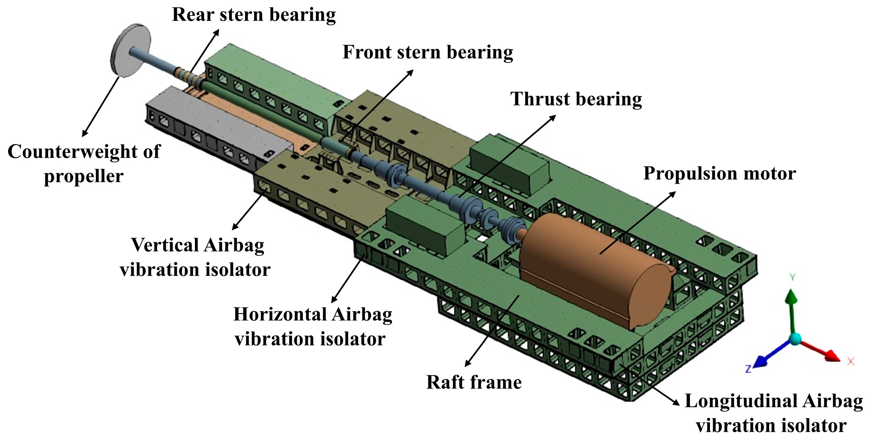
Figure 1. Layout diagram of an elastically supported submarine propulsion shafting.
Applsci 15 04348 g001
Figure 2. Numerical model of the shafting.
Applsci 15 04348 g002
Figure 3. Jacking curves. (a) Rear stern bearing; (b) front stern bearing; (c) thrust bearing.
Applsci 15 04348 g003
Figure 4. Schematic diagram of the EDI. (a) EDI of the rear stern bearing ( Δ 1 ); (b) EDI of any point on the supporting foundation ( Δ x ); (c) EDIs under different deformation states are equivalent.
Applsci 15 04348 g004
Figure 5. Equivalent line-surface method. (a) Equivalent surface; (b) equivalent line.
Applsci 15 04348 g005
Figure 6. Deflection curves and equivalent line.
Applsci 15 04348 g006
Figure 7. Flowchart for building the response surfaces using GPR.
Applsci 15 04348 g007
Figure 8. Response surfaces between the BLINs and Δ y 1 , Δ y 2 . (a) A 11 _ Δ y 1 _ Δ y 2 ; (b) A 22 _ Δ y 1 _ Δ y 2 ; (c) A 33 _ Δ y 1 _ Δ y 2 ; (d) A 12 _ Δ y 1 _ Δ y 2 ; (e) A 13 _ Δ y 1 _ Δ y 2 ; (f) A 23 _ Δ y 1 _ Δ y 2 .
Applsci 15 04348 g008aApplsci 15 04348 g008b
Figure 9. Response surfaces of A 33 . (a) A 33 _ Δ y 1 _ Δ y 3 ; (b) A 33 _ Δ y 2 _ Δ y 3 .
Applsci 15 04348 g009
Figure 10. Response surfaces of bearing reaction forces. (a) F 1 _ Δ y 1 _ Δ y 3 ; (b) F 2 _ Δ y 1 _ Δ y 3 ; (c) F 3 _ Δ y 1 _ Δ y 3 ; (d) F 1 _ Δ y 2 _ Δ y 2 .
Applsci 15 04348 g010aApplsci 15 04348 g010b
Figure 11. Alignment optimization process of the elastically supported shafting.
Applsci 15 04348 g011
Table 1. Measured and calculated load of each bearing (unit: kN).
BearingABMeasured LoadCalculated LoadB − A
Rear stern bearing14.8917.4116.1516.692.52
Front stern bearing6.827.927.377.181.10
Thrust bearing7.839.798.818.221.96
Table 2. Calculation results of straight-line alignment taking the raft frame as benchmark.
BearingRelative Deflection (mm)Bearing Load (kN)Rotation Angle (Rad)
Rear stern bearing0.19817.949.79 × 10−4
Front stern bearing−0.0767.14−3.31 × 10⁻⁴
Thrust bearing−0.0958.31−2.54 × 10⁻⁴
Table 3. Alignment optimization results of the elastically supported shafting.
Bearing Δ y i (mm)Bearing Load (kN)Rotation Angle (Rad)
Rear stern bearing−0.5714.957.86 × 10−4
Front stern bearing0.149.15−3.25 × 10⁻⁴
Thrust bearing0.058.012.27 × 10−4
Disclaimer/Publisher’s Note: The statements, opinions and data contained in all publications are solely those of the individual author(s) and contributor(s) and not of MDPI and/or the editor(s). MDPI and/or the editor(s) disclaim responsibility for any injury to people or property resulting from any ideas, methods, instructions or products referred to in the content.