Abstract
This study conducts a comparative performance analysis of three different low-temperature solar collector systems: flat plate solar collectors (FPCs), heat pipe evacuated tube solar collectors (HPETCs), and heat pipe flat plate solar collectors (HPFPCs). Key performance parameters, such as heat transfer coefficients, useful heat, and thermal efficiency, are analyzed under varying mass flow rate, fluid temperature, and antifreeze concentration. The objective is to evaluate the thermal performance of these systems using different heat transfer fluids, specifically water, and mixtures of 30% and 50% ethylene glycol and propylene glycol. The performance data indicate that the heat transfer coefficient in the HPFPC diminishes by 28% and 41% when antifreeze is employed at concentrations of 30% and 50%, respectively. Furthermore, the integration of heat pipes with water in a flat plate solar collector results in efficiency enhancements, with respect to FPCs, of up to 13% at a fluid temperature of 30 °C, and up to 21% at 80 °C. At the elevated fluid temperature of 80 °C, an efficiency increase of 13% is observed with a 30% ethylene glycol concentration. The incorporation of heat pipes leads to an efficiency improvement of up to 6.5% in comparison to traditional flat plate solar collectors. This study highlights the significant impact of fluid properties, affecting the convective heat transfer coefficient, on the overall efficiency of solar collectors, emphasizing the importance of optimizing fluid composition and operating conditions for enhanced thermal performance.
1. Introduction
According to the National Aeronautics and Space Administration (NASA), there is clear and indisputable evidence that the Earth is experiencing rapid warming, primarily driven by human activities [1]. In an effort to change this situation, the aim is to use energy sources that are not harmful to the environment. Many studies report the use of various types of renewable energy to meet different needs, whether in the residential, commercial, industrial, or transportation sectors [2,3]. Today, solar energy is extensively utilized across various sectors, both for generating power and for general heating and cooling systems, as reported in different reviews [4,5,6]. Ramachandran et al. [4] show that solar energy projects have proliferated across the UAE, demonstrating a diverse range of applications from residential systems to large-scale power plants, resulting in reduced fossil fuel use and greenhouse gas emissions. The study by Pascaris et al. [5] examines the integration of agrivoltaic systems, which combine agricultural production and solar energy, highlighting their technical and economic viability, the importance of social acceptance, and the opportunities they present for developing policies that promote sustainable land use. In [6], solar energy technologies, emphasizing their potential in meeting future energy demands are examined by Kabir et al. They state that large-scale solar power systems significantly contribute to energy generation while mitigating carbon emissions, and that challenges such as land requirements, intermittency, and fluctuating policy support delay growth.
Generally, low-temperature solar collectors are used for various applications [7,8,9] including the following:
- -
- Water heating: used in homes and buildings to heat water for domestic and commercial use, especially in areas with sufficient solar radiation.
- -
- Space heating: they can be integrated into heating systems in buildings, providing supplemental heat.
- -
- Product drying: employed in agricultural product drying processes and in industrial applications where low-temperature heat is required.
- -
- Desalination: used in desalination systems where heat is needed for the process.
- -
- Air conditioning: they are used in passive cooling systems where heat is combined with other cooling methods
In regions where temperatures can drop below freezing, water used in solar thermal systems can freeze, potentially causing significant damage to pipes, collectors, and other components. Therefore, solar collector systems face significant challenges due to the risk of freezing, which can lead to serious damage and costly maintenance. The necessity of using antifreeze in cold climates is driven not only by this fact, but to mitigate corrosion, manage boiling, and optimize heat transfer efficiency [7,10].
1.1. Flat Plate Solar Collectors
In a conventional flat plate solar collector (FPC), solar radiation passes through a transparent cover and strikes the blackened absorber surface, which has high absorptivity. Much of this energy is absorbed by the plate and transferred to the fluid in the tubes for storage or use. The absorber plate’s underside and sides are well insulated to reduce conduction loss. The liquid tubes, either welded to the absorbing plate or integral to it, are connected by large diameter header tubes. The transparent cover reduces convection losses by restraining the stagnant air layer between the absorber plate and the glass. Advantages of flat plate collectors include their low manufacturing cost, ability to collect both beam and diffuse radiation, and fixed position, which eliminates the need for sun tracking [11].
Recent comprehensive studies on the state of the art of flat plate solar collectors (FPC) are published in the reviews presented by [12,13]. These studies discuss heat transfer enhancement, the use of phase change materials for storage, geometry modifications for cost reduction, design aspects of major components, and the use of thermal stratification structures. They also cover the use of heat transfer fluids in solar systems, including water and antifreeze (water/glycol mixtures), as well as the application of nanofluids in solar systems.
Using an appropriate concentration of a heat transfer fluid to prevent pipe freezing is a simple and feasible method for large-scale solar heating projects. Commonly utilized heat-transfer fluids include water and ethylene glycol. A recent study [7] compares the thermal performance and hydraulic performance of water, ethylene glycol, propylene glycol, and dihydric alcohol in an FPC. The volume concentration of ethylene glycol and propylene glycol was 50%. They conclude that water performs better, and that the lower the volume concentration of ethylene glycol in the heat-transfer fluid, the better the performance of the solar collector system, while ensuring the freezing point is maintained.
Previous works have compared different heat transfer fluids that includes water and ethylene glycol. Many theoretic and experimental studies are well summarized in [14], where the authors developed a comparison of the thermal performance of FPSCs using various heat transfer fluids in Romania. They found that the concentration and type of nanoparticles significantly affect efficiency, and that ionic liquid performed better than water as a base fluid under the analyzed conditions. FPC energy and exergy efficiency was compared by [15] using EG, propylene glycol (15.6%), and water. The results were better in the case of water, establishing a limitation that it is not possible to use it due to environmental conditions such as freezing in winter.
1.2. Heat Pipe Evacuated Tube Solar Collectors
Heat pipe evacuated tube solar collectors (HPETCs) consist of a heat pipe within a vacuum-sealed tube, with multiple tubes connected to a single manifold. The vacuum minimizes convection and conduction losses, allowing higher operating temperatures than flat plate solar collectors. Each collector has a heat pipe inside a vacuum-sealed tube, typically a sealed copper pipe attached to a black copper fin that acts as the absorber. At the top, a metal tip connects to the condenser. The heat pipe fluid evaporates with solar heat, travels to the heat sink, condenses, and releases heat, repeating the cycle [11].
A range of small-scale industrial and domestic solar applications include water heating systems, solar desalination, space heating, simple power plants, solar water desalination, drying systems, and electrical power production sectors [16]. The works presented by [16,17] reviewed the latest advancements, types, sizing, working fluids, incorporation techniques, thermal performance analysis methods, and applications of heat pipes across various engineering fields.
Concerning works that deal with the operation of the HPETC with different heat transfer fluids, an experimental study was developed by [18] for an evacuated tube heat pipe solar collector using various fluid, including water and ethylene glycol. They found that pure water gives higher values of collector efficiency, and as the concentration of ethylene glycol increases, the collector efficiency decreases. Previous theoretical and experimental works explored the use of long-chain alcohol mixtures at appropriate concentrations to obtain a better performance in heat pipes [19], as well as a comparison of diverse fluid types (water, ammonia, acetone, methanol, and pentane) [20]. Six working fluids were investigated in [21], the results suggesting that chloroform and acetone are the best choices in terms of energy and exergy performance.
Regarding the comparison of the types of solar collectors involved in this study, in [22], an experimental assessment of the thermal performance of a one-ended evacuated tube solar air collector and a flat plate air collector installed in India was presented. The results obtained indicated that the evacuated tube solar air collector exhibits superior thermal performance compared to the flat plate solar collector across various flow rates. Comparing two major solar installations [23] revealed that evacuated tube solar collectors outperform flat plate collectors in solar energy productivity for the absorber area. The authors summarized well the previous works on comparisons of these systems ([24,25] among others). The study by Kalair et al. [26] compared the performance of ETCs, FPCs, compound parabolic concentrators, and thermosiphon-driven systems in Australia and Pakistan. The results showed that evacuated tube collectors achieved the highest solar fraction and collector efficiency. Another study [27] compared the performance of flat plate collectors and evacuated tube collectors in different climates using TRNSYS 16 software, indicating the suitability of each type under various conditions.
1.3. Heat Pipe Flat Plate Solar Collectors
Heat pipe flat plate solar collectors (HPFPCs) incorporate multiple heat pipes as heat carriers, covered by a flat plate glass instead of the cylindrical glass tubes used in traditional evacuated tube collectors (HPETCs). Solar radiation penetrates the flat glass cover and heats the metallic absorber, which then transfers the heat to the fluid inside the heat pipes. The lower end of the tube is heated, causing the internal fluid to vaporize and the vapor to move to the upper end, where it condenses. The condensate returns to the hot end by gravity. In the condensation zone of the heat pipe, heat is released to the circulating heat transfer fluid inside an insulated manifold. This heat transfer process efficiently raises the temperature of the fluid in the manifold [28]. Figure 1c shows the concept of a flat collector incorporating heat pipes.
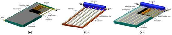
Figure 1.
(a) Flat plate solar collector. (b) Heat pipe evacuated tubes solar collector. (c) Heat pipe flat plate solar collector.
There are several studies on this type of collector, as it is relatively new compared to commercially available collectors. An experimental study on HPFPCs was reported by [29,30], observing the influence of tube geometry and fill percentage on the collector’s performance. They varied the inlet temperature and mass flow for the climate of Cairo. They indicated that the best performance was obtained with an elliptical shape and a specific fill ratio. Wei et al. [31] reported theoretical and experimental results of an HPFPC with ethanol as a heat transfer fluid, finding an increase in the temperature of water in the tank as well as overall efficiency if the vacuum is maintained. These and other works are condensed in [28], in which the thermal performance of three-dimensional HPFPCs is simulated through a parametric study. They indicated the values of several geometry parameters to improve useful heat and instantaneous efficiency. Allouhi et al. [32] offered energy and exergy analysis of the HPFPC, illustrating the impact of diverse design and operating parameters on a whole system in Morocco. They have also shown results for the HPFPC working with several nanofluids. Salhi et al. [33,34] modified the flow structure in a horizontally placed rectangular channel, traversed by an incompressible, turbulent flow of air in forced convection. For the study, the authors created singularities in the flow by inserting vertical baffles and rotating them around the vertical axis. This improved heat transfer in the rectangular duct and increased system efficiency.
Regarding the variety of heat transfer fluids, in [35] the optimal selection of heat transfer fluids (HTFs) for solar thermal applications using multi-criteria decision-making (MCDM) methodologies is investigated. Sixteen HTF alternatives were analyzed based on their thermophysical properties as well as environmental, safety, and economic criteria. By employing approaches, such as the Technique for Order Preference by Similarity to Ideal Solution (TOPSIS) and grey relational analysis, this study aimed to establish an efficient method for identifying the most suitable HTF. The findings indicated that ethylene glycol and propylene glycol are among the five most suitable options after deionized water. Likewise, to mitigate the risk of freezing, the use of antifreeze solutions, such as ethylene glycol or propylene glycol, is essential [7,10]. It was mentioned in [10] that propylene glycol was used as a thermal fluid due to its properties for freeze protection and corrosion inhibition. The study also highlighted that propylene glycol has a low risk in terms of health, environment, fire, and corrosion, making it a suitable choice for solar thermal systems that may be exposed to extreme temperatures. According to the Ashrae Handbook [36], a minimum of 30% ethylene glycol or 35% propylene glycol is recommended to prevent system damage.
A cost and operational feasibility comparison between the FPC and the HPETC was conducted for a 2 m2 collector. Cost and environmental impact were considered for the comparison. According to [37], the cost of an FPC is USD 430. Meanwhile, according to [38], these devices require low maintenance costs thanks to their plate and absorber tube structure. Furthermore, they boast optimal performance for convective heat transfer through the use of different nanofluids. One disadvantage is that they are not recommended in cold climates due to temperature fluctuations. On the other hand, HPETCs have acceptable performance in temperate and cold climates, and can achieve better performance at higher temperatures than FPC collectors. The disadvantage is that, for the same 2 m2 area, these collectors cost up to USD 950 [39]. Another disadvantage is that they require special care during installation due to the fragility of the tubes. Finally, the main advantage of an HPFPC is that it offers better performance than conventional flat plate collectors, improving thermal efficiency under fluctuating weather conditions and reducing manufacturing costs [32]. The cost of the collector is around USD 620. The cost of the mentioned collectors may vary depending on factors such as geographic location, material quality, distribution company, and installation company.
Based on previous studies, evacuated tube solar collectors with wickless heat pipes have not been evaluated with antifreeze fluids at different concentrations. Furthermore, few were found that evaluated the performance of flat plate solar collectors with heat pipes. It was also found that this latter technology is recent and barely under research development. It is not yet commercially available. Therefore, the objective of this study is to evaluate the convective heat transfer coefficient and the performance of low-temperature solar collectors: flat plate solar collectors, evacuated tubes solar collectors with heat pipes, and flat plate solar collectors using wickless heat pipes. The performance of heat transfer fluids, specifically water, ethylene glycol, and propylene glycol at various percentages in these three low-temperature solar collectors is also evaluated.
2. Mathematical Modeling and Simulating
Mathematical modeling, its validation, and simulations are presented in this section for flat plat solar collector, as shown in Figure 1a, as well as heat pipe evacuated tube solar collectors, as shown in Figure 1b, and heat pipe flat plate solar collectors, as shown in Figure 1c.
2.1. Modeling
Modeling of low-temperature solar collectors is presented in this section.
2.1.1. Flat Plate Solar Collectors
The mathematical model of a flat plate solar collector is presented in Figure 2.
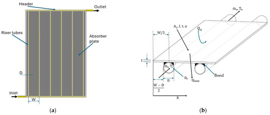
Figure 2.
(a) Flat plate solar collector top view. (b) Cross-sectional view.
The useful heat can be determined as the difference between the useful heat and the heat lost from the solar collector, according to the following, as shown in [40,41]:
where FR and UL are known as the heat removal factor and the overall loss coefficient of the solar collector, and Ta is the ambient temperature.
The instantaneous collector efficiency, ηc is known as the ratio of energy gain to the total radiation collected by the surface of the solar collector, and is determined by the following, as shown in [42]:
The local climatological parameters, including solar radiation, ambient temperature, and wind speed, are used as input parameters for the model. The energy conservation equation is applied to each component of the collector, including the glass cover, absorber plate, air gap, collector insulation, and the working fluid flow in the collector’s pipe network. The continuity and momentum equations are applied to the working fluid flowing inside the riser tubes.
The heat removal factor, also known as the heat dissipation factor FR, is determined as follows:
The collector efficiency factor, F’, is calculated by the following equation, as shown by [43]:
where W, , represent the distance between the fins, the internal diameter, and external diameter of the pipes, respectively. The conductance at the junction is calculated by the equation:
where and b represent the thermal conductivity and the length of the junction, while γ represents the average thickness of the junction.
The standard fin efficiency, F, is determined by the following:
To calculate m, the following equation is used:
where and are respectively the thermal conductivity and the thickness of the absorber.
Convection Heat Transfer Coefficient
The convective heat transfer coefficient hf is determined as follows:
where the Nusselt number is determined, as suggested by [44]:
This relationship is valid for (Re ≤ 2300 for laminar flow and Re > 2300 for turbulent flow).
The dimensionless Peclet, Reynolds, and Prandtl numbers were determined as follows (where Nt is the rise tube number):
Overall Heat Transfer Coefficient
The overall coefficient of losses, UL, is calculated by the following:
where Ut, Ub, Uθ are the upper, lower, and lateral loss coefficients, respectively. The upper loss coefficient, Ut, is determined as follows, as shown in [45]:
where:
where V is the wind speed, N is the number of covers, εp is the emissivity of the plate, εg is the emissivity of the roof, and β is the angle of inclination of the collector, respectively.
The lower loss coefficient, Ub, is determined from the following:
where kb, xb are the thermal conductivity and the thickness of the lower insulation, respectively.
The loss coefficient at the edges is calculated with the following equation:
2.1.2. Heat Pipe Evacuated Tube Solar Collectors
A diagram of an evacuated heat pipe solar collector and a diagram of a wickless heat pipe using the thermosiphon effect are shown in Figure 3a,b, respectively. The modeling of this collector was developed, as suggested by [46].
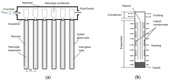
Figure 3.
(a) Diagram of the evacuated heat pipe collector. (b) Diagram of the heat pipe.
The useful heat of the evacuated tube solar collector with heat pipes is determined as follows:
The efficiency of the evacuated tube solar collector with heat pipes is calculated as follows:
The collector heat removal factor can be calculated using Equation (3), where:
The thermal resistant, Rhr and Rcr, are considered by the following:
The thermal resistance of the evaporator is represented by Rhp and is a combination of three resistances: the resistance of the circular fin, the resistance of the copper tube, and the boiling film condensation resistance inside the evaporator tube. Therefore, Rhp can be written as follows:
where, Do,fin, Di,fin, represent the outer and inner diameter of the evaporator, respectively. The values for Le, ke, and Ae indicate the length, conductivity, and area of the evaporator, respectively.
The thermal resistance of the condenser section, Rcond, which is the sum of the film condensation resistance in the condenser, the copper pipe section of the condenser, and the dry manifold condenser resistance. The thermal contact resistance in the dry condenser is assumed to be insignificant.
where Do,c and Di,c, are the outside and inside diameter of the condenser, and Do,man, Di,man, kman, and Lman are the outer and inner diameter, conductivity, and length of the manifold, respectively.
The thermal resistance due to radiation is Rrad, which can be calculated and represented as follows:
Evaporator Heat Transfer Coefficient
The convection heat transfer coefficient in the evaporator, he, is determined as follows:
where g, is the gravity and Tp and Tk are temperature of the plate and sky, respectively; , kl, and are the density, conductivity, and viscosity of the liquid, respectively; , hfg, are the vapor density and phase change enthalpy, respectively.
Condenser Heat Transfer Coefficient
The convection heat transfer coefficient in the condenser, hc, is determined as follows:
2.1.3. Heat Pipe Flat Plate Solar Collectors
The mathematical formulation was based on the works of [28,32,46]. This formulation relies on a set of coupled heat transfer equations to identify temperature distributions in various parts of the collector. At each time step, the model can predict the spatial temperatures on the glass cover, the absorbing surface, the evaporator, the condenser, and the water flowing inside the collector, as shown in Figure 4.
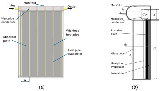
Figure 4.
(a) Diagram of the heat pipe. (b) Diagram of the evacuated heat pipe collector.
The heat flow lost by the condenser towards the manifold liquid, is determined as follows:
where Tc is the condenser temperature, equal to the evaporator temperature, and , the average temperature, is determined as follows:
The heat flow in the manifold is the useful heat of the collector and is determined as follows:
The instantaneous efficiency of a solar collector as a function of the number of its heat pipes is determined as follows:
where lev is the length of the evaporator, Np is the number of tubes, W is the space between tubes.
Condenser Heat Transfer Coefficient
The convective heat transfer coefficient between the condenser and the work fluid in the manifold , for both laminar flow and turbulent flow, taken from [26], was determined as follows:
where the dimensionless numbers are as follows:
2.2. Model Validation
The mathematical model presented in Section 2.1 was programmed in the specialized software Engineering Equation Solver (EES), which solves and identifies a set of equations and/or simultaneous operations [47]. The mathematical models were validated by comparing the results obtained in this work with those published by [30,46,48] for flat plate, evacuated tube, and flat plate collectors with heat pipes, respectively, using the data in Table 1. The values of radiation, as well as ambient and entrance temperature to collector were 750 W/m2, 23 °C and 25 °C, respectively.

Table 1.
Basic characteristics and specifications of the different solar collectors.
Figure 5 shows the validation results, with the relative error for each collector evaluated. From Figure 5, the maximum error was less than 6.2%, −4.5%, and 0.8% for the flat plate, evacuated tube, and flat plate collectors with vacuum tubes, respectively. Figure 5a shows the efficiency behavior with respect to mass flow rate, where the same trend as the efficiency results can be seen compared to those shown by [47]. Figure 5b presents the relative error of the results compared to [47]. From the figure, a maximum error of 6.2% is observed. This may be due to the uncertainty in the thermophysical properties of the fluids. Figure 5c shows the collector efficiency with respect to the working fluid inlet temperature. The results were consistent with those of [46]. Figure 5d shows a maximum error of −4.5%. Furthermore, this figure shows that the error is greater at a low working fluid inlet temperature. As this temperature increases, the error approaches 0%. Figure 5e shows the collector efficiency over a period of the day. The results are very similar to those shown by [30]. Therefore, the error shown in Figure 5f is as low as 0.8%. According to the error shown in the validation and in [49,50], which state that, if the error is at most 10%, the results present a good validation. Therefore, the mathematical models of Section 2.1, with different operating conditions, were used for the simulation of the three types of collectors evaluated here. Through a sensitivity analysis, it was found that the condensation temperature had the greatest effect on the accuracy of the model.
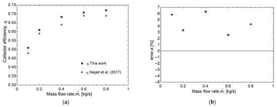
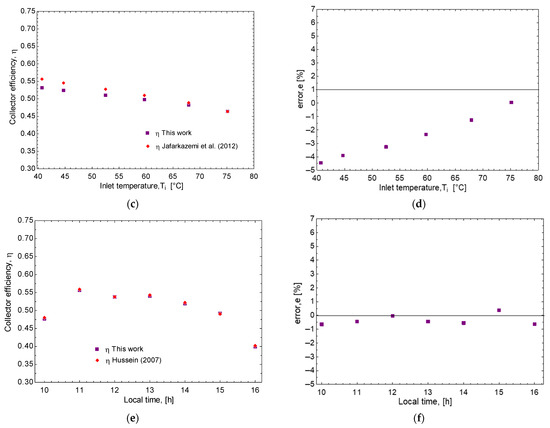
Figure 5.
Efficiency results compared to the literature and error: (a,b) flat plate solar collector; (c,d) heat pipe evacuated tubes solar collector; (e,f) heat pipe flat plate solar collector [30,46,48].
2.3. Simulation
The mathematical model presented in Section 2.1 was programmed in the specialized software Engineering Equation Solver (EES) [47].
2.3.1. Specifications and Properties
The specifications of the solar collectors evaluated are presented in Table 2. The working fluids evaluated were water, water–ethylene glycol, EG 30%, water–propylene glycol, PG 30%, water–ethylene glycol, EG 50%, water–propylene glycol, PG 50%. The thermophysical properties of these evaluated fluids were obtained from [47] and are presented in Table 3. The range of each evaluated parameter is presented in Table 4.
Table 2.
Basic characteristics and specifications of the different evaluated solar collectors.
Table 3.
Thermophysical properties of evaluated working fluids.
Table 4.
Range of evaluated parameters.
2.3.2. Assumptions
The assumptions made for each of the collectors are presented below for each of the solar collector systems.
Flat plate solar collectors:
- -
- The absorber area of the collector is always at a uniform temperature.
- -
- The temperature gradient along the thickness of the absorber and around its perimeter is neglected.
- -
- Since the evaporator section is subject to a constant heat flux, and phase change occurs at a constant temperature, the temperature gradient along the longitudinal direction is negligible.
- -
- The thermal contact resistance between the absorber area and the evaporator tube, and between the condenser section and the manifold, is neglected.
- -
- The connection between the evaporator and condenser of the heat pipe is assumed to be adiabatic.
Thermosiphon evacuated solar collectors:
- -
- The mathematical model is one-dimensional.
- -
- The thermal resistance caused by the welding between the absorber and the heat pipes is neglected.
- -
- Inside the heat pipe, the vapor temperature is the same as the saturation value at the given pressure.
- -
- The thermophysical properties of all solid substances are constant.
- -
- The properties of the working fluid depend on the temperature.
Thermosiphon flat plate solar collectors:
- -
- Fully developed flow and stable conditions.
- -
- The ambient temperature at the top and bottom of the collector are the same.
- -
- Negligible addition to the collector surface by the header.
- -
- In all pipes, the fluid is in uniform flow.
3. Results and Discussion
In this section, the simulation results are presented with the model presented in Section 2, for the three types of low temperature solar collectors: flat plate, evacuated tubes, and flat plate with heat pipes. The simulation results are presented for the five working fluids evaluated: water, water–ethylene glycol at 30% (EG 30%), water–ethylene glycol at 50% (EG 50%), water–propylene glycol at 30% (PG 30%), water–propylene glycol at 50% (PG 50%). The performance parameters evaluated include useful heat, Qu, efficiency, η, and heat transfer coefficient, h. The varied parameters include mass flow rate, fluid temperature, ambient temperature, and radiation.
3.1. Influence of Temperature and Working Fluid on Performance
The influence of the fluid temperature on the useful heat and efficiency of the collector, with respect to the mass flow rate at three different temperatures, is presented in Figure 6. In the range of mass flow evaluated, as shown in Figure 6a,b, the almost constant efficiency and useful heat can be seen. However, if these performance parameters are compared at different fluid temperatures, it is observed that the efficiency decreases from 0.70 to 0.58 and 0.48 with the flat plate collector for temperatures of 30 °C, 40 °C, and 50 °C, respectively. While for the evacuated tube collector, the efficiency decreases from 0.83 to 0.80 and 0.75 for the same temperatures of 30 °C, 40 °C, and 50 °C.
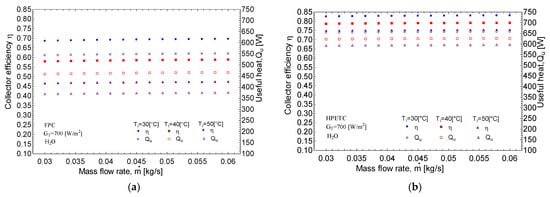
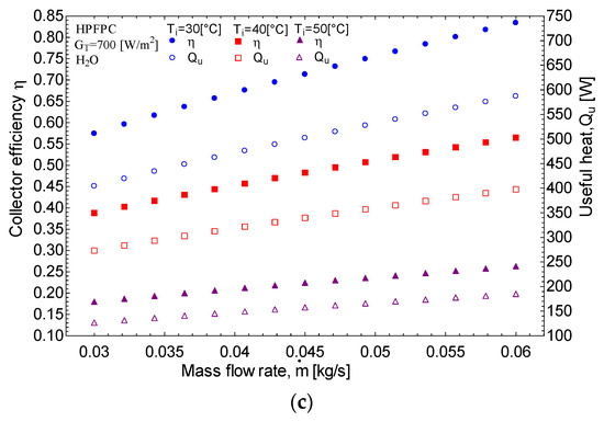
Figure 6.
Results of efficiency and useful heat with respect to the mass flow rate of the fluid at different temperatures for the three types of solar collectors: (a) flat plate, (b) evacuated tubes, (c) flat plate with heat pipes.
When evaluating the performance of the HPFPC, as shown in Figure 6c, a clear trend emerges indicating that both efficiency and useful heat increase with an increase in the mass flow rate. For instance, at a fluid temperature of 40 °C, the efficiency rises from 0.38 to 0.55, while the useful heat increases from 300 W to 400 W, respectively. However, the figure also illustrates that both efficiency and useful heat decrease with rising temperature. Specifically, at a mass flow rate of 0.045 kg/s, the efficiency declines from 0.73 to 0.50 and further to 0.23 for fluid temperatures of 30 °C, 40 °C, and 50 °C, respectively. This information underscores the significant impact of temperature and mass flow on the performance of solar collectors.
Figure 7 shows the efficiency, with respect to the mass flow rate of the five working fluids evaluated for the three types of low temperature solar collectors. Based on the observations presented in Figure 7a, the efficiency of the FPC operating at a mass flow rate of 0.045 kg/s demonstrates only a marginal decrease of 0.2% when utilizing a mixture of water and 30% ethylene glycol, and a slightly greater reduction of 0.4% when the mixture is composed of 50% ethylene glycol. Notably, the reduction in efficiency is even less pronounced when propylene glycol is employed. Similarly, as illustrated in Figure 7b, the efficiency of the HPETC exhibits decreases of 0.1% and 0.2% for the same concentrations of ethylene glycol solutions. From the analysis of these two figures, the variations in efficiency are negligible when utilizing either pure water or mixtures containing less than 50% ethylene glycol or propylene glycol in both flat plate collectors and evacuated tube collectors.
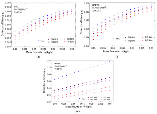
Figure 7.
Efficiency vs. mass flow for five different working fluids and for three different solar collectors: (a) flat plate solar collector, (b) evacuated tubes solar collector, (c) flat plate with heat pipes solar collector.
However, as illustrated in Figure 7c, the efficiency of the HPFPC at a mass flow rate of 0.045 kg/s experiences a significant decline, dropping from 72% to 48% when a mixture containing 30% ethylene glycol is utilized. If the concentration of ethylene glycol is increased to 50%, efficiency further decreases to 36%. By contrast, the reduction in efficiency when using propylene glycol mixtures is relatively minor. This observed decrease in performance for the flat plate solar collector incorporating heat pipes is attributable to the integration of two distinct technologies: the flat plate collector, which inherently operates at a lower efficiency, and the heat pipes, which provide enhanced efficiency. Consequently, the combination of these two technologies results in a combined efficiency. To improve the efficiency of heat pipe flat panel solar collectors (HPFPCs) using mixtures of water with ethylene glycol and propylene glycol, one could insert improved surfaces into the heat pipe or place heat sinks on the condenser, or even experiment with nanofluids.
3.2. Convective Heat Transfer Coefficient Results
The convective heat transfer coefficient, hc, was determined for the HPFPC using Equation (35). For the HPETC, the useful heat was first determined using Equation (21). Subsequently, the hc, in the condenser was determined by solving it for Equation (31). Figure 8 illustrates the heat transfer coefficient in relation to fluid temperature for both the HPETC and the HPFPC. The data reveal that the heat transfer coefficient for the HPETC increases at approximately 159 W/m2 K for each degree Celsius. By contrast, the increase for the HPFPC using water is much lower, at 22 W/m2 K per degree Celsius. Similar growth rates are observed with ethylene glycol and propylene glycol; however, the heat transfer coefficient for fluid mixtures is notably lower than that for pure water.
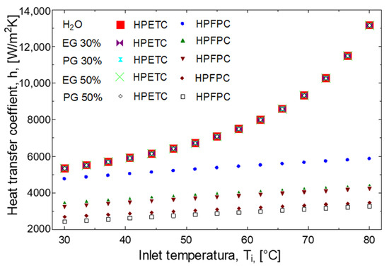
Figure 8.
Heat transfer coefficient in the condenser, on the manifold side, with respect to the inlet temperature to the manifold, of the two collectors with heat pipes.
Moreover, for the HPFPC, the heat transfer coefficient diminishes by 28% and 41% when antifreeze solutions are applied at concentrations of 30% and 50%, respectively. This was previously demonstrated by [14], where they show how collector efficiency decreases as the percentage of antifreeze increases. To counteract the decrease in the heat transfer coefficient, the mass flow rate could be increased, as can be seen in Figure 6c and Figure 7c, which show that the collector efficiency increases with mass flow. This variation in growth rates of the heat transfer coefficients is likely attributed to the differing factors impacting each collector type. In the HPETC, the heat removal factor is influenced by all collector components, including the spacing of the tubes and the properties of the circulating fluid within the evaporator. By contrast, the heat transfer coefficient for the HPFPC reflects the conditions of the fluid receiving heat from the condenser of the heat pipes located inside the manifold [29,30,32].
3.3. Performance of Low-Temperature Solar Collectors with Antifreeze Fluids
Figure 9 presents the efficiency and useful heat concerning fluid temperature for three types of solar collectors and five different antifreeze working fluids, under fixed mass flow and radiation conditions. As shown in Figure 9a, when comparing the heat pipe flat plate collector (HPFPC) with other common collectors, the efficiency of the flat plate collector (FPC) decreases significantly from 70% to 8% at a rate of 1.2% for each degree Celsius increase in temperature. By comparison, the efficiency of the evacuated tube collector (HPETC) drops from 83% to 58%, decreasing at a rate of 0.5% per degree Celsius. Conversely, for the HPFPC—with water as the working fluid—the efficiency declines more steeply from 83% to 29% at a rate of 1% for each degree Celsius. When evaluating a 30% antifreeze mixture, the efficiency reduces from 60% to 21.5% at a rate of 0.77% per degree Celsius.
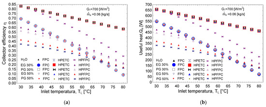
Figure 9.
Efficiency and useful heat with respect to the fluid temperature, for the three types of solar collectors and the five antifreeze working fluids: (a) efficiency, (b) useful heat.
The figure further indicates that, for fluid temperatures below 50 °C, the efficiency of the HPFPC is lower than that of the standard flat plate collector. However, above 50 °C, the HPFPC outperforms the flat plate collector. Specifically, at temperatures below 50 °C, using water can result in a 19% efficiency increase, while the use of antifreeze mixtures leads to up to a 13% reduction in efficiency. At a fluid temperature of 50 °C, both water and antifreeze mixtures maintain the same efficiency—19% for water and a similar performance for antifreeze. As the temperature rises to 65 °C, the efficiency increases by 19% for water and 7% for antifreeze mixtures. At 80 °C, these increases are 21% for water and 13% for antifreeze mixtures. The trends in useful heat, as shown in Figure 9b, mirror those of efficiency, indicating that the use of heat pipes in flat plate solar collectors can enhance efficiency by up to 21% when operating at fluid temperatures above 50 °C. According to [51,52], and the trend presented in Figure 8, it can be expected that, with mixtures of 20% ethylene glycol and/or propylene glycol, the efficiency of the heat pipe flat plate solar collector can improve compared to the use of 30% of these antifreezes, and that it still protects the equipment against freezing.
3.4. Standardized Efficiency of Low Temperature Solar Collectors
To evaluate the relevance of using heat pipes in flat plate solar collectors, this section presents the efficiency with respect to specific environmental conditions, ambient temperature, Ta, and radiation, I, represented by the Hottel–Willier–Bliss coefficient . This coefficient helps to visualize the efficiency of solar collectors throughout the operating range of a day, typically where the three parameters that affect the collector vary: ambient temperature, radiation, and fluid temperature. For this, the values of radiation, ambient temperature, and fluid temperature from [30] have been used, presented in [32] and in Table 5.
Table 5.
Environmental and fluid values used for standardized efficiency [32].
Figure 10 illustrates the efficiency of three types of low-temperature solar collectors—FPCs, HPETCs, and HPFPCs—throughout a typical day in relation to the Hottel–Willier–Bliss coefficient. The analysis was conducted at a mass flow rate of 0.05 kg/s, consistent with the methodology of [32]. From the figure, it can be seen that, as the temperature difference between the fluid inlet and the ambient temperature increases, the collector’s efficiency decreases. This occurs because overall losses increase when the temperature of a hot body is higher than the ambient temperature. This is true for all three collectors evaluated. As depicted in Figure 10a, the efficiency of the evacuated tube collector surpasses that of the flat plate collector by up to 15%. Additionally, the integration of heat pipes within a flat plate collector can enhance its efficiency by as much as 9%, particularly noticeable around 14:00 h. During this evaluation, solar radiation levels ranged from approximately 360 to 800 W/m2. Figure 10b further demonstrates that the efficiency of flat plate solar collectors can increase by up to 6.5% when heat pipes are incorporated.
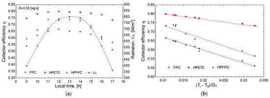
Figure 10.
Efficiency of low temperature solar collectors: (a) for a typical day, and (b) with respect to the Hottel–Willier–Bliss coefficient.
It is fundamental to consider the synergistic effects between fluid properties—such as thermal conductivity, viscosity, and specific heat capacity—and the physical design of HPFPCs on the overall efficiency of the solar collector system. Water has higher thermal conductivity and specific heat capacity than most antifreeze solutions, enhancing the overall heat transfer process and improving the thermal performance of the HPFPC. By contrast, antifreeze solutions typically have higher viscosity, particularly at lower temperatures, which can reduce heat transfer efficiency. The design of the HPFPC plays an important role in determining fluid performance, as factors such as the arrangement of heat pipes, the available heat exchange surface area, and the thermal insulation properties interact with the characteristics of the heat transfer fluid. As demonstrated, the heat transfer coefficients of antifreeze solutions tend to be lower than those of water; however, this study identifies the operating conditions under which the collector’s performance approaches that of water.
The results imply that the integration of heat pipes in flat plate collectors can improve efficiency by up to 13%. The comparative evaluation of heat transfer fluids, including varying concentrations of ethylene glycol and propylene glycol, provides valuable guidance for engineers in selecting suitable fluids that not only achieve efficiency standards but mitigate the risk of freezing in colder climates. The variations in operational conditions, such as fluid temperature and flow rates, were found to impact efficiency. This information can be utilized by engineers to design systems that operate under specific conditions, leading to better energy resource management. It is fundamental to consider the synergistic effects between fluid properties—such as thermal conductivity, viscosity, and specific heat capacity—and the physical design of HPFPCs on the overall efficiency of the solar collector system. Water has higher thermal conductivity and specific heat capacity than most antifreeze solutions, enhancing the overall heat transfer process and improving the thermal performance of the HPFPC. By contrast, antifreeze solutions typically have higher viscosity, particularly at lower temperatures, which can reduce heat transfer efficiency. The design of the HPFPC plays an important role in determining fluid performance, as factors such as the arrangement of heat pipes, the available heat exchange surface area, and the thermal insulation properties interact with the characteristics of the heat transfer fluid. As demonstrated, the heat transfer coefficients of antifreeze solutions tend to be lower than those of water; however, this study identifies the operating conditions under which the collector’s performance approaches that of water.
4. Conclusions
The results obtained in this study emphasize the need for a detailed analysis of the performance characteristics of solar collection systems, such as the flat plate collector (FPC), the heat pipe evacuated tube collector (HPETC), and the heat pipe flat plate collector (HPFPC) under various operating conditions. The most important conclusions include the following.
The heat transfer coefficient in the HPFPC decreases by 28% and 41% when 30% and 50% antifreeze concentrations are used. Overall, the integration of heat pipes in flat plate solar collectors can enhance efficiency by as much as 6.5% compared to traditional FPCs, highlighting the importance of fluid composition and operating conditions in optimizing thermal performance.
The results show that the use of antifreeze fluids in flat plate or evacuated tube collectors results in a minimal efficiency change of approximately 0.5%. By contrast, utilizing antifreeze in the HPFPC leads to more significant reductions in efficiency, specifically by 10% and 32% for 30% and 50% ethylene glycol mixtures, respectively. However, at a fluid temperature of 30 °C with antifreeze, the efficiency is diminished by 10% and 15% for 30% and 50% antifreeze concentrations, respectively. Notably, at a temperature of 50 °C, the efficiency of both systems converges. At higher fluid temperatures of 80 °C, efficiency enhancements of 13% and 8% are recorded for antifreeze concentrations of 30% and 50%, respectively. When water is used as the working fluid in the HPFPC, efficiency gains of up to 13% and 21% are observed at fluid temperatures of 30 °C and 80 °C, respectively.
The influence of fluid properties on system performance is highlighted, as well as the need for careful consideration of working fluid composition and operating conditions in improving thermal efficiency across different solar collector systems. Future work should be oriented on the study of several nano-fluids, long-term performance, and the economic viability of these systems.
Author Contributions
Conceptualization, J.M.C., G.G.-U., and A.Z.; methodology, J.M.C., G.G.-U., J.E.D.L.-R., and A.Z.; software, J.M.C., J.B., R.B., R.M.-M., and A.Z.; validation, J.E.D.L.-R., J.B., G.R., and A.Z.; formal analysis, J.M.C., J.E.D.L.-R., G.G.-U., and A.Z.; investigation, J.M.C., G.R., and A.Z.; resources, J.B., G.R., S.E.C., and A.Z.; data curation, J.M.C., J.E.D.L.-R., G.G.-U., G.R., and A.Z.; writing—original draft preparation, J.M.C., and A.Z.; writing—review and editing, J.M.C., G.G.-U., O.G., and A.Z.; visualization, G.R., O.G., and S.E.C.; supervision, A.Z.; project administration, A.Z.; funding acquisition, G.R., S.E.C., and A.Z. All authors have read and agreed to the published version of the manuscript.
Funding
The financial support of this study by the science research grant SIP20240693, and by the Instituto Politécnico Nacional, IPN, is greatly appreciated.
Institutional Review Board Statement
Not applicable.
Informed Consent Statement
Not applicable.
Data Availability Statement
The original contributions presented in this study are included in the article. Further inquiries can be directed to the corresponding authors.
Acknowledgments
The financial support of this study by the science research grant SIP20250693, by the Instituto Politécnico Nacional, IPN, is greatly appreciate. The Authors also acknowledge the financial support given for the postgraduate students by the National Board of Science and Technology, CONACYT, of Mexico.
Conflicts of Interest
The authors declare no conflicts of interest.
Nomenclature
| A | area (m2), absorber |
| b | joint length (m) |
| Cp | heat capacity (kJ/kg K) |
| diameter (m) | |
| standard fin efficiency | |
| heat removal factor | |
| solar collector efficiency factor | |
| heat transfer coefficient (W/m2 K) | |
| solar radiation (W/m2) | |
| thermal conductivity (W/m K) | |
| mass flow rate (kg/s) | |
| Nusselt number | |
| Prandtl number | |
| heat flux (W) | |
| global heat transfer coefficient (W/m K) | |
| Reynolds number | |
| temperature (K) | |
| distance between fins (m) | |
| Subscripts | |
| ambient | |
| b | joint between fins and pipes, lower loss |
| absorber | |
| evaporator, border surface | |
| glass | |
| inlet, internal | |
| external | |
| flat plate | |
| useful | |
| Greek symbols | |
| α | absorptance |
| absorber thickness (m) | |
| efficiency | |
| viscosity (Pa*s) | |
| density (kg/m3) | |
| Boltzmann constant (W/m2 K4) | |
| transmittance | |
Abbreviations
| EES | Engineering Equation Solver |
| EG | Ethylene glycol |
| FPC | Flat plate solar collector |
| HPETC | Heat pipe evacuated tube solar collector |
| HPFPC | Heat pipe flat plate solar collector |
| NASA | National Aeronautics and Space Administration |
| PG | Propylene glycol |
References
- National Aeronautics and Space Administration. Available online: https://science.nasa.gov/climate-change/ (accessed on 14 February 2025).
- Leonard, M.D.; Michaelides, E.E. Grid-Independent Residential Buildings with Renewable Energy Sources. Energy 2018, 148, 448–460. [Google Scholar] [CrossRef]
- Taibi, E.; Gielen, D.; Bazilian, M. The Potential for Renewable Energy in Industrial Applications. Renew. Sustain. Energy Rev. 2012, 16, 735–744. [Google Scholar] [CrossRef]
- Ramachandran, T.; Mourad, A.-H.I.; Hamed, F. A Review on Solar Energy Utilization and Projects: Development in and around the UAE. Energies 2022, 15, 3754. [Google Scholar] [CrossRef]
- Pascaris, A.S.; Schelly, C.; Burnham, L.; Pearce, J.M. Integrating Solar Energy with Agriculture: Industry Perspectives on the Market, Community, and Socio-Political Dimensions of Agrivoltaics. Energy Res. Soc. Sci. 2021, 75, 102023. [Google Scholar] [CrossRef]
- Kabir, E.; Kumar, P.; Kumar, S.; Adelodun, A.A.; Kim, K.-H. Solar Energy: Potential and Future Prospects. Renew. Sustain. Energy Rev. 2018, 82, 894–900. [Google Scholar] [CrossRef]
- Guo, Y.; Mo, Z.; Zhang, R.; Wang, D.; Fan, J. Thermal–Hydraulic Performance of Flat-Plate Solar Collector Plant Using Different Heat-Transfer Fluids. Energy Technol. 2024, 12, 2400412. [Google Scholar] [CrossRef]
- Gholipour, S.; Afrand, M.; Kalbasi, R. Introducing Two Scenarios to Enhance the Vacuum U-Tube Solar Collector Efficiency by Considering Economic Criterion. J. Taiwan. Inst. Chem. Eng. 2021, 124, 228–237. [Google Scholar] [CrossRef]
- Sabiha, M.A.; Saidur, R.; Mekhilef, S.; Mahian, O. Progress and Latest Developments of Evacuated Tube Solar Collectors. Renew. Sustain. Energy Rev. 2015, 51, 1038–1054. [Google Scholar] [CrossRef]
- Shojaeizadeh, E.; Veysi, F.; Yousefi, T.; Davodi, F. An Experimental Investigation on the Efficiency of a Flat-Plate Solar Collector with Binary Working Fluid: A Case Study of Propylene Glycol (PG)–Water. Exp. Therm. Fluid. Sci. 2014, 53, 218–226. [Google Scholar] [CrossRef]
- Kalogirou, S.A. Solar Energy Engineering; Elsevier: Amsterdam, The Netherlands, 2014; ISBN 9780123972705. [Google Scholar]
- Ahmadi, A.; Ehyaei, M.A.; Doustgani, A.; Assad, M.E.H.; Esmaeilion, F.; Hmida, A.; Jamali, D.H.; Kumar, R.; Li, Z.X.; Razmjoo, A. Recent Progress in Thermal and Optical Enhancement of Low Temperature Solar Collector. Energy Syst. 2023, 14, 1–40. [Google Scholar] [CrossRef]
- Al-Mamun, M.R.; Roy, H.; Islam, M.S.; Ali, M.R.; Hossain, M.I.; Saad Aly, M.A.; Hossain Khan, M.Z.; Marwani, H.M.; Islam, A.; Haque, E.; et al. State-of-the-Art in Solar Water Heating (SWH) Systems for Sustainable Solar Energy Utilization: A Comprehensive Review. Sol. Energy 2023, 264, 111998. [Google Scholar] [CrossRef]
- Huminic, G.; Huminic, A. Capabilities of Advanced Heat Transfer Fluids on the Performance of Flat Plate Solar Collector. Energy Rep. 2024, 11, 1945–1958. [Google Scholar] [CrossRef]
- Jafarkazemi, F.; Ahmadifard, E. Energetic and Exergetic Evaluation of Flat Plate Solar Collectors. Renew. Energy 2013, 56, 55–63. [Google Scholar] [CrossRef]
- Alshukri, M.J.; Kadhim Hussein, A.; Eidan, A.A.; Alsabery, A.I. A Review on Applications and Techniques of Improving the Performance of Heat Pipe-Solar Collector Systems. Sol. Energy 2022, 236, 417–433. [Google Scholar] [CrossRef]
- Jose, J.; Kumar Hotta, T. A Comprehensive Review of Heat Pipe: Its Types, Incorporation Techniques, Methods of Analysis and Applications. Therm. Sci. Eng. Prog. 2023, 42, 101860. [Google Scholar] [CrossRef]
- Al-azmi, Y.K.; Sakr, R.Y.; Abdelatif, O.E.; Elsemary, I.M.M. Experimental Investigation of an Evacuated Tube Heat Pipe Solar Collector Using Different Fluids. Eng. Res. J. Fac. Eng. 2022, 51, 1–12. [Google Scholar] [CrossRef]
- Savino, R.; di Francescantonio, N.; Fortezza, R.; Abe, Y. Heat Pipes with Binary Mixtures and Inverse Marangoni Effects for Microgravity Applications. Acta Astronaut. 2007, 61, 16–26. [Google Scholar] [CrossRef]
- Arab, M.; Abbas, A. Model-Based Design and Analysis of Heat Pipe Working Fluid for Optimal Performance in a Concentric Evacuated Tube Solar Water Heater. Sol. Energy 2013, 94, 162–176. [Google Scholar] [CrossRef]
- Ersöz, M.A. Effects of Different Working Fluid Use on the Energy and Exergy Performance for Evacuated Tube Solar Collector with Thermosyphon Heat Pipe. Renew. Energy 2016, 96, 244–256. [Google Scholar] [CrossRef]
- Yadav, A.; Bajpai, V.K. Comparison of Thermal Performances of Flat Plate and Evacuated Tube Solar Air Collector at Different Flow Rates: Experimental Analysis. Int. J. Renew. Energy Technol. 2013, 4, 107. [Google Scholar] [CrossRef]
- Olczak, P.; Matuszewska, D.; Zabagło, J. The Comparison of Solar Energy Gaining Effectiveness between Flat Plate Collectors and Evacuated Tube Collectors with Heat Pipe: Case Study. Energies 2020, 13, 1829. [Google Scholar] [CrossRef]
- Ayompe, L.M.; Duffy, A.; Mc Keever, M.; Conlon, M.; McCormack, S.J. Comparative Field Performance Study of Flat Plate and Heat Pipe Evacuated Tube Collectors (ETCs) for Domestic Water Heating Systems in a Temperate Climate. Energy 2011, 36, 3370–3378. [Google Scholar] [CrossRef]
- Morrison, G.L.; Budihardjo, I.; Behnia, M. Water-in-Glass Evacuated Tube Solar Water Heaters. Sol. Energy 2004, 76, 135–140. [Google Scholar] [CrossRef]
- Kalair, A.R.; Seyedmahmoudian, M.; Saleem, M.S.; Abas, N.; Rauf, S.; Stojcevski, A. A Comparative Thermal Performance Assessment of Various Solar Collectors for Domestic Water Heating. Int. J. Photoenergy 2022, 2022, 9536772. [Google Scholar] [CrossRef]
- Greco, A.; Gundabattini, E.; Gnanaraj, D.S.; Masselli, C. A Comparative Study on the Performances of Flat Plate and Evacuated Tube Collectors Deployable in Domestic Solar Water Heating Systems in Different Climate Areas. Climate 2020, 8, 78. [Google Scholar] [CrossRef]
- Zhang, D.; Tao, H.; Wang, M.; Sun, Z.; Jiang, C. Numerical Simulation Investigation on Thermal Performance of Heat Pipe Flat-Plate Solar Collector. Appl. Therm. Eng. 2017, 118, 113–126. [Google Scholar] [CrossRef]
- Hussein, H.M.S.; El-Ghetany, H.H.; Nada, S.A. Performance of Wickless Heat Pipe Flat Plate Solar Collectors Having Different Pipes Cross Sections Geometries and Filling Ratios. Energy Convers. Manag. 2006, 47, 1539–1549. [Google Scholar] [CrossRef]
- Hussein, H.M.S. Theoretical and Experimental Investigation of Wickless Heat Pipes Flat Plate Solar Collector with Cross Flow Heat Exchanger. Energy Convers. Manag. 2007, 48, 1266–1272. [Google Scholar] [CrossRef]
- Wei, L.; Yuan, D.; Tang, D.; Wu, B. A Study on a Flat-Plate Type of Solar Heat Collector with an Integrated Heat Pipe. Sol. Energy 2013, 97, 19–25. [Google Scholar] [CrossRef]
- Allouhi, A.; Benzakour Amine, M.; Buker, M.S.; Kousksou, T.; Jamil, A. Forced-Circulation Solar Water Heating System Using Heat Pipe-Flat Plate Collectors: Energy and Exergy Analysis. Energy 2019, 180, 429–443. [Google Scholar] [CrossRef]
- Salhi, J.E.; Salhi, M.; Amghar, K.; Zarrouk, T.; Salhi, N. & S.N. Analysis of the Thermohydrodynamic Behavior of a Cooling System Equipped with Adjustable Fins Crossed by the Turbulent Flow of Air in Forced Convection. Int. J. Energy Environ. Eng. 2022, 13, 1039–1051. [Google Scholar]
- Salhi, J.-E.; Zarrouk, T.; Hmidi, N.; Salhi, M.; Salhi, N.; Chennaif, M. Three-Dimensional Numerical Analysis of the Impact of the Orientation of Partially Inclined Baffles on the Combined Mass and Heat Transfer by a Turbulent Convective Airflow. Int. J. Energy Environ. Eng. 2023, 14, 79–94. [Google Scholar] [CrossRef]
- Kumar, P.G.; Yuvaraj, N.; Kumaresan, V.; Velraj, R. Selection of Heat Transfer Fluids for Solar Thermal Applications Using Multi-Criteria Decision-Making Tools. J. Test. Eval. 2020, 48, 595–612. [Google Scholar] [CrossRef]
- ASHRAE. ASHRAE Handbook: Fundamentals, Inch-Pound Edition; American Society of Heating, Refrigerating and Air-Conditioning: Atlanta, GA, USA, 2005; ISBN 1931862702. [Google Scholar]
- Modulo Solar. Sistemas y Equipos Solares para Calentamiento de agua. [on line]. Módulo Solar. 2025. Available online: https://modulosolar.com/mx/ (accessed on 10 January 2025).
- Sharma, A.; Gunreddy, N.; Mulamalla, A.R.; Duraisamy, S.; Sivan, S.; Poongavanam, G.K.; Kumar, B. Conductive and Convective Heat Transfer Augmentation in Flat Plate Solar Collector from Energy, Economic and Environmental Perspectives—A Comprehensive Review. Environ. Sci. Pollut. Res. 2022, 29, 87019–87067. [Google Scholar] [CrossRef]
- Mthembu, N.; Tartibu, L.; Mukuna, J.G. Numerical Analysis of Evacuated Tube Solar Collector with Heat Pipe Containing an I-Section Insert. Arab. J. Sci. Eng. 2023, 48, 3961–3976. [Google Scholar] [CrossRef]
- Hawwash, A.A.; Ahamed, M.; Nada, S.A.; Radwan, A.; Abdel-Rahman, A.K. Thermal Analysis of Flat Plate Solar Collector Using Different Nanofluids and Nanoparticles Percentages. IEEE Access 2021, 9, 52053–52066. [Google Scholar] [CrossRef]
- Cruz, J.M.; Crepaldi, S.A.; Gutiérrez-Urueta, G.L.; de Rubio, J.J.; Zacarías, A.; Jiménez, C.; Romage, G.; Jiménez, J.A.; López, A.; Balcazar, R. Performance Assessment of Flat Plate Solar Collector Using Simple and Hybrid Carbon Nanofluids at Low Thermal Capacity. Appl. Sci. 2024, 14, 8732. [Google Scholar] [CrossRef]
- García, A.; Martin, R.H.; Pérez-García, J. Experimental Study of Heat Transfer Enhancement in a Flat-Plate Solar Water Collector with Wire-Coil Inserts. Appl. Therm. Eng. 2013, 61, 461–468. [Google Scholar] [CrossRef]
- Kalogirou, S.A. Solar Energy Engineering: Processes and Systems, 2nd ed.; Academic Press: Cambridge, MA, USA, 2023. [Google Scholar]
- Sint, N.K.C.; Choudhury, I.A.; Masjuki, H.H.; Aoyama, H. Theoretical Analysis to Determine the Efficiency of a CuO-Water Nanofluid Based-Flat Plate Solar Collector for Domestic Solar Water Heating System in Myanmar. Sol. Energy 2017, 155, 608–619. [Google Scholar] [CrossRef]
- Kletn, S.A. Calculation of Fiat-Plate Collector Loss Coefficients* Q~ =; Pergamon Press: Oxford, UK, 1975; Volume 17. [Google Scholar]
- Jafarkazemi, F.; Abdi, H. Evacuated Tube Solar Heat Pipe Collector Model and Associated Tests. J. Renew. Sustain. Energy 2012, 4, 023101. [Google Scholar] [CrossRef]
- Klein, S.A. Engineering Equation Solver, 1992–2015; F-Chart Software: Madison, WI, USA, 2018. [Google Scholar]
- Nejad, M.B.; Mohammed, H.A.; Sadeghi, O.; Zubeer, S.A. Influence of Nanofluids on the Efficiency of Flat-Plate Solar Collectors (FPSC). In Proceedings of the E3S Web of Conferences; EDP Sciences, Surabaya, Indonesia, 7 November 2017; Volume 22. [Google Scholar]
- Rahimi, M.H.; Shayganmanesh, M.; Noorossana, R.; Pazhuheian, F. Modelling and Optimization of Laser Engraving Qualitative Characteristics of Al-SiC Composite Using Response Surface Methodology and Artificial Neural Networks. Opt. Laser Technol. 2019, 112, 65–76. [Google Scholar] [CrossRef]
- Guang, W.; Baraldo, M.; Furlanut, M. Calculating Percentage Prediction Error: A User’s Note. Pharmacol. Res. 1995, 32, 241–248. [Google Scholar] [CrossRef] [PubMed]
- Mokon Heat Transfer Fluid—Ethylene Glycol. 2025. Available online: https://www.mokon.com/products/fluids/glycol-solutions/pdf/Ethylene-Glycol-Technical-Data.pdf (accessed on 14 February 2025).
- Mokon Heat Transfer Fluid—Propylene Glycol. 2025. Available online: https://www.mokon.com/products/fluids/glycol-solutions/pdf/Propylene-Glycol-Technical-Data.pdf (accessed on 14 February 2025).
Disclaimer/Publisher’s Note: The statements, opinions and data contained in all publications are solely those of the individual author(s) and contributor(s) and not of MDPI and/or the editor(s). MDPI and/or the editor(s) disclaim responsibility for any injury to people or property resulting from any ideas, methods, instructions or products referred to in the content. |
© 2025 by the authors. Licensee MDPI, Basel, Switzerland. This article is an open access article distributed under the terms and conditions of the Creative Commons Attribution (CC BY) license (https://creativecommons.org/licenses/by/4.0/).