Article

Investigation of Rock-Breaking Mechanisms Based on the Adaptive Matching Method for Drilling Loads

by
Huaigang Hu
1,2,
Guodong Ji
1,2,
Fangyuan Shao
1,2,
Liling Zhang
3 and
Kai Wei
3,*
1
National Engineering Research Center for Oil & Gas Drilling and Completion Technology, Beijing 102206, China
2
CNPC Engineering Technology R&D Company Limited, Beijing 102206, China
3
School of Petroleum Engineering, Yangtze University, Wuhan 430100, China
*
Author to whom correspondence should be addressed.
Appl. Sci. 2025, 15(8), 4320; https://doi.org/10.3390/app15084320
Submission received: 8 January 2025 / Revised: 26 March 2025 / Accepted: 2 April 2025 / Published: 14 April 2025

Abstract

:
Considering stick–slip vibration and the impact loads formed while drilling in strongly heterogeneous formations or soft–hard interbedded formations, an adaptive matching drilling load method is presented in this paper to form dynamic drilling loads to automatically adjust the applied axial load acting on the drill bit. To determine the rock-breaking mechanisms using this method, the structure of a kind of downhole tool was designed and a discrete element simulation model was established with a PDC cutter cutting heterogeneous rock. The effects of the load factor, the applied initial axial force, and the driven force on the variation in the axial force, as well as the moving displacement of the PDC cutter and the rock-breaking characteristic parameters, were studied. The failure states of the simulated rock have a positive correlation with the number of total cracks generated in the rock-breaking process, as opposed to MSE. The decrease in the reaction force suffered by the PDC cutter in the cutting direction was caused by the automatically adapting load, although there was no significant regularity in the axial direction. MSE decreased obviously under the action of the adaptive matching drilling load method so that the contacting states of the PDC cutter could be improved, thus raising the rate of penetration of the PDC bit. This study provides a feasible method for rapidly drilling in highly heterogeneous formations or soft–hard interbedded formations.

1. Introduction

During drilling in strongly heterogeneous formations or soft–hard interbedded formations, the drilling loads suffered by PDC bits while in contact with the high-strength components of bottomhole rock could increase rapidly, resulting in stick–slip vibration and impact loads on the bit, thereby reducing the rock-breaking efficiency and its service life. Therefore, lots of researchers have conducted research on adaptive vibration reduction drill bits and corresponding downhole tools [1,2]. The adaptive drill bit proposed by Baker Hughes is an innovative technology [3,4,5] aimed at addressing the problem of stick–slip in drill bits, which can automatically adjust the cutting depth of the bit as the drilling environment changes. By using a cutting depth control device to offset some of the impact, it avoids excessive biting of the drill bit into the formation, improving drilling efficiency and reducing drilling costs. Hu [6,7] reviewed the new progress of PDC bits used in oil and gas wells and put forward a kind of hybrid bit to release the stress effect of downhole rock to reduce its strength and convert compressive stress into tensile stress and reduce the difficulty of rock breaking [8,9]. Jain [10] introduced a kind of self-adjusting depth-of-cut control technology to help mitigate drilling vibrations on downhole drill bits, pushing the upper limit of performance when drilling long sections in a single bit run, and further details of its working principle and its beneficial performance under different drilling conditions were explained. Bai [11] developed one type of adaptive matching tool to release downhole energy during drilling in gravel layers or heterogeneous formations to help with rock breaking, using a planetary gear and torsion spring in the tool to store the drilling loads in advance when drilling in homogeneous formations. Knut [12,13] introduced an anti-stall tool developed by Tomax AS for coiled tubing applications in order to adjust drilling torque automatically, which was proven to possess the ability to reduce the vibration in the drill string and increase ROP and run length. The adaptive matching method for downhole drilling load is presented in this paper to adjust the applied axial load acting on the drill bit automatically, so that the greater contacting force can be reduced. Based on the proposed method, a kind of downhole tool was designed. To clarify the rock-breaking mechanisms using this method, a discrete element simulation model was established with a PDC cutter cutting heterogeneous rock or into a soft–hard interbedded formation. Based on the established simulation model, the effect of the load factor, the applied initial axial force, and the driven force on the variation in the axial force and the moving displacement of the PDC cutter, as well as on the rock-breaking characteristic parameters, was studied, which provides a feasible method for rapidly drilling into highly heterogeneous formations or soft–hard interbedded formations.

2. Methodology

2.1. Particle Flow Code

Cundall [14,15] and his research group proposed a type of discrete element method (DEM) and established corresponding pieces of software, PFC2D and PFC3D. This method provides an approach to describing the deformation processes of rock-like materials under external loads. When using DEM for simulation, the materials being simulated are assumed to be a collective entity composed of tiny particles or particle clusters. These particles or particle clusters are bonded together with a certain strength; their kind of bonded strength is characterized by parallel bond normal strength and parallel bond cohesion in the bonded particle model (BPM) [16]. Additionally, there is a stiffness model, a slip model, and a bonding model inside the BPM. A certain amount of deformation occurs under the action of external loadings, and the deformation, movement, and interaction of these particles follow Newton’s laws of motion [17,18,19]. First and foremost, the particles or particle clusters within the simulated materials are endowed with mass properties. During the simulation, the particles or particle clusters deform under external loads, resulting in an overall deformation of the simulated materials. Then, movements are applied to each particle, with velocity and position being updated in real time.

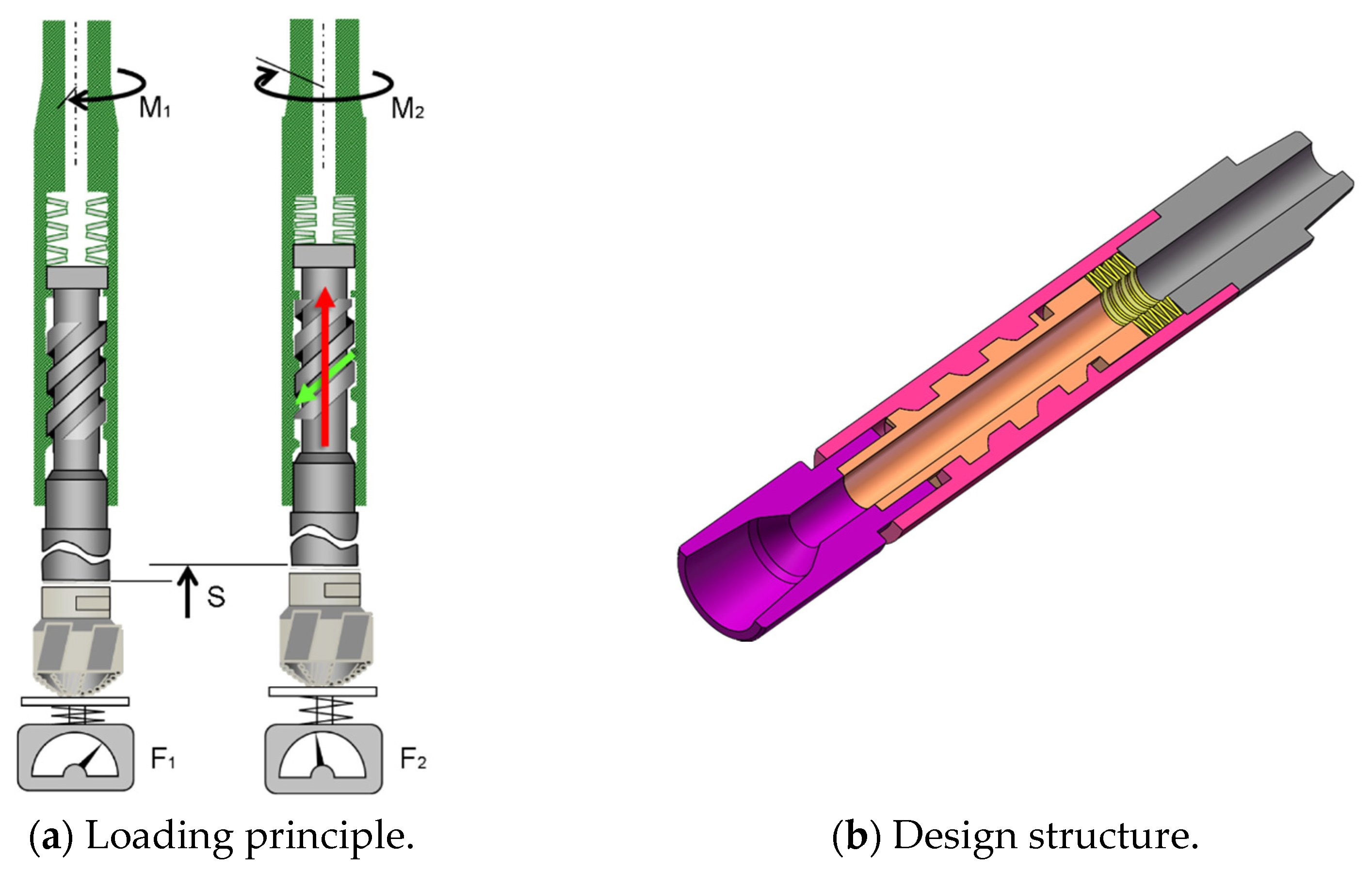
2.2. Loading Method for Adaptive Matching of Drilling Loads

There are two methods for downhole load adaptive adjustment, which indirectly regulate the cutting depth of a PDC cutter while intruding into bottomhole rock or reducing applied external loads during rock breaking.
Cutting depth control: By monitoring the axial invasion depth of the PDC drill bit into the bottomhole rock during rock breaking, when the cutting depth exceeds a predefined threshold, the magnitude of the applied axial force is automatically reduced by some amount. This reduction subsequently decreases the single-pass cutting depth.
External load control on cutters: During the process of rock breaking in the bottomhole with PDC drill bits, three-dimensional reaction forces are monitored. If the reaction force in the cutting direction surpasses a set threshold, the cutting speed of the PDC cutter gradually decreases, leading to a reduction in rock-breaking efficiency. At this stage, lowering the external axial force causes the single-penetration depth to decrease.
During drilling in strongly heterogeneous formations or soft–hard interbedded formations, there will be a high contacting force suffered in the PDC cutters of the drill bit, resulting in greater stress while cutting a piece of a large particle with certain high strength. Therefore, this paper proposes a kind of adaptive matching drilling load method based on the above second load adjustment method. The axial load acting on the PDC cutter (similar with the weight on bit, or WOB) can be adjusted automatically to release the contacting force of the drill bit by reducing the cutting depth in the bottomhole. Figure 1 shows the working principle and the 3D design structure of a kind of tool using a downhole load-adjusting method according to the loading states of the axial load.
Figure 1a indicates the loading principle of automatic downhole load adjustment. This mechanism operates as follows: when the drilling force exceeds a predefined threshold and leads to significant load or torque fluctuations in the process of rock breaking by the drill bit at the bottomhole, the spiral guide rod rotation device integrated within the tool will automatically activate. This action lifts the drill bit by a specified axial distance, thereby reducing both the cutting depth and the reaction force exerted on the drill bit.
A tool implementing this working principle was structurally designed as shown in Figure 1b, of which the detailed component configuration is presented in Figure 2. As can be seen in Figure 2, it consists primarily of a housing, upper connector (box), lower connector (pin), spiral guide rod, and disc spring assembly. Here, the terms “box” and “pin” are alternatively used to denote the upper and lower connectors, respectively.
The implementation of this tool enables automatic and prompt mitigation of the downhole load acting on the drill bit during drilling. This dynamic adjustment method can lead to a reduction in the contact force exerted by the PDC cutters integrated into the drill bit, thereby minimizing the risk of bottomhole drilling failures caused by excessive impact loading.

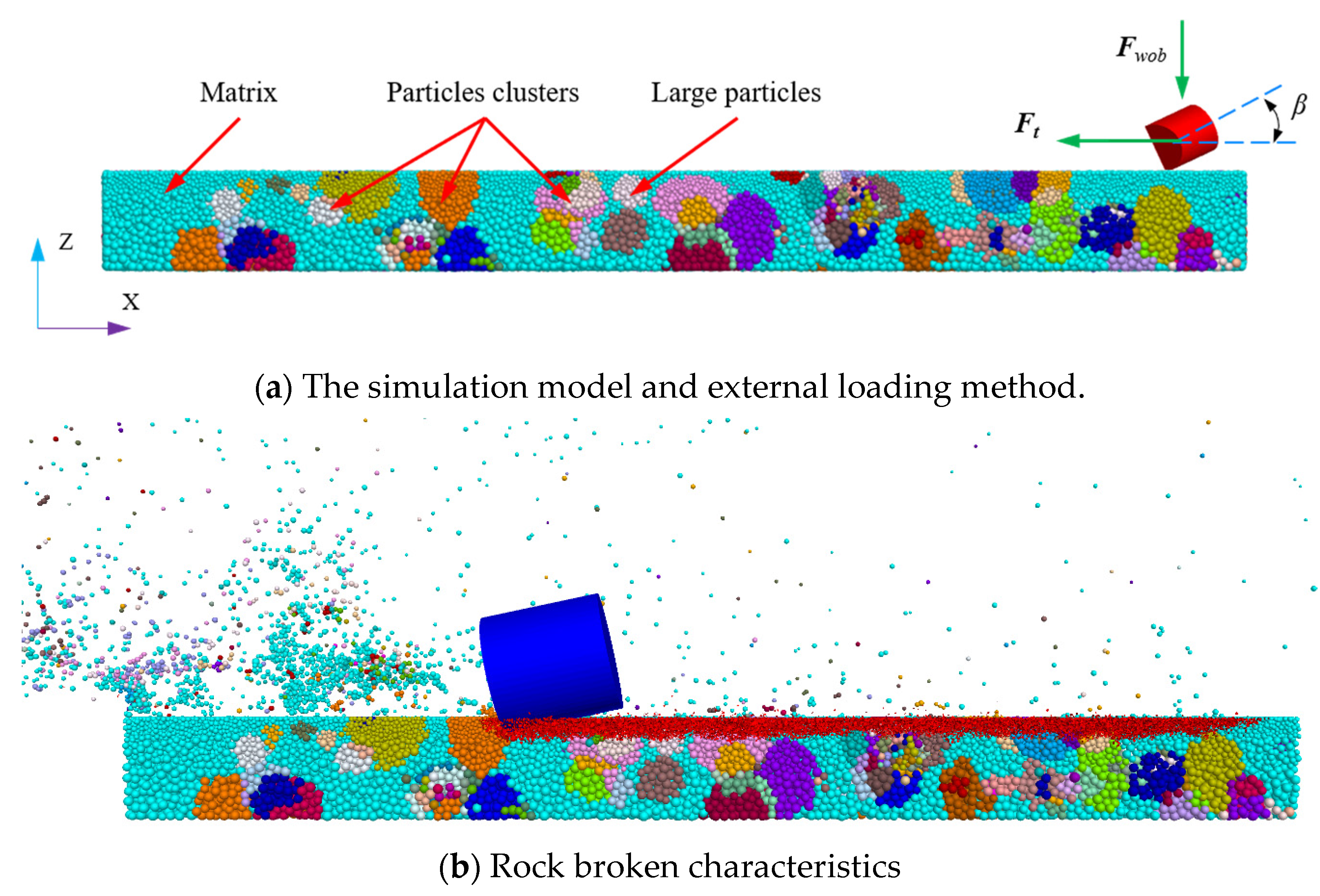
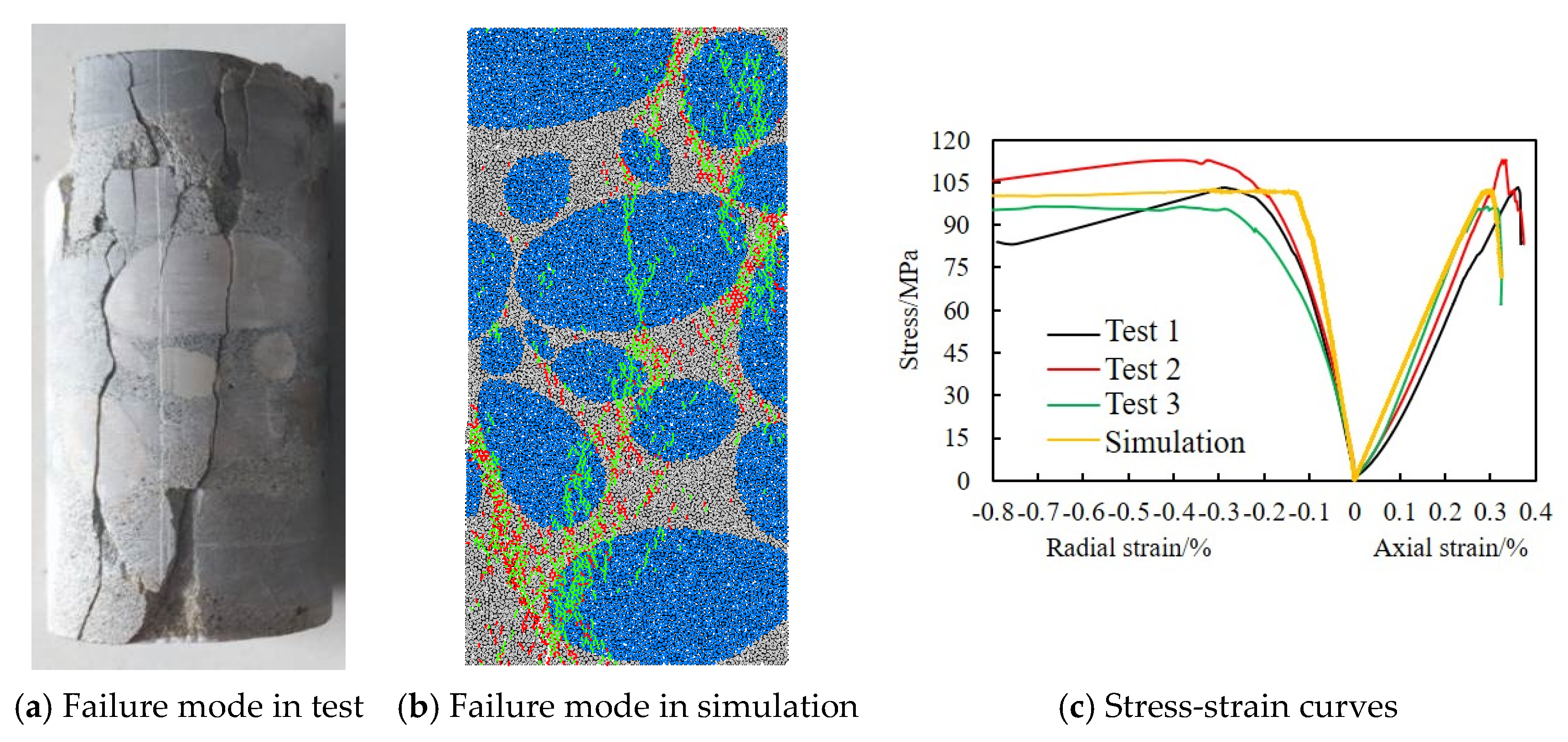
2.3. Modeling of the PDC Cutter Cutting Rock

To investigate the rock-breaking mechanism enabled by the proposed adaptive matching drilling load method in drilling operations, a discrete element method (DEM) numerical model was developed by means of the PFC3D platform, as shown in Figure 3. The radius of the particles ranges from 0.5 to 0.8 mm, and the total number of balls generated in the DEM model is 104313. The simulation framework incorporates a strongly heterogeneous rock, which is composed of a group of large-sized particles or particle clusters and the matrix. All of the large-sized particles or particle clusters are bonded by the matrix, with similar natural lithological characteristics.
The micromechanical parameters of the simulated rock and the contact interaction parameters between the PDC cutter and the rock are referenced from several pieces from the existing literature, specifically those by Wei, Luo, Gao, and Liu [20,21,22,23,24]. Table 1 summarizes the critical meso-parameters employed in the DEM model of the simulated heterogeneous rock, while Figure 4 demonstrates excellent agreement between experimental results and numerical predictions, thus validating the parameter selection process.
In the rock breaking simulating model, a PDC cutter with a diameter of 16 mm and a certain back forward angle β (15°) is established, as shown in Figure 3a. The axial load FWOB and drive force Ft will be applied to the PDC cutter to replicate downhole drilling conditions.
Under the action of axial load and drive force, the PDC cutter will execute rock cutting operations as schematically shown in Figure 3a. There are no restrictions for the displacement and motion of the PDC cutter in the X, Y, and Z directions, and real-time monitoring of the three-dimensional displacement, disp_x, disp_y and disp_z, and the reaction forces, Fx, Fy and Fz, acting on the PDC cutter, is enabled while simulating. According to the simulation results, the relationship between the displacement of the PDC cutter in the X direction (cutting direction) and the applied axial force is shown in Figure 5a, and the variation in the reaction force monitored in the PDC cutter and time while simulating are given in Figure 5b.
As shown in Figure 5, when the displacement in the X direction reached approximately 79.5 mm, the PDC cutter encountered a piece of a large particle, causing a significant reaction force and nearly halting the forward movement in the X direction. Owing to the adaptive matching of the axial load, when the incremental displacement disp_x fell below a predefined threshold, the axial load applied to the PDC cutter decreased proportionally. The reduction ratio in the adaptive method is defined as the load factor (donated as α) in this study, expressed mathematically as FWOB = α · FWOB0, where the FWOB0 indicates the initial applied axial force on the PDC cutter while simulating.
Since the increment in disp_x in this paper is small during each time step during simulation, there is a fluctuation in axial load within the range of 12~27.8 ms. It can also be seen that there is no displacement during that period, and the reaction force also oscillates synchronously.
The work power and the mechanical specific energy (MSE) can be used to evaluate the rock breaking efficiency of the PDC cutter. In line with the monitored displacement and reaction force of the PDC cutter based on the above simulation model, the work power can be calculated according to the following formula:
W = F x d x + F y dy + F z dz = F x i Δ x i + F y i Δ y i + F z i Δ z i
After simulation, the volume of rock broken can be counted in the software, and then the MSE can be obtained as follows:
MSE = F x d x + F y dy + F z dz V = F x i Δ x i + F y i Δ y i + F z i Δ z i V
where V indicates the volume of rock broken; Fx, Fy, and Fz are the detected reaction force, also named the cutting force; and dx, dy, dz, ∆x, ∆y and ∆z express the increment in the displacement in the x, y and z directions, respectively.

3. Results and Discussion

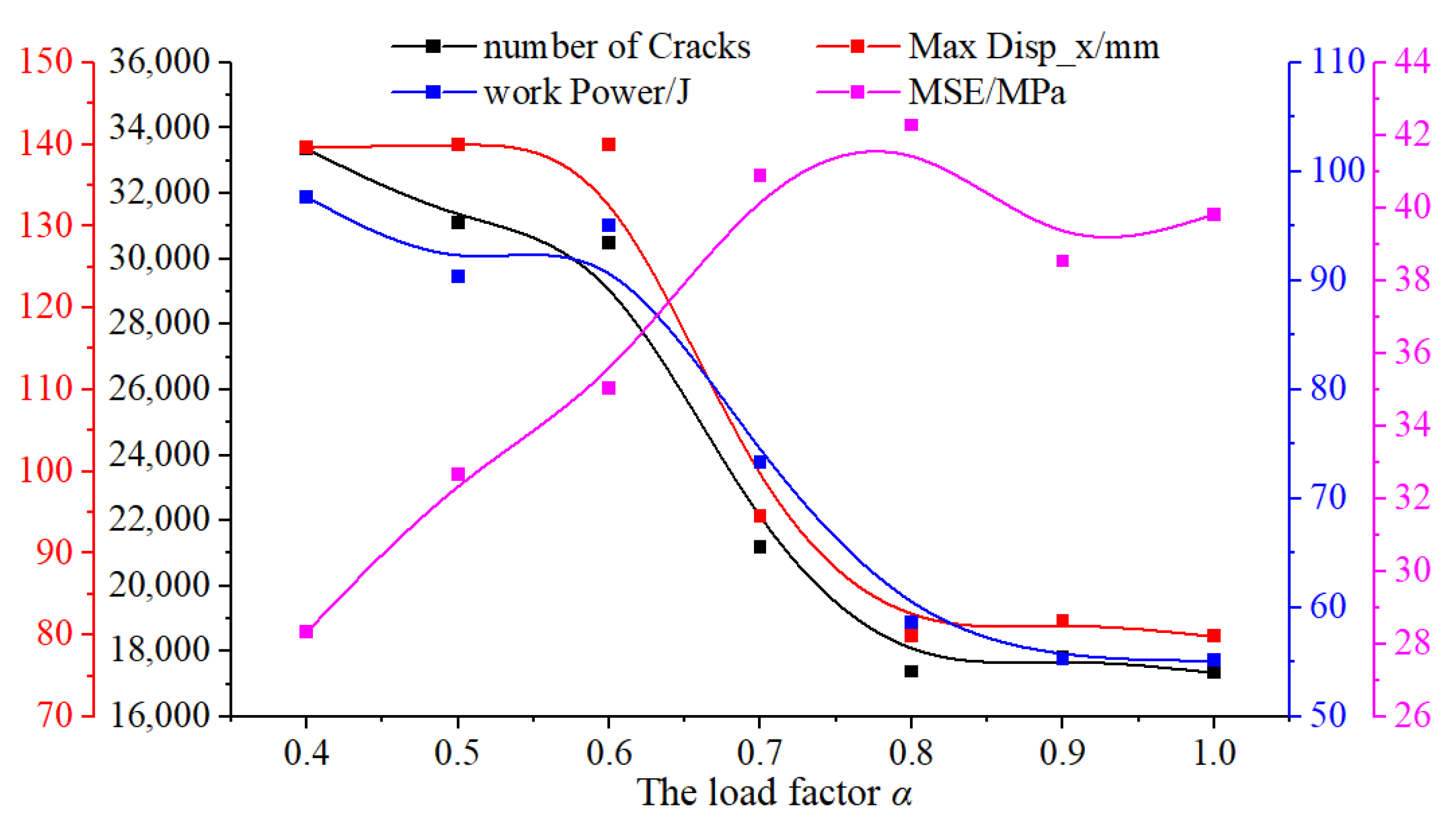
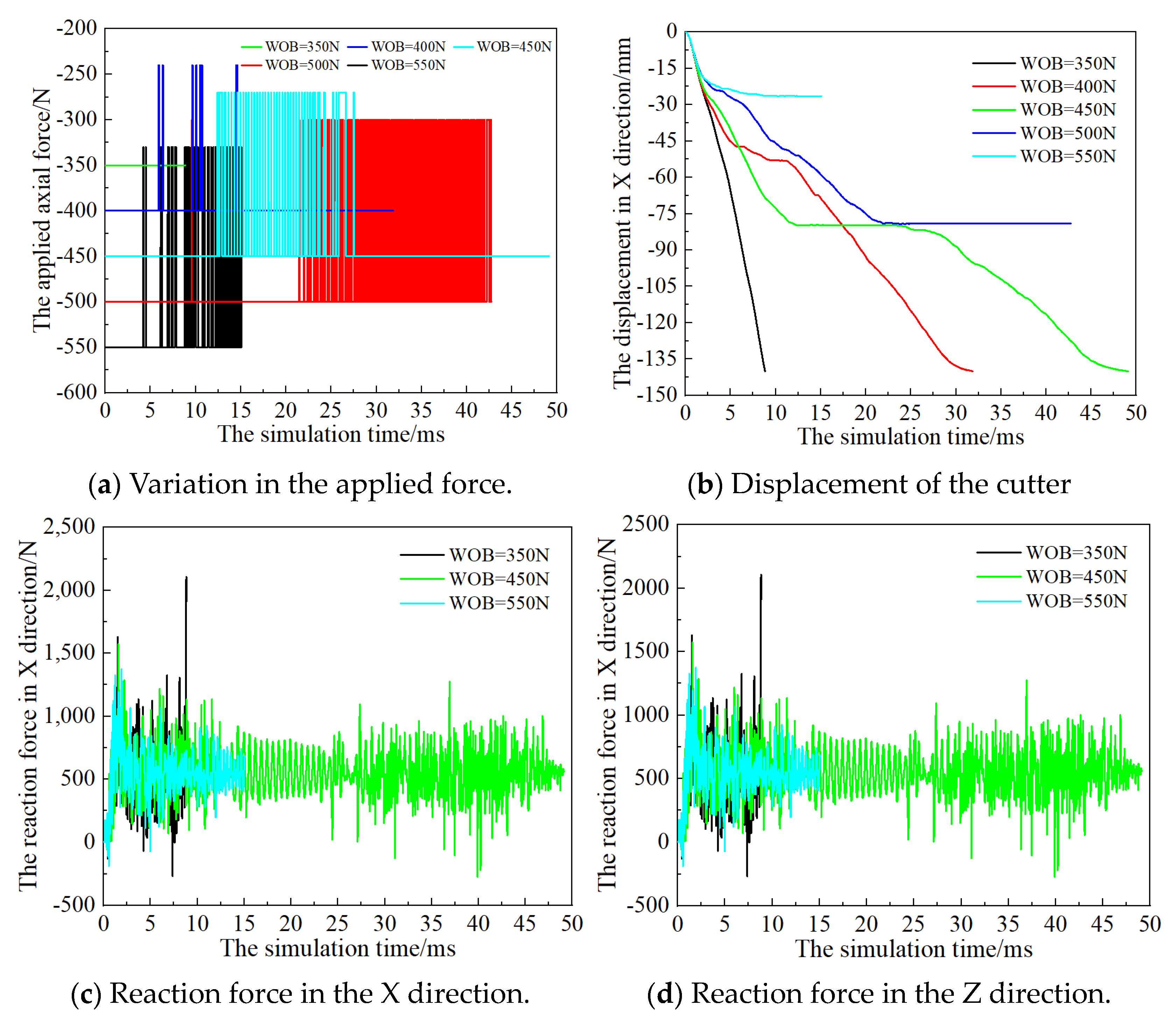
3.1. Effect of the Load Factor

The load factor (denoted α) in this study is defined as the proportion of the reduction degree of the applied axial force to the initial load. Under the action of different load factors ranging from 0.4 to 1.0, the corresponding drilling load manifested as the reaction force detected in the PDC cutter while drilling, and it exhibited distinct response patterns, as shown in Figure 6.
As shown in Figure 6, the curves of the displacement and its fluctuation, the applied force, the reaction force, and the number of cracks demonstrate significant differences in variation trends and growth patterns. In correlating Figure 5a and Figure 6a, it is evident that the displacement curves of the PDC cutter exhibit a tendency to oscillate while sticking. Moreover, the oscillation amplitude of the displacement curve in the X direction shows a strong inverse correlation with the load factor (α); smaller α values correspond to reduced oscillation amplitudes.
In addition, Figure 6a,b indicate that both the displacement and the motion curves are modulated by the load factor, achieving the designed maximum displacement, 140 mm. When the load factor exceeds 0.7, the PDC cutter will be stuck at a displacement of 94.5 mm.
As observed in Figure 6c,d, the applied axial load and the reaction force acting on the PDC cutter and their changing characteristics are significantly influenced by the load factor. While the factor is 0.7 or greater, the applied axial load varies greatly in the latter stage (after the checkpoint, 94.5 mm), but the motion curves and the displacement remain almost unchanged. The main reason for this phenomenon is that when the PDC cutter is stuck, the displacement will not increase continuously but the applied axial force will decrease proportionally based on the load factor set for the program.
Figure 6e,f present the number of cracks and their various types with the simulation time detected during the rock-breaking process. The cracks can be divided into tensile cracks and shear cracks, representing different failure modes of rock under the action of the PDC cutter. Figure 6e illustrates the number of total cracks, tensile cracks, and shear cracks with the simulation time while the load factor is 0.6, which show that the proportion of tensile cracks is 85.2–86.13%, indicating that the failure mode of the simulated rock is mainly tensile failure. Figure 6f shows the number of total cracks under different load factors, indicating that the changing characteristics and growth trends of the cracks show significant differences alongside the load factor, as well as similarities with the growth curves of displacement.
Figure 7 indicates the key characteristic parameters during rock breaking with the action of the PDC cutter, such as the total number of cracks, the maximum displacement in the X direction, the work power, and the MSE.
In view of Figure 7, we know that the number of total cracks, the maximum displacement, and the work power decrease with the increase in the load factor while MSE increases, opposing the trend in the work power. The displacement represents the extent to which the PDC cutter advances during rock breaking. The maximum value of the displacement in the X direction which was preset in the simulation program is 140 mm; the program will stop automatically when it reaches 140 mm. In another way, the higher the MSE, the more energy is consumed during the rock-breaking process. The more cracks that are generated during the rock-breaking process, the more complete the rock failure.
The simulation results demonstrate that the load factor exerts significant influence on both the kinematic characteristics of the PDC cutter and the rock fragmentation patterns, thereby directly affecting rock-breaking efficiency. However, the adaptive matching method of the loading strategy implemented via the spiral guide rod mechanism of the designed tool (seen in Figure 2) incurs additional downhole energy consumption in adjusting the drilling load. Notably, a smaller load factor corresponds to higher energy expenditure for dynamic adjustments. Through parametric optimization considering both rock-breaking efficiency and energy consumption, the optimal load factor of α = 0.6 is selected in this study.

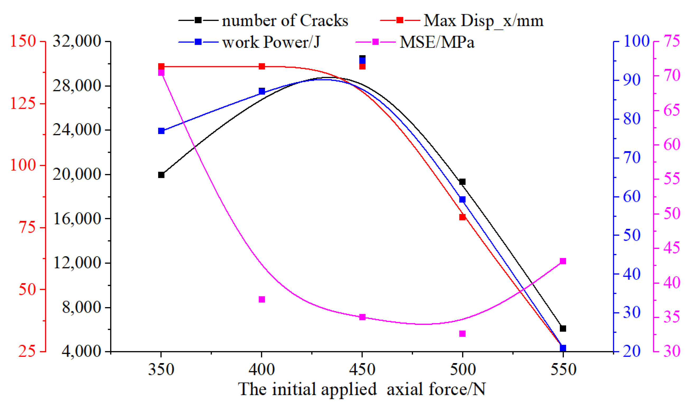
3.2. Effect of the Initial Axial Force

In this study, the initial axial force (equivalent to the weight on bit, or WOB, which acts on the PDC drill bit while drilling in bottomhole) is used to characterize the applied initial axial force, indicating the applied axial force at the beginning of the simulation. This parameter directly dictates the initial cutting depth and corresponding reaction force profile, thereby influencing both the cutting velocity and displacement progression. Figure 8 shows the results of the kinematic behavior and reaction force characteristics of the PDC cutter under varying initial axial forces, ranging from 350 N to 550 N, at a fixed load factor of 0.6. Additionally, Figure 9 presents the corresponding rock fragmentation characteristic parameters throughout the simulation period.
Under the condition of the same driven force acting on the PDC cutter, the variation frequency of the axial force and cutting displacement exhibited minor differences throughout the simulation period. Compared to an applied axial load of 400 N, the PDC cutter achieved greater displacement under an axial load of 600 N. This is because higher axial force increases the cutting depth during rock breaking, leading to elevated reaction force on the cutter. These amplified forces induce temporary acceleration followed by cutter seizure. Once seized, displacement progression halts while the applied axial load is dynamically adjusted.
As shown in Figure 8a,b, when the applied axial force (denoted WOB in the figure) reaches 550 N, the PDC cutter experiences minimal displacement and seizes earliest in both simulation time and displacement progression. Similarly, reaction forces in the X (cutting direction) and Z (axial direction) directions mirror the displacement trends. Specifically, Figure 8c,d reveal that upon cutter seizure, the X direction’s reaction force exhibits regular oscillatory behavior, whereas the axial reaction force fluctuates irregularly.
The PDC cutter could become stuck during simulation under the action of different initial axial forces, leading to a distinct rock fragmentation state and cutting displacement characteristics. Figure 9 demonstrates that the total number of cracks, the maximum displacement, and the work power monitored in the simulation process firstly increase and then decrease while increasing the initial axial force, whereas MSE exhibits the opposite tendency.
Specifically, when the initial axial force is below 450 N, the maximum displacement in the X direction reaches the programmed limit of 140 mm. At 450 N, both work power and the number of total cracks attain peak values, indicating optimal rock failure efficiency. A higher MSE corresponds to greater energy consumption, while more cracks signify more complete rock fragmentation. Figure 9 further reveals the minimum MSE occurs at an axial force of 500 N, though the maximum displacement remains below 140 mm at this load due to cutter seizure upon encountering large particles or clusters.
Based on the above parametric analysis, an initial axial force of 450 N acting on the PDC cutter was selected in this study for the subsequent simulation. This kind of setting ensures complete simulated rock destruction while minimizing energy consumption and maximizing crack generation during the rock-breaking simulation.

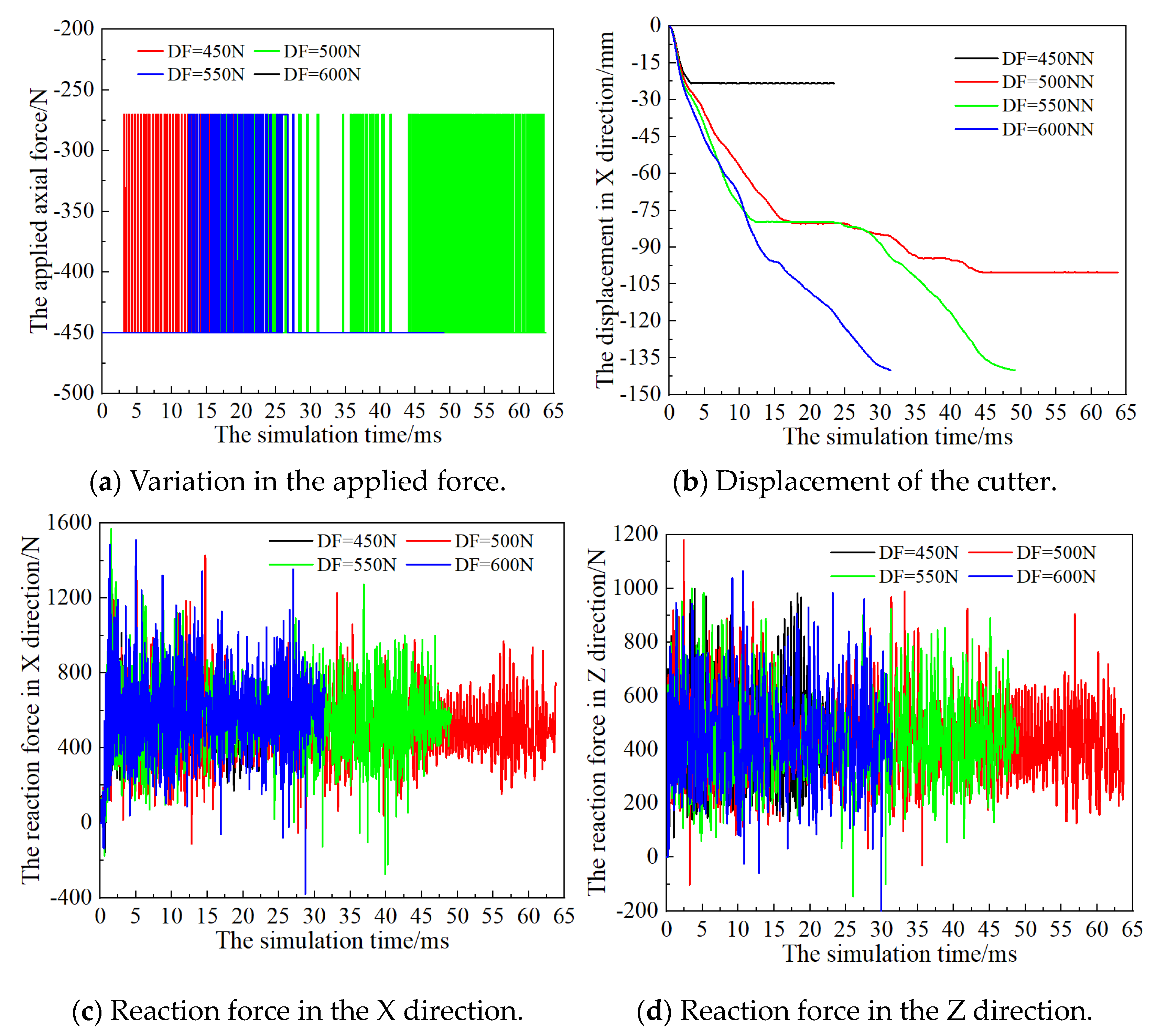
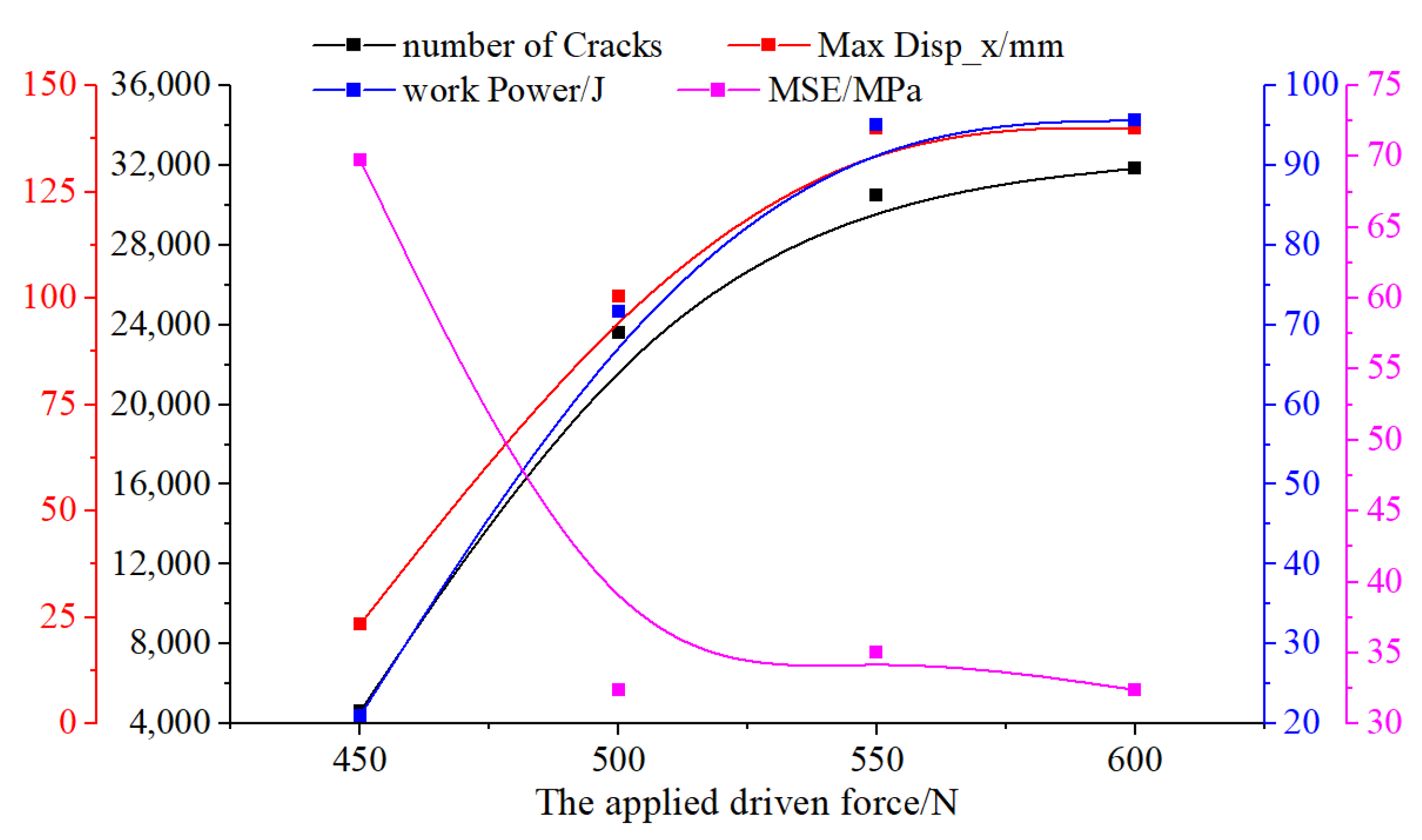
3.3. Effect of the Driven Force

In this study, the driven force represents the cutting force applied to the PDC cutter in the X direction, serving as the primary energy source for rock fragmentation. Figure 10 presents the simulation results on the PDC cutter’s kinematic behavior and reaction force characteristics under varying driven forces (450 N to 600 N) during the entire simulation period. These simulations were conducted with a fixed initial axial force of 450 N and a load factor of 0.6. Corresponding rock fragmentation parameters across different driven forces are provided in Figure 11.
With the initial axial force held constant, maintaining a consistent initial cutting depth, the cutting displacement, axial force variation patterns, and reaction forces on the PDC cutter exhibited significant differences under the action of different driven forces. As shown in Figure 10a, smaller driven forces increased the likelihood of cutter seizure during rock breaking. At a driven force of 500 N, two distinct seizure stages occurred (as seen in Figure 10b), resulting in maximum X direction displacement falling short of the programmed 140 mm. Conversely, when the driven force was set to be 550 N, a single seizure event was induced, while the driven force of 600 N enabled smooth cutter progression without seizure. With a driven force of 600 N and the applied axial force kept constant at 450 N, the adaptive load-matching mechanism was rendered inactive.
According to Figure 11 above, the number of total cracks generated, the maximum displacement, and the work power increase during the rock-breaking process with the increase in the driven force, whereas MSE exhibits the opposite tendency though its growth rate gradually decelerates. When the driven force increases from 550 N to 600 N, the PDC cutter achieves the programmed displacement limitation, but increments in total cracks and the work power become negligible. This is because higher driven force enables rapid completion of the simulation without cutter seizure, resulting in elevated cutting velocities that drive increased work power and energy consumption under a constant axial load acting on PDC cutter.
Consequently, driven force applied to the PDC cutter—or equivalently, torque to the PDC bit during drilling in the bottomhole—should be controlled within an optimal range. Combining the results in Figure 10 and Figure 11, a driven force of 550 N is recommended for this study’s rock-breaking process. This setting balances rock fragmentation efficiency, energy consumption, and cutter stability while activating the adaptive load-matching mechanism.

4. Conclusions

(1)
This study proposes an adaptive matching method of drilling load acting on the PDC drill bit during the process of rock breaking in a bottomhole. The working principle and adjustment mechanism of this method are elaborated upon in detail, complemented by the detailed structural design of a purpose-built tool implementing this adaptive load control.
(2)
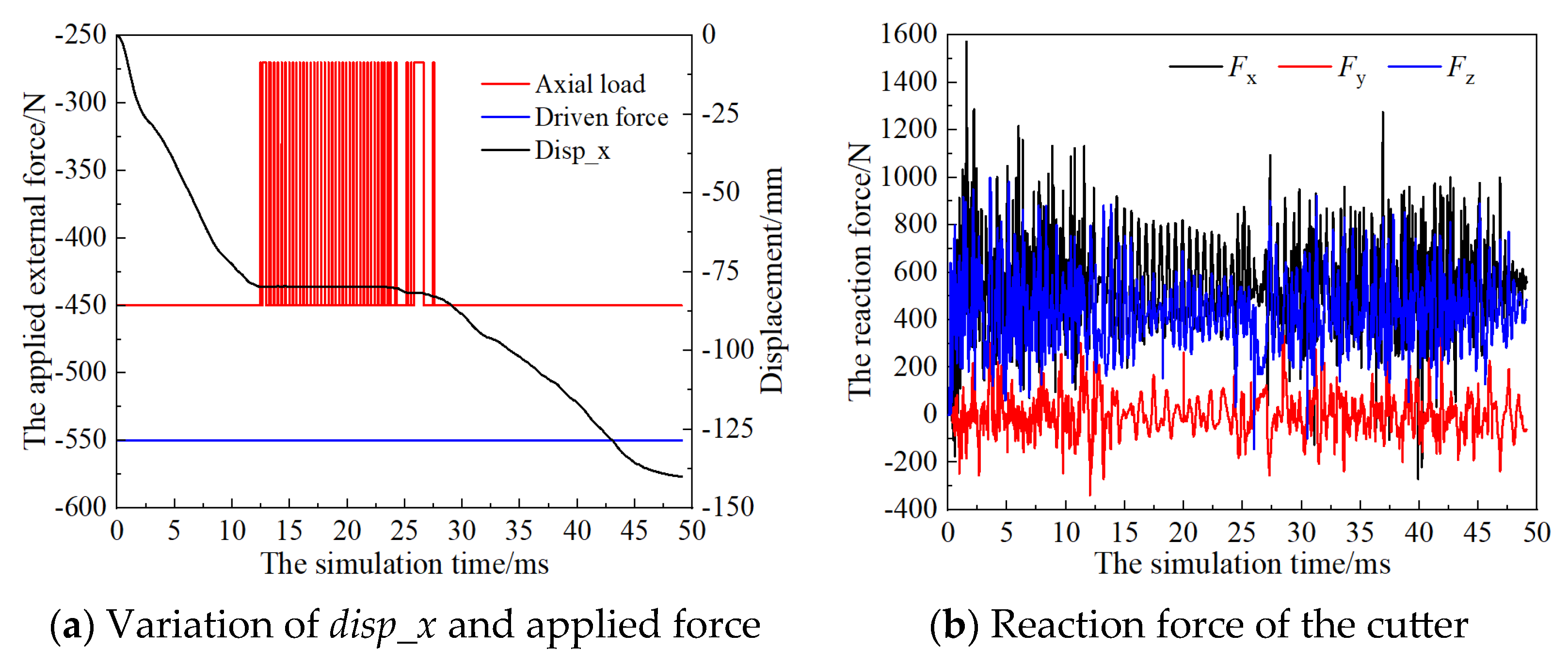
A kind of simulation model of rock breaking under the action of a PDC cutter based on the discrete element method (DEM) is established, incorporating the proposed adaptive matching method of drilling load to dynamically adjust applied axial force according to the reaction force monitored in the cutter. This simulation framework enables systematic investigation of the rock-breaking mechanism under adaptive load conditions.
(3)
The influential factors of load factor, initial axial force, and driven force on the kinematics and rock fragmentation behavior are clarified based on the proposed method. The use of the proposed method of this kind of tool can systematically decrease the reaction force in the cutting direction, while axial reaction force exhibits non-uniform fluctuations. The total crack count inversely correlates with MSE, and the tensile cracks account for 85% of total failures, consistent with the simulated rock’s tensile-dominated failure mode. The cracks generated a decrease while increasing the load factor, which increases linearly with the driven force and follows a parabolic trend with the initial axial force acting on the PDC cutter.
(4)
The proposed adaptive matching method of drilling load strategy improves the mechanics of PDC cutter–rock contact, thereby enhancing drilling efficiency and the working life through reduced drillstring vibration and reaction force mitigation. This innovation offers a viable solution for optimizing penetration rates in highly heterogeneous formations or soft–hard interbedded formations by dynamically balancing cutting loads and energy consumption.

Author Contributions

Conceptualization, H.H., L.Z. and K.W.; methodology, H.H., G.J., F.S., L.Z. and K.W.; software, L.Z. and K.W.; validation, H.H., G.J. and F.S.; formal analysis, G.J., F.S. and L.Z.; investigation, H.H., L.Z. and K.W.; resources, H.H., G.J. and F.S.; data curation, H.H., G.J. and F.S.; writing—original draft preparation, L.Z. and K.W.; writing—review and editing, H.H., G.J. and K.W.; visualization, F.S. and L.Z.; supervision, H.H., G.J. and L.Z.; project administration, H.H., G.J., F.S. and K.W.; funding acquisition, K.W. All authors have read and agreed to the published version of the manuscript.

Funding

The work of this study was funded by the Foundation of National Engineering Research Center of Oil & Gas Drilling and Completion Technology (No.: NERCDCT202312); the CNPC Programs for Subordinate Institution (No.: CPET2022-10S); the CNPC Major Science and Technology Project “Development of Key Engineering Technologies and Equipment for Ultra-deep Drilling” (No.: 2023ZZ20); and the CNPC Programs for Science and Technology Development “Research on Key Technologies and Equipment for drilling and Completion of ultra-deep Oil and Gas Resources” (No.: 2022ZG06).

Institutional Review Board Statement

Not applicable.

Informed Consent Statement

Not applicable.

Data Availability Statement

The data presented in this study are available on request from the corresponding author. The data are not publicly available due to the project research hereto being incomplete.

Conflicts of Interest

Authors Huaigang Hu, Guodong Ji, Fangyuan Shao were employed by CNPC Engineering Technology R&D Company Limited. The remaining authors declare that the research was conducted in the absence of any commercial or financial relationships that could be construed as a potential conflict of interest.

References

  1. Wang, H.; Ge, Y.; Lin, S. Technologies in deep and ultra-deep well drilling: Present status, challenges and future trend in the 13th Five-Year Plan period (2016–2020). Nat. Gas. Ind. B 2017, 4, 319–326. [Google Scholar] [CrossRef]
  2. Caicedo, H.; Calhoun, W.; Ewy, R. Unique ROP predictor using bit-specific coefficient of sliding friction and mechanical efficiency as a function of confined compressive strength impacts drilling performance. In Proceedings of the SPE/IADC Drilling Conference, Amsterdam, The Netherlands, 23–25 February 2005; Society of Petroleum Engineers: Calgary, AB, Canada, 2005. [Google Scholar]
  3. Jain, J.R.; Ricks, G.; Baxter, B.; Vempati, C.; Peters, V.; Bilen, J.-M.; Spencer, R.; Stibbe, H. A Step Change in Drill Bit Technology with Self-Adjusting PDC Bits. In Proceedings of the SPE/IADC Drilling Conference and Exhibition, Fort Worth, TX, USA, 1–3 March 2016; SPE-178815. Society of Petroleum Engineers: Calgary, AB, Canada, 2016. [Google Scholar]
  4. Kenneth, E.; Russell, S.C. Innovative Ability to Change Drilling Responses of a PDC Bit at the Rig Site Using Interchangeable Depth of Cut Control Features. In Proceedings of the SPE/IADC Drilling Conference and Exhibition, Fort Worth, TX, USA, 1–3 March 2016; SPE-178808. Society of Petroleum Engineers: Calgary, AB, Canada, 2016. [Google Scholar]
  5. Si, N.; Deng, H.; Li, J.; Pi, G. Self-adjusting PDC bit of Baker Hughes. Fault-Block Oil Gas Field 2017, 24, 125–130. [Google Scholar]
  6. Hu, H.; Huang, H.; Wang, H. New Progress and Development Trends of PDC Bits in China and Abroad. China Pet. Mach. 2024, 52, 1–10. [Google Scholar]
  7. Hu, H. Research on Influence Factors of Rock-Breaking Efficiency and Physical Design of Wob Self-Adjusting PDC Bit; China University of Petroleum: Qingdao, China, 2021. [Google Scholar]
  8. Hu, H.; Guan, Z.; Zhang, B.; Xu, Y.; Liu, Y.; Wang, B. Structure design of weight-on-bit self-adjusting PDC bit based on stress field analysis and experiment evaluation. J. Pet. Sci. Eng. 2021, 196, 107692. [Google Scholar] [CrossRef]
  9. Hu, H.; Guan, Z.; Wang, B.; Liang, D.; Sun, M.; Wang, X.; Chen, W. Weight-on-Bit Self-Adjusting Dual-Diameter Bit Leads a Step Change in Drilling Bit Technology. In Proceedings of the International Petroleum Technology Conference, Beijing, China, 26–28 March 2019; Society of Petroleum Engineers: Calgary, AB, Canada, 2019. [Google Scholar]
  10. Jain, J.R.; Ricks, G.; Ledgerwood, L.W.; Phillips, A. Mitigating Drilling Dysfunctions and Enhancing Performance with Self-Adjusting Bit Technology: Analytical and Experimental Case Studies. In Proceedings of the SPE/IADC Drilling Conference and Exhibition, The Hague, The Netherlands, 14–16 March 2017; SPE-184736-MS. Society of Petroleum Engineers: Calgary, AB, Canada, 2017. [Google Scholar]
  11. Bai, B.; Zeng, Y.; Lu, X.; Zhang, J.; Tao, L. An ROP Improvement Technology Based on Adaptive Matching Between the Rock-Breaking Energy of Bits and Rock Features. Pet. Drill. Tech. 2023, 51, 30–36. [Google Scholar]
  12. Selnes, K.S.; Clemmensen, C.C.; Reimers, N. Drilling Difficult Formations Efficiently with the Use of an Antistall Tool. In Proceedings of the IADC/SPE Drilling Conference, Orlando, FL, USA, 4–6 March 2008. [Google Scholar]
  13. Dagestad, V.; Mykkeltvedt, M.; Eide, K.; Reimers, N. First field results for extended-reach ct-drilling tool. In Proceedings of the SPE/ICoTA Coiled Tubing and Well Intervention Conference and Exhibition, Woodlands, TX, USA, 4–5 April 2006. [Google Scholar]
  14. Cundall, P.A.; Strack, O.D.L. A discrete numerical model for granular assemblies. Geotechnique 1979, 29, 47–65. [Google Scholar] [CrossRef]
  15. Cundall, P.A.; Hart, R.D. Numerical modelling of discontinua. Eng. Comput. 1992, 9, 101–113. [Google Scholar] [CrossRef]
  16. Potyondy, D.O. The bonded-particle model as a tool for rock mechanics research and application: Current trends and future directions. Geosyst. Eng. 2015, 18, 1–28. [Google Scholar] [CrossRef]
  17. Itasca Consulting Group. Particle Flow Code in Two Dimensions; Itasca Consulting Group, Inc.: Minneapolis, MN, USA, 1999. [Google Scholar]
  18. Lei, S.T.; Kaitkay, P. Distinct Element Modeling of Rock Cutting under Hydrostatic Pressure. Key Eng. Mater. 2003, 250, 110–117. [Google Scholar] [CrossRef]
  19. Itasca Consulting Group, Inc. PFC (Particle Flow Code in 2 and 3 Dimensions); Version 5.0; Itasca Consulting Group, Inc.: Minneapolis, MN, USA, 2016. [Google Scholar]
  20. Wei, J.; Liao, H.; Huang, B.; Li, N.; Liang, H.; Zhou, B.; Zhang, Q.; Chen, L.; Feng, H. Effect of the random distribution of gravel particles on the mechanical behaviors of conglomerate. Arab. J. Geosci. 2023, 16, 485. [Google Scholar] [CrossRef]
  21. Luo, S.; Ge, H.; Wang, J.; Zhou, W.; Shen, Y.; Liu, P.; Liu, J. Numerical simulation study on the crack propagation of conglomerate. R. Soc. Open Sci. 2021, 8, 202178. [Google Scholar] [CrossRef] [PubMed]
  22. Liu, D.; Li, J.; Gao, D.; Guo, H.; Lian, W.; Yang, H.; Gao, R. Analysis on Rock Breaking Mechanism and Adaptability of PDC Bit in Conglomerate Formation. China Pet. Mach. 2023, 51, 51–67. [Google Scholar]
  23. Liu, X.; Zou, D.; Chen, Y.; Huang, Y.; Wang, Q. Analysis of PDC cutter cutting broken conglomerate based on the discrete element method. Energy Sci. Eng. 2022, 10, 3580–3591. [Google Scholar] [CrossRef]
  24. Yang, H.; Deng, Q.; Ye, B.; Liu, J.; Huang, A. Simulation on Microscopic Damage of PDC Cutter During Conglomerate Cutting. China Pet. Mach. 2024, 52, 1–10. [Google Scholar]
Figure 1. Loading principle and design structure of the adaptive matching tool.
Applsci 15 04320 g001
Figure 2. The main components of the designed tool using adaptive matching method.
Applsci 15 04320 g002
Figure 3. The numerical model of a PDC cutter cutting strongly heterogeneous rock.
Applsci 15 04320 g003
Figure 4. Comparison of experimental and numerical simulation results.
Applsci 15 04320 g004
Figure 5. The simulation results of a PDC cutter cutting rock.
Applsci 15 04320 g005
Figure 6. Motion and reaction force of the PDC cutter under different load factors.
Applsci 15 04320 g006
Figure 7. Rock breaking characteristics under different load factors.
Applsci 15 04320 g007
Figure 8. Motion and reaction force of the PDC cutter under different initial WOBs.
Applsci 15 04320 g008
Figure 9. Rock breaking characteristics under different initial WOBs.
Applsci 15 04320 g009
Figure 10. Motion and reaction force of the PDC cutter under different driven forces.
Applsci 15 04320 g010
Figure 11. Rock breaking characteristics under different driven forces.
Applsci 15 04320 g011
Table 1. The meso-parameters of the simulated heterogeneous rock.
DescriptionParameterMatrixParticlesBond
Ball density/kg·m−3 ρ 25002875/
Ball–ball contact modulus/GPaEc11.425.212.6
Ball stiffness ratiokn/ks2.211.520.76
Parallel bond Young’s modulus/GPa E c ¯ 11.425.212.6
Particle contact’s normal to shear stiffness ratio k n ¯ / k s ¯ 2.211.520.76
Parallel bond normal strength/MPa σ c ¯ 31.145.422.7
Parallel bond cohesion/MPa c ¯ 31.145.422.7
Parallel bond frictional angle/° φ ¯ 384924.5
Ball friction coefficient μ 0.310.240.12
Disclaimer/Publisher’s Note: The statements, opinions and data contained in all publications are solely those of the individual author(s) and contributor(s) and not of MDPI and/or the editor(s). MDPI and/or the editor(s) disclaim responsibility for any injury to people or property resulting from any ideas, methods, instructions or products referred to in the content.

