Article

Wear Prediction and Mechanism Study of Tunnel Boring Machine Disc Cutter Breaking in Hard–Soft Rock Considering Thermal Effect

by
Xiongfei Lyu
1,
Youliang Chen
1,*,
Shaoming Liao
2 and
Tomas Manuel Fernandez-Steeger
3
1
Department of Civil Engineering, School of Environment and Architecture, University of Shanghai for Science and Technology, Shanghai 200093, China
2
Department of Geotechnical Engineering, Tongji University, Shanghai 200092, China
3
Department of Engineering Geology, Institute of Applied Geosciences, Technische Universität Berlin, 10587 Berlin, Germany
*
Author to whom correspondence should be addressed.
Appl. Sci. 2025, 15(8), 4183; https://doi.org/10.3390/app15084183
Submission received: 9 February 2025 / Revised: 30 March 2025 / Accepted: 8 April 2025 / Published: 10 April 2025

Abstract

:
The TBM disc cutter cuts soft–hard composite strata during shield construction, and the cutter–rock cutting process generates high temperatures and severe wear. In this research, different strength types of rocks are taken as objects to analyse the interacting rock-breaking force and cutter motion model. The effects of rock properties on wear are investigated, and the cutter ring wear mechanism and damage types are discussed. Combined with the thermal stress theory of elastomer and the abrasive wear theory, a prediction model for cutter wear depth and wear mass is proposed. The results of the study show that the type of wear is dominated by abrasive wear, with the highest probability of uniform wear occurring in cutting hard rock. Hard rock is the most abrasive to the steel material of the cutter ring, and the percentage of abrasive wear decreases for cutting soft–hard composite strata. The amount of abrasive wear is negatively correlated with the hardness of the cutter ring. The rock damage patterns are different when cutting soft and hard rocks, and the wear areas are located at the bottom and sides of the cutter ring, respectively. Considering the thermal effect, the depth of wear for cutting hard rock has a power function relationship with the installation radius, which is closer to the actual value. The theoretical models are generally lower than the actual measured values. The wear prediction model is useful for determining the replacement interval of the cutter and improving the rock-breaking efficiency.

1. Introduction

Tunnel shield engineering has facilitated the study of TBM cutter wear. The diversity of geological formations and the frictional heat of cutting have created many construction challenges in shield tunnelling operations. In composite strata of soft–hard rock, there is a large variability of stratigraphic properties in the excavation surface, and the high-strength, highly abrasive rock and soil bodies are widely distributed. The working environment of a shield disc cutter is complex, and the cutting mode and temperature affect the cutter wear. Excessive wear of the cutters in long-distance shield construction is prone to damage, reducing construction efficiency and quality.
Scholars have carried out a great deal of research on cutter wear, including analyses of the wear process and wear mechanism, focusing on the rock-breaking force model and the establishment of cutter wear prediction theory. A series of studies on the wear characteristics of soft and hard rocks and cutter–rock wear mechanisms were carried out; for example, Jin, D. et al. [1] investigated the rock abrasion resistance and strength characteristics of rock specimens from 267 different rock types. Based on the collected data, the uncertainty characteristics of rock abrasion resistance and TBM operating parameters are summarised. Macias, F. J. et al. [2,3] from the Norwegian University of Science and Technology (NTNU) proposed predictive modelling for hard-rock TBMs. Based on engineering geological and experimental test data, hard-rock tunnel boring cutter performance prediction and tool life assessment are carried out. Zhang, X. et al. [4] conducted rock wear tests on disc cutters of six hardnesses and three typical rocks using a cutting machine (LCM). The wear mechanism and wear depth were analysed using laser microscopy. Plinninger, R. J. et al. [5] considered various shield conditions, such as rock mass scale factors, mixed unstable rock formations, etc., for hard-rock mechanical tunnelling, which have a significant impact on the actual wear condition. Deliormanlı, A. H. et al. [6] presented strength tests in uniaxial compression (UCS) and straight shear (DSS) that affect CAI values. Fifteen different marble specimens were tested, and a strong correlation was found between CAI values, strength and wear test values. Elbaz, K., Shen, S. L., et al. [7,8] analysed the factors affecting cutter wear and the performance of shield intervals in Line 9 of the Guangzhou Metro in China. Tunnelling in soft and hard composite stratum conditions leads to increased cutter wear. Sun, Z. et al. [9] reduced the test cutter to 1/10 of the actual cutter and produced a composite tool wear test device model to study TBM tool life and tool wear prediction. Balci, C. et al. [10] compared the cutting efficiency of V-shaped disc cutters in rocks of different strengths. Considering medium-strength and non-abrasive rocks of the formation, the V-shaped cutter is very effective in practice.
Other scholars are carrying out research on cutting force patterns and wear prediction models: Karami, M., Rostami, J., et al. [11] focus on commonly used predictive disc wear life and empirical models, as well as conducting comparative studies. Their study discusses the effect of TBM specifications, operating conditions and rock abrasiveness on wear. Frenzel, C., Käsling, H., et al. [12] systematically present the influence of geological and technological factors and analyse the optimisation of operational parameters in TBMs cutting hard rock based on field experience, e.g., adjusting the rotational speed or thrust of the cutter to reduce the wear of the cutter. Lin, L. et al. [13] investigated the wear characteristics of TBM cutter–rock interaction and conducted a series of wear test studies to obtain the mass loss, vertical load, temperature field, wear mechanism and change rule of a disc cutting ring. Ren, D. J. et al. [14] studied cutter wear in composite strata engineering based on field observation data. The friction energy, working condition and geological conditions during cutting are analysed, and a prediction model is proposed. Yu, H., Tao, J., et al. [15] consider the shortcomings of existing disc cutter wear prediction models, and a new calculation method and prediction model of disc cutter wear based on hard-rock cutting parameters is proposed. Ren, D. J., Shen, S. L., et al. [16] investigated transverse continuous wear of disc cutters under quartz sand soft-grinding conditions to assess the energy consumed during friction and wear. Wang, L., Li, H., et al. [17] used theoretical and experimental studies of wear changes in cutting hard rock to analyse the wear mechanism of cutter ring surface materials. A new theoretical model of wear evolution is proposed.
This study investigates the inter-relationships between soft and hard composite strata characteristics, excavation parameters and the amount of wear. Geng, Q. et al. [18] simulated four different rock cutting models considering the rock crushing process, as well as rock tensile and compressive strengths, and compared them with the results of rock cutting tests. It discusses the cutter–rock interaction and wear mechanism in the excavation face of different strength types of strata [19] and analyses the influence of abrasive characteristics on the amount of wear. It also considers the influence of the rock-breaking load model and cutting temperature thermal effect [20]. Based on the elastomer thermal stress theory and the abrasive wear model, the prediction theory of the depth and quality of cutter wear for cutting hard and soft rocks is proposed. Predicting and evaluating the cutter wear will help to reduce the risk and cost of opening the warehouse for inspection and changing the cutter, improve the efficiency of shield tunnelling and ensure the safety of shield construction.

2. Rock Composition and Wear Characteristics of Composite Strata

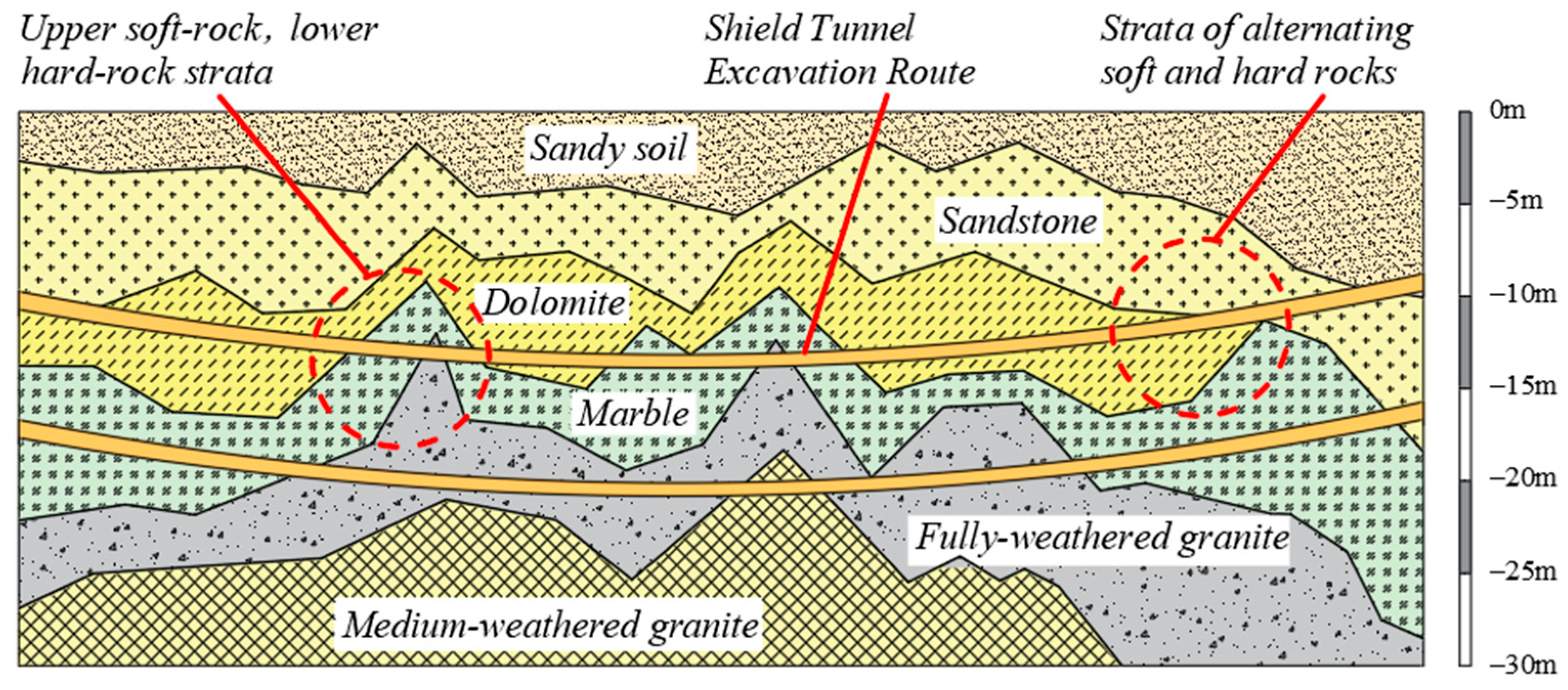
2.1. Composition of Hard and Soft Strata

In the excavation vertical plane or boring direction, the underground tunnel shield project often encountered the soft and hard composite strata with large changes in the nature of the rock layer [21]. The nature of the rock–soil body has obvious non-uniformity, the upper part of the tunnel section is often distributed with loose and soft soil layers, and the lower part of the distribution is hard-rock strata, resulting in alternating stratigraphic types. Rocks or cemented layers with a uniaxial compressive strength of 20 MPa or more are present during shield tunnelling and need to be broken using a shield cutter. The contact force situation of the cutter is complex, and the unbalanced force will lead to violent vibration of the cutter ring, and the cutter ring as well as the spindle can be easily damaged. Considering the stability of the rock cutting process, analytical calculations were carried out using an ideal contact model. Different geotechnical strength types affect the configuration of the shield machine cutter. Multiple factors such as the cutting force condition, geotechnical properties, wear mechanism [22] and cutter ring material are also important factors in the wear of the cutter ring.
As in the case of the Guangzhou–Shenzhen Intercity Railway located in China, the project selected for analysis is located in the shield section of the metro near the Shenzhen airport. There are two shield construction tunnels on the left and right lines within the section, and the total length of the shield tunnels is about 2760 m. The strata within the tunnel construction area mainly include sandy soil, sandstone, dolomite, marble, fully weathered granite, moderately weathered granite and so on. The main distribution of the above strata is shown in Figure 1.

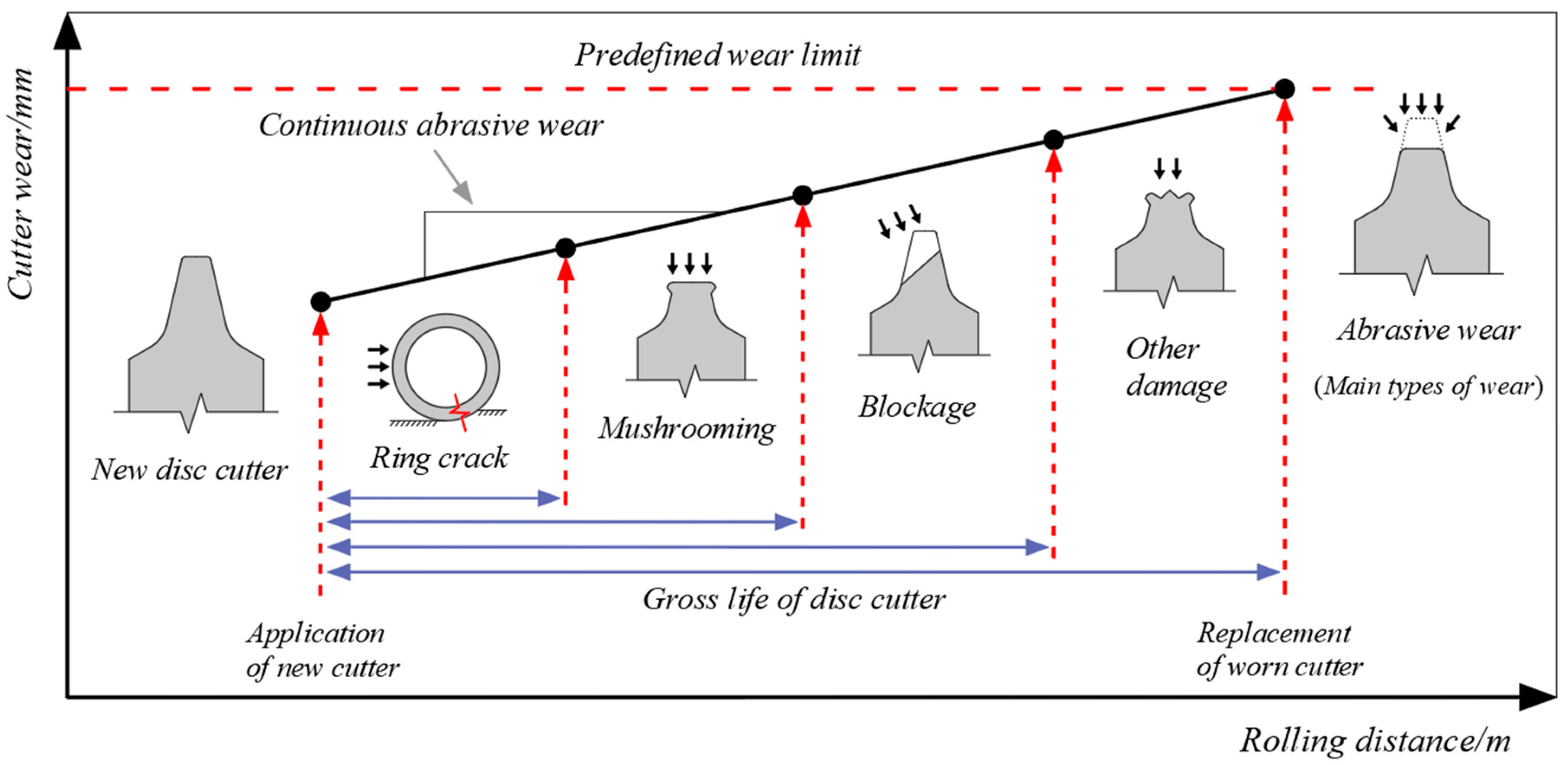
2.2. Wear Types and Wear Phenomena of Disc Cutter

There is contact friction during the cutter–rock cutting process, which produces different wear phenomena. In order to analyse the mechanism of cutter wear and its influencing factors, scholars have sorted out and classified different types of wear. Macias, F. J. et al. studied a shield construction project for a water tunnel in Norway and collected data on the wear of cutters over 7 km of shield excavation [2]. The excavation surface stratigraphy is distributed with hard rocks, mainly granite, quartzite and marble, with strengths of up to 264 MPa and quartz contents of up to 61%. The statistical data of the cutter wear type are shown in Figure 2; the proportion of abrasive wear is 71%, and the proportion of cutter ring fracture is 18%. Cutting hard rock is more wear intensive, with the total number of cutter replacements amounting to 1068, of which 575 were of the even-wear type, accounting for 54% of the total wear.
In a 500 m long tunnel project in Austria, the cross-section was unevenly distributed between soft and hard rocks [5], and statistical data on the type of cutter wear are shown in Figure 3. The percentage of abrasive wear in this tunnel section decreases to only about 49% for uneven strata and blocky rock conditions and 41% for cutter ring fractures. The decrease in the percentage of abrasive wear for cutting composite strata indicates that wear in soft rock requires a different wear calculation method. Cutting soft rock tends to lead to cutter ring sharpening, and cutting inhomogeneous formations leads to vibration damage of the cutter and fracture. Plinninger, R. J.’s study showed that even wear was the most probable type of cutter wear, with homogeneous or abrasive wear dominating. This was followed by bias wear and cutter ring chipping. Low wear has relatively little effect on the rock-breaking capacity. This study focuses on the type of uniform wear of the cutter ring. Wear areas on the outer edge and sides are analysed, and a wear prediction model is constructed.
The degree of cutter wear often varies during the life cycle. Clarifying the wear failure and replacement cycle of the cutter can optimally improve the rock-breaking performance and cutting efficiency of the TBM [23]. The distribution of cutter life and wear is shown in Figure 4; the wear increases gradually with the wear distance, and the cutting distance affects wear degree and cutter life [3]. The probability of even wear is high, and there is a correlation between different factors.
Wear occurs on the surface of the material, and the hardness of the alloy material of H13 steel reflects the characteristics of the cutter ring, which is an important factor affecting the wear of the cutter. Hardness reflects the abrasiveness of harder materials on softer materials. Analysis and determination with a hardness index is helpful to describe the degree of wear and calculate the amount of wear. Zhang, X. et al. [4] and Lin, L. et al. [13] investigated the relationship between the hardness of the cutter ring material, the average wear depth and the mass loss. Figure 5 shows the variation in wear with hardness. It indicates that there is a negative correlation between the hardness of the cutter ring material and the average wear amount [24]. The greater the hardness of the cutter ring, the lower the wear of cutting soft and hard rocks.
The wear state of the cutter ring is affected by the abrasiveness of the rock and the degree of penetration, reflecting the rock characteristics of the shield excavation face. Frenzel, C., et al. investigated the relationship between penetration, external thrust and ultimate torque [12]. The given three-cutter cutting operating curves are shown in Figure 6. In low-strength rocks, the cutter–rock cutting produces maximum penetration but low thrust. In high-strength rocks, the cutter reaches maximum thrust but lower penetration. The maximum penetration is limited by the external thrust and torque, and the reduction in penetration can significantly reduce the wear of the cutter ring, showing the effect of thrust and penetration on wear in different-strength rocks [25,26].

2.3. Rock Abrasion Resistance and Rock Property Variability

Describing the variability of geotechnical parameters is conducive to clarifying the cutter ring wear mechanism. The abrasive index (CAI) and strength parameters of the wear state parameters were counted. The characteristics of four different types of rock samples—sandstone, dolomite, marble and granite—are analysed. As shown in Figure 7, the soft-rock abrasiveness is relatively high, and the large friction area of cutter–rock contact increases the amount of wear. Medium-strength rocks have less abrasive wear, and high-strength granite has the highest abrasiveness. Since crushing high-strength hard rock requires increased external thrust, the extrusion friction leads to higher wear.
Statistics show that the frequency distribution of abrasive indicators of some typical rocks changes with the CAI values. As shown in Figure 8a–d, the probability density function (PDF) of the distribution form of the CAI values for four types of rocks and their fitted curves is determined. Extensive validation was carried out by Ching and Phoon et al. [27], and it was found that rock abrasiveness does not follow the regular distribution form. Most of the abrasive indicator frequencies show a normal distribution, proving that the law has practical physical significance.

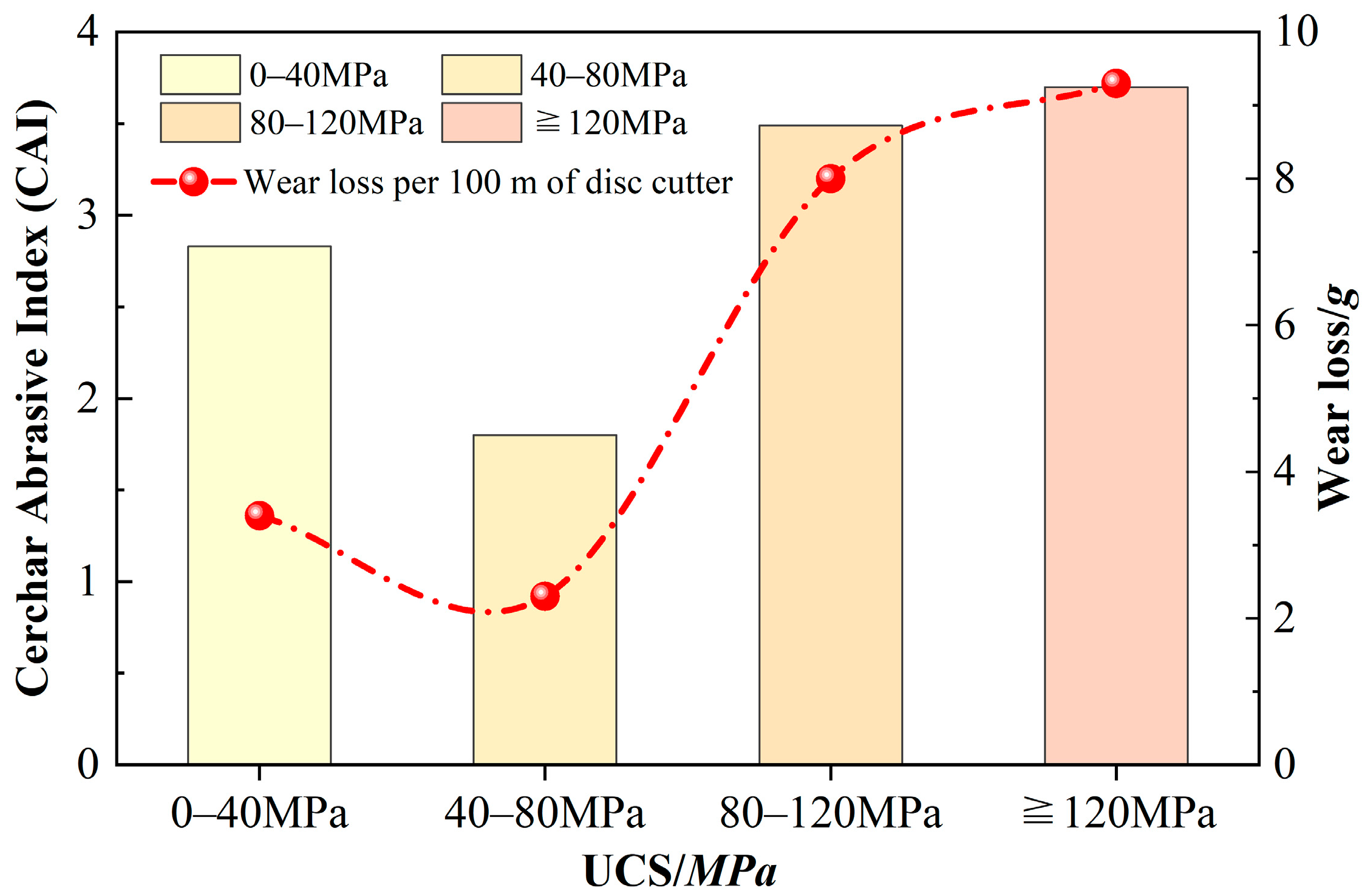
2.4. Relationship Between Rock Strength and Wear

Different rock particles have different amounts of plastic cutting of alloy surface materials. Most of the uniaxial compressive strength (UCS) index is currently used as an evaluation criterion. Based on the abrasion test data of Deliormanlı, A. H. and Al-Ameen, S. I. [28], a data-fitting method was used. The particle abrasiveness index (CAI) was investigated as a function of rock strength for common harder rocks, such as granite and marble, with strengths in the range of 40–160 MPa. The fitting and comparison results show that in the high-strength hard-rock cutting process, wear is mainly at the radial outer edge of the cutter ring, and the overall positive correlation is shown in Figure 9.
The type of composite strata strength affects the wear of the cutter [29]. In order to investigate the role of rock strength, a project case is selected, as shown in Figure 10, with a strength of 0–200 MPa and a cutting distance of 100 m. The analysis shows the cutting and wear condition of the rock samples, and Sun, Z. et al. summarise the relationship between the rock CAI and the wear mass loss of the cutter with the rock strength [6,28]. The increase in the strength of soft and hard rocks makes the CAI and wear of hard-rock cutting gradually increase. However, the wear mass is also higher in pure soft rock, indicating that the cutting pattern in soft rock is different from that in hard rock. The outer edge of the cutter is in full contact and friction with the soft rock, and its wear location is mainly in the area on both sides of the cutter head.

3. Force Model and Relative Motion Analysis of Cutter

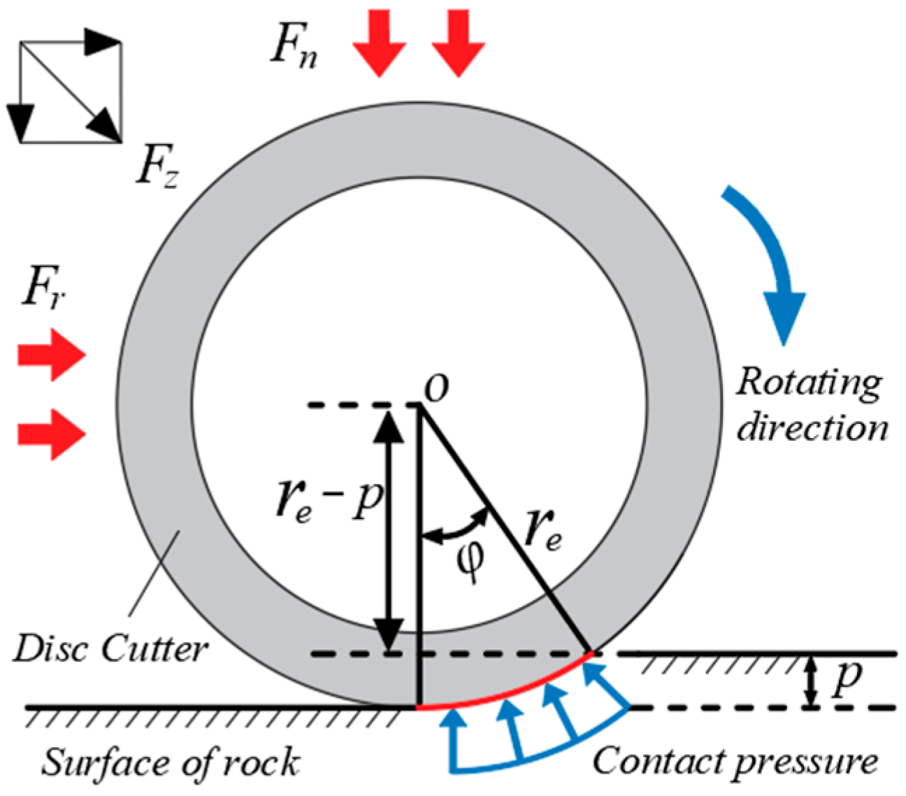
3.1. Rock-Breaking Force Pattern of the Cutter

Most of the research on cutter wear focuses on wear factor analysis, as well as force modelling. The soft and hard rock conditions determine the cutter force state. The external vertical force and rolling force make the cutter rotate and cut and create contact with the rock body at the bottom and two sides. Different stratigraphic transition interfaces will intensify the impact and wear, and the rock-breaking force pattern and the cutter motion directly affect the wear condition of the cutter ring [30].
Comprehensive prediction theory of rock-breaking force is based on the semi-theoretical and semi-empirical theory Colorado School of Mines (CSM) force model. According to the rock-breaking theory and wear prediction model proposed by scholars at home and abroad, thermal stress and soft–hard composite stratum conditions are considered. We explore the cutter wear mechanism and prediction model under the action of temperature effect [31].
The force state and motion mode of the cutter breaking process are analysed, as shown in Figure 11. The cutter is rotated in the direction of the rotation axis under the external loads F r and F n and cuts the rock. The penetration of the cutter ring is p , the material is uniform, and the friction of the cutter shaft and body is ignored. The cutter ring model is simplified as a thin, hollow disc model, and the cutter is subjected to vertical force and rolling force, whose combined force F s is directed towards the centre of the disc. Based on the CSM theoretical rock-breaking force model, the mathematical relationship between cutting parameters is established. The cutter combined force F z is:
F z = C φ U r e 1 + γ F P
The contact angle φ of cutter-rock is expressed as:
φ = arccos r e p r e  
The distribution pressure F P in the crushing zone at the edge of the cutter is:
F P = S σ c 2 σ t φ U r e   1 3
where F p is the distributed pressure in the cutter–rock contact crushing zone.
The vertical load F n and tangential load F r applied to the disc cutter are:
F n = F z cos φ 2 = cos φ 2 C φ U r e 1 + γ S σ c 2 σ t φ U r e   1 3 F r = F z sin φ 2 = sin φ 2 C φ U r e 1 + γ S σ c 2 σ t φ U r e   1 3        
where F n is the vertical force, F r is the rolling force, F z is the combined force, r e is the outer radius of the cutter, φ is the contact angle between the cutter and rock; U is the width of the cutter edge; σ c is the compressive strength of the rock; σ t is the tensile strength of the rock; γ is the coefficient of distribution of the cutter edge pressure, which takes a value of 0.1; S is the distance between cutters, where S = 75   m m ; and C is a dimensionless coefficient, where C = 2.12 .

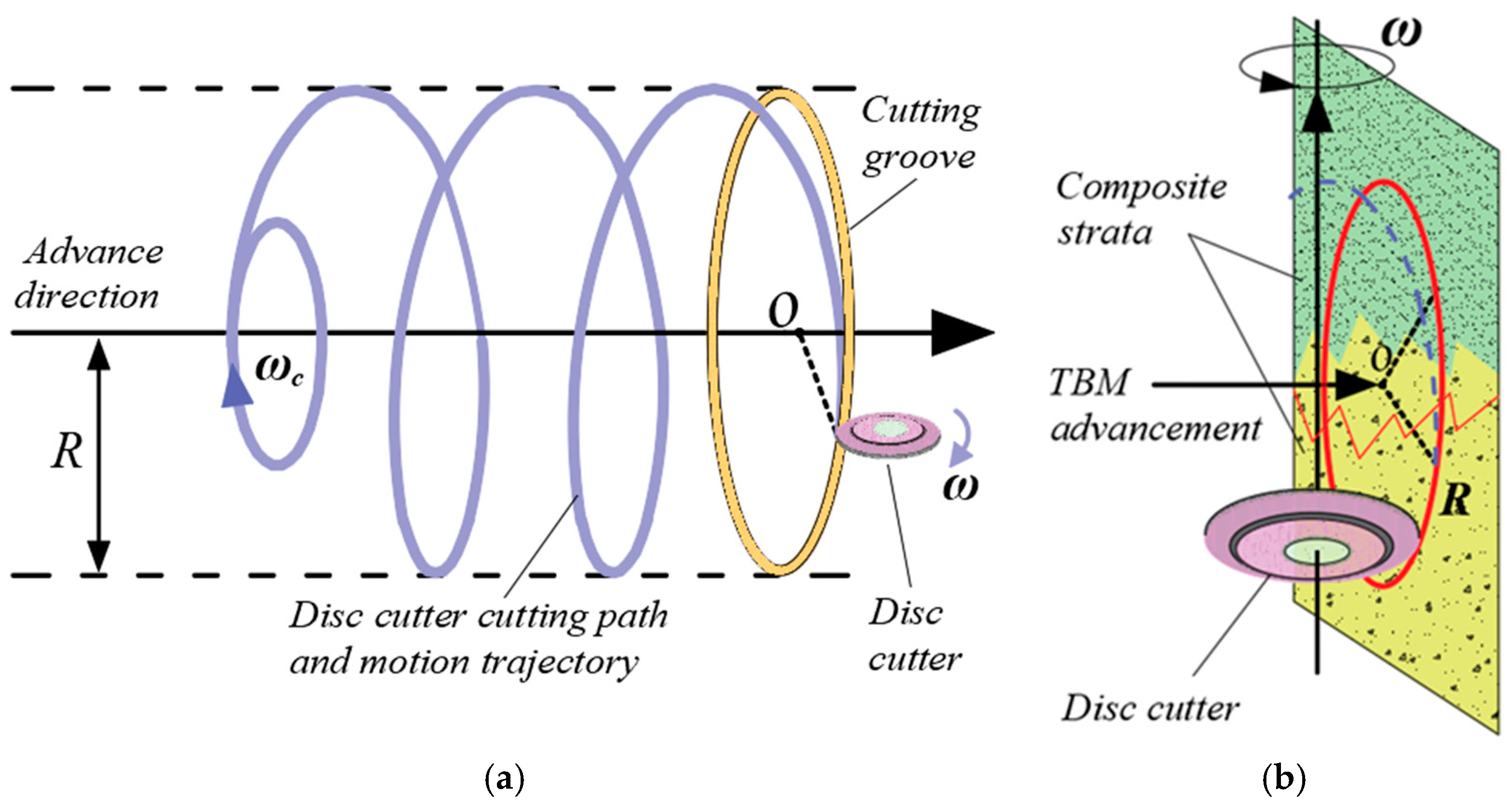
3.2. Analysis of Relative Motion

Cutter–rock relative sliding is a necessary condition for wear. According to the plastic removal mechanism of cutter–rock friction, the wear calculation must consider the cutter movement mode. Ideally, the cutter rotates with the shield disc and rotates around the cutter axis. The relative sliding distance between the cutter and the rock is not equal to the length of its absolute trajectory.
The cutter cutting path trajectory is a cylindrical helix [19]. We analyse the movement trajectory of the cutter with an installation radius of R and calculate the sliding cutting distance. The length of the actual trajectory is L , and the relative sliding cutting distance is L m . The cutter cutting path is simplified, the complex spiral cutting path is simplified to a straight line, the cutting trajectory is shown in Figure 12, and the cutting distance length is expressed as:
L = ω R τ    
where ω is the angular velocity of the cutter rotation motion; R is the cutter radius; and τ is the cutting time.

4. Cutter Wear Mechanism and Calculation Model Considering Thermal Effect

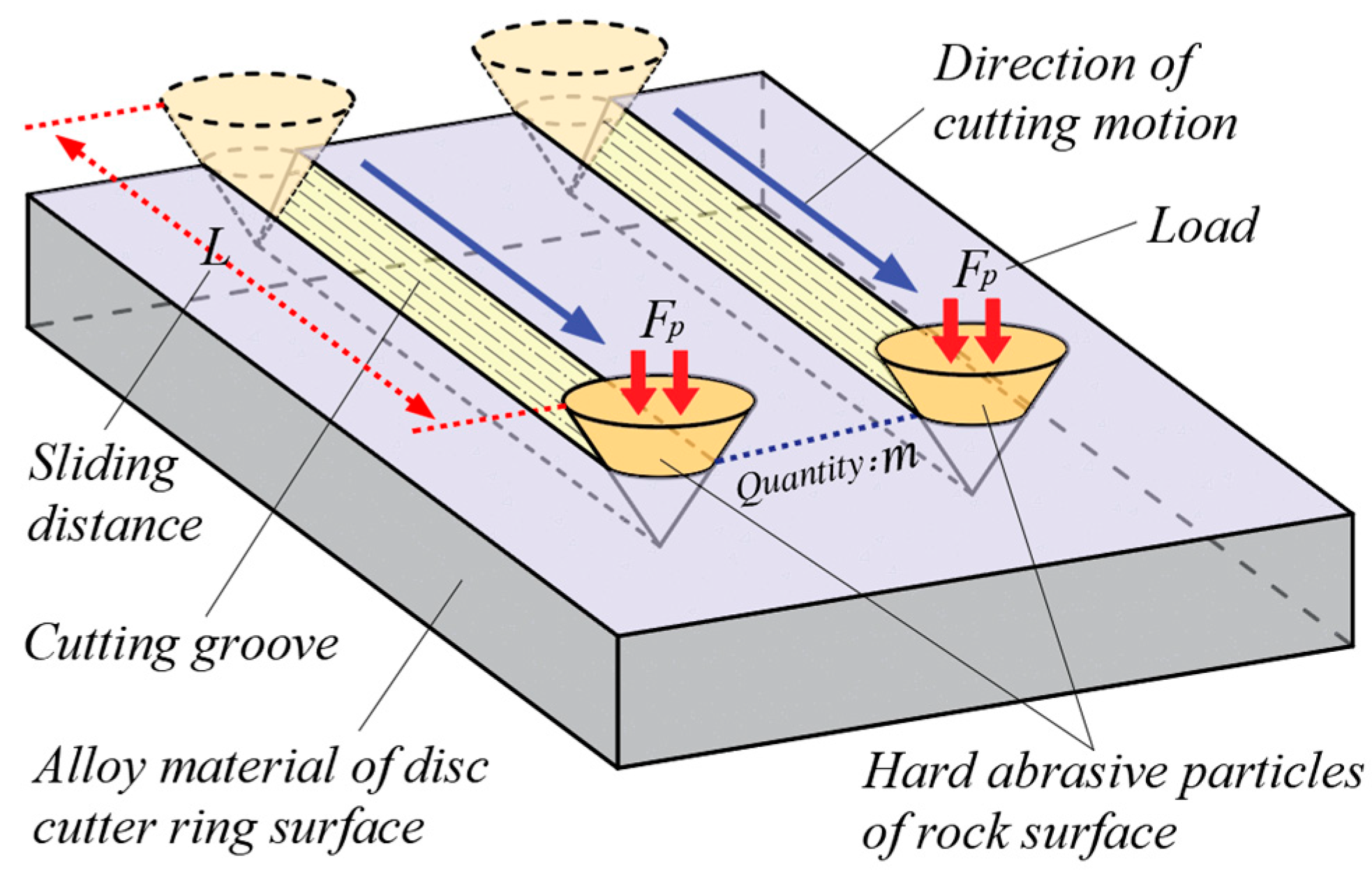
4.1. Abrasive Wear Mechanism and Archard’s Wear Law

The actual wear process is the result of the combined action of many different forms of wear. The essence of wear is the loss of material from the surface of the alloy material under cutting loads. The majority of the geotechnical material on the tunnelling face contains some types of mineral particles, such as quartz and abrasive particles. Based on tribological theory, a simplified cutting model of shield cutter wear was developed to quantify abrasive wear and calculate the amount of cutter ring wear [22,32]. Scholar Hutchings [22] unified and simplified a large number of irregularly shaped microscopic abrasive particles into a cone model and obtained the abrasive wear calculation model shown in Figure 13 and Figure 14.
According to the plastic cutting theory, conical grains move on a relatively soft cutter surface. Assuming that the abrasive grains are subjected to a normal load F P , the m abrasive grain load is F m . The volume of abrasive marks removed plastically from the cutter surface is V , the half angle of the conical grain model is β , and the depth of abrasive cutting is h P . The relative sliding distance of the cutter–rock is L .
The rock grit is harder than the cutter ring alloy material, and the normal load presses the cone grit into the surface of the softer material. Relative sliding causes the surface to undergo micro-plastic cutting removal. Friction and abrasive extrusion act to plough cut wear abrasions, forming grooved wear marks. Relevant statistical studies have shown that plastic removal of abrasive wear accounts for approximately 82.9% of total wear and is the main form of wear.
Macro-volumetric wear volume is determined by the form of micro-wear. Scholars’ studies on wear mechanisms use the wear volume as an evaluation criterion. According to Archard’s wear law, the material wear volume is independent of the sliding rate and shows a linear relationship with both the contact squeeze load as well as the sliding distance, expressed as:
V = K F L H  
where V is the volumetric wear of the cutter ring per unit sliding distance; F is the external contact load; H is the hardness of the cutter alloy surface material; and K is the dimensionless material wear coefficient.

4.2. Calculation of Radial Thermal Stresses on the Cutter Ring

The wear prediction model is established, and the radial thermal stress of the cutter ring is calculated by considering the soft and hard composite strata with thermal effect conditions. According to the thermal stress theory of elastomer, the cutter ring is simplified to a two-dimensional model without considering the thickness change, σ z = 0 and the stress–displacement in the radial and annular directions is obtained as:
σ t = E ( 1 + μ ) ( 1 μ ) d u d r + E μ ( 1 + μ ) ( 1 μ ) u r E α 1 μ t σ φ = E ( 1 + μ ) ( 1 μ ) u r + E μ ( 1 + μ ) ( 1 μ ) d u d r E α 1 μ t      
According to the force balance equation of the cutter ring:
d σ t d t + σ t σ φ t = 0                           ( a ) d σ z d z = 0                                                                 ( b )      
The cutter radius is known for the determined parameters r i , r e The radial integral of the disc cutter ring is calculated to obtain the thermal stress constants, denoted as C 1 , C 2 . Combined with the theory of heat transfer, calculations were carried out using the calculus method. The temperature field is constant, and the radial thermal stress expressions for cutting hard rock and soft rock are obtained separately:
σ t 1 = C 1 E α r 2 + F n 2 p tan α r 2 ( r p ) 2                                                                                             ( a ) σ t 2 = C 2 E α ( 1 μ ) r 2 + F n r 2 2 μ r 2 r i 2 1 + r 3 r e + r 3 r i 3 1 μ r e + r i r 2 + r e 2 r i 2 A ( r e 2 r i 2 )                           ( b )      

4.3. Wear Calculation for Cutting Hard Rock

Cutting hard and soft rocks over long distances has different wear patterns. It is necessary to analyse the cutting wear mechanism of different types of rocks separately. For hard-rock cutting, the wear that mainly occurs is abrasive wear, and the surface of the cutter is ploughed and embedded with a large number of tiny rock mineral particles. The cutter–rock extrusion cutting causes brittle damage to the hard rock, resulting in uniform wear of the cutter ring [33,34]. The wear location is at the bottom of the outer edge of the cutter ring. The CSM rock-breaking model was applied, and the hard-rock cutting model is shown in Figure 15.
The abrasive grains are simplified to a cone as:
A = π a 2                             a = h p tan β                  
where A is the projected area of the pressed-in portion of the conical particle, a is the radius of the pressed-in portion, h p is the depth of the pressed-in portion, and β is the half-angle of the cone.
In microscopic wear model, the abrasive grains move over material surface, ploughing the grooves, and the normal load of the n abrasive grains is expressed as:
F p = n σ s π h p 2   t a n 2 β
where σ s is the compressive yield limit of the material, and F p is the load applied to each abrasive grain.
The volume of abrasion when a single abrasive grain moves a unit distance is a h p . The distance travelled by an abrasive grain is dl, and the volume of material removed is:
d V = h p 2   tan β d l
Defining the wear volume produced per unit displacement as the wear degree d V / d l , the wear volume Q produced by motion of n abrasive grains is:
Q = n d V d l
Associating Equations (11)–(13) yields the volumetric wear:
Q = F p π σ s tan β  
The sliding distance is L s , and the volumetric wear of all conical particles on the cutter surface V is:
V = n d V d l L s = F p L s π σ s tan β  
The cutter rotates around the axis to cut, and the amount of wear lost on the outer edge surface is equal to the amount of wear removed by the plasticity of the abrasive grains. The cutting distance is the relative sliding distance. The cross-section of the wear model is shown in Figure 16a,b.
According to the wear volume balance, the wear volume is equal to the total volume of surface particles lost due to friction. The expression for the predicted volumetric wear V of the cutter is:
V = ( U L m p + h tan θ ) 2 π R  
where p is the depth of penetration, L m is the advancement distance of the cutter, U is the width of the cutting edge, h is the depth of wear, θ is the angle of the cutting edge on one side of the cutter head, and R is the mounting radius of the cutter.
The volumetric wear of the cutter ring increases with the cutting distance, and the wear depth h is expressed as:
h = ( V 2 π R tan θ U L m p tan θ )
The friction force is mainly the crushing pressure at the bottom of the cutter. Substituting the hard wear amount and external load expression (3) into Equation (17) gives us:
h = L s 10 2 2 π 2 R σ s tan θ tan β S σ c 2 σ t φ U r e   1 3 U L m p tan θ  
A purely rolling cutter does not do work and has no wear. Frontal wear of the cutter is mainly generated by relative sliding friction. The sliding friction distance is:
L s = ε L
The average slip ratio of a cutter cutting in soft and hard rocks can be expressed as:
ε = 1 ω r e ω c R
where ω is the rotational speed of the shield disc, ω c is the rotational speed of the cutter itself, and R is the installation radius of the cutter.
The cutting helix length is expressed as:
L = L m v ( ω c R ) 2 + v 2  
where v is the cutter’s advance speed.
The total stresses, including thermal and load stresses, are obtained using the joint equation:
σ s = σ f + σ t 1
Substituting Equations (19)–(22) into Equation (18) yields an expression for the wear depth of cutting hard rock:
h = 50 L m ( ω c R ω r e ) ( ω c R ) 2 + v 2 π 2 v ω c R 2 ( σ f + σ t 1 ) tan θ tan β S σ c 2 σ t φ U r e   1 3 U L m p tan θ  
The above equation shows that the depth of wear changes with the cutter installation radius and shield distance L m of shield advancement. Considering the temperature and thermal effects of the cutter cutting rock, it is necessary to analyse the correlation between these two factors and the wear depth.

4.4. Wear Calculation for Cutting Soft Rock

There is a difference between the deformation characteristics of soft-rock cutting and hard-rock cutting. The cutter head is embedded in the soft rock for cutting, and the soft rock produces elastic–plastic deformation [35,36]. As shown in Figure 17, the rock undergoes plastic damage around the cutter head. The outer edge and both sides of the cutter head are prone to lateral continuous wear, resulting in the phenomenon of tip wear.
The cutting process of soft rock is more complicated, and the cutting model is simplified. The general solution of the circular hole dilatation problem is applied to the plastic deformation process of soft-rock strata to calculate the elastic–plastic stresses generated in loose strata [37,38]. According to the characteristics of the isotropic cutter, the cutter ring model is simplified to a U-shape. The soft-rock elastic–plastic deformation zone is simplified to a semicircle, as shown in Figure 18.
The simplified model truly reflects the cutter–rock contact. The depth of the cut increases, and the elastic deformation zone expands radially. The elastic–plastic zone and the U-shaped cutter circle form a set of concentric semicircles. The elastic–plastic deformation zones of soft soil are divided, and the stresses and strains in different zones are analysed. The radius is in the range of R t     r     R P . The tiny soil unit model in the elastic deformation region is analysed to solve the contact stress. The stress state of the tiny unit is shown in Figure 19.
Based on Archard’s law and friction theory, the wear prediction equation can be expressed as:
Q = K F s L s H
where Q is the volumetric wear of the cutter ring per unit sliding distance, F s is the external contact load, L s is the sliding cutting distance, H is the hardness of the cutter alloy surface material, and K is the dimensionless material wear coefficient.
Deformation caused by the outward expansion of a circular hole in an ideal elastoplastic soil is studied. The internal pressure p is uniformly distributed around the circular hole, and the radius increases from R o to R t . The soft-rock plastic deformation zone has an inner diameter of R t , an outer diameter of R P and a radial displacement of u P at the outer boundary. The deformation of the rock and soil bodies satisfies the Mohr–Coulomb yield criterion, and a general solution to the cylindrical hole dilatation problem is obtained.
Circular hole expansion pressure gradually increases, the change in stress is independent of the thickness and ring direction, and σ φ = 0 , σ s = 0 . The equilibrium of stresses in the plane is considered under axisymmetric condition, and the differential equation is given as:
d σ r d r + σ r σ θ r = 0  
In the cylindrical coordinate system, according to the theory of elastic mechanics, the eigenstructure equation of the elastic phase is the generalised Hooke’s law. The stress is expressed in terms of displacement:
ε r = 1 + μ E 1 μ σ r μ σ φ               ( a ) ε φ = 1 + μ E 1 μ σ φ μ σ r               ( b )      
The unit radial displacement and the geometric equation are expressed as:
ε r = d u P d r               ( a ) ε φ = u P r                   ( b )      
where u P is the outer boundary radial displacement of the plastic deformation zone.
For Mohr–Coulomb materials, the yield condition can be expressed as:
σ r σ φ = σ r + σ φ sin φ 2 C cos φ
where C is the material cohesion, and φ is the angle of internal friction of the material.
The stress solution for the elastic–plastic phase of circular hole dilatation can be expressed as:
σ P = ( σ 0 + C c o t φ ) ( R 0 r ) 2 s i n φ 1 + s i n φ C c o t φ                                                                                       ( a ) σ φ = 1 s i n φ 1 + s i n φ ( σ 0 + C c o t φ ) ( R 0 r ) 2 s i n φ 1 + s i n φ C c o t φ                                           ( b )      
where σ P is the radial pressure uniformly distributed in the circular hole, and σ φ is the annular stress.
Expressions for the equilibrium and wear at the expanded plastic interface of a circular hole are as follows:
V = K F s L s H F s = σ P                     Q = d V                          
where d is the density of the tool ring alloy material;
V = σ P L s k  
where k is a dimensionless coefficient, with k = 1.5 × 10 9 .
The initial stress is a combination of thermal stress and pressure:
σ 0 = σ f + σ t 2
The wear mass expression is as follows:
Q = d ε L k ( σ f + σ t 2 + C c o t φ ) ( R 0 r ) 2 s i n φ 1 + s i n φ C c o t φ
The joint Equations (19), (20) and (31), which converts the wear volume to the average wear radius, gives the radius wear volume as:
h = L m ω c R ω r e ω c R 2 + v 2 2 π v k ω c R 2 tan θ σ f + σ t 2 + C c o t φ R 0 r 2 s i n φ 1 + s i n φ C c o t φ U L m p tan θ  

5. Engineering Cases and Comparative Analyses

5.1. Hard-Rock Cutting Cases and Analyses

Rock strength and abrasiveness determine the performance and life of a cutter, allowing us to study the engineering cases of different strength rocks, establish the wear theory under the action of thermal effect, and calculate the predicted life and wear amount of the cutter under the joint action of heat–force [39]. Three project cases of cutting hard rock are selected for a comparative study. The comparative study is carried out to verify the accuracy of the prediction model [9]. This provides a basis for the application of prediction theory, which is important for safe construction and economic efficiency. The case of disc cutter cutting of hard rock requires the selection of shield construction projects with different rock strengths. The effect of different rock types, such as high–extremely high hard rock, medium–very high hard rock, and medium hard rock, on the cutter ring wear is analysed. It is necessary to select the same range of installation radius, shield machine cutter head diameter, individual cutter thrust, cutter speed, etc., which is conducive to cutter ring wear data statistics.
Rock samples of different strength types have different characteristics, and their physical properties and mechanical parameters play an important role in the cutting process. Three rock types were selected: high-strength hard rocks, such as slightly weathered granite and basalt, with a uniaxial compressive strength higher than 120 MPa and thermal conductivity lower than 3.1 W/m·°C; medium-hard rocks, such as marble, dolomite and moderately weathered granite, with strengths in the range of 40–120 MPa and a thermal conductivity of 3.1–3.6 W/m·°C; and a selection of soft rocks, such as sandstone, gneiss, mudstone, etc., with a strength of less than 40 MPa and a thermal conductivity of more than 3.6 W/m·°C.
Macias, F. J. [2] of the Norwegian University of Science and Technology (NTNU) selected a project in north-central Europe and collected data on shield cutter ring damage. Hard rock is predominantly distributed in the excavation area of this tunnel. It is dominated by hard granites, mostly above 120 MPa, with an average UCS of 198 MPa and tensile strength (BTS) of 2.1–3.3 MPa. The excavation of granite, quartz and diorite accounted for about 75% of all rocks. The various types of rocks show an uneven distribution, which tends to exacerbate the effects of abrasion.
Yu, H. et al. of Shanghai Jiao Tong University (SJTU) [15] selected the Mumbai Metro Tunnel Line 3 project for their study. The rock formations of the tunnel section present a complex lithological assemblage, with hard rocks of high strength predominantly distributed in the excavated area. The rocks are mainly composed of fine-grained green basalt, moderately weathered basalt, slightly weathered basalt and breccia. It exhibits large heterogeneity, with strengths distributed in the range of 80–120 MPa, and the depth of the rock layer is 16.5–18.0 m.
Heiko. Kaesling (TUM) has statistics on case studies of tunnelling in central Europe [12], a region with predominantly earth–rock composite formations with hard rocks of medium strength, such as marble and limestone. Abrasion resistance tests were carried out on different types of rocks to summarise the CAIs of different rocks. Jin, D. (BJU) selected the case data of Shenzhen Metro Line 6 [1], where marble and moderately weathered granite are distributed in the excavation area, with a strength distribution in the range of 40–80 MPa. The average compressive strength is 70.6 MPa, and the average tensile strength is 6.5 MPa. Uniform wear is the main cause of tool failure, accounting for about 91.71%, and non-uniform wear only accounts for 8.29%, and both cases are hard rock of medium strength. The project overview is shown in Table 1.
Cutters for tunnelling projects are often sampled in 17-inch and 19-inch sizes, and the cutters are of homogeneous H13 hot-worked abrasive steel material [40]. The cutter body material has good wear and impact resistance, and the performance parameters of the cutter material are shown in Table 2.
For the same shield distance, the wear varies with the installation radius of the cutter, and the fitting study of the data is shown in Figure 20. And Figure 20a shows the wear depth with an increasing radius for different-strength rock types, but the growth rate decreases gradually. The strength of cutting hard rock is 40–80 MPa, the actual maximum wear depth reaches 23.7 mm, the error between the theoretical value and the actual value is 10.3%, and the error of the theoretical prediction model of wear considering the thermal effect is about 5.4%. Figure 20b shows a strength of 80–120 MPa for hard rock, the maximum depth of wear reached 25.8 mm, the theoretical value and the actual value of the error is about 15.4%, and, considering the thermal effect of the wear, the prediction error is 3.7%. Figure 20c shows hard rock with a strength higher than 120 MPa, the maximum wear depth is 34.1 mm, the theoretical error is about 13.7%, and the error of the prediction model considering the thermal effect is about 5.1% of the theoretical. The cutter wear of hard-rock cutting is a power function relationship with the increase in rock strength. The prediction model considering the thermal effect is closer to the actual value, and the error is within a reasonable range.
Scholars Frenzel et al. showed that the cutter ring wear is directly proportional to the rolling distance [12]. Yu, H. et al. counted the variation in cutter wear with the rolling distance in the Mumbai tunnel [15] and found that radial wear is not strictly linear with its rolling distance. The comparative study is shown in Figure 21, where the cutter moves in a spiral motion with the same installation radius, and the radial wear of the cutter is the same. The shield distance of the cutter with the same installation radius is the same for each rotation of the cutter, and L = 3 km is selected for analysis. R = 1650 mm, the maximum actual wear depth is 18 mm, the theoretical error is 10.8%, and the prediction error considering thermal effect is 6.9%. R = 2475 mm, the maximum wear depth is 22.5 mm, the theoretical error is 15.4%, and the prediction error for thermal wear is 7.5%. R = 3300 mm, the wear depth is about 25.3 mm, the theoretical error is 19.8%, and the thermal wear prediction error is 9.7%. All the theoretical predictions are less than the actual values. With the increase in shield distance, the error is enlarged. With the same rock strength, the depth of cutter wear is positively proportional to the shield distance.

5.2. Soft-Rock Cutting Cases and Analyses

The loose ground and soft-rock particles are plastically deformed by the squeezing action of the cutter ring, and radioactive cracks are less likely to occur. The side of the cutter is always in contact with the soft-rock excavation surface for a long time and produces continuous friction. The lateral force exists in the whole cutting process. For the case study of cutter cutting soft and hard rocks, different rock strength types need to be selected. The main types of rocks are soft and hard composite strata of low to medium strength, such as mudstone and medium-weathered granite. In addition, the same type of cutter, similar rock density and the same range of cutter installation radius are required.
Numerous observations have shown that continuous lateral wear reduces the frontal rock-breaking capacity of the cutter. Cutting soft and hard composite strata is prone to uneven wear of cutter body [36]. The contact friction of cutting soft rock will cause the cutter ring material to flake off, resulting in sharpening of the curved excess area on both sides of the cutter head. It is necessary to assess the condition of the cutter with the wear quality when cutting soft rock. The boring parameters and soft-rock geological characteristics of the soft-rock cutting project case are shown in Table 3.
Zhang, Z. et al. conducted an experimental study on shield cutter wear using rock samples from the Shenzhen City Railway Tunnel Project [41]. The tunnel area mainly includes highly weathered granite and moderately weathered granite. The unconfined average compressive strengths were 11.5 MPa and 36.2 MPa, respectively, and the average value of tensile strength was 1.23 MPa, as shown in Figure 22a,b.
Scholars Wang, L. et al. selected the engineering case of the Yintao project #9 tunnel for their wear prediction study [42]. The cutter ring wear and cutter replacement distance were determined according to the actual construction situation. The geological stratum of the project includes sandy mudstone, granite, diorite, conglomerate and other composite rock bodies with an average compressive strength of 36.5 MPa.
Comparative analyses of soft-rock cutting cases found that the theoretical predictions of the radius wear depth and mass wear were generally lower than the actual measured values. The wear prediction model that takes into account the thermal stress effect is closer to the actual measured values. The predicted wear when cutting soft rock increases with the radius, and the growth rate decreases. The error is about 13.6%, and the wear prediction error considering thermal effects is 9.3%. Wear mass loss showed a positive correlation with the cutting distance, with a theoretical model error of about 19.2% and a wear prediction error of 8.4% considering thermal effects. There is a certain degree of increase in the wear mass considering the thermal effect, mainly due to the uneven distribution of soft rock and hard rock in the composite formation, and the uneven cutting vibration and force lead to increased wear.

5.3. Outlook and Further Research

The wear of cutters in soft and hard strata involves a variety of factors. Studying the wear mechanism and wear state of various types of cutters and making accurate predictions requires long-term and in-depth research. Several aspects can be further studied in the future: (1) Cutting soft and hard composite rock formations and the thermal effect and wear of different types of cutters, such as side cutters, scraper cutters, square cutters, double cutters, and multiple cutters, can be further studied. (2) On the basis of the thermal-force effect, the wear effect of double cutters can be explored, and the shield machine tool layout can be optimised according to the analysis results to improve the rationality of the configuration. (3) We can consider the rock water environment and water content factor combined with the temperature effect and cutter rock cutting mechanism and further discuss its effect on rock breaking and cutter wear. (4) We can combine the theory of thermal effect, consider the factor of rock joint inclination and carry out research to determine the influence of different stratigraphic structures on the wear of cutters. (5) Considering the influence of penetration and cutter spacing on wear, we can simulate the rock crack extension, obtain the optimal penetration and cutter spacing and optimise the layout of the cutters.

6. Conclusions

In previous models, researchers have conducted a lot of theoretical and experimental studies mainly on the rock-breaking process and rock-breaking force, but there has been less consideration of thermal effects. In this study, the widely used CSM model is chosen as the basic theory, and a new computational theoretical model is established. We consider the disc cutter cutting soft and hard rocks with different strengths combined with the thermal stress expression. The wear under the thermal effect is calculated, and comparative analyses are carried out. The following conclusions are obtained:
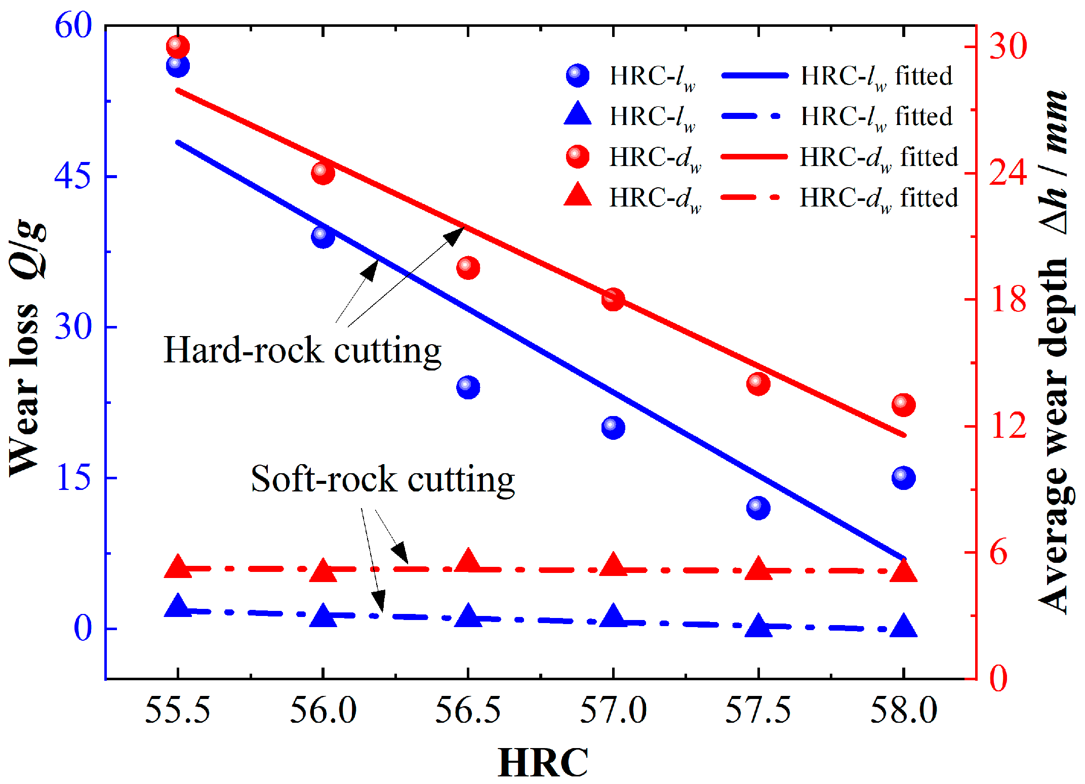
  • The study shows that the type of cutter ring wear is dominated by abrasive wear, with even wear having the highest probability of occurrence, followed by bias wear and ring chipping. There is a negative correlation between the amount of cutter wear and the hardness of the material, and high hardness can prolong the service life. The penetration of the cutter ring in rocks of different strengths reflects different wear levels.
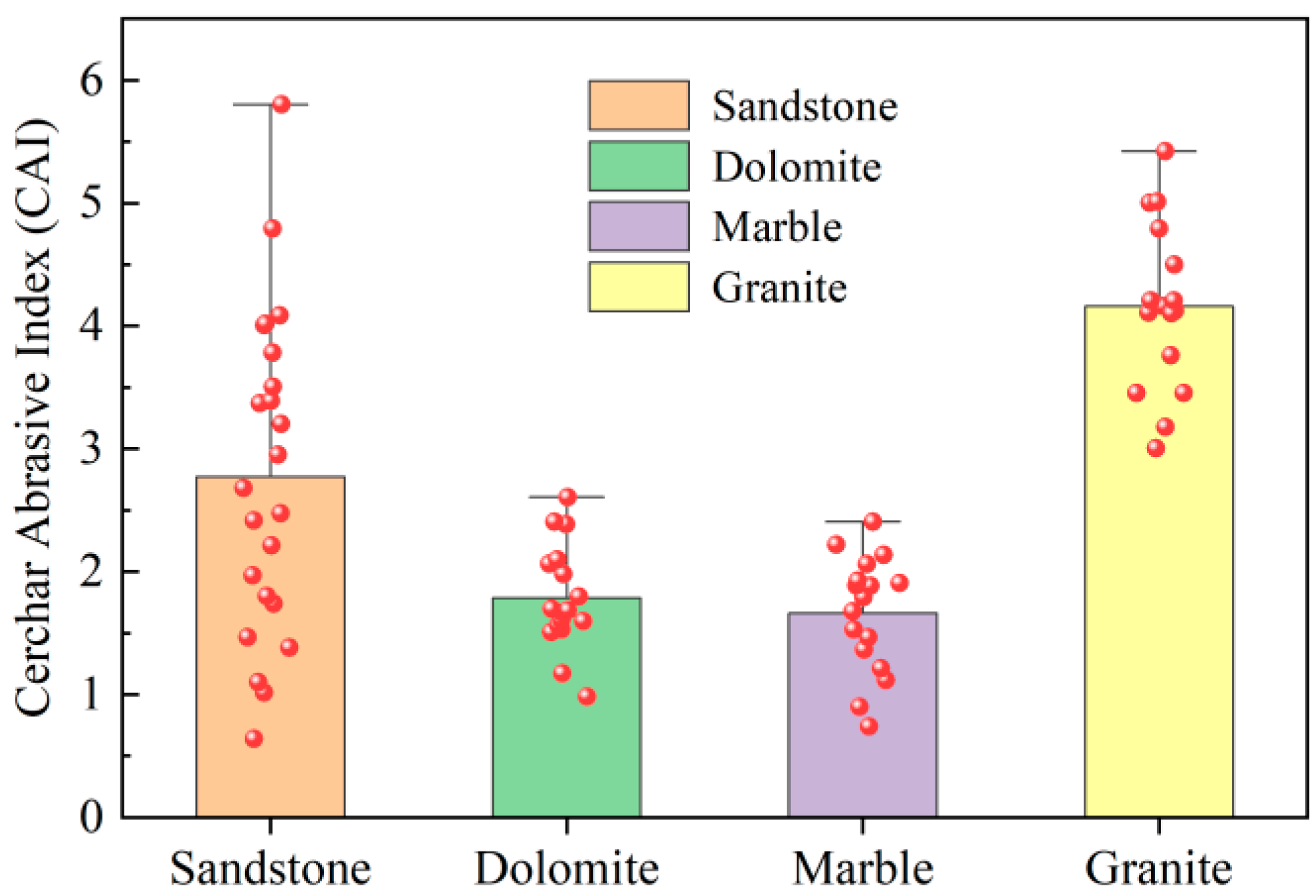
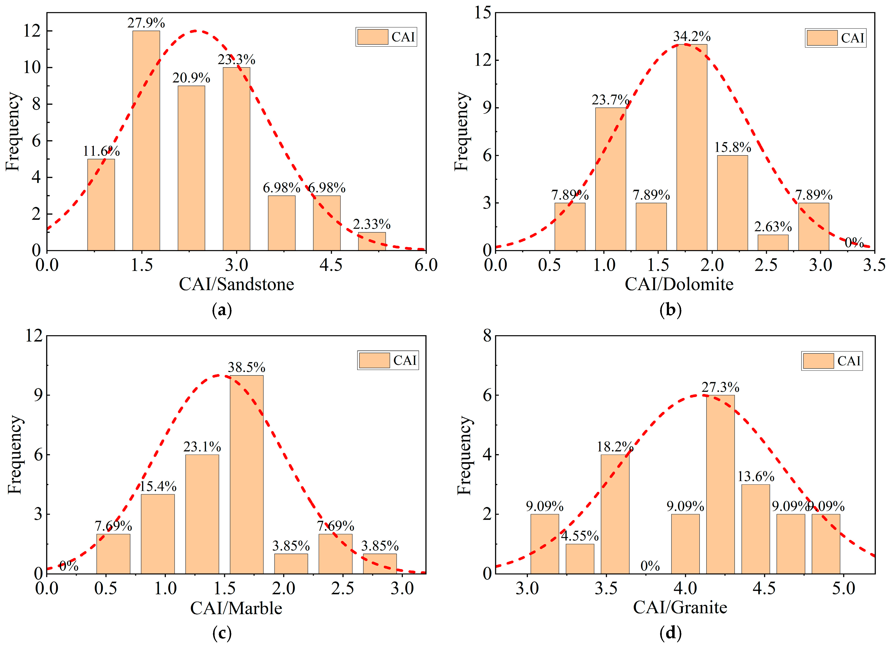
  • High-strength granite has the highest abrasiveness to the steel material of the cutter ring, and the cutter cutting medium-strength rock has less wear, and the full contact friction between the soft rock and the cutter increases the abrasion area and the abrasion amount, which leads to increased wear. An increase in the rock strength makes the rock CAI characteristics and cutter ring wear increase, and this index can reflect the degree of cutter ring wear.
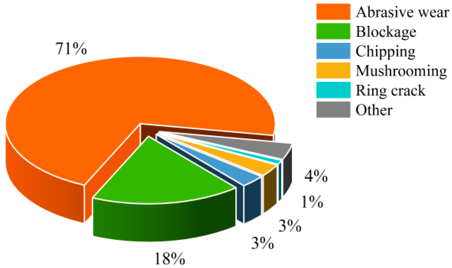
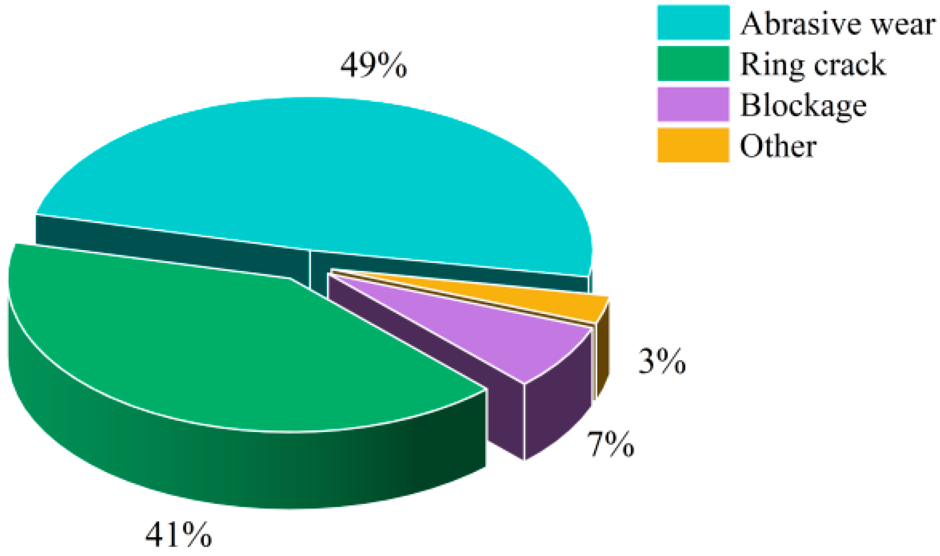
  • In the shield tunnelling process, the wear degree of cutting hard rock is higher, and the proportion of wear types is 71% for abrasive wear and 18% for cutting ring breakage, of which uniform wear occupies 54% of the total wear. When cutting soft and hard composite strata, the proportion of abrasive wear decreases to only about 49%, and the proportion of cutter ring breakage is 41%, indicating that cutting soft rock reduces the condition of abrasive wear.
  • Comparative analyses show that the damage patterns of hard–soft rock cutting are different. In the cutting process of high-strength rock, the cutter ring wear is mainly at the bottom of the radial outer edge, with uniform wear. The area of cutter wear in cutting soft rock is mainly distributed in the area on both sides of the cutter head, which can easily produce the phenomenon of a cutter rim grinding tip.
  • With the same rock strength and considering the temperature effect, the wear depth of cutting hard rock has a power function relationship with the installation radius and is proportional to the shield distance. The predicted value is lower than the actual measured value.
  • The wear prediction model considering the thermal effect is closer to the actual value. Cutting medium-hard rock and hard rock, the maximum radius wear depth reaches 25.8 mm and 34.1 mm, respectively, and the prediction error is 3.7% and 5.1%. The errors remain within reasonable limits.
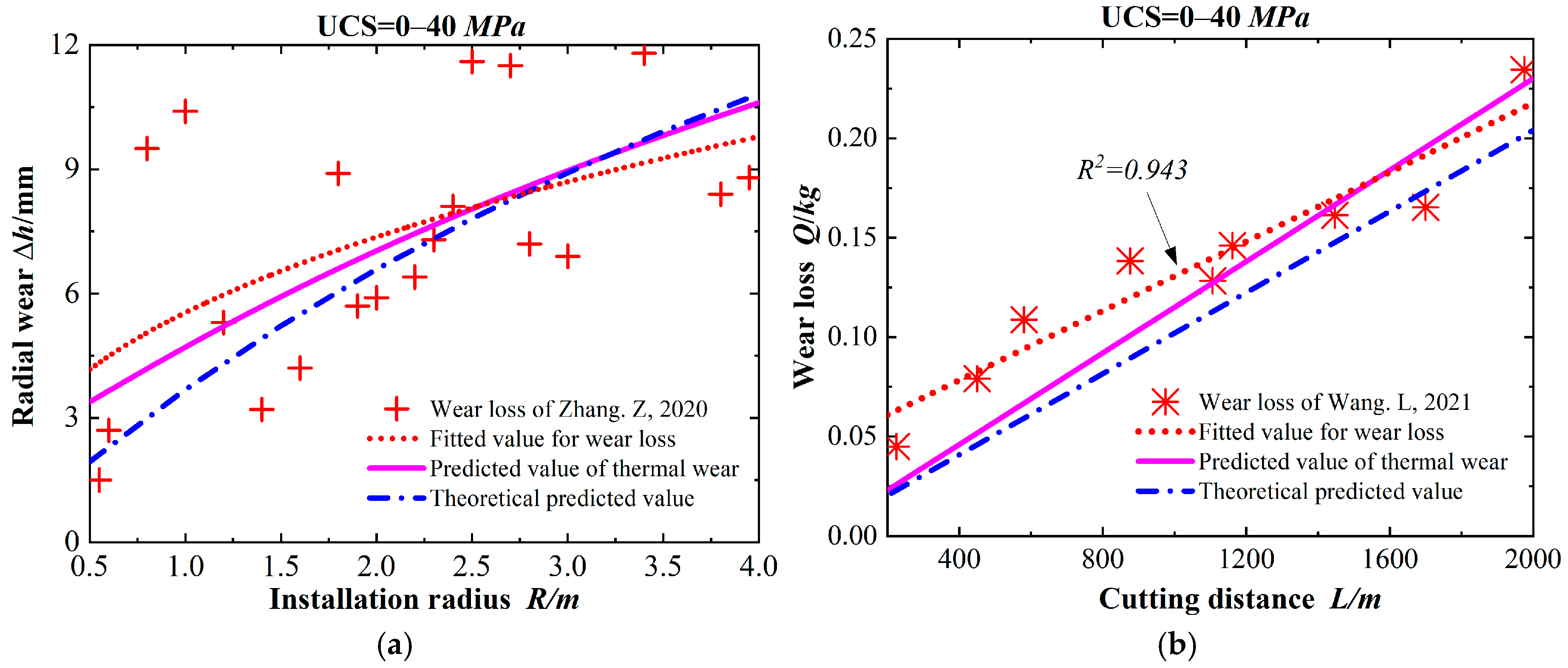
  • The predicted wear for cutting soft rock increases gradually with the radius, and the loss of wear mass shows a positive correlation with the cutting distance, with a minimum prediction error of 8.4%. It is generally lower than the actual value.

Author Contributions

X.L., conceptualisation, methodology, investigation, data curation, writing original draft, writing—review and editing and visualisation. Y.C., conceptualisation, methodology, validation, visualisation, resources and supervision. S.L., conceptualisation and methodology. T.M.F.-S., conceptualisation, methodology, validation, visualisation, resources and supervision. All authors have read and agreed to the published version of the manuscript.

Funding

This research and the APC were funded by the Ministry of Science and Technology of the People’s Republic of China (No. G2021013020L), the Natural Science Foundation of Shanghai Municipality (No. 22WZ2503000), the Natural Science Foundation of Shanghai Municipality (No. 23ZR1443600), and the China Scholarship Council (No. 202110220005).

Institutional Review Board Statement

Not applicable.

Informed Consent Statement

Not applicable.

Data Availability Statement

The data that support the findings of this study are available from the corresponding author upon reasonable request. The data are not publicly available due to privacy.

Acknowledgments

The work presented in this paper was supported by the Ministry of Science and Technology of the People’s Republic of China, the Natural Science Foundation of Shanghai Municipality, and the China Scholarship Council, which are all greatly appreciated. In addition, the authors also thank the three supervisors’ help in different stages of this study. Thanks are also extended to Yiming Zhao of Shanghai Construction Group Co., Ltd. for his help with the case concept and empirical methodology of this study.

Conflicts of Interest

The authors declare that they have no known competing financial interests or personal relationships that could have appeared to influence the work reported in this paper.

References

  1. Jin, D.; Yuan, D.; Li, X.; Su, W. Probabilistic analysis of the disc cutter failure during TBM tunneling in hard rock. Tunn. Undergr. Space Technol. 2021, 109, 103744. [Google Scholar] [CrossRef]
  2. Macias, F.J. Hard Rock Tunnel Boring: Performance Predictions and Cutter Life Assessments. 2016. Available online: https://ntnuopen.ntnu.no/ntnu-xmlui/handle/11250/2429327 (accessed on 7 April 2025).
  3. Macias, F.J.; Dahl, F.; Bruland, A. New rock abrasivity test method for tool life assessments on hard rock tunnel boring: The rolling indentation abrasion test (RIAT). Rock Mech. Rock Eng. 2016, 49, 1679–1693. [Google Scholar] [CrossRef]
  4. Zhang, X.; Lin, L.; Xia, Y.; Tan, Q.; Zhu, Z.; Mao, Q.; Zhou, M. Experimental study on wear of TBM disc cutter rings with different kinds of hardness. Tunn. Undergr. Space Technol. 2018, 82, 346–357. [Google Scholar] [CrossRef]
  5. Plinninger, R.J.; Alber, M.; Düllmann, J. Rock mass-scale factors with an influence on tool wear in the mechanised tunnelling process in hard rock: Gebirgsmaßstäbliche Einflussfaktoren auf den Werkzeugverschleiß bei maschinellen Tunnelvortriebsverfahren im Hartgestein. Geomech. Tunn. 2018, 11, 157–168. [Google Scholar] [CrossRef]
  6. Deliormanlı, A.H. Cerchar abrasivity index (CAI) and its relation to strength and abrasion test methods for marble stones. Constr. Build. Mater. 2012, 30, 16–21. [Google Scholar] [CrossRef]
  7. Elbaz, K.; Shen, S.L.; Cheng, W.C.; Arulrajah, A. Cutter-disc consumption during earth pressure balance tunnelling in mixed strata. Proc. Inst. Civ. Eng.-Geotech. Eng. 2018, 171, 363–376. [Google Scholar] [CrossRef]
  8. Elbaz, K.; Shen, S.L.; Zhou, A.; Yin, Z.Y.; Lyu, H.M. Prediction of disc cutter life during shield tunneling with AI via the incorporation of a genetic algorithm into a GMDH-type neural network. Engineering 2021, 7, 238–251. [Google Scholar] [CrossRef]
  9. Sun, Z.; Zhao, H.; Hong, K.; Chen, K.; Zhou, J.; Li, F.; Zhang, B.; Song, F.; Yang, Y.; He, R. A practical TBM cutter wear prediction model for disc cutter life and rock wear ability. Tunn. Undergr. Space Technol. 2019, 85, 92–99. [Google Scholar] [CrossRef]
  10. Balci, C.; Tumaç, D. Investigation into the effects of different rocks on rock cuttability by a V-type disc cutter. Tunn. Undergr. Space Technol. 2012, 30, 183–193. [Google Scholar] [CrossRef]
  11. Karami, M.; Zare, S.; Rostami, J. Study of common wear prediction models for hard rock TBM disc cutters and comparison with field observation in Kerman water conveyance tunnel. Bull. Eng. Geol. Environ. 2021, 80, 1467–1476. [Google Scholar] [CrossRef]
  12. Frenzel, C.; Käsling, H.; Thuro, K. Factors influencing disc cutter wear. Geomech. Und Tunnelbau Geomech. Und Tunnelbau 2008, 1, 55–60. [Google Scholar] [CrossRef]
  13. Lin, L.; Xia, Y.; Zhang, X. Wear characteristics of TBM disc cutter ring sliding against different types of rock. KSCE J. Civ. Eng. 2020, 24, 3145–3155. [Google Scholar] [CrossRef]
  14. Ren, D.J.; Shen, S.L.; Arulrajah, A.; Cheng, W.C. Prediction model of TBM disc cutter wear during tunnelling in heterogeneous ground. Rock Mech. Rock Eng. 2018, 51, 3599–3611. [Google Scholar] [CrossRef]
  15. Yu, H.; Tao, J.; Huang, S.; Qin, C.; Xiao, D.; Liu, C. A field parameters-based method for real-time wear estimation of disc cutter on TBM cutterhead. Autom. Constr. 2021, 124, 103603. [Google Scholar] [CrossRef]
  16. Ren, D.J.; Shen, S.L.; Zhou, A.; Chai, J.C. Prediction of lateral continuous wear of cutter ring in soft ground with quartz sand. Comput. Geotech. 2018, 103, 86–92. [Google Scholar] [CrossRef]
  17. Wang, L.; Li, H.; Zhao, X.; Zhang, Q. Development of a prediction model for the wear evolution of disc cutters on rock TBM cutterhead. Tunn. Undergr. Space Technol. 2017, 67, 147–157. [Google Scholar] [CrossRef]
  18. Geng, Q.; Wei, Z.; Ren, J. New rock material definition strategy for FEM simulation of the rock cutting process by TBM disc cutters. Tunn. Undergr. Space Technol. 2017, 65, 179–186. [Google Scholar] [CrossRef]
  19. Karami, M.; Zare, S.; Rostami, J. Tracking of disc cutter wear in TBM tunneling: A case study of Kerman water conveyance tunnel. Bull. Eng. Geol. Environ. 2021, 80, 201–219. [Google Scholar] [CrossRef]
  20. Tan, Q.; Zhang, G.J.; Xia, Y.M.; Li, J.F. Differentiation and analysis on rock breaking characteristics of TBM disc cutter at different rock temperatures. J. Cent. South Univ. 2015, 22, 4807–4818. [Google Scholar] [CrossRef]
  21. Munoz, H.; Taheri, A.; Chanda, E. Rock cutting characteristics on soft-to-hard rocks under different cutter inclinations. Int. J. Rock Mech. Min. Sci. 2016, 87, 85–89. [Google Scholar] [CrossRef]
  22. Hutchings, I.; Shipway, P. Tribology: Friction and Wear of Engineering Materials; Butterworth-Heinemann: Oxford, UK, 2017. [Google Scholar]
  23. Sapigni, M.; Berti, M.; Bethaz, E.; Busillo, A.; Cardone, G. TBM performance estimation using rock mass classifications. Int. J. Rock Mech. Min. Sci. 2002, 39, 771–788. [Google Scholar] [CrossRef]
  24. Lan, H.; Xia, Y.; Ji, Z.; Fu, J.; Miao, B. Online monitoring device of disc cutter wear–Design and field test. Tunn. Undergr. Space Technol. 2019, 89, 284–294. [Google Scholar] [CrossRef]
  25. Gong, Q.; Zhao, J. Development of a rock mass characteristics model for TBM penetration rate prediction. Int. J. Rock Mech. Min. Sci. 2009, 46, 8–18. [Google Scholar] [CrossRef]
  26. Acaroglu, O. Prediction of thrust and torque requirements of TBMs with fuzzy logic models. Tunn. Undergr. Space Technol. 2011, 26, 267–275. [Google Scholar] [CrossRef]
  27. Ching, J.; Phoon, K.K. Value of geotechnical site investigation in reliability-based design. Adv. Struct. Eng. 2012, 15, 1935–1945. [Google Scholar] [CrossRef]
  28. Al-Ameen, S.I.; Waller, M.D. The influence of rock strength and abrasive mineral content on the Cerchar Abrasive Index. Eng. Geol. 1994, 36, 293–301. [Google Scholar] [CrossRef]
  29. Pan, Y.C.; Liu, Q.S.; Liu, J.P.; Kong, X.X.; Peng, X.X.; Liu, Q. Investigation on disc cutter behaviors in cutting rocks of different strengths and reverse estimation of rock strengths from experimental cutting forces. Eur. J. Environ. Civ. Eng. 2021, 25, 1–27. [Google Scholar] [CrossRef]
  30. Pan, Y.; Liu, Q.; Peng, X.; Liu, Q.; Liu, J.; Huang, X.; Cui, X.; Cai, T. Full-scale linear cutting tests to propose some empirical formulas for TBM disc cutter performance prediction. Rock Mech. Rock Eng. 2019, 52, 4763–4783. [Google Scholar] [CrossRef]
  31. Xia, Y.; Guo, B.; Tan, Q.; Zhang, X.; Lan, H.; Ji, Z. Comparisons between experimental and semi-theoretical cutting forces of CCS disc cutters. Rock Mech. Rock Eng. 2018, 51, 1583–1597. [Google Scholar] [CrossRef]
  32. Lan, H.; Xia, Y.; Miao, B.; Fu, J.; Ji, Z. Prediction model of wear rate of inner disc cutter of engineering in Yinsong, Jilin. Tunn. Undergr. Space Technol. 2020, 99, 103338. [Google Scholar] [CrossRef]
  33. Sun, Z.; Yang, Y.; Chen, K.; Li, F.; Zhou, J.; Zhang, B.; Chen, Q. Disc cutter’s rock breaking ability and wear resistance in extremely hard rock: A case study in Qinling tunnel of Han River to Wei River Water Diversion Project. Geotech. Geol. Eng. 2019, 37, 4901–4910. [Google Scholar] [CrossRef]
  34. Yagiz, S. Utilizing rock mass properties for predicting TBM performance in hard rock condition. Tunn. Undergr. Space Technol. 2008, 23, 326–339. [Google Scholar] [CrossRef]
  35. Li, Y.; Di, H.; Yao, Q.; Fu, L.; Zhou, S. Prediction model for disc cutter wear of tunnel boring machines in sandy cobble strata. KSCE J. Civ. Eng. 2020, 24, 1010–1019. [Google Scholar] [CrossRef]
  36. Tang, S.; Zhang, X.; Liu, Q.; Zhang, Q.; Li, X.; Wang, H. Experimental study on the influences of cutter geometry and material on scraper wear during shield TBM tunnelling in abrasive sandy ground. J. Rock Mech. Geotech. Eng. 2024, 16, 410–425. [Google Scholar] [CrossRef]
  37. Gharsallaoui, H.; Jafari, M.; Holeyman, A. Cavity expansion in rock masses obeying the “hoek–brown” failure criterion. Rock Mech. Rock Eng. 2020, 53, 927–941. [Google Scholar] [CrossRef]
  38. Wang, Z.F.; Shen, S.L.; Ho, C.E.; Kim, Y.H. Investigation of field-installation effects of horizontal twin-jet grouting in Shanghai soft soil deposits. Can. Geotech. J. 2013, 50, 288–297. [Google Scholar] [CrossRef]
  39. Kalayci Sahinoglu, U.; Ozer, U. The prediction of cutter wear from temperature measurements on TBM discs and cutting face. Arab. J. Geosci. 2020, 13, 207. [Google Scholar] [CrossRef]
  40. Tian, J.; Hu, Y.; Liu, X.; Yang, Z. Wear performance and mechanisms of H13 steels sliding against different Rock types. Surf. Topogr. Metrol. Prop. 2020, 8, 025003. [Google Scholar] [CrossRef]
  41. Zhang, Z.; Zhang, K.; Dong, W.; Zhang, B. Study of rock-cutting process by disc cutters in mixed ground based on three-dimensional particle flow model. Rock Mech. Rock Eng. 2020, 53, 3485–3506. [Google Scholar] [CrossRef]
  42. Wang, L.; Kang, Y.; Zhao, X.; Zhang, Q. Disc cutter wear prediction for a hard rock TBM cutterhead based on energy analysis. Tunn. Undergr. Space Technol. 2015, 50, 324–333. [Google Scholar] [CrossRef]
Figure 1. Horizontal distribution of the composite strata and a cross-section of the shield tunnel path.
Applsci 15 04183 g001
Figure 2. Proportion of wear types for cutter cutting hard rock.
Applsci 15 04183 g002
Figure 3. Proportion of wear types for cutter cutting soft and hard composite strata.
Applsci 15 04183 g003
Figure 4. Relationship between the wear distance and wear volume over the life of the cutter.
Applsci 15 04183 g004
Figure 5. The relationship between the hardness of the cutter ring and the wear loss.
Applsci 15 04183 g005
Figure 6. Relationship between penetration and external thrust and ultimate torque for rocks of different strengths.
Applsci 15 04183 g006
Figure 7. CAI values of 4 typical rock types.
Applsci 15 04183 g007
Figure 8. Frequency distribution and fitting curve of CAI for typical rocks. (a) Index of sandstone, (b) Index of dolomite, (c) Index of marble, and (d) Index of granite.
Applsci 15 04183 g008
Figure 9. Relationship between particle abrasivity index and rock strength. Test data points and fitted values according to Deliormanlı [6] and Al-Ameen [28].
Applsci 15 04183 g009
Figure 10. Relationship between abrasive index and abrasion degree for rocks of different strengths.
Applsci 15 04183 g010
Figure 11. Cutting and breaking force distribution model.
Applsci 15 04183 g011
Figure 12. Movement trajectory of shield cutter and cutter–rock cutting mode. (a) Cutter cutting motion trajectory, the arrow is the advancing direction. (b) Schematic of cutter cutting rock, red circle is cutting groove.
Applsci 15 04183 g012
Figure 13. Mechanism of plasticity removal via abrasive wear.
Applsci 15 04183 g013
Figure 14. Analysis of abrasive wear calculation model.
Applsci 15 04183 g014
Figure 15. Cutter wear and rock damage for cutting hard rock.
Applsci 15 04183 g015
Figure 16. Wear analysis model for cutter rings. (a) Wear model of the outer edge of the cutter; (b) volumetric wear analysis of the cutter ring surface. The cutter ring analysis model is shown in blue and the amount of changing wear is shown in red.
Applsci 15 04183 g016
Figure 17. Cutter wear and rock damage for cutting soft rock.
Applsci 15 04183 g017
Figure 18. Computational model of circular hole expansion theory.
Applsci 15 04183 g018
Figure 19. Analysis of unit stress state in plastic region.
Applsci 15 04183 g019
Figure 20. Distribution of wear depth with installation radius. (a) Radial wear fitted and comparative study of Frenzel 2008 [12] and Jin. D 2021 [1], UCS = 40–80 MPa. (b) Radial wear fitted and comparative study of Yu. H 2021 [15], UCS = 80–120 MPa. (c) Radial wear fitted and comparative study of Macias 2016 [2], UCS ≧ 120 MPa.
Applsci 15 04183 g020
Figure 21. Distribution of wear depth with shield distance. Fitted value and comparative study of Yu.H 2021 [15]. (a) Radial wear at R = 1650 mm. (b) Radial wear at R = 2475 mm. (c) Radial wear at R = 3300 mm.
Applsci 15 04183 g021
Figure 22. Distribution of wear level for cutting soft rock. (a) Distribution of wear depth with installation radius, Zhang. Z 2020 [41]; (b) distribution of wear mass with cutting distance, Wang. L 2021 [42].
Applsci 15 04183 g022
Table 1. TBM boring parameters and hard-rock geological characteristics of shield engineering [8,26].
ParametersProject Cases
NTNU CaseSJTU CaseTUM and BJU Cases
Project locationNorth-central EuropeSouth AsiaCentral Europe and East Asia
Approximate tunnel length (km)7.04.32.4
Rock samplesGraniteBasalt and brecciaMarble and granite
Rock strength rangeHigh–extremely highMedium–very highMedium
UCS (MPa)≥12080–12040–80
Rock density (g/m3)2.6~2.72.8~3.02.6~3.3
Tunnel diameter (m)7.26.66.5
Disc cutter diameter (mm)483483483
Cutter head rotation speed (rpm)0–8.70–7.05.5–8.0
Cutter thrust (kN)14001070214
Table 2. Calculated parameters for disc cutter ring materials.
Disc Cutter Ring Material PropertiesValue
Density (kg/m3)7850
Young’s modulus (GPa)210
Poisson’s ratio0.3
Hardness HRC57
Uniaxial compressive (MPa)2560
Angle of the disc cutter ring (°)26
Ultimate load (MPa)250
Table 3. TBM boring parameters and soft-rock geological characteristics of shield engineering [17,41,42].
ParametersProject Cases
Shenzhen CaseGansu Case
Project locationEast AsiaEast Asia
Approximate tunnel length (km)2.718.2
Rock samplesHighly/moderately weathered graniteMudstone and gneiss
Rock strength rangeLow–mediumLow–medium
UCS (MPa)5–18/15.7–56.85–68
Rock density (g/m3)2.32.6
Tunnel diameter (m)8.55.75
Disc cutter diameter (mm)432432
Cutter head rotation speed (rpm)1.8–2.00–8.1
Cutter thrust (kN)500–60021,420
Disclaimer/Publisher’s Note: The statements, opinions and data contained in all publications are solely those of the individual author(s) and contributor(s) and not of MDPI and/or the editor(s). MDPI and/or the editor(s) disclaim responsibility for any injury to people or property resulting from any ideas, methods, instructions or products referred to in the content.

