Article

Investigating Load-Bearing Capabilities and Failure Mechanisms of Inflatable Air Ribs

1
School of Mechanical-Electronic and Vehicle Engineering, Beijing University of Civil Engineering and Architecture, Beijing 102627, China
2
School of Mechanical and Electrical Engineering, Beijing Institute of Graphic Communication, Beijing 102600, China
*
Author to whom correspondence should be addressed.
Appl. Sci. 2025, 15(8), 4154; https://doi.org/10.3390/app15084154
Submission received: 23 January 2025 / Revised: 2 April 2025 / Accepted: 6 April 2025 / Published: 10 April 2025

Abstract

:
Air ribs are the critical components of tents. Ten air ribs were designed to study the influence of rise–span ratios on load-bearing performance and explore the failure mechanism. According to the maximum stress that appears at the top and bending regions of the rib, the ribs can be divided into an upright region and an arc-like region. So, a segmentation failure competition mechanism was proposed. In order to enhance the bearing performance, the upright region and arc-like region should be designed to fail at the same time. For the rib named 0.333-S, the stress distributes uniformly and the critical load is 2.62 kN / m 2 ; the upright region and arc-like region fail at the same time. For the rib named 0.5-S/R, the critical load is 1.465 kN / m 2 , and it fails at the upright region, resulting in a reduction of 44%. The tent with ribs named 0.333-S shows better resistance performance against wind load, and the end ribs of this tent deform less. Its maximum displacement is 0.112 m, which is reduced by 65.8% compared with that of the original upright arch tent.

1. Introduction

Inflatable membrane structures are celebrated for remarkable lightness, flexibility, and strong adaptability [1]. They are widely used in various fields, including tourism, aerospace, military operations [2,3], and disaster relief [4]. As such, the optimal design is crucial for ensuring safety and durability [5,6]. Despite these advantages, the overall stiffness of membrane structures is too low to resist deformation under wind loads [7]. The Guangzhou Olympic Sports Center Badminton Hall collapsed in convective weather, highlighting that enhancing the load-bearing performance of tents is important. The structures of tents should be redesigned to enhance wind resistance capabilities.
Due to the high sensitivity to wind, the wind-induced responses of membrane structures have been analyzed extensively. Liu et al. [8] studied the stochastic vibrations and structural reliability of hyperbolic paraboloid composite membrane structures under wind loads. The structural performance functions of the composites were proposed. Sun et al. [9] analyzed the wind pressure coefficients of an oval arch membrane structure. The influence of the rise–span ratio, wind direction, and terrain were studied, and suitable zoning was proposed for oval membrane structures. Additionally, Kandel [10] and Chen [11] et al. assessed the wind-induced responses of oval arch-supported membrane structures by wind tunnel data and random vibration time-history analysis. The gust load factors and nonlinear adjustment factors were introduced to an equivalent static design method. Then, wind speed, direction, and structural geometry were used to evaluate the maximum stress of structures. Liu et al. [12] theoretically investigated the galloping phenomenon of tensioned orthotropic saddle-shaped closed membranes. The study demonstrated that the rise–span ratio is the primary control parameter for the critical wind speed. An accurate theoretical solution was provided for the aerodynamic stability of saddle membrane structures.
To mitigate damage induced by wind loads, it is crucial to enhance the load-bearing capabilities of membrane structures. Chen et al. [13] developed an equivalent static analysis method to improve the load-bearing efficiency. It is conducted by exploring wind responses and anti-wind designs of spherical inflatable membrane structures. Similarly, Shi [14] and Xue [15] et al. introduced a novel method to design the free-form optimized structure of cable membrane structures within certain constraints. The stiffness of new structures was enhanced compared to membrane structures without cables. Marbaniang et al. [16] developed a new interactive generative framework that combines evolutionary algorithms with shape parameterization and the structure of tensile membrane structures (TMSs) together. This framework is adaptable to various shapes and can be used for optimizing prestress. Nguyen et al. [17] improved the load-carrying capacity of membrane structures by exploiting the functionally graded carbon-nanotube-reinforced composite (FG-CNTRC) material. These studies are pivotal in enhancing the load-bearing performance of membrane structures.
The air-ribbed tent, as a new type of membrane structure, is supported by air ribs. The external loads are applied to the tarpaulin of the tent directly, and the loads are transmitted to the air ribs through adhesive strips. Therefore, the load-bearing capacity of the air ribs influences the load-bearing capacity of the whole tent. Zheng et al. [18] proposed an air-ribbed membrane structure that retains the advantages of rapid deployment and flexible space. The tent was able to withstand the wind load and snow load that occurs once in 50 years. Fan et al. [19] analyzed the local structure of a disaster relief tent using ANSYS 14.5, and the suitable range of the rise–span ratio was determined by the displacement and stress results of the air ribs. Wang et al. [20] analyzed the impact of wrinkles on the vibration characteristics of inflatable arches, noting that the initial wrinkling position is closely related to the inflation pressure. Liu et al. [21] studied the influence of the pressure, the number of ribs, and the wind ropes on the load-bearing performance of tents and obtained an optimized structure using the response surface methodology. Guo et al. [22] conducted an experimental analysis of the performance of inflatable frames, examining their structural response under both horizontal and vertical loads. The study proves that the presence of creasing can lead to catastrophic structural failure.
Additionally, the load-bearing mechanisms of air ribs have been studied. Malm et al. [23] tested the bending performance of air ribs under different inflation pressures. It was concluded that the air-ribbed tents could be analyzed by the traditional beam theory before local buckling occurred. Xue et al. [24] proposed that the buckling behavior of inflatable arches can be simplified to a pseudo-bending beam model. The load distribution, material properties, inflation pressure, and rise–span ratio all significantly affect the buckling characteristics of inflatable arches. Clapp [25] and Roekens [26] et al. studied the bending behavior of inflatable arches by controlling the load and boundary conditions of the structure. Zhao et al. [27] studied the deformation characteristics of inflatable arches and obtained the location of wrinkles by experiments and numerical calculation. It was found that the diameter, depth, and span of the inflatable arch have a significant impact on the load-bearing capacity of the structure.
This paper aims to analyze the influence of structures on the load-bearing performance of air ribs. Ten air ribs of different rise–span ratios were designed to calculate the ultimate bearing capacity. The segmentation failure competition mechanism is proposed to explain the buckling behavior of ribs under vertical load. Based on the performance of single ribs, tents with different ribs were built. The stress and deformation of tents under wind loads were studied by the CFD-FEM method. The method can be used to improve the wind resistance of tents, and the best structure is proposed.

2. The Load-Bearing Performance of Air Ribs with Different Rise–Span Ratios

The air rib typically has a tubular shape, with the membrane forming a closed curved surface. When inflated, it creates a self-balancing system that supports the inflatable tent. Therefore, the rigidity of a rib is crucial to evaluate the load-bearing capacity of the tent. The structure of a rib can be described by the rise–span ratio, which influences the stability of the ribs. The rise–span ratio is suggested to be between 0.333 and 0.667 by the Technical Specification for Membrane Structures [28]. The structure of a usual rib is a semicircle whose rise–span ratio is 0.5. Then, the influence of the rise–span ratio on the load-bearing performance of air ribs is analyzed.

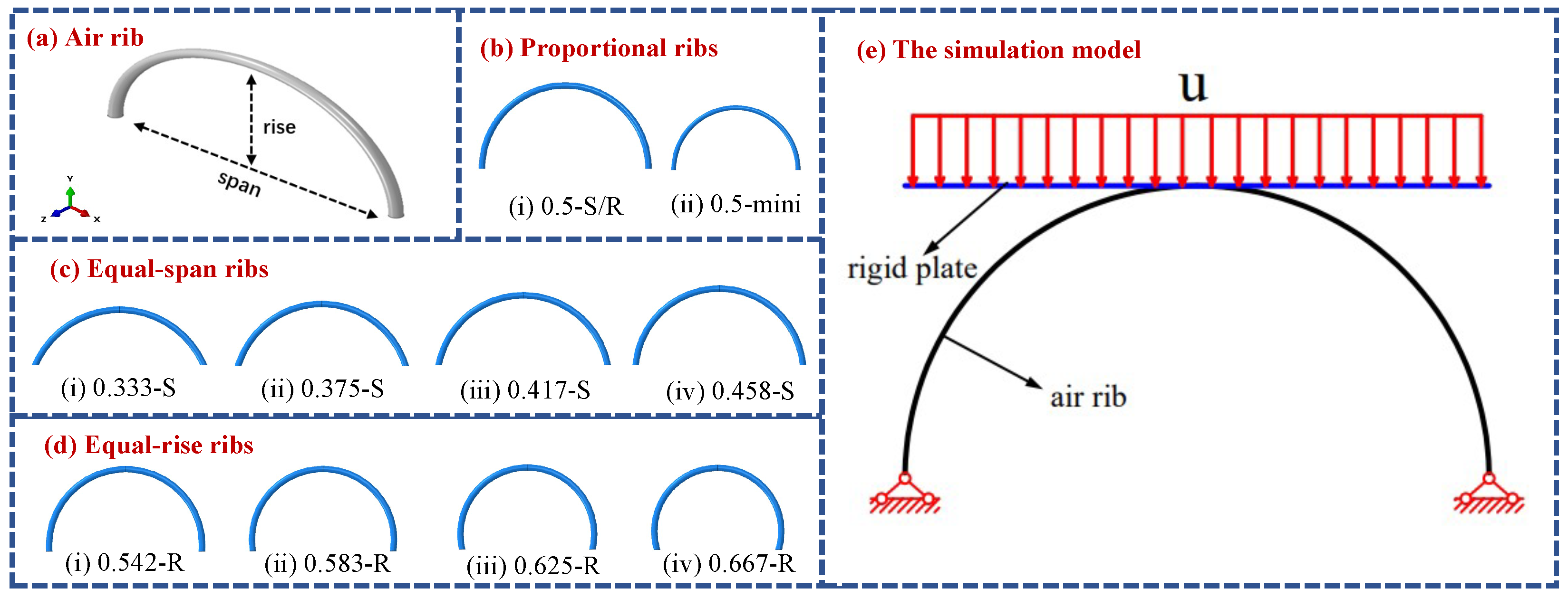
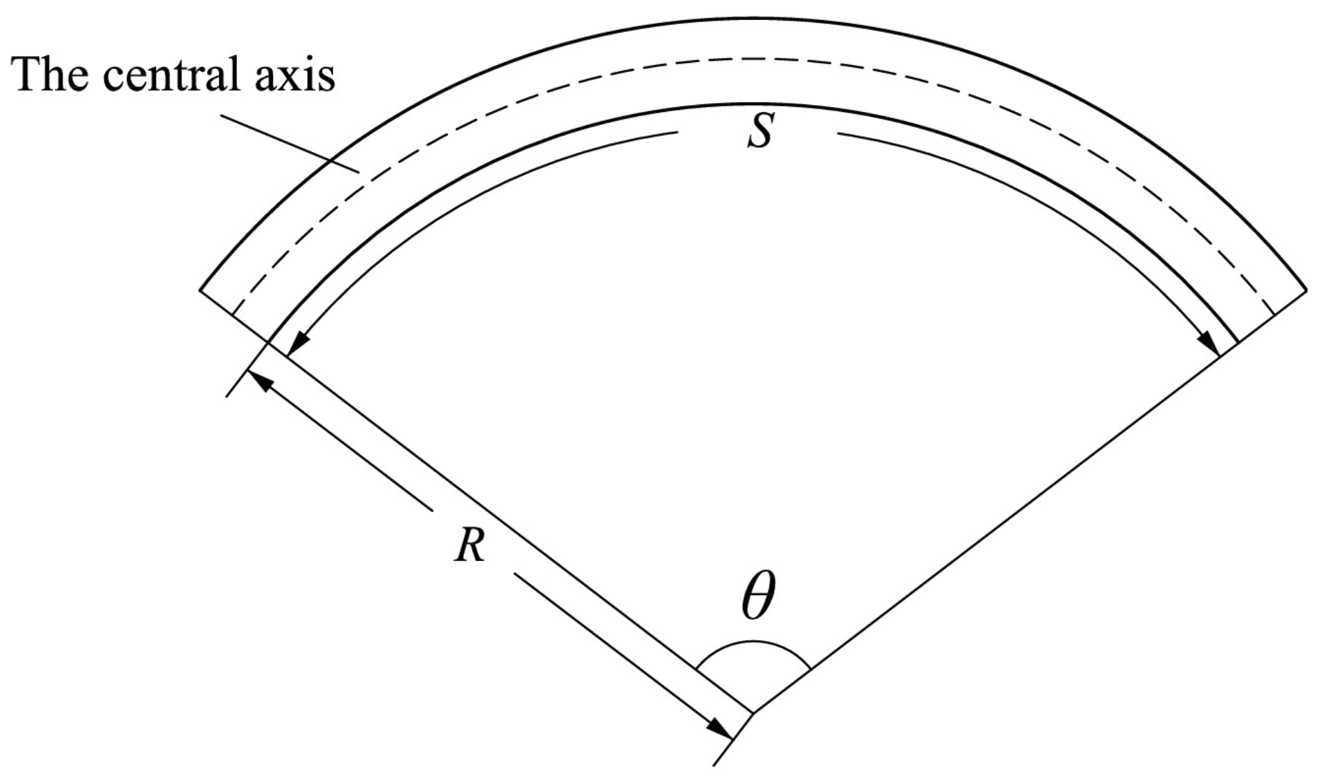
2.1. The Simulation Model of Air Ribs Under Load

Ten air ribs with different rise–span ratios were designed. The air ribs are made of high-strength textile material, which was purchased from Zhongyuan Textile Co. (Suning, Cangzhou, China). The parameters and material properties of the air ribs are shown in Table 1. The span of a usual air rib is 8 m, and the rise is 4 m. The internal pressure of air ribs is 0.2 MPa to ensure stability. The cross-sectional diameter of each rib is 0.3 m. The air ribs are divided into three groups:
(1)
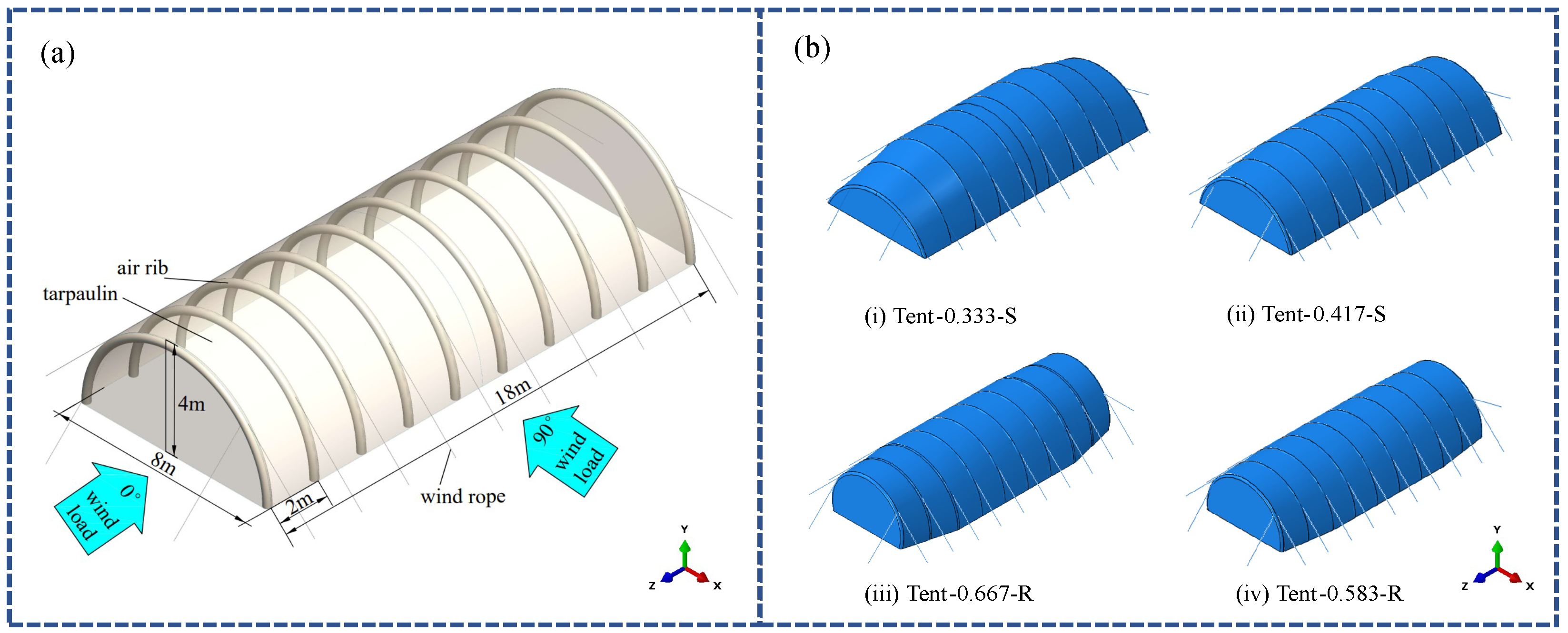
Proportional ribs: These ribs maintain a consistent rise–span ratio, with both rise and span scaling proportionally. The rise–span ratio of the air ribs is 0.5, as shown in Figure 1b, and they are named 0.5-S/R and 0.5-mini.
(2)
Equal-span ribs: These ribs have a fixed span of 8 m, while the rise varies proportionally. The air ribs are classified based on their rise–span ratios, such as 0.333-S, 0.375-S, 0.417-S, and 0.458-S, as shown in Figure 1c.
(3)
Equal-rise ribs: These ribs have a fixed rise of 4 m, while the span varies proportionally. The air ribs are named according to their rise–span ratios, such as 0.532-R, 0.583-R, 0.625-R, and 0.666-R, as shown in Figure 1d.
The simulation model for calculating the bearing performance of the air ribs is illustrated in Figure 1e. The model consists primarily of air ribs and a rigid plate. The model is based on an implicit solution in ABAQUS 2021 while simplifying the membrane material properties and ignoring the effect of membrane anisotropy on structural statics. The rigid plate is constrained to move downward only at a speed of 0.05 m/s for 10 s. It is ensured that the load is applied in the negative y-axis direction, while the displacement of the rigid plate corresponds to the deformation at the top of the air rib. The hinge constraints are applied to the bottom of the air ribs to simulate realistic movements. The support force of the air rib can be monitored by a reference point on the rigid plate. There is no energy transfer between the rigid plate and the air rib.

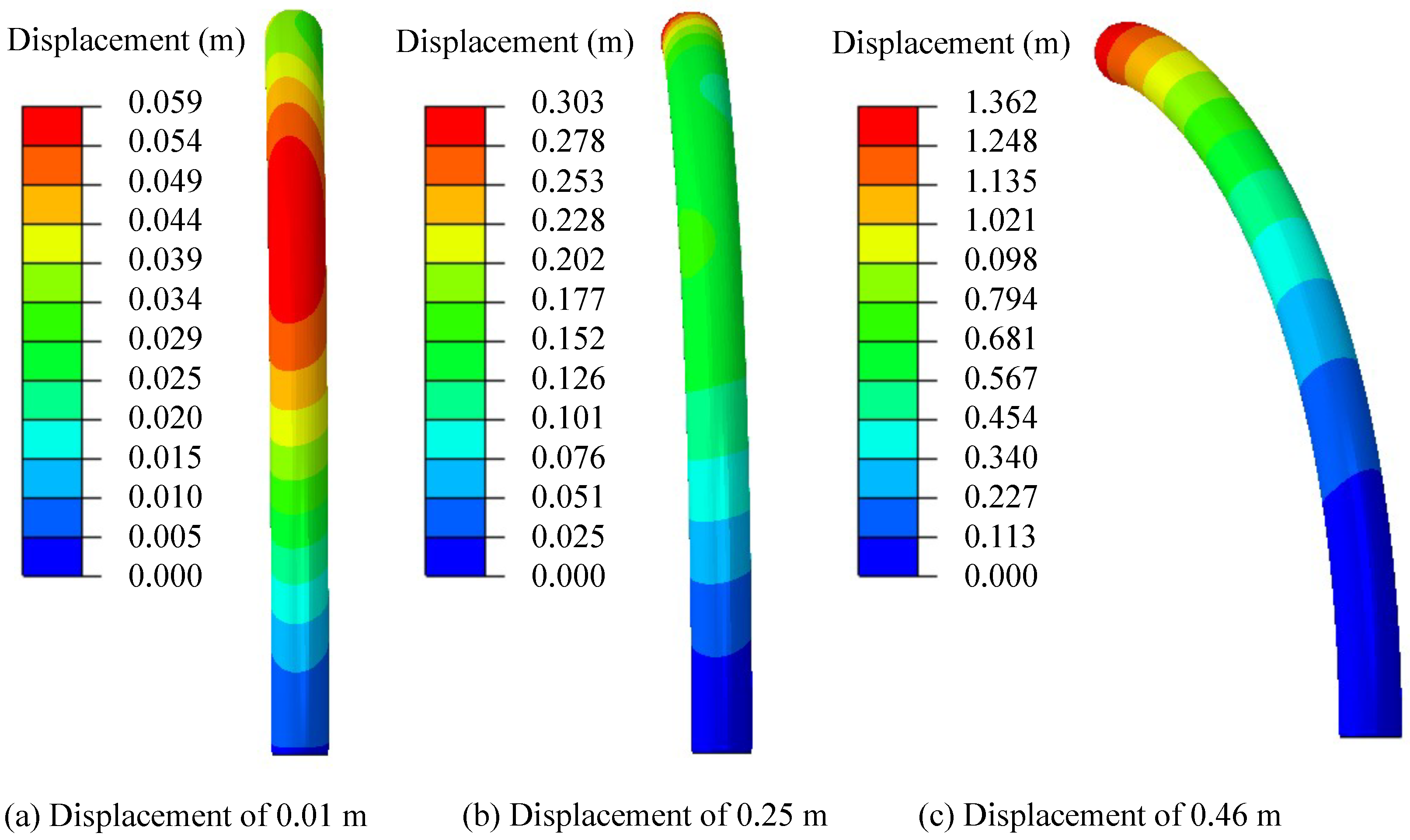
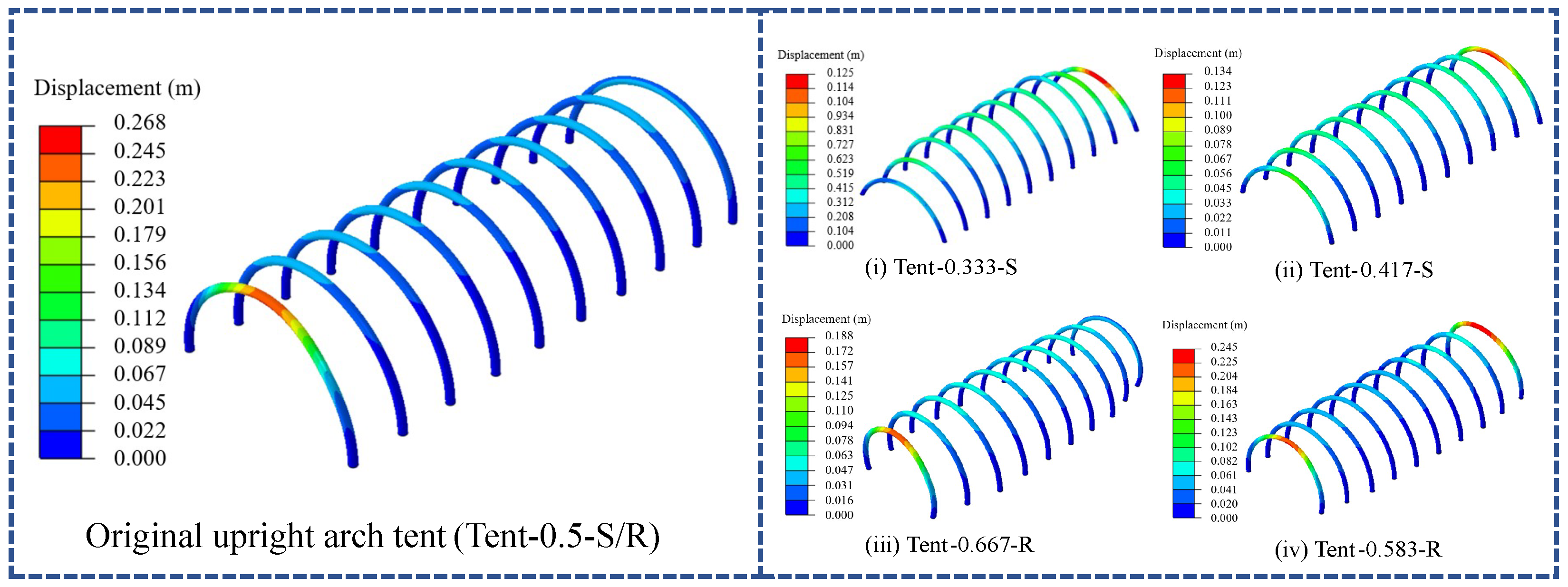
2.2. The Deformation Performance of Air Ribs

The deformation of the air rib named 0.5-S/R is shown in Figure 2. As the plate moves downward, the air rib exhibits a different shape. When the plate moves down 0.01 m (Figure 2a), the rib begins to expand outward at the top and waist regions. With downward movement of the plate to 0.25 m (Figure 2b), the air rib starts to incline sidewise, the main deformation appears at the top, and the maximum deformation is 0.303 m. When the plate goes down further to 0.46 m (Figure 2c), the air rib collapses largely, and it is unable to provide effective support.

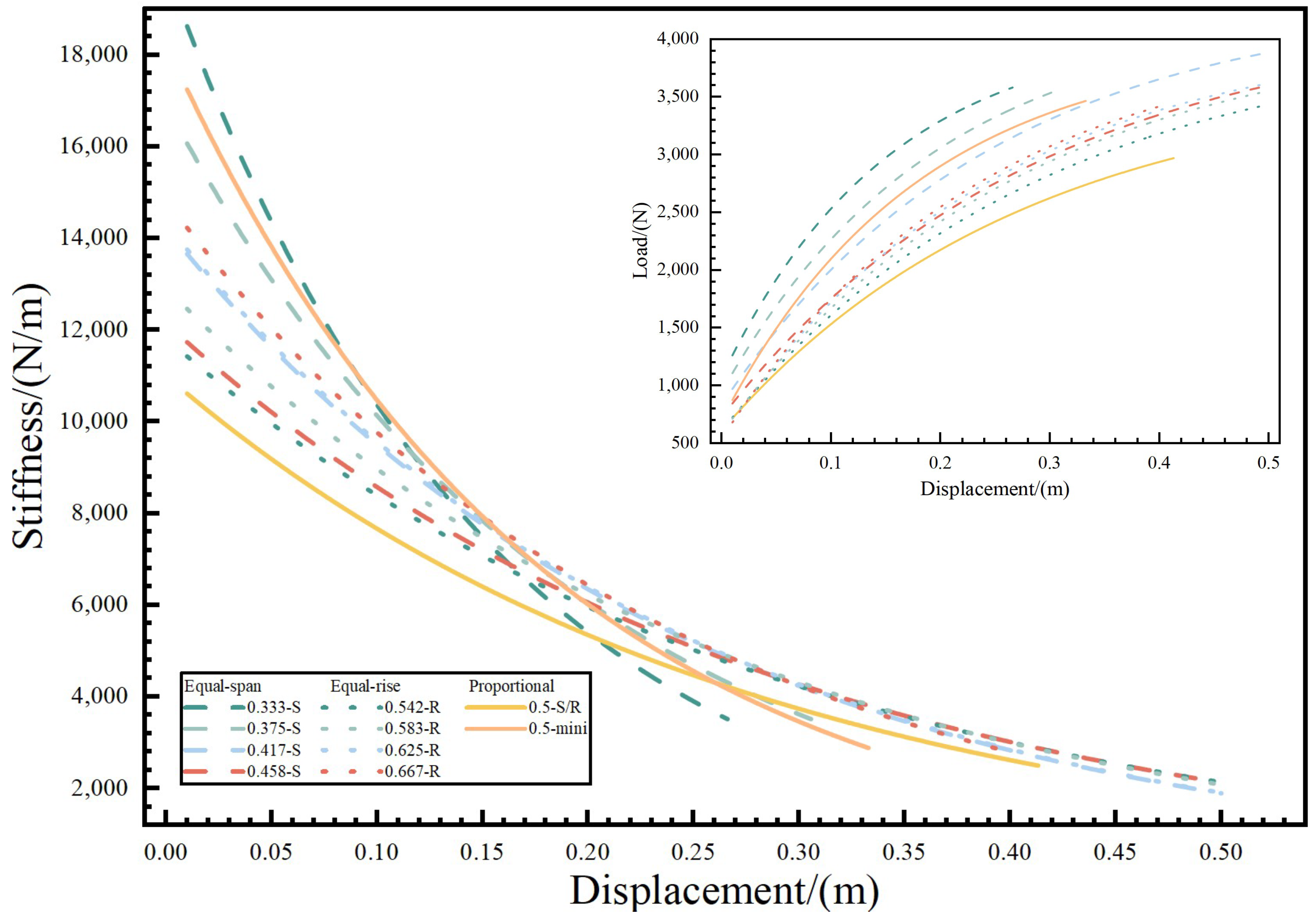
2.3. The Analysis of the Stiffness with Different Rise–Span Ratios

Stiffness is a measure of a structure’s resistance to deformation. Therefore, the stiffness of the air rib can be determined by calculating the slope of the displacement–force curve of the rigid plate. Figure 3 illustrates the trend of the displacement with the resisted load and stiffness. All the curves exhibit the same trend that the resisted force increases with the downward movement of the rigid plate. For the equal-spans group, the bearing capacity is weakened with the increase in the rise under the same deformation conditions. For the equal-rises group, the bearing capacity is enhanced with the increasing of the span under the same deformation conditions. At the same displacement, the air rib named 0.5-S/R provides the least support, while the rib named 0.333-S provides the best support. Additionally, proportionally scaling the air ribs named 0.5-mini can improve their support performance. The maximum supporting load of the air rib named 0.5-S/R is 2968.85 N, while the air rib named 0.417-S can support a maximum load of 3915.85 N. To describe the ability to resist deformation, the stiffness of the air ribs is calculated. The stiffness of the air rib decreases nonlinearly with the increase in the displacement. In the early stage, the stiffness of air ribs is larger than 10,000 N/m, reflecting a robust resistance to deformation. The rib named 0.333-S has the largest curvature, and the load-bearing performance is the best. The stiffness of model 0.333-S is the largest and decreases quickly. It means that the rib named 0.333-S can resist more load at first and is hard to deform. When the rise–span ratio is 0.5, the air rib is the longest, and the stiffness is the lowest.

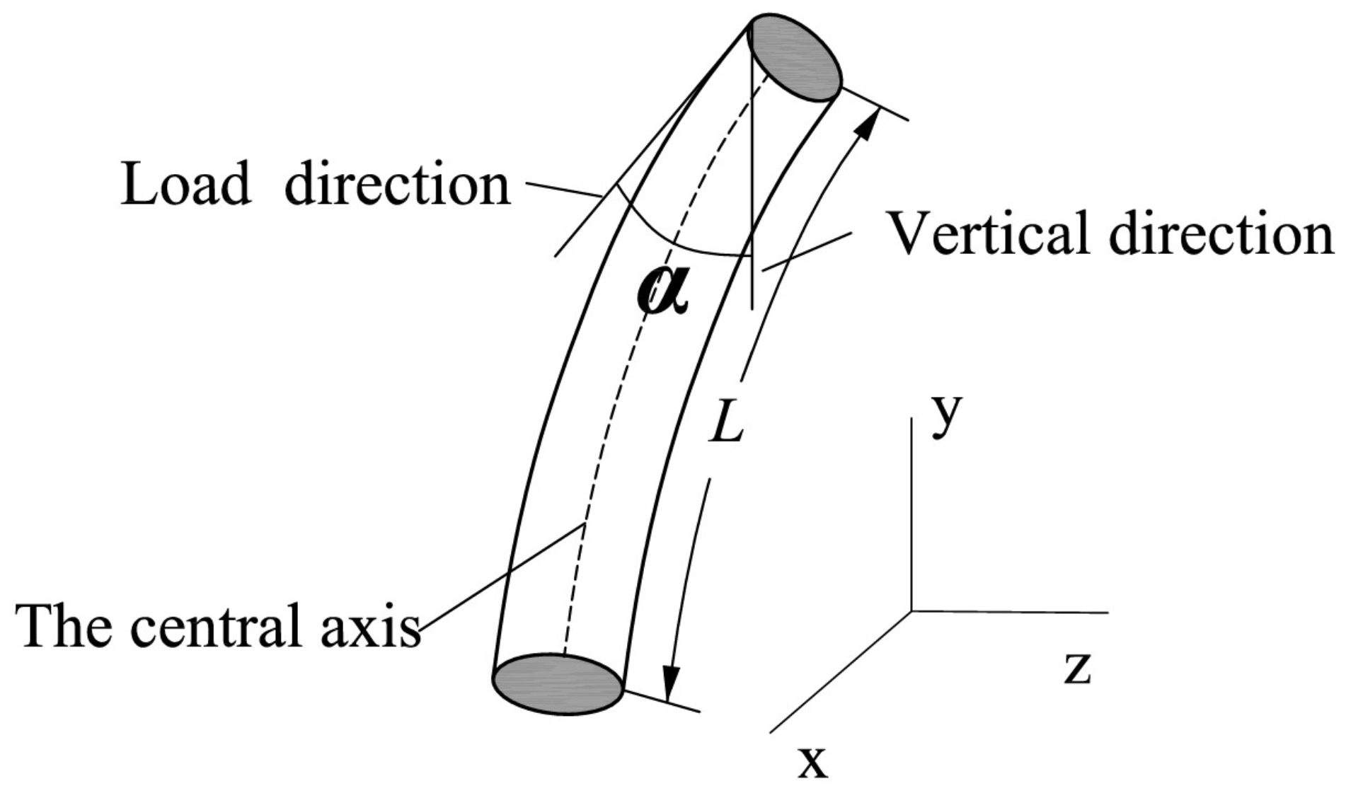
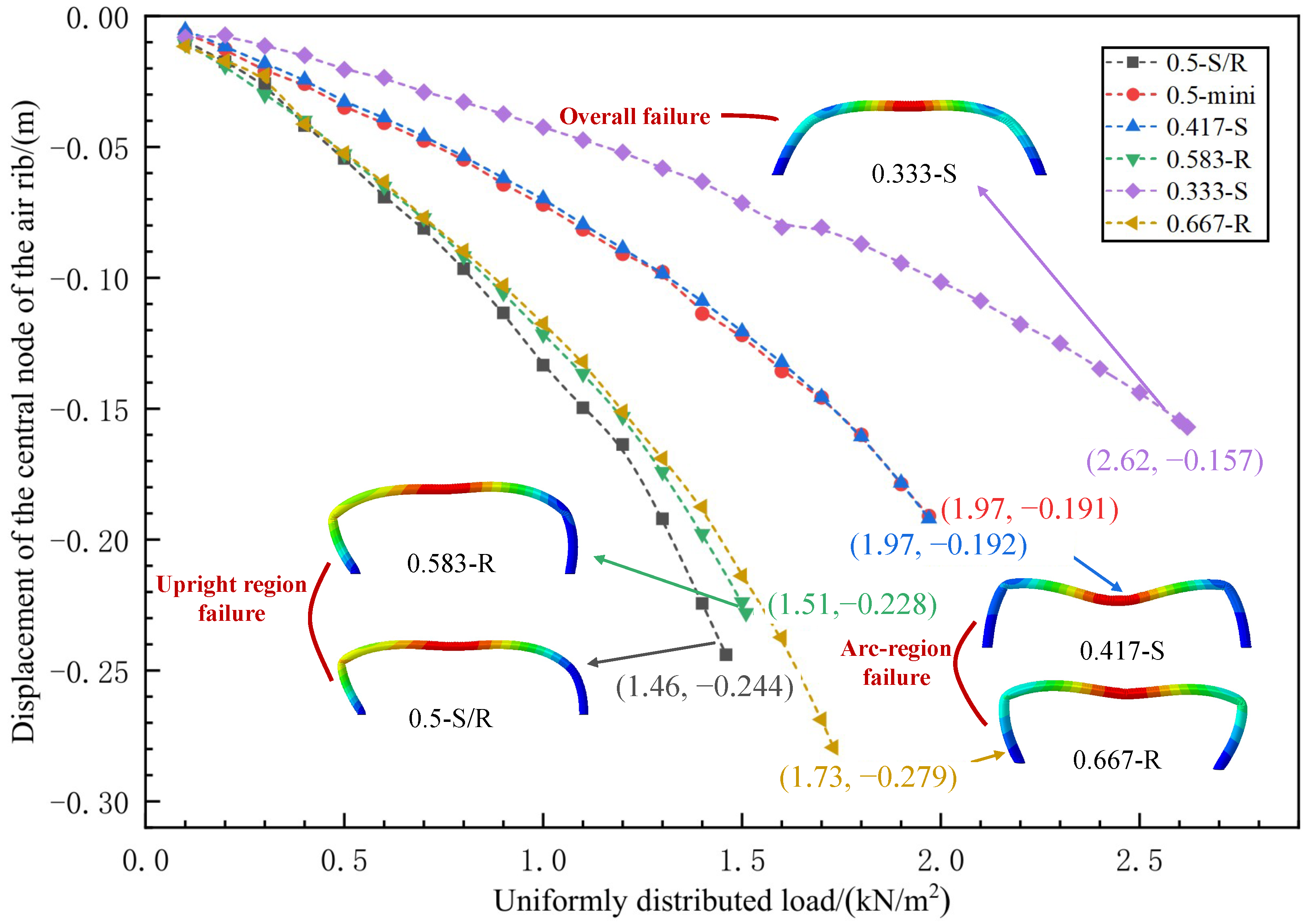
2.4. The Failure Mechanism Analysis of Air Ribs Under Vertical Loading

As a typical annular flexible body, the air rib deforms differently under external loads. The middle section of the air rib flattens, while the end sections spread outward during the deformation process. The stress concentration occurs in the bending regions. To investigate the mode of air ribs under critical loads, the deformation of five air ribs (0.333-S, 0.417-S, 0.5-S/R, 0.583-R, and 0.667-R) is analyzed. The structural model and loading mode are illustrated in Figure 4. A uniformly distributed vertical load is applied to the upper surface of the air ribs. The load is applied on the ribs gradually and calculated by the explicit dynamic method [23]. This approach minimizes oscillations and stabilizes the model prior to further analysis. During the compression process, the rib gradually deforms downward until it reaches its lowest point. The load corresponding to this lowest position is defined as the critical load.
Figure 5 demonstrates the stress distribution of different air ribs under critical load. The rib named 0.333-S presents a significantly smoother structural shape, and the maximum stress is 18.43 MPa. The stress distributes uniformly and the stress concentrates on a small area. For the other air ribs, there is stress concentration at the top and bending regions. In order to explain the bearing and deformation performance, the air ribs are divided into two parts by the stress concentration regions. The upright region near the root of the air rib is bare of deflection, and the arc-like middle section suffers large deformation. The arc-like region is similar to an arc under radial load, while the upright region near the root behaves like an upright cylinder. With the increase in the load, the arc-like region and upright region can be seen as two independent bearing parts. The upright region is simplified as a thin-walled cylinder, which is subjected to eccentric load. The arc-like region is simplified as a rod that is hinged at both ends. With the increase in the load, there will be two failure mechanisms. If the stiffness of the upright region is larger than that of the arc-like region, the middle of the arc-like region is crushed first and the upright region keeps straight. If the stiffness of the upright region is less than that of the arc-like region, the upright region goes down and the structure collapses from the bending stress concentration regions. The competition between the upright region and arc-like region can be analyzed by the classical theory.
The parameter schematic of the arch structure is shown in Figure 6. When the load is added to a circular arch, the buckling load is influenced by its initial radius of curvature and the covered angle. The covered angle θ , initial radius of curvature R, and the ovality of the arch n are calculated as follows:
θ = 180 S π R , R = r ( 1 + n ) , n = r max r min r avg
where S is the length of the fitted circular arc of the mid-section of the rib, r is the radius of the fitted arc, r max is the maximum distance and r min is the minimum distance from the rib nodes to the center of the fitted circle, and r avg is the average distance from the rib nodes to the center of the fitted circle.
The intermediate section is not a perfect circle; the concept of ovality is introduced to represent the actual geometry of the air rib more accurately. The arc length S and radius r of the arc-like region are obtained by fitting the node data of the rib under critical load. As shown in Table 2, the θ of the 0.417-S configuration is the smallest, and the value is 63.8°. The θ of the 0.583-R configuration is the largest, and the value is 86.2°. A lower θ and a larger radius of curvature suggest that the air rib possesses a gentler arc segment. This gentler curvature enables a more uniform distribution of stress under external loads, thereby reducing stress concentrations and delaying local buckling and instability. Conversely, a higher θ implies that the air rib has a steeper curvature and a smaller radius of curvature. This sharper curvature is more prone to causing localized stress concentrations under external loads. The stress concentration in the curved sections leads to premature buckling and instability. Therefore, θ can be set as an effective method for assessing load-bearing performance. The relationship between the buckling load, radius of curvature, and the covered angle is analyzed by previous studies, and the buckling load decreases with the increase in the θ [29]. For the arc-like region, the buckling load q of ribs is ranked as q 0.417 - S > q 0.5 - S / R > q 0.667 - R > q 0.583 - R .
For the upright region of air ribs, the critical failure load F is calculated by Formula (2) as a thin-walled cylinder under axial load [30]:
F c r = A i 2 L cos α k E δ Φ , k = Φ e Φ
where F c r is the critical instability load of the thin-walled cylinder, E is the Young’s modulus of the thin-walled cylindrical material, L is the length of the thin-walled cylinder, Φ is the equivalent diameter, δ is the thickness of the thin wall, A is the cross-sectional area, i is the inertia radius, e is the eccentricity of the load, and k is the eccentricity effect coefficient. The initial geometry of the air ribs plays a significant role in determining the load deformation of the upright region. It can be seen from Formula (2) that the load-bearing capacity of the upright cylindrical structure is influenced by the material, length, and eccentricity of the upright segment and the distribution of external loads. The initial geometry of the air ribs plays a significant role in determining the load deformation of the upright region. As the k is smaller, the upright region is closer to an ideal cylindrical form and can bear more load effectively in the vertical direction. The parameter schematic of the upright region is shown in Figure 7. The load is added on the top of the arc-like region and transferred to the upright region, so there is an angle ( α ) to describe the effective load. The materials of ribs studied in this paper, namely A, i, E, and δ , are the same. So, F is proportional to the value of k / L cos α , which is defined as M. The values of M are shown in Table 3. The M of the rib named 0.417-S is the largest and that of the rib named 0.5-S/R is small. For the upright region, the critical failure load (F) of ribs is ranked as F 0.417 - S > F 0.667 - R > F 0.583 - R > F 0.5 - S / R .
According to the segmentation failure competition mechanism proposed above, the critical bearing load (N) of the ribs is based on the min { q , F } . Figure 8 provides the relation between the load and deformation of ribs and the destabilized structural configurations of air ribs under failure loads. Initially, air ribs go downward linearly with the increase in the vertical load, which is crucial to evaluate the bearing capacity of ribs. With the increase in the load, the displacement increases disproportionately, the structure approaches a buckled state, and obtains an impending structural failure. For the air rib named 0.333-S, it has a similar pattern of stress distribution, and the critical load is 2.62 kN / m 2 , meaning it provides greater resistance to buckling and instability. It can be seen that the critical bearing load of the 0.5-S/R is the minimum and lower than 1.46 kN / m 2 . When the load is 1.46 kN / m 2 , the stress distributes uniformly initially. With the increase in the load, the stress concentrates around the waist region of the rib locally, and the structure enters an unstable state when the load is 1.47 kN / m 2 . The q 0.5 - S / R is large, but the F 0.5 - S / R is the minimum, and the critical bearing load N 0.5 - S / R is based on the value of F 0.5 - S / R . So, the rib named 0.5-S/R fails at the upright region, which is consistent with the structural form of the rib in the failure condition. The q 0.667 - R and q 0.5 - S / R are similar, but F 0.667 - R is larger than F 0.583 - R and F 0.5 - S / R . The critical bearing load ( N 0.5 - S / R ) is based on the value of q 0.667 - R , and it is 1.73 kN / m 2 . Then, the rib named 0.667-R fails at the arc-like region, which can be seen in Figure 8. In this paper, the variation of buckling load (q) or critical failure load (F) with different structures are studied, but the specific value of buckling load (q) and critical failure load (F) are not calculated. The failure mechanism of the ribs named 0.417-S and 0.583-R are confirmed with the deformation results at structural failure. For the rib named 0.417-S, q 0.417 S and F 0.417 S are large, and it fails at the middle of the arc-like region; so, q 0.417 - S is smaller than F 0.417 - S , and the critical bearing load ( N 0.417 - S ) is 1.97 kN / m 2 . The q 0.583 - R and F 0.583 - R of the rib named 0.583-R are smaller than those of the rib named 0.667-R. The critical bearing load ( N 0.583 - R ) is 1.51 kN / m 2 , based on the value of F 0.583 - R , and fails at the upright region. By the analysis of the five types of ribs, the segmentation failure competition mechanism can be used to evaluate the critical bearing load.

3. The Load-Bearing Performance of Tents with Different Rise–Span Ratios

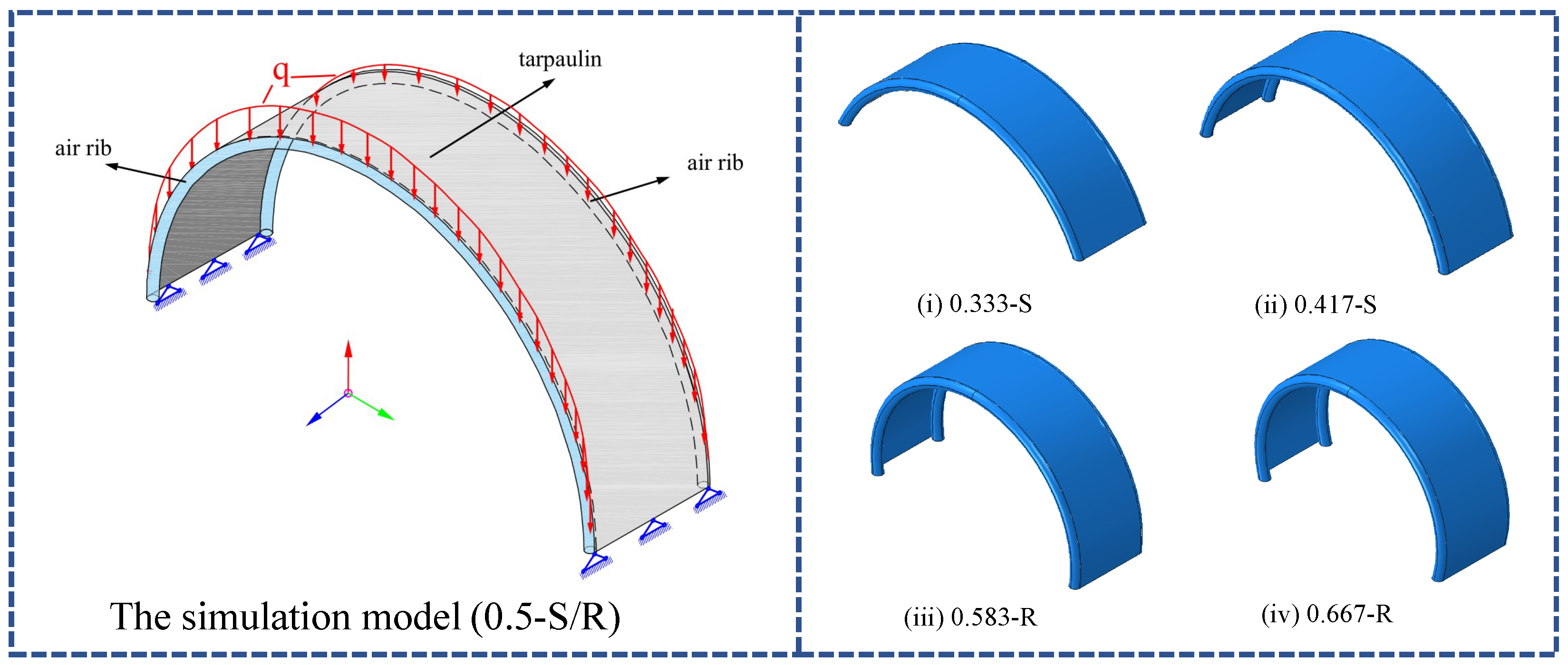
3.1. The Simulation Model of the Tent Under Load

The previous analysis highlights that the rise–span ratio of the air rib has an important impact on the bearing capacity. Due to the large curvature variation at the ends, the air-ribbed tent is vulnerable to wind-induced damage, making the ends a critical component in engineering applications. The ribs support the structure, the tent fabric transfers the load, and the wind ropes help reduce structural deformation. The interaction of these three elements ensures the proper functioning of the tent. To improve load-bearing capacity, four tents are designed and the end ribs are set to be 0.333-S, 0.417-S, 0.583-R, and 0.667-R.
As depicted in Figure 9a, the tent that spans 8 m in width and 18 m in length is supported internally by ten air ribs. The cross-sectional diameter of each rib is 0.3 m, and the radius of the central rib is 4 m, with a distance of 2 m between each rib. These air ribs are used to resist wind loads and play a crucial role in maintaining structural integrity. The air ribs and the tarpaulin are bonded by a high-strength adhesive. Wind ropes, with a radius of 0.009 m and an elastic modulus of 2820 MPa, are installed at 45° to the ground to enhance stability. The tarpaulin and air ribs of the tent are constructed from two composite materials. The density of the tarpaulin is 970 kg / m 3 , and the tarpaulin thickness is 2.8 × 10 4 m. The Young’s modulus is 1040 MPa, and the Poisson’s ratio is 0.35. The wind angle along the positive z-axis of the tent is defined as 0°, and the wind angle along the positive x-axis is defined as 90°. The improved tent model is shown in Figure 9b.

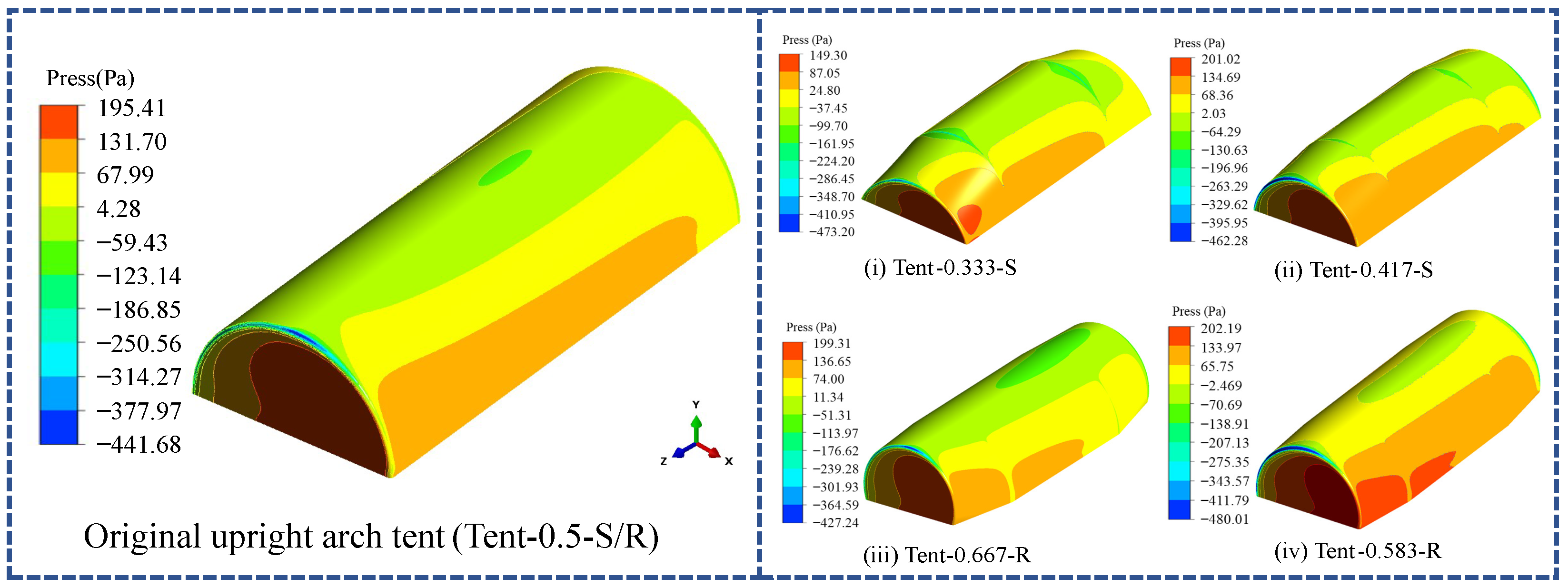
3.2. The Analysis of the Distribution of Wind Pressure

The distribution of the wind pressure on the tent is calculated by Fluent. To minimize the influence of boundaries on the wind pressure, the distance between the inlet and the boundary of the tent is set to five times the length of the tent, and the distance between the outlet and the boundary of the tent is set to ten times the length of the tent. The computational domain is set to be 270 m × 180 m × 40 m , ensuring the blockage ratio is lower than 3% [31,32]. The inlet is configured as the velocity inlet, and symmetry conditions are applied to the top and side boundaries to maintain environmental continuity. The bottom boundary is treated as a non-slip wall to replicate ground interaction, while the outlet is free, preventing the back pressure. The flow field of the tent is meshed based on the study by He et al. [33]. An unstructured grid is used in the immediate vicinity of the tent ( 20 m × 20 m × 20 m ) to accurately capture the complex flow behavior around the structure. In contrast, a structured grid is used in the outer regions to enhance computational efficiency. The specific mesh configuration is illustrated in Figure 10. The simulation employs a total of approximately 4.6 million grids, achieving a balance between detailed accuracy and computational feasibility.
According to the Technical Specification for Membrane Structures (CECS 2015) [28], the conditions for the inlet of the wind field are based on a 50-year return period. The wind velocity is 20.7 m/s at a height of 10 m, which corresponds to a fresh gale [34]. The environment is classified as Category B terrain, with a ground roughness coefficient of 0.15. A power function is used to simulate the variation of wind speed with height, which is defined as follows:
U Z = U G Z Z G β
where Z G is the gradient wind height, β is the ground roughness coefficient, U G is the gradient wind speed, and U z is the wind speed at a height z above the ground.
Figure 11 shows the distribution of wind pressure on the surface of the tents. The maximum pressure of Tent-0.333-S is 149.3 Pa, which is the smallest, while that of Tent-0.583-R is 202.19 Pa, the largest among the five structures. The maximum pressure appears at the upwind angle face, making the end rib the main component supporting the entire tent. Reducing the rise of the end ribs significantly affects the enlargement of the positive pressure area on the windward side, compared to reducing the span and creating negative pressure areas at the top of the tent. The top of the tent is under the wind suction, the end rib in the upwind direction is affected by the wind pressure, and the one in the downwind direction is affected by the wind suction. However, based on the wind pressure results alone, aside from slight changes in the distribution, the modifications of the end ribs have not effectively reduced the maximum wind pressure values on the tent.

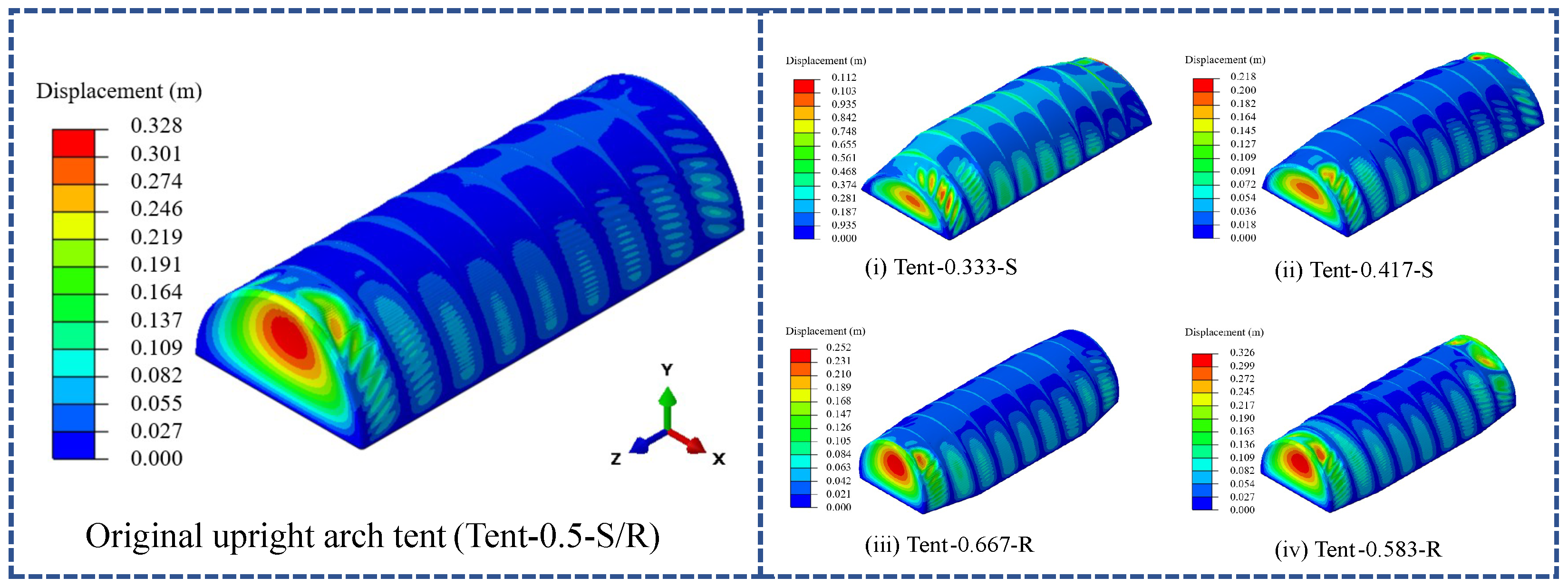
3.3. The Analysis of the Deformation of the Tent

The load applied on the tent consists of gravity and the wind load, which is derived from CFD simulation results. Membrane structures are typically lightweight and have low natural frequencies. They produce large deformation under wind load, and the relationship between the load and deformation is nonlinear [35,36]. An explicit dynamics algorithm is used to simulate the structural response accurately. The bottom nodes of the tent are fixed in all translational directions when it is established on the ground. The tent is primarily modeled as a membrane due to its extreme thinness, resulting in negligible bending stiffness. As such, it cannot withstand the bending forces. Additionally, the wind ropes are modeled as truss elements, and the pre-tensioned stress of the wind ropes is 100 Pa. The model consists of 164,942 elements and 165,329 nodes, providing a detailed simulation of the tent’s behavior under load conditions. The analysis is conducted over a duration of 50 s to ensure the accuracy of the computational results.
The wind pressure is loaded on the tarpaulin, which deforms and transfers the force to the internal air rib through the bonding strip. Figure 12 illustrates the deformation of the air ribs in different models. Tent-0.5-S/R shows significant deformation at the end air rib on the windward side with a maximum displacement of 0.268 m. The maximum deformation of Tent-0.667-R and Tent-0.583-R also appears at the top of the end air rib on the windward side. For Tent-0.333-S and Tent-0.417-S, the maximum deformation occurs at the top of the end air rib on the leeward side, with values of 0.125 m and 0.134 m, respectively. The influence of the rise–span ratio on the bearing performance under pressure can be seen from the deformation. For example, the rib named 0.333-S has the best bearing performance under pressure; so, the deformation of the end rib on the windward side decreases, and the maximum deformation appears at the end rib on the leeward side.
The deformation of the tarpaulin determines the usable interior space. Figure 13 shows the deformation of the tarpaulin in five types of tents. The maximum displacement of the five models occurs at the center of the end face. The tents sorted by the maximum displacement are Tent - 0.333 - S < Tent - 0.417 - S < Tent - 0.667 - R < Tent - 0.583 - R < Tent - 0.5 - S / R . For Tent-0.333-S, the maximum displacement is 0.112 m, which is reduced by 65.8% compared with that of Tent-0.5-S/R. These results indicate that the structural stiffness of the air ribs is a critical factor affecting the tent’s load-bearing performance. Changing the rise and span of the end ribs effectively improves the load distribution on the tarpaulin and enhances the tent’s load-bearing performance.

4. Conclusions

Air ribs are the critical components of tents. The impact of the rise–span ratio on the stiffness and load-bearing performance of air ribs under vertical load was studied by simulation. The rib can be classified into upright and arc-shaped regions by the deformation region. The segmentation failure competition mechanism was proposed to explain the buckling behavior of ribs. When the ratios are 0.417 and 0.667, the air ribs also exhibit arc-region failure; when the rise–span ratios are 0.5 and 0.583, the air ribs undergo upright region failure; when the rise–span ratio is 0.333, the upright and arc regions fail simultaneously; so, the critical load is the maximum, and the value is 2.62 kN / m 2 , which is 78% higher than that of the tent whose rise–span ratio is 0.5. Based on the findings from the rib analysis, the tents of different ribs were designed. The tent shows the highest load-bearing capacity when the rise–span ratio of the end air ribs is 0.333, which is consistent with the analysis results of the air ribs.
This research provides valuable insights for optimizing air rib performance. Future studies could further explore the effects of pressure and the material of air ribs on load-bearing performance to achieve an optimal balance between capacity and spatial efficiency.

Author Contributions

Conceptualization, Y.L. (Ying Liu) and S.L.; methodology, Y.L. (Ying Liu) and S.L.; software, S.L. and Y.L. (Yanru Li); validation, Y.L. (Ying Liu); formal analysis, Y.L. (Ying Liu), S.L. and J.Z.; investigation, Y.L. (Ying Liu) and S.L.; resources, J.Z.; data curation, S.L.; writing—original draft preparation, Y.L. (Ying Liu) and S.L.; writing—review and editing, Y.L. (Ying Liu), S.L. and Y.L. (Yanru Li); visualization, Y.L. (Ying Liu) and Y.L. (Yanru Li); supervision, Y.L. (Ying Liu) and J.Z.; project administration, Y.L. (Ying Liu) and J.Z.; funding acquisition, Y.L. (Ying Liu) and S.L. All authors have read and agreed to the published version of this manuscript.

Funding

This research was funded by the Special Funds of the Cultivation Program of Beijing University of Civil Engineering and Architecture, grant number X24020.

Institutional Review Board Statement

Not applicable.

Informed Consent Statement

Not applicable.

Data Availability Statement

The original contributions presented in this study are included in the article. Further inquiries can be directed to the corresponding author.

Conflicts of Interest

The authors declare no conflicts of interest.

References

  1. Motevalli, M.; Uhlemann, J.; Stranghöner, N.; Balzani, D. Geometrically nonlinear simulation of textile membrane structures based on orthotropic hyperelastic energy functions. Compos. Struct. 2019, 223, 110908. [Google Scholar] [CrossRef]
  2. Kamaliya, P.K.; Upadhyay, S.H. Inflatable antenna structures: Deployment analysis of torus bounded Z-fold scalable planar membrane reflector. Thin-Walled Struct. 2023, 191, 111061. [Google Scholar] [CrossRef]
  3. López, I.; Piquee, J.; Bucher, P.; Bletzinger, K.-U.; Breitsamter, C.; Wüchner, R. Numerical analysis of an elasto- flexible membrane blade using steady-state fluid–structure interaction simulations. J. Fluids Struct. 2021, 106, 103355. [Google Scholar] [CrossRef]
  4. Xu, J.; Zhang, Y.; Yu, Q.; Zhang, L. Analysis and design of fabric membrane structures: A systematic review on material and structural performance. Thin-Walled Struct. 2022, 170, 108619. [Google Scholar] [CrossRef]
  5. Takadate, Y.; Uematsu, Y. Steady and unsteady aerodynamic forces on a long-span membrane structure. J. Wind Eng. Ind. Aerodyn. 2019, 193, 103946. [Google Scholar] [CrossRef]
  6. Yang, T.; Luo, M.; Zou, Z.; Ma, P. Mechanical properties of the surface membrane of lattice spacer-fabric flexible inflatable composites. Text. Res. J. 2022, 92, 1088–1097. [Google Scholar] [CrossRef]
  7. Zhou, Y.; Li, Y.; Yoshida, A. Effect of added mass on wind-induced vibration of a circular flat membrane by wind tunnel tests. Int. J. Struct. Stab. Dyn. 2018, 18, 1850156. [Google Scholar] [CrossRef]
  8. Liu, C.; Pan, R.; Deng, X.; Xie, H.; Liu, J.; Wang, X. Random vibration and structural reliability of composite hyperbolic–parabolic membrane structures under wind load. Thin-Walled Struct. 2022, 180, 109878. [Google Scholar] [CrossRef]
  9. Sun, X.; Kandel, A.; Wu, Y. Investigation on wind tunnel experiment of oval-shaped arch-supported membrane structures. J. Wind Eng. Ind. Aerodyn. 2020, 206, 104371. [Google Scholar] [CrossRef]
  10. Kandel, A.; Sun, X.; Wu, Y. Wind-induced responses and equivalent static design method of oval-shaped arch-supported membrane structure. J. Wind Eng. Ind. Aerodyn. 2021, 213, 104620. [Google Scholar] [CrossRef]
  11. Chen, Z.; Liu, C.; Li, D.; Liu, J.; Deng, X.; Luo, C.; Zhou, G. Study on Wind-Induced Dynamic Response and Statistical Parameters of Skeleton Supported Saddle Membrane Structure in Arching and Vertical Direction. Buildings 2024, 14, 1339. [Google Scholar] [CrossRef]
  12. Liu, C.; Deng, X.; Zheng, Z. Nonlinear wind-induced aerodynamic stability of orthotropic saddle membrane structures. J. Wind Eng. Ind. Aerodyn. 2017, 164, 119–127. [Google Scholar] [CrossRef]
  13. Chen, Z.; Wei, C.; Li, Z.; Zeng, C.; Zhao, J.; Hong, N.; Su, N. Wind-induced response characteristics and equivalent static wind-resistant design method of spherical inflatable membrane structures. Buildings 2022, 12, 1611. [Google Scholar] [CrossRef]
  14. Shi, J.-X.; Wu, Z.; Tsukimoto, S.; Shimoda, M. Design optimization of cable–membrane structures for form-finding and stiffness maximization. Compos. Struct. 2018, 192, 528–536. [Google Scholar] [CrossRef]
  15. Xue, S.; Li, X.; Li, X.; Dezhkam, M. Automated design of cable-net structures with multi-objective state. Autom. Constr. 2024, 160, 105288. [Google Scholar] [CrossRef]
  16. Marbaniang, A.L.; Kabasi, S.; Ghosh, S. Interactive exploration of tensile membrane structures for conceptual and optimal design. Structures 2024, 60, 105983. [Google Scholar] [CrossRef]
  17. Nguyen, T.N.; Dang, L.M.; Lee, J.; Nguyen, P.V. Load-carrying capacity of ultra-thin shells with and without CNTs reinforcement. Mathematics 2022, 10, 1481. [Google Scholar] [CrossRef]
  18. Zheng, L.; Xu, J.; Li, F.; Zhang, J.; Su, R.; Wang, J.; Liu, Y.; Ru, Y. Analysis of Mechanical Properties of Air-Ribbed Skeleton Membrane Structure. Appl. Sci. 2023, 13, 9545. [Google Scholar] [CrossRef]
  19. Fan, B.-L.; Shi, M.-Y.; Pang, J.-C.; Wang, J.-Q.; Wang, J.-W. Research on solar power generation disaster relief tent based on inflatable structure. In Proceedings of the International Conference on Energy, Environmental and Civil Engineering (EECE 2019), Wuhan, China, 23–24 June 2019; Volume 5. [Google Scholar]
  20. Wang, C.G.; Xie, J.; Tan, H.F. Vibration simulations of a wrinkled membrane-inflated arch. J. Aerosp. Eng. 2014, 27, 414–422. [Google Scholar] [CrossRef]
  21. Liu, Y.; Ru, Y.; Li, F.; Zheng, L.; Zhang, J.; Chen, X.; Liang, S. Structural design and optimization of separated air-rib tents based on response surface methodology. Appl. Sci. 2022, 13, 55. [Google Scholar] [CrossRef]
  22. Guo, X.; Li, Q.; Zhang, D.; Gong, J. Structural behavior of an air-inflated fabric arch frame. J. Struct. Eng. 2016, 142, 04015108. [Google Scholar] [CrossRef]
  23. Malm, C.G.; Davids, W.G.; Peterson, M.L.; Turner, A.W. Experimental characterization and finite element analysis of inflated fabric beams. Constr. Build. Mater. 2009, 23, 2027–2034. [Google Scholar] [CrossRef]
  24. Xue, Z.M.; Wang, C.G.; Kang, J.T.; Tan, H.F. Buckling analysis of an inflated arch including wrinkling based on Pseudo Curved Beam model. Thin-Walled Struct. 2018, 131, 336–346. [Google Scholar] [CrossRef]
  25. Clapp, J.D.; Young, A.C.; Davids, W.G.; Goupee, A.J. Bending response of reinforced, inflated, tubular braided fabric structural members. Thin-Walled Struct. 2016, 107, 415–426. [Google Scholar] [CrossRef]
  26. Roekens, J.; De Laet, L.; Mollaert, M.; Luchsinger, R. Experimental and numerical investigation of a tensairity arch. Thin-Walled Struct. 2016, 105, 112–120. [Google Scholar] [CrossRef]
  27. Zhao, R.; Li, X.; Wang, W.; Xue, S.; Dou, F. Bending performance of highly pressured inflatable membrane arches. Eng. Struct. 2025, 328, 119716. [Google Scholar] [CrossRef]
  28. CECS 158-2015; China Association for Engineering Construction Standardization. Chinese Technical Specification for Membrane Structures: Beijing, China, 2015.
  29. Pi, Y.L.; Bradford, M.A.; Tin-Loi, F. Flexural-torsional buckling of shallow arches with open thin-walled section under uniform radial loads. Thin-Walled Struct. 2007, 45, 352–362. [Google Scholar] [CrossRef]
  30. Yao, N.; Wang, C.; Lu, X.; Du, J. A Method for Calculating the Critical Buckling Load of a Thin-Walled Cylindrical Shell. CN112,364,461B, 19 August 2022. [Google Scholar]
  31. Wijesooriya, K.; Mohotti, D.; Lee, C.-K.; Mendis, P. A technical review of computational fluid dynamics (CFD) applications on wind design of tall buildings and structures: Past, present and future. J. Build. Eng. 2023, 74, 106828. [Google Scholar] [CrossRef]
  32. Fu, W.; Yang, H.; Jia, J. Fluid vibration analysis of large-span skeletal membrane structures under pulsating winds. Adv. Civ. Eng. 2023, 2023, 6251962. [Google Scholar] [CrossRef]
  33. He, Y.; Zhao, Y.; Li, J. Wind vibration response analysis of air rib inflatable tent. Spat. Struct. 2021, 27, 56–61+70. [Google Scholar]
  34. GB 50009-2012; Code for Building Structure Loads. National Standards of the People’s Republic of China: Beijing, China, 2012.
  35. Gosling, P.D.; Bridgens, B.N.; Zhang, L. Adoption of a reliability approach for membrane structure analysis. Struct. Saf. 2013, 40, 39–50. [Google Scholar] [CrossRef]
  36. Wang, X.; Chu, H.; Yang, Q. Numerical analysis of wind-induced response of a wrinkled membrane. Int. J. Struct. Stab. Dyn. 2020, 20, 2050056. [Google Scholar] [CrossRef]
Figure 1. The simulation model of air ribs to calculate the stiffness.
Applsci 15 04154 g001
Figure 2. Deformation results of air rib with rise–span ratio of 0.5 under compressive load/(m).
Applsci 15 04154 g002
Figure 3. The trend of the displacement with the resisted load and stiffness.
Applsci 15 04154 g003
Figure 4. The simulation model of air ribs to calculate the critical load.
Applsci 15 04154 g004
Figure 5. Structural form and stress distribution of air ribs under critical load.
Applsci 15 04154 g005
Figure 6. The parameter schematic of the arch structure.
Applsci 15 04154 g006
Figure 7. The parameter schematic of the upright region.
Applsci 15 04154 g007
Figure 8. The displacement of the center node of the air rib varies with load.
Applsci 15 04154 g008
Figure 9. The model of air-ribbed tents ((a) The original upright arched tent structure; (b) The improved tent model).
Applsci 15 04154 g009
Figure 10. Mesh division for CFD analysis of the tent’s flow field ((a) shows the mesh distribution overview; (b) illustrates the mesh division within the tent’s flow field; (c) depicts the boundary layer mesh).
Applsci 15 04154 g010
Figure 11. The distribution of the wind pressure coefficient on the surface of the tent.
Applsci 15 04154 g011
Figure 12. The displacement of tent air ribs.
Applsci 15 04154 g012
Figure 13. The displacement of the tent tarpaulin.
Applsci 15 04154 g013
Table 1. Air rib design parameters: rise–span ratio and material properties.
Air RibRise/(m)Span/(m)Thickness /(m)Density /(Kg/m3)Elastic Modulus/(MPa)Poisson’s RatioBreaking Strength/(MPa)
0.333-S2.678 1.84 × 10 3 10104400.32120.39
0.375-S38
0.417-S3.338
0.458-S3.678
0.5-S/R48
0.542-R47.83
0.583-R46.86
0.625-R46.4
0.667-R46
0.5-mini3.57
Table 2. Shape parameters of the mid-section of the air ribs.
Air RibS/(m)r/(m)N θ
0.417-S6.645.822.48%63.8°
0.667-R6.324.963.10%70.8°
0.583-R7.134.554.24%86.2°
0.5-S/R8.155.903.74%69.6°
Table 3. Shape parameters of the upright region of the air ribs.
Air RibL/(m)e/(m)k α M
0.417-S1.810.070.7348.2°0.61
0.667-R2.090.050.8346.9°0.56
0.583-R1.840.110.6327.3°0.38
0.5-S/R2.040.120.632°0.34
Disclaimer/Publisher’s Note: The statements, opinions and data contained in all publications are solely those of the individual author(s) and contributor(s) and not of MDPI and/or the editor(s). MDPI and/or the editor(s) disclaim responsibility for any injury to people or property resulting from any ideas, methods, instructions or products referred to in the content.

