Article

Electron Beam Irradiation’s Effect on Polyaniline/LiClO4/CuO Nanocomposite: A Study of Dielectric, Conductivity and Electrochemical Properties

by
Yesappa Laxmayyaguddi
1,
Sharanappa Chapi
2,* and
Nagaraj Nandihalli
3
1
College of Agricultural Engineering, University of Agricultural Sciences, Raichur 584104, Karnataka, India
2
Department of Physics, B.M.S. College of Engineering, Bengaluru 560019, Karnataka, India
3
Critical Materials Innovation Hub, Ames National Laboratory, U.S. Department of Energy, Iowa State University, Ames, IA 50011, USA
*
Author to whom correspondence should be addressed.
Appl. Sci. 2025, 15(7), 4001; https://doi.org/10.3390/app15074001
Submission received: 22 February 2025 / Revised: 29 March 2025 / Accepted: 31 March 2025 / Published: 4 April 2025

Abstract

:
A straightforward chemical polymerization process was used to create the polyaniline/LiClO4/CuO nanoparticle (PLC) nanocomposite, which was then exposed to varying doses of electron beam (EB) radiation and studied. The FESEM, XRD, FTIR, DSC, TG/DTA, and electrochemical measurements with higher EB doses showed clear changes. The FTIR spectra of the PLC nanocomposite showed variations in the C-N and carbonyl groups at 1341 cm−1 and 1621 cm−1, respectively. After a 120 kGy EB dose, the shape changed from a smooth, uneven surface to a well-connected, nanofiber-like structure, creating pathways for electricity to flow through the polymer matrix. The EB irradiation improved the thermal stability by decreasing the melting temperature, and the XRD and DSC studies reveal that the decrease in crystallinity is attributed to the dominant chain scission mechanism. The enhanced absorption and red shift in the wavelength (from 374 nm to 400 nm) observed in the UV-Visible spectroscopy were caused by electrons transitioning from a lower to a higher energy state, with a progressive drop in the band gaps (Eg) from 2.15 to 1.77 eV following irradiation. The dielectric parameters increased with the temperature and electron beam doses because of the dissociation of the ion aggregates and the emergence of defects and/or disorders in the polymer band gaps. This was triggered by chain scission, discontinuity, and bond breaking in the molecular chains at elevated levels of radiation energy, leading to an augmented charge carrier density and, subsequently, enhanced conductivity. The cyclic voltammetry study revealed an enhanced electrochemical stability at a high scan rate of about 600 mV/s for the PLC nanocomposite with the increase in the EB doses. The I-V characteristics measured at room temperature exhibited nonohmic behavior with an expanded current range, and the electrical conductivity was estimated, using the I-V curve, to be around 1.05 × 10⁻⁴ S/cm post 20 kGy EB irradiation.

1. Introduction

Nowadays, electron beam (EB) irradiation is a useful method for sterilizing power cable insulation jacketing, preparing biomedical materials, recycling, membrane technology, and improving the thermal and mechanical properties of polymers, as well as polymerization, grafting, and modifying the physicochemical properties of polymers through vulcanization [1,2,3]. When exposed to high-energy electron beams, various polymers exhibit distinct features, with the amount of irradiation determining how much the polymer properties improve. Hence, studies on conducting polymers from various perspectives have become an extensive area of interest in research in recent years [4,5]. Many investigations have been carried out on “synthetic metals” (i.e., conducting polymers) because of their unique electronic and optical properties [6,7]. Conducting or conjugated polymers are considered advanced materials due to their special chemical and physical properties coupled with good environmental stability [8].
Conducting polymers, like polythiophene, polypropylene, polyaniline, and polypyrrole, exhibit a high specific area, high surface-to-volume ratios, and electrical conductivity, making them useful in fields, such as solid-state batteries, supercapacitors, sensors, thermoelectric, and energy storage applications [7,8,9]. These polymers are attractive due to the delocalization property of π-electrons, which achieves the maximum electrical conductivity through charge mobility along the polymer chain. This makes them applicable in various areas, such as transducers for biosensors and gas sensors, electrodes for rechargeable batteries, electromagnetic shielding, and biomedical applications [10,11,12]. Recent developments in science and technology have improved the unique physical and chemical properties of conducting polymers through irradiation. These materials are now used in various scientific areas, including detectors, dosimeters, and biotechnology, with ongoing research seeking further innovations [13,14]. Inorganic fillers added to the polymer matrix can increase the energy storage density. However, agglomeration, filler phase separation, interfacial phase regions, and matrix crystallinity are the most important elements in improving the energy storage density in these composite materials. Such issues can be addressed using EB irradiation. For example, poly(vinylidene fluoride-hexafluoropropylene) was modified with graphene nanoplatelets to improve the dielectric characteristics and energy storage density, which combines the irradiation by EB [15]. The reduced pores improved the film’s homogeneity while also improving the surface roughness and hydrophobicity, both of which are related to the dielectric characteristics and energy storage density. Polymers are extremely helpful in everyday life, and among conducting polymers, polyaniline is particularly noteworthy because of its affordable cost, easy polymerization method, and excellent thermal, chemical, and environmental stability under typical circumstances [16].
Polyaniline (PANI) aniline monomer is used more widely than other conductive polymers because of its cheapness, high polymerization efficiency, and conductivity, being unaffected by external conditions, with excellent chemical stability and good thermal properties [17]. PANI has also attracted interest because the amine nitrogen atoms may be protonated and oxidized to change their optical and electrochemical characteristics. Methods like blending with nanoparticles and treatment with salts or acids have been used to improve the conductivity and stability of polyaniline (PANI), with many researchers reporting enhanced characteristics [16,17]. To further improve the conductivity and stability, as well as to broaden the range of applications, conducting polymers have been irradiated with various sources of energy, such as X-rays [18], γ radiation [19], and EBs [20]. The ion carriers induced through radiation improve the conductivity of PANI. EB irradiation is used as a curing system. PANI and its composite active species interact with EB radiation, triggering chemical reactions that include chain scission, the production of free radicals, cross-linking, and grafting. Applying a particular dose of radiation can improve conductivity and other properties, as explained in previous reports [21,22]. An electron beam of 4.5 MeV was employed to irradiate MnO2/polyaniline (80% polyaniline and 20% MnO2) composite thin films (electrodeposited on a stainless-steel substrate) at dosages of 10 kGy, 20 kGy, and 30 kGy [23]. High-energy electron irradiation causes defects in materials, changing their morphology and characteristics. Irradiating MnO2/PANI at 20 KGy resulted in enhanced specific capacitance (840 F/g) and cyclic stability (89.2%). After electron irradiation, the specific capacitance and stability increased. Lithium perchlorate (LiClO4) is a novel bulky lithium salt characterized by significant charge delocalization, facilitating the dissociation of ions within a solvating polymer, such as poly(ethylene oxide). It demonstrates excellent chemical, electrochemical, and thermal stabilities, along with a plasticizing effect that reduces the crystallinity of the host polymer, hence facilitating ionic mobility [24]. Further, LiClO4 is cost-effective, readily purifiable, and generates highly conductive solutions with alkyl carbonate solvents, in which lithiated graphite electrodes exhibit excellent performance. Copper oxide nanoparticles (42 nm) prepared by the co-precipitation method have shown blue-shifted band gaps of 1.45 eV, and the electrical conductivity of the sample was determined to be 0.16 S/m [25]. An electrochemically deposited PANI/CuO on a glassy carbon electrode exhibited a specific capacitance of 286.35 F/g, and after 500 cycles, the specific capacitance of this nanocomposite film was 81.82% of the initial capacitance [26]. Similarly, PANI/CuO and PANI/CuO/GO nanocomposites have been investigated for their physicochemical, optical, and electrochemical properties for supercapacitor applications [27]. Therefore, the synergetic combination of the properties of polyaniline, LiClO4, and CuO in conjunction with improvements in their composite properties using electron beams is of much interest. In this study, the effects of various dosages of EB irradiation on the characteristics of a PANI/LiClO4/CuO (PLC) nanocomposite, including the structure, morphology, electrical conductivity, cyclic voltammetry (CV), and I-V, have been studied. Improvements in all related properties were observed after EB irradiation with increased EB doses.

2. Materials and Methods

2.1. Materials

Polyaniline (PANI), ammonium peroxydisulfate (APS, 98%), aniline monomer (99%), copper (II) oxide nanoparticle (NP) powder (<50 nm), hydrochloric acid (HCl, 36.46 g/mol), and lithium perchlorate (LiClO4, 106.4 g/mol, 99.9%) were purchased from Sigma-Aldrich, St. Louis, MO, USA. For the experimental investigation, double-distilled water was used.

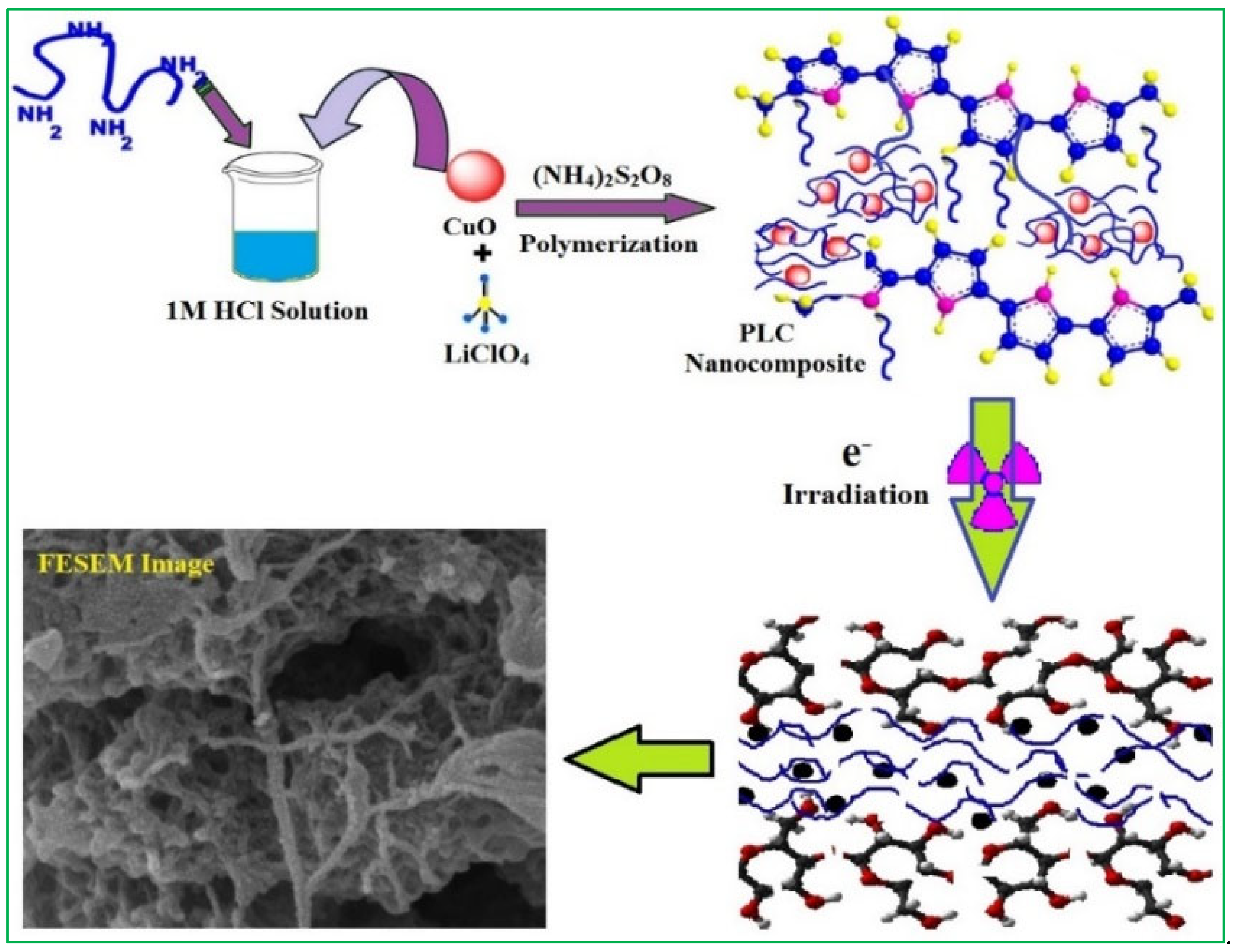
2.2. Synthesis of Polyaniline (PANI)/LiClO4/CuO Nanocomposite

The PANI/LiClO4/CuO nanocomposite was synthesized by an in situ chemical polymerization method, following the synthesis procedure explained in our previous publication [16]. In the PANI matrix, the wt.% of LiClO4 and CuO NPs were altered and coded as PLC nanocomposite. LiClO4 8 wt.% and CuO 2 wt.% were coded as PLC 10. The synthesis process and the irradiation effect on the PLC nanocomposite are presented in Scheme 1. PLC 10 was divided into 4 parts, with one part retained as a unirradiated reference sample (Unirr). The other samples were subjected to 40, 80, and 120 kGy EB irradiation dosages and labeled as PLC 40 kGy, PLC 80 kGy, and PLC 120 kGy (Section 2.4).

2.3. Instrumentation

The surface morphology was investigated using a Sigma Zeiss Field Emission Scanning Electron Microscope (FESEM) (Zeiss, Oberkochen, Germany), and chemical alterations in the 1800–600 cm−1 spectral range were examined using the FTIR (model ALPHA BRUKER, Billerica, MA, USA). A Perkin-Elmer Lambda-35 UV-Visible spectrophotometer (Waltham, MA, USA) with a computerized dual beam was used to measure the optical absorbance (A) in the wavelength range of 380–600 nm. A Wayne Kerr precision impedance analyzer 6500B (Oakley, UK) was used to test the electrical conductivity and dielectric properties in the frequency range of 24 Hz to 1 MHz at various temperatures (303–393 K).
To investigate the material’s structural phase, a Rigaku Miniflex 500 tabletop powder X-ray diffractometer (XRD) (Tokyo, Japan) was used. The Q-600 TA instruments (New Castle, DE, USA) were used to conduct differential thermal analysis (DTA), thermogravimetric analysis (TGA), and differential scanning calorimetry (DSC). The temperature was incremented from 30 to 800 °C at a heating rate of 10 °C/min, while the N2 flow rate was around 20 mL/min. The electrochemical performance of the PLC nanocomposites was determined using CV with a platinum rod serving as the counter electrode, Ag/AgCl as the reference electrode, and glassy carbon as the working electrode system in a 1 M KCl aqueous electrolyte solution at room temperature, and I-V characteristic and CV studies were conducted using an electrochemical workstation CHI 660E (Austin, TX, USA).

2.4. Electron Beam Irradiation

At LINAC, Raja Ramanna Centre for Advanced Technology—Indore, India, the PLC 10 nanocomposite was irradiated using an 8 MeV electron beam (LaB6) with 260 mA pulse current at a 31 Hz pulse repetition rate, pulse width of 10 μS, and conveyor speed of 1.3 m/min, as well as scanned at 4.0 A @ 200 msec at 40, 80, and 120 kGy dosages.

3. Results and Discussion

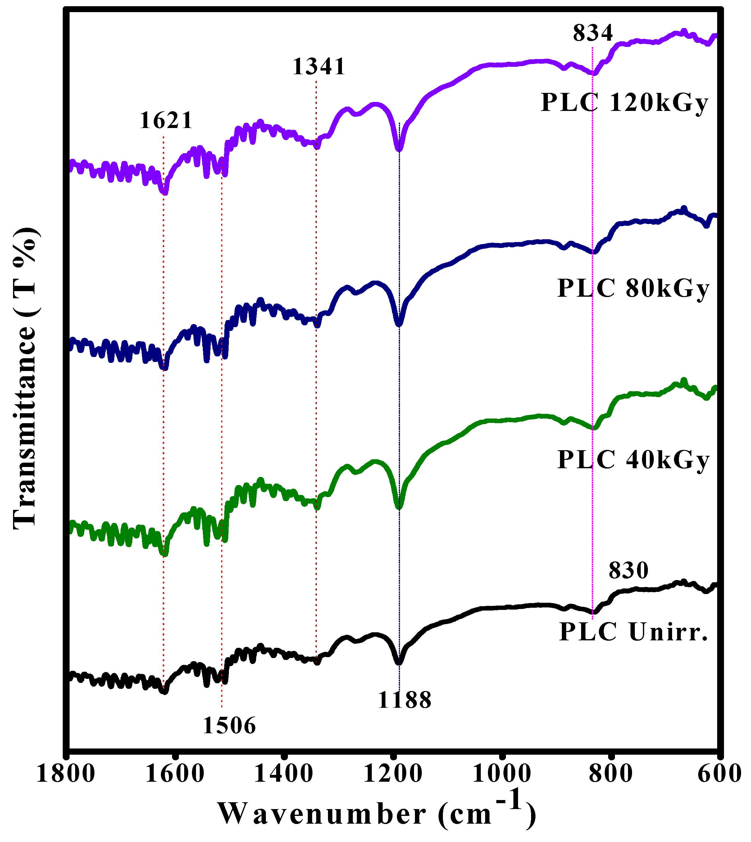
3.1. FTIR Analysis of EB-Irradiated PLC Nanocomposite

An FTIR analysis was used to determine the structural levels of the PLC nanocomposite after treatment with the various EB irradiation doses, as shown in Figure 1. The Unirr PLC nanocomposite exhibited characteristic peaks at 830, 1188, 1341, 1506, and 1621 cm−1, and all other peaks were due to the presence of dopants in the host polymer. The bands at 1341 cm−1 were assigned to C-N stretching and at 1621 cm−1 carbonyl group or C-C ring stretching vibrations. The band at 1188 cm−1 is associated with the stretching of the aromatic ring, at 830 cm−1 the C-H-plane bending vibration, and the peak at 1506 corresponds to the quinoid structure present in the main chain of the host polymer [16]. When the PLC nanocomposite was subjected to EB irradiation, the C-H-plane bending at 830 cm−1 shifted to 834 cm−1, and the intensity of all other peaks significantly increased with increases in the EB irradiation dose to 40, 80, and 120 kGy. This indicates that EB radiation may affect the molecular structure or oxidation levels through chain scission and cross-linking processes at higher EB energy [21,28], which means that the interaction improved, confirming the irradiation’s effects on the structural properties.

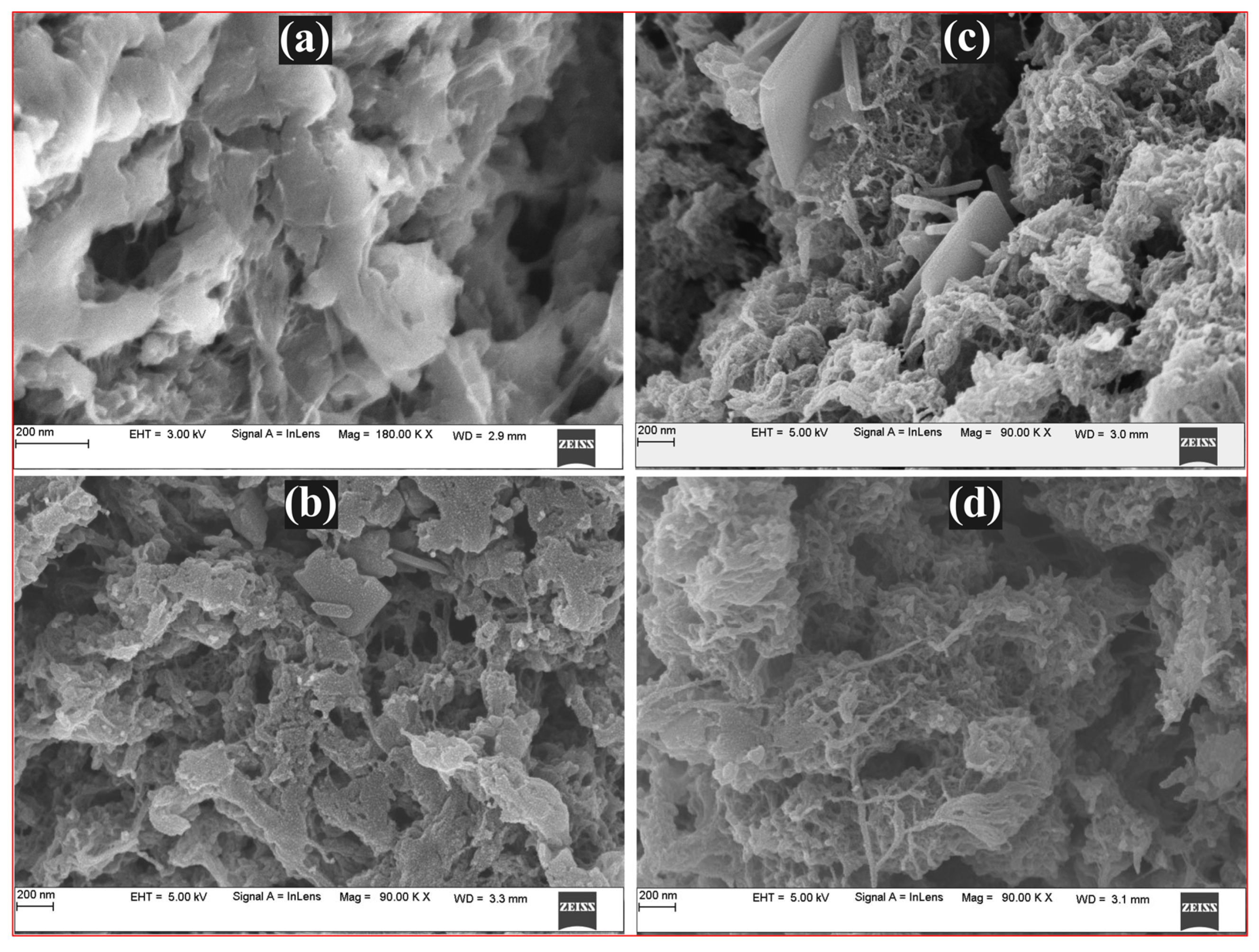
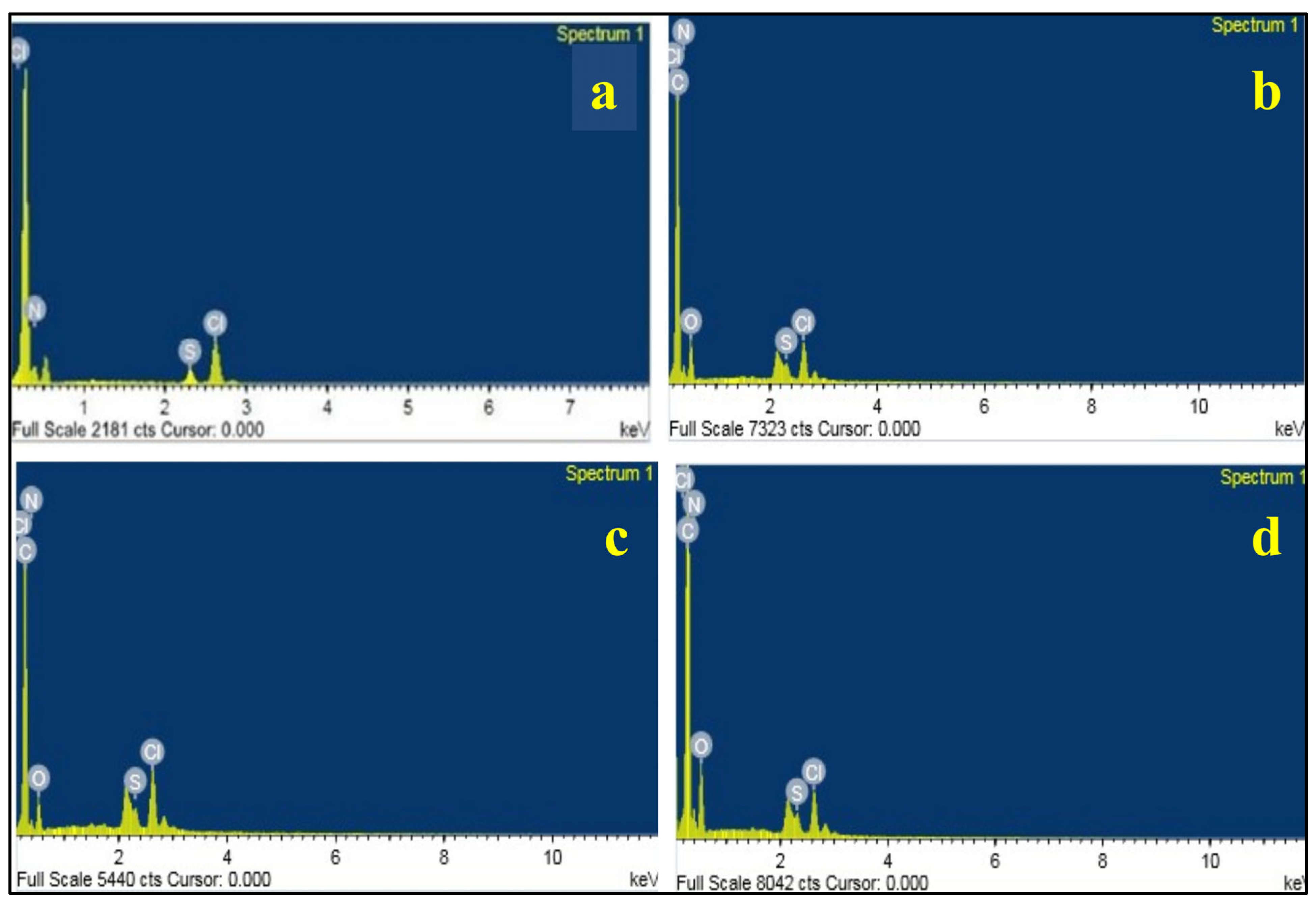
3.2. FESEM Studies of the PLC Nanocomposite

The FESEM images of Unirr and EB-irradiated PLC nanocomposite at 40, 80, and 120 kGy doses are shown in Figure 2. The morphology of the PLC nanocomposite changed following irradiation, and the variation was primarily determined by the irradiation dose. A SEM photograph of the EB-irradiated PLC nanocomposite shows a gradual change from an uneven, flat, and smooth structure of unirradiated turns into an interconnected nanofiber-like morphology (Figure 2d) that was more porous after the 120 kGy EB dose of irradiation. This dense nanofiber-like structure creates a conducting network or path within the polymer matrix.
Figure 3 illustrates the EDX spectrum of the PLC nanocomposites irradiated with the three EB dosages, providing insights into elemental identification and quantitative compositional data. The PLC nanocomposite before and after irradiation exhibited basic elements, such as N, C, Cl, S, and O elements. In addition, changes corresponding to the weight % and atom % of the abovementioned elements were observed with increases in the EB irradiation dose to 40, 80, and 120 kGy (shown in Table 1). The observed results suggest that, the element weight % and atom % varies with the EB dose because of the change in the atomic level or disturbance in the chemical bonds as a result of chain scission and/or cross-linking due to the high level of EB energy when it enters the polymer matrix. This observation confirms that there is a change in the chemical structure of the PLC nanocomposite after irradiation, which is strongly supported by the FTIR results.

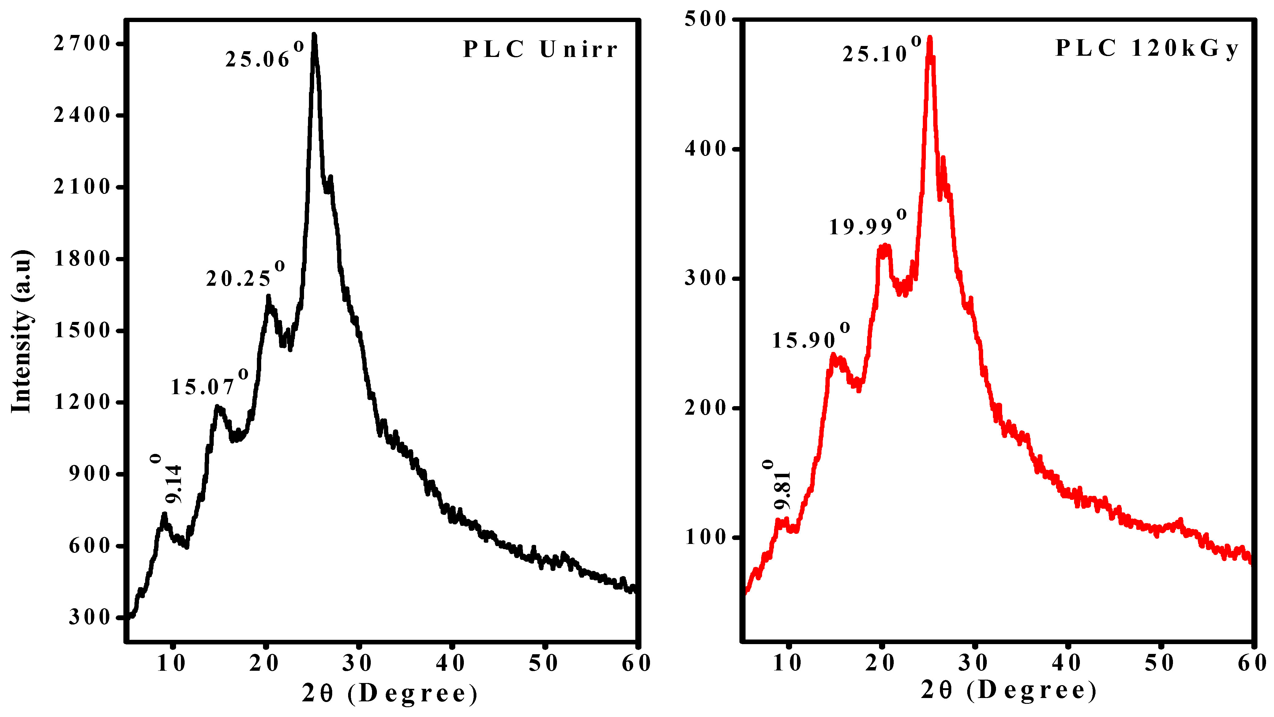
3.3. X-Ray Diffraction Study of EB-Irradiated PLC Nanocomposite

The crystalline and amorphous phases of the PLC nanocomposite were investigated using X-ray diffraction studies. The XRD patterns of the unirradiated and 120 kGy EB-irradiated PLC nanocomposite are presented in Figure 4. The available sharp peaks at 2θ = 9.14°, 15.07°, 20.25°, and 25.06°, with the corresponding crystal planes (0 0 1), (0 1 1), (1 0 0), and (1 1 0), respectively, were observed for the unirradiated PLC nanocomposite [29] and the peak positions, as well as the peak intensity, varied after irradiation, as shown in Figure 4 (120 kGy EB-irradiated). The major characteristic and high-intensity peak observed at around 2θ = 25° indicates the semicrystalline nature of the host polymer [30] in the unirradiated PLC nanocomposite. After irradiation, its relative intensity drastically decreased, and a slight variation in the peak position was observed, suggesting a decrease in the degree of crystallinity and, hence, increase in the amorphous nature of the PLC nanocomposite after the 120 kGy EB irradiation dose.
The changes in the structural parameters due to EB irradiation in the crystalline phase of the PLC nanocomposite were estimated using the Debye–Scherrer equation. For every θ value (i.e., sharp peaks), the average crystallite separation (R), strain (ɛ), crystallite size (D), and percentage of crystallinity (χ) were calculated using the following equations [30]:
R = 5 λ 8 sin θ
ε = β cos θ 4
D = k λ β cos θ
χ c = A c A c + A a × 100
where k is the shape factor (0.9), λ is the wavelength of the X-ray (0.154 Å), and Ac and Aa are the areas under crystalline and amorphous peaks, respectively. Table 2 displays the determined parameters. The estimated values represent the variation after EB irradiation. The average separation between the crystallites and the strain (ɛ) values varied, and the FWHM (β) changed with a decrease in crystallinity after irradiation. The percentage of crystallinity decreased from 79.55% in the unirradiated sample to 59.23% with a 120 kGy EB dose. This is mainly due to chain scission processes at higher dosages. These changes lead to disorders and, thus, increase the amorphous content in the polymer matrix. The decreased peak intensity noticed after irradiation is due to the reduced crystalline dimension. The slightly increased crystallite size (D) indicates that the crystalline domains embedded in the amorphous phase are responsible for this phenomenon. Defect states in the polymer matrix, caused by lattice strain from defect dislocations, lead to decreased lattice strain (ɛ). This is confirmed by the broadening or decreased peak intensity after irradiation. The interchain separation length was determined and found to decrease after irradiation, which represents the decreased hopping distance of electrons from one site to another, thereby increasing ion mobility. The calculated crystallites (R) value is 4.44 Å, which is very close to the reported value for the conductive polymer [31,32].

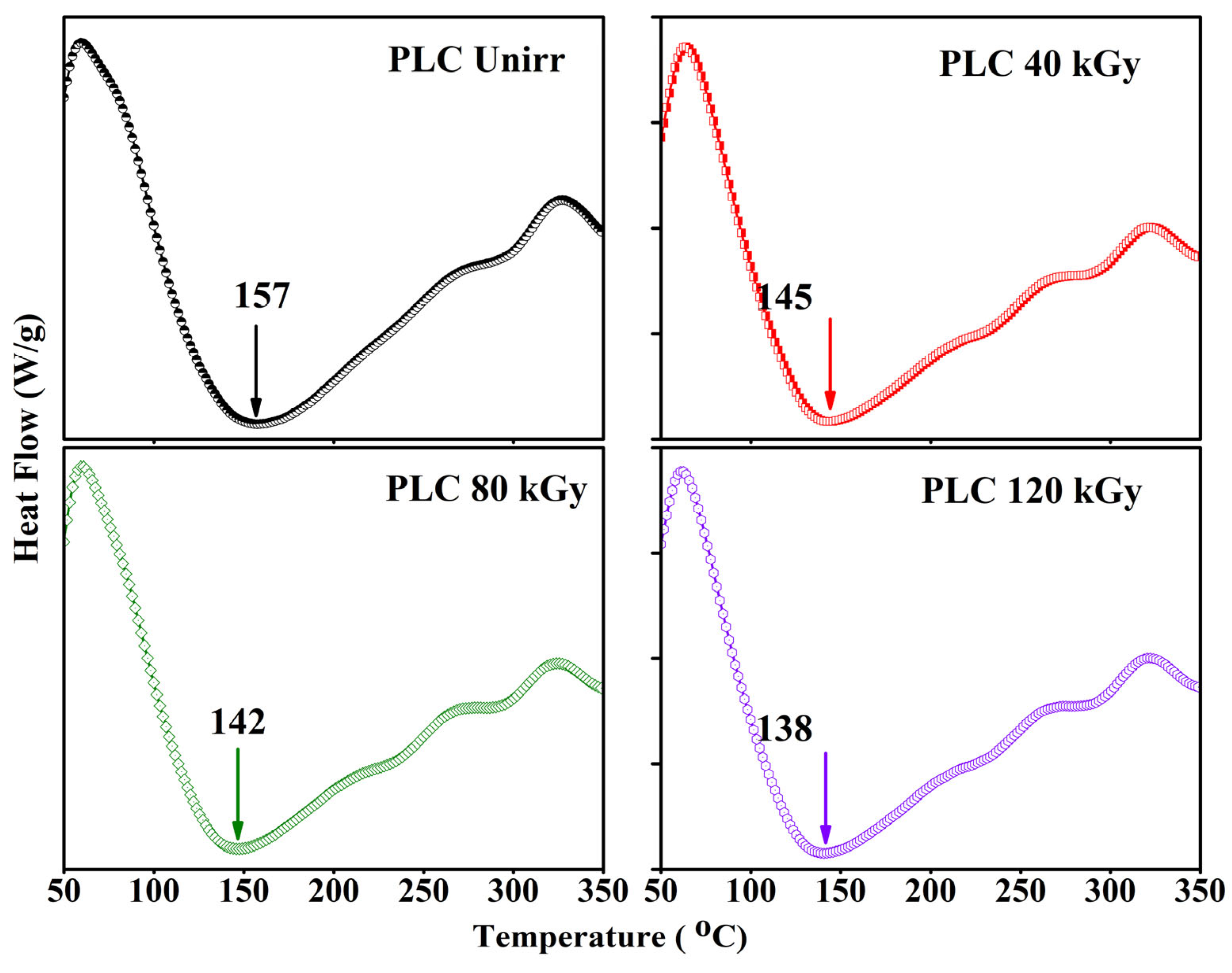
3.4. Thermal Analysis

The thermal stability and melting temperature (Tm) of Unirr and EB-irradiated PLC nanocomposite synthesized at room temperature was studied using TGA and DTA (Figure 5a,b). Weight loss was exhibited in three major stages. The first step in the weight loss observed at around 30–110 °C corresponds to the loss in moisture associated with the host polymer (PANI), and it usually shows a high loss of moisture because of its high hydroscopic nature [33]. The second step in the weight loss, observed in the range of 110–375 °C, is attributed to the start of the degradation step (fast decomposition zone) by losing the carboxylic and NH+ groups of the host polymer. This may be due to dehydration and decomposition of the chemical structure, including the content of dopants from the polymer chain. In the third stage, the degradation of the skeletal polymer chain structure and decomposition of the polymer backbone (residual decomposition zone) occurred at around 375–650 °C, during which the maximum weight loss (>90%) was observed [34]. Corresponding to decomposition temperatures of about 653, 440, 443, and 430 °C for the unirradiated at 40, 80, and 120 kGy EB doses, respectively, as shown in Figure 5b. This is mainly because of the breaking of polymer chains (i.e., chain scission) with an increase in the EB irradiation dose. The weight loss curves in the TGA leave a remarkable residue at higher temperatures. The residual temperature increased to 677, 686, 688, and 692 °C, as shown in Figure 5a (inset), with respect to the increased EB irradiation doses. This suggests changes in the molecular weight and structure as a result of free radicals formed via oxidative degradation, as reported in [35]. This may also be attributed to the cross-linking process at high irradiation doses, confirming the increased thermal stability with the EB dose. The observed results show that the PLC nanocomposite materials are highly stable at increased irradiation doses and can be used for various high-temperature applications.
Figure 6 displays the DCS curves for the PLC nanocomposites melting temperatures at various EB dosages. The melting temperature (Tm) of the Unirr composite is indicated by the endothermic peak at 157 °C, which decreased to 138 °C after a dose of 120 kGy EB irradiation. The area beneath the melting point peak decreased with the dosage, indicating a reduction in crystallinity levels. From the results, it can be noticed that a reduction in the melting temperature occurred with the EB dose. It is clear that the disordered state (amorphous) of the composite increased, and the molecular weight of the samples was reduced because of the chain scission process [36]. The chain scission process leads to the breaking off of the long polymer chains into smaller chain segments. This means that the destruction of the crystalline phase, which may be attributed to the formation of defects, thus confirms the polymer chain’s degradation and reveals an increase in the amorphicity after irradiation [35]. These observations correlate with the XRD results.

3.5. UV-Visible Spectroscopy of the PLC Nanocomposite

The UV-Vis absorption spectra of the unirradiated, as well as EB-irradiated, PLC nanocomposite are presented in Figure 7. The spectra reveal that the absorbed peaks at around 370 nm and 400 nm correspond to the excitation of benzene and the residual dopants, respectively [37]. It can be seen that the absorption spectra tended to shift toward higher wavelengths after irradiation; this means the samples underwent the radiation processes and formed fragments in the polymer matrix, which indicates that the number of dipoles increased.
The Unirr composite exhibited a peak at 374 nm that shifted to 393, 396, and 400 nm after 40, 80, and 120 kGy EB doses, respectively [9]. The shift in the wavelength confirms that the unsaturated conjugated bonds increased in the polymer nanocomposite, leading to a gradual decrease in the optical band gap after irradiation and, hence, helping to increase the conductivity. It is also noted that the absorbance increased with the irradiation dose, mainly due to the transitions of the polaron/bipolarons, which were created by the high radiation energy [38]. The observed results confirm that the optical properties of the polymer composite can be tuned by the EB irradiation.

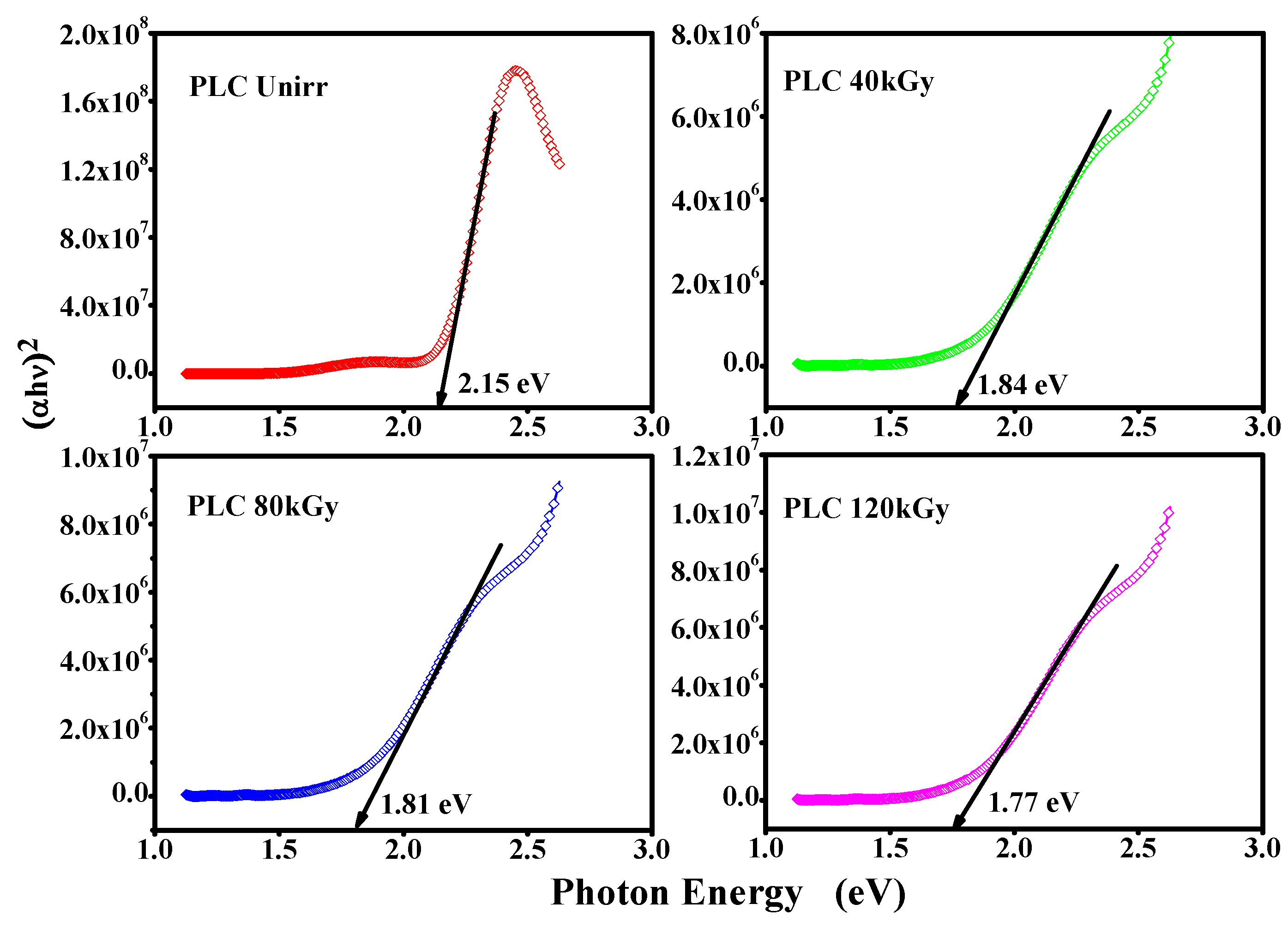
3.6. Optical Band Gap Study of the PLC Nanocomposite

The shift in the electrons from the highly occupied molecular orbital (HOMO) π-band to the lower unoccupied molecular orbital (LUMO) π*-band of electronic states is linked to optical band gaps. The absorption of photons in the medium is explained by the α(ν) absorption coefficient, which is expressed as α(ν) = 2.303 (A/d), where d is the distance into the medium (cm), and A is the absorbance, defined by A = log (I0/I), where I0 and I are the intensities of the incident and transmitted beams. For α > 104 cm−1, the PANI-based composites exhibited band gap energies within the HOMO and LUMO levels, which were calculated by the absorption coefficient using the equation [16].
α = A   h v E g h v n
where hν is the incident photon energy; h is the Planck constant; Eg is the optical band gap energy; A is a constant known as the disorder parameter, which is dependent on the composition and independent of the photon energy; and n is the power coefficient, with the value determined by the type of possible electronic transitions, i.e., 1/2, 3/2, 2, or 1/3 for direct allowed, indirect allowed, direct forbidden, and indirect forbidden, respectively [39]. The direct allowed band gaps of the PLC nanocomposite before and after EB irradiation were evaluated by extrapolating the linear portion of the curves to the energy axis for (αhν)2 = 0 from the plot of (αhν)2 versus photon energy (hν), as shown in Figure 8. The Eg values decreased with an increase in the EB dose from 2.15 eV of unirradiated to 1.84, 1.81, and 1.77 eV after 40, 80, and 120 kGy EB doses, respectively.
The decreasing trend in the Eg values with the EB dose is primarily due to the fragmentation of the long polymer chain into smaller segments and the formation of free radicals. This occurs because of the creation of traps in the polymer matrix during the chain scission process, resulting in an increase in the number of polarons at higher doses [40]. This helps form more free electrons in the conduction band, allowing them move more easily, hence increasing the conductivity. This was well correlated with the XRD analysis, which showed an increase in the amorphousness with the EB dose.

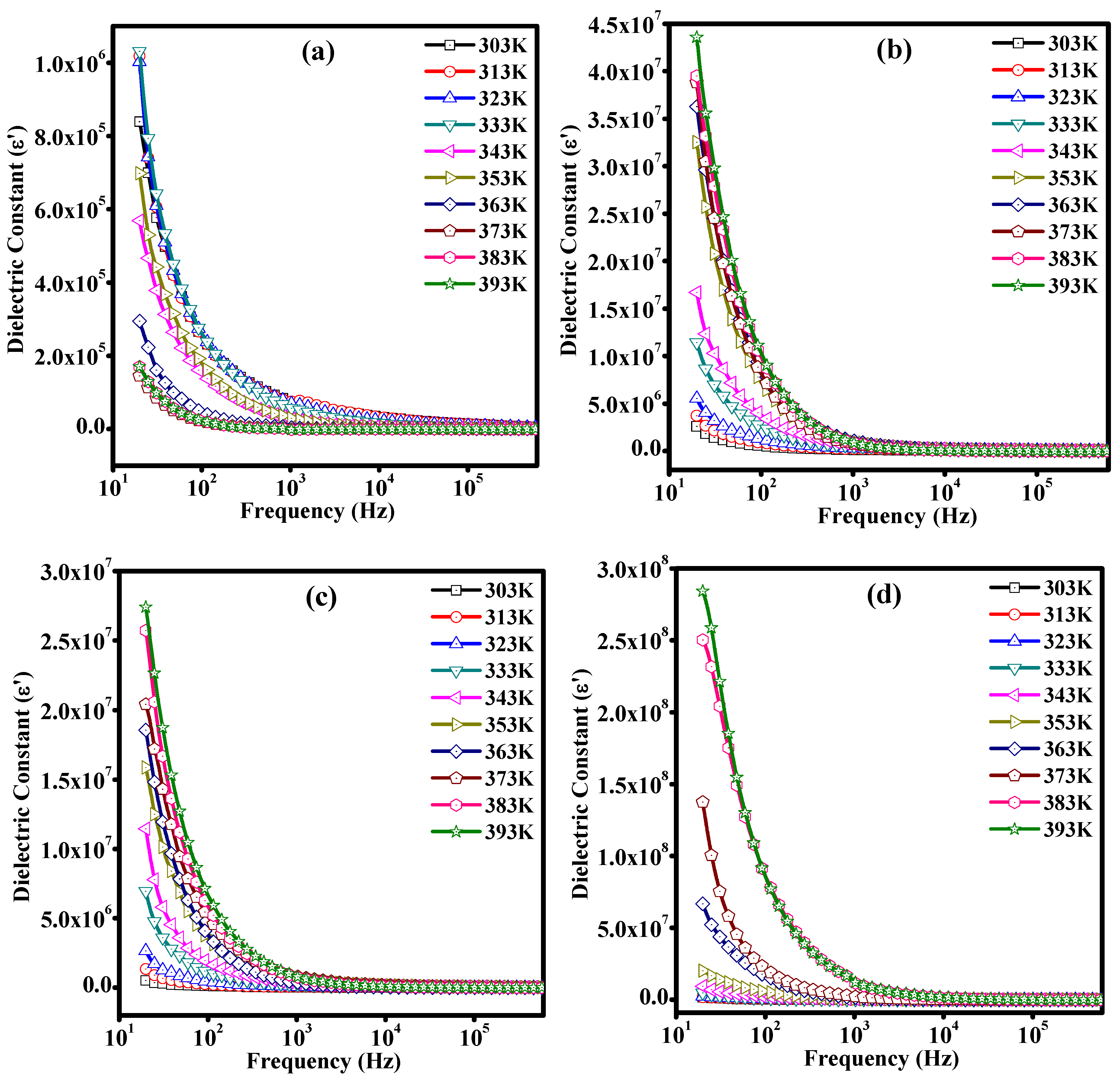
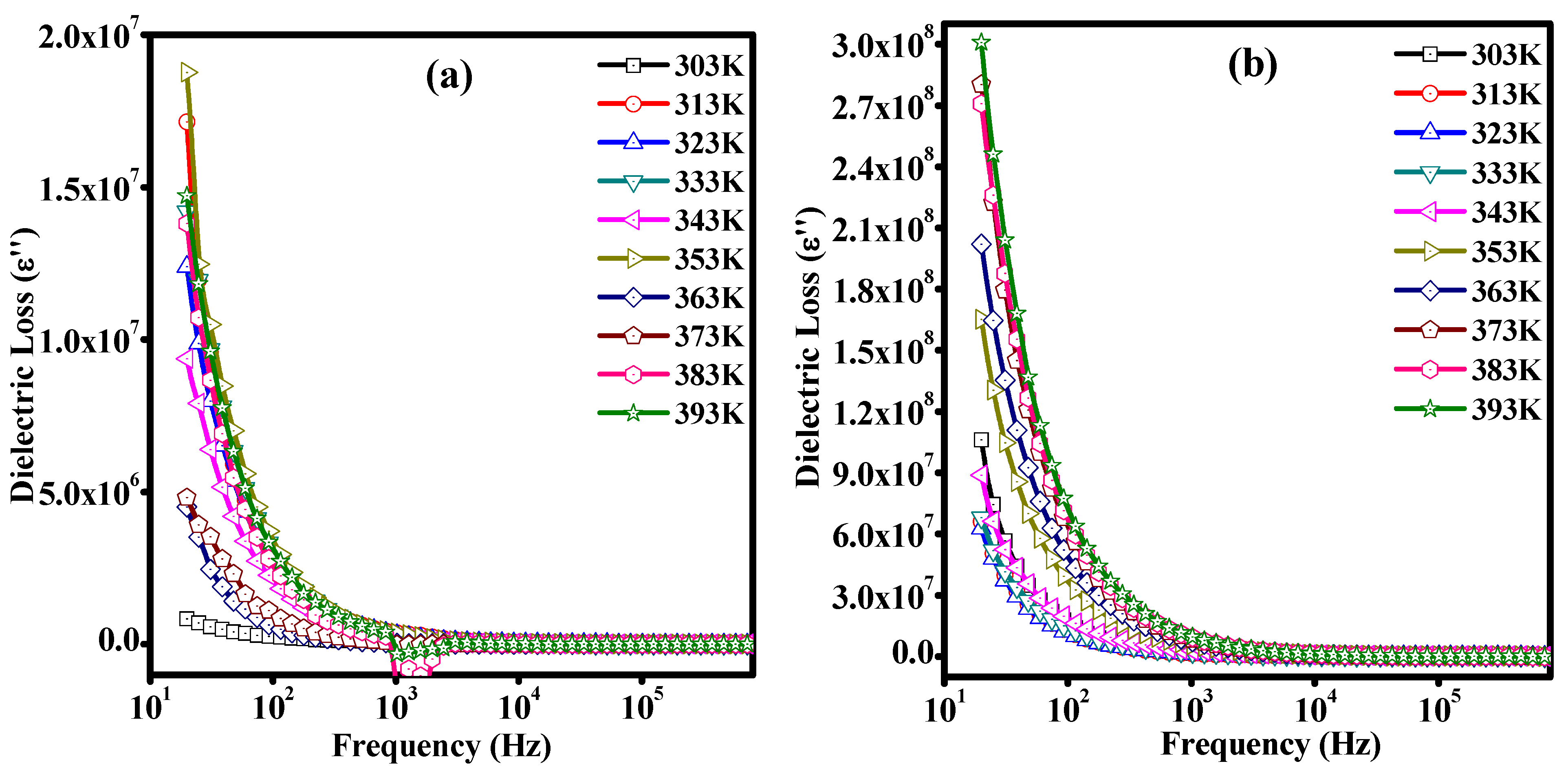
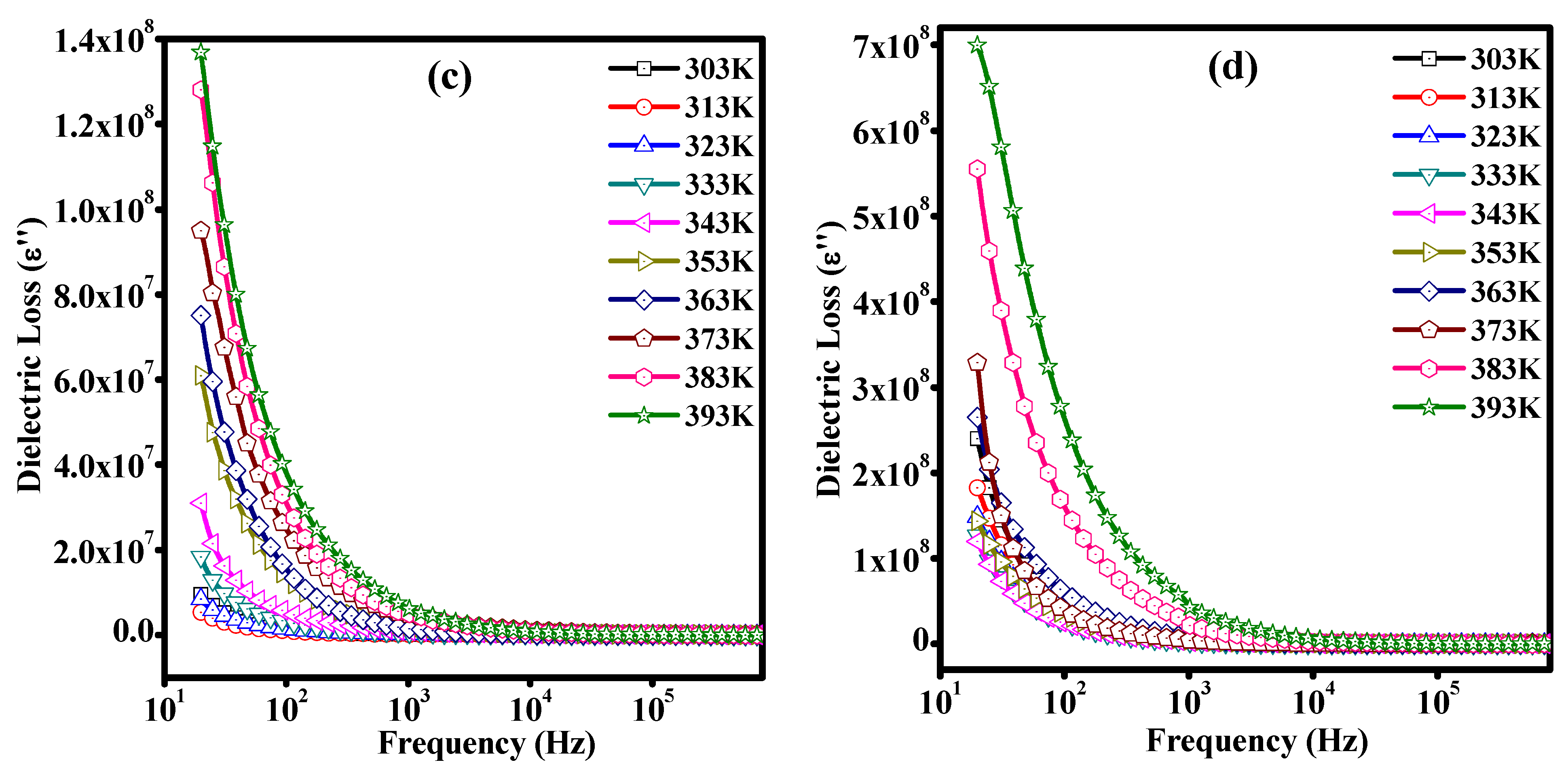
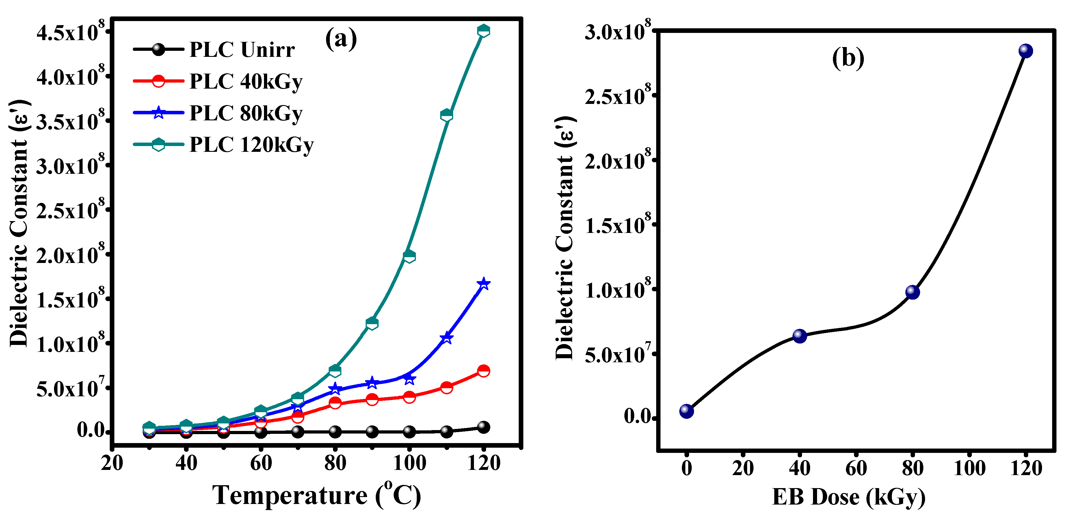
3.7. Dielectric Studies of Unirradiated and Irradiated PLC Nanocomposites

The dielectric property of a material is related to the dipole polarization with respect to the applied field. It is usually frequency dependent at lower frequencies and frequency independent at higher frequencies, which is due to the better orientation of the dipoles at the applied field at lower frequencies than at high frequencies [40]. The variations in the dielectric constant (ε′) and dielectric loss (ε″) of the unirradiated and EB-irradiated PLC nanocomposites at various temperatures, as well as the EB dose, as a function of frequencies, were studied and are presented in Figure 9 and Figure 10, respectively. The ε′ and ε″ parameters were calculated using the following equations:
ε = C p d / ( ε 0   A )
ε = ε tan δ
where d is the weight of the sample, A is the area of the electrode, and ε 0 is the dielectric permittivity in a vacuum (8.85 × 10⁻¹² Fm−1). From Figure 9 and Figure 10, it can be seen that ε′ and ε″ were completely frequency dependent at low frequencies of up to 1 kHz, and they decreased suddenly and then remained constant afterward. There was a gradual decrease in ε′ and ε″ for both the unirradiated and EB-irradiated PLC nanocomposites, with an increase in the frequency for all temperatures. This was due to the change in the direction of the dipole polarization with respect to the applied field and collection of charges between the sample (PLC nanocomposite pallet) and the electrode responsible for increasing ε′ and ε″ at lower frequencies. The ε′ and ε″ of the unirradiated and EB-irradiated PLC nanocomposites increased smoothly in the low-frequency range for all temperatures and EB irradiation doses of 40, 80, and 120 kGy (Figure 11a). This is attributed to an increase in the mobility of the dipoles. The dipoles are easily oriented with the direction of the applied field, and the dissociation of ion aggregates within the polymer matrix at high temperature, as well as EB energy, leads to an increase in the charge carrier density, resulting in an increase in the conductivity [41,42].
It can be noticed that ε′ and ε″ increased by more than one order of magnitude after irradiation with a 120 kGy EB dose (Figure 11b). This is due to the formation of defects and disorders in the band gap of the polymer matrix in the form of cross-links, chain scission processes, discontinuities, and bond breaks in the molecular chains that may produce a greater number of dipoles [35,43] and increase the delocalization of charge carriers in the polymer matrix. These results suggests that the irradiation process can modulate or improve the dielectric properties.

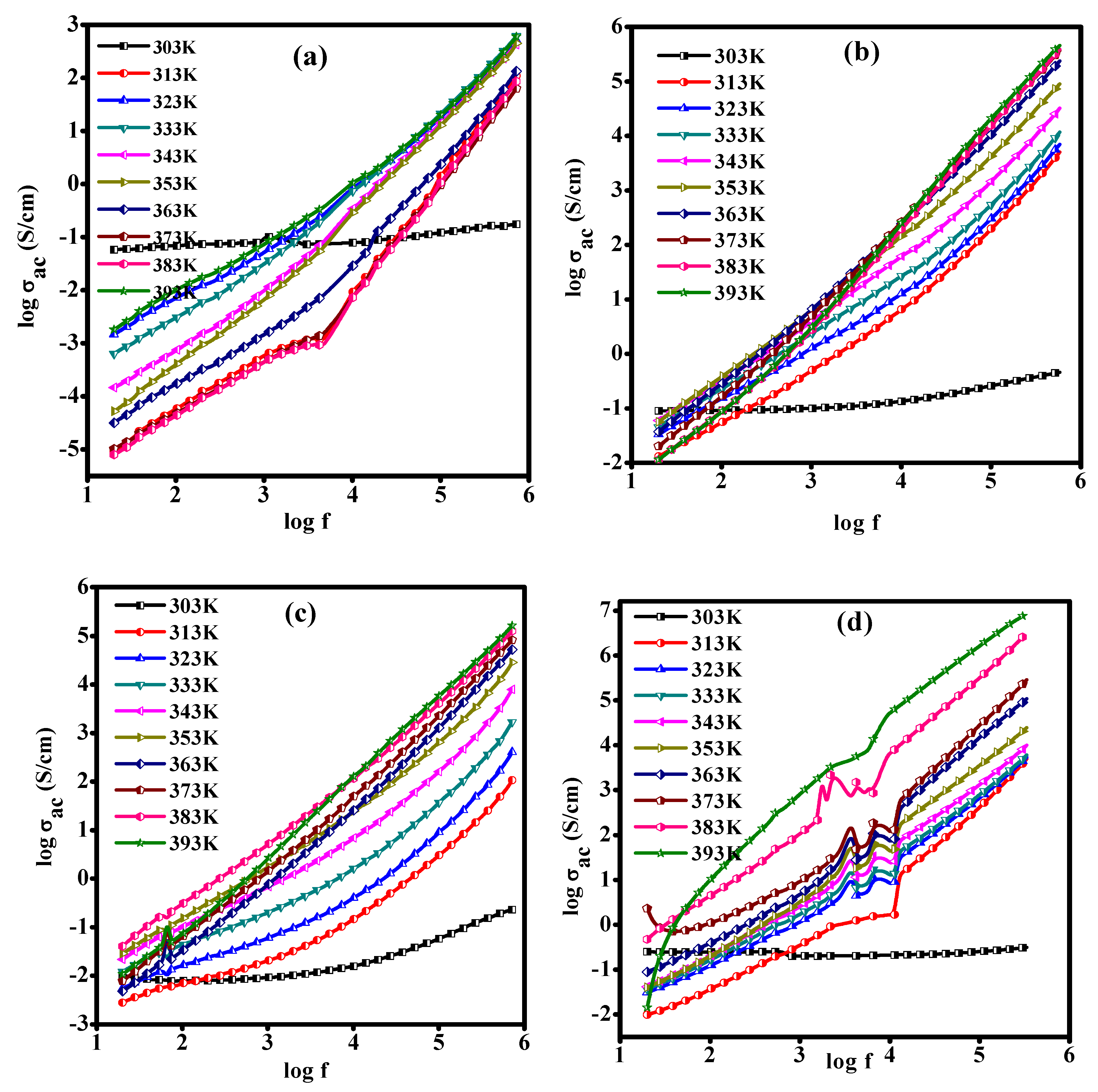
3.8. AC Conductivity of the PLC Nanocomposite

The frequency-dependent conductivity of the PLC nanocomposite with the influence of EB irradiation’s dose and temperature is shown in Figure 12. At low frequencies, as well as temperatures, the conductivity exhibited similar patterns; there was no maximum change at all doses. The total conductivity in the polymer matrix is the sum of the microscopic conductivity depending on the dopants and the macroscopic conductivity depending on the molecular orientations in the polymeric materials [44]. The increase in conductivity depends on the number of conduction paths established within the polymer nanocomposite. The width of the potential barriers decreased in the bulk regions as a result of the electrical path (i.e., network) developed in the polymer matrix. Consequently, the charge carriers are able to move freely via a hopping mechanism from one site to another, thereby increasing conductivity. The conductivity further increases with an increase in the EB irradiation dose, because the EB energy is able to change the polymer chemical bonding by the chain scission process in such a way that the polymer structure converts as hydrogen depleted carbon network and hence this network makes the polymer more conductive [45]. The ac conductivity (σac) was calculated by the equation,
σ ac = ω c p d   tan δ / A
where d is the thickness of the sample, A is the electrode area, ω is the angular frequency, and tan   δ is a loss tangent [46]. An increase in the ac conductivity with an increase in the EB dose was observed, which was mainly due to the release of trapped charges activated at higher frequencies. This is attributed to the formation of single- and/or double-helical bonds due to the large electronic energy loss along their trajectories by an inter-chain polymer cross-linking process, thus the number of free charge carriers increased in the polymer matrix after irradiation [4].

3.9. Temperature-Dependent Electrical Conductivity of the PLC Nanocomposite

The electrical conductivity was found to increase with an increase in the temperature, and this was confirmed by the Arrhenius plots (Figure 13a) and the increasing trend in the conductivity with the EB dose (Figure 13b). This is mainly due to the strong hopping mechanism and formation of the polaron/bipolarons at high temperatures, as well as the EB energy. The increase in the conductivity with the EB dose is attributed to the polymer chain’s degradation due to the EB’s effect on the interchain separation. This result is supported by the DSC, FTIR, XRD, and dielectric constant. Polymer chain degradation or segmentation occurs when the polymer undergoes a chain scission process, which lowers the molecular weight of the polymer matrix. This makes the distance between the polymer chains smaller, allowing the electrons to transfer more easily, which increases the charge carriers and, hence, the conductivity [4,47].
The electrical conductivity of KBr/PVA composite films increases with an increase in the electron beam irradiation dose. This is initially attributed to polymer chain cross-linking (below 150 kGy) and, subsequently, to chain scission (above 150 kGy) [48,49]. A study on a hybrid nanocomposite comprising a polymer matrix of polyaniline emeraldine-salt form (PANI-ES) reinforced with copper oxide II (CuO) particles, synthesized via in situ polymerization, revealed electrical conductivity values of 1.1 × 10⁻⁴ S/cm for PANI-ES and 2.77 × 10⁻⁴ S/cm for the PANI–CuO nanocomposite. The electrical conductivity of the nanocomposite was 60% greater than that of pure PANI-ES. This enhancement in the conductivity was attributed to the charge transfer, which improved the carrier mobility from PANI to the CuO slab. This observation indicates a significant interaction between the CuO (1 1 1) surface and PANI, causing the nanocomposite to exhibit metallic behavior. Additionally, the contribution of Cu and O orbitals augmented the density of the states of the nanocomposite, further elevating its electrical conductivity [50]. In the current study, the increased electron beam energy must be enhancing the abovementioned mechanisms. The rise in conductivity with the temperature represents thermally triggered behavior.

3.10. Cyclic Voltammetry of EB-Irradiated PLC Nanocomposite

The electrochemical performance of the PLC nanocomposite was examined using cyclic voltammetry in a 1 M KCl solution in the specially made three-electrode system at room temperature in the applied potential window of −4 to 4 V with a scan rate 300 mV/s, as illustrated in Figure 14a. The 120 kGy EB dose irradiated PLC nanocomposite at various scan rates of 0.1 V/s, 0.2 V/s, 0.3 V/s, 0.4 V/s, 0.5 V/s, and 0.6 V/s is shown in Figure 14b, with the scan direction indicated by arrows. The shapes of the CV curves are typically different from the rectangular shape due to the progress of the redox reaction, which indicates that the pseudocapacitive behavior of the sample leads to an increase in the charge mobility, hence revealing the energy storage characteristics of the PLC nanocomposite. As the irradiation dose increased, the integrated area under the CV curves increased significantly with an increase in the scan rate within the applied potential range. The shapes of the curves remained the same even at a high scan rate of about 600 mV/s, which is an indication of the capacitance behavior of the irradiated PLC nanocomposite. It was also observed that the current and voltage ranges of the PLC nanocomposite were enhanced after irradiation, which can be attributed to the fast ion transportation and, consequently, the high electrical conductivity [16,51]. The findings strongly indicate that the high-energy electron-beam-irradiated PLC nanocomposite is a viable material for supercapacitor applications and serves effectively as an electrode material for electrochemical applications.

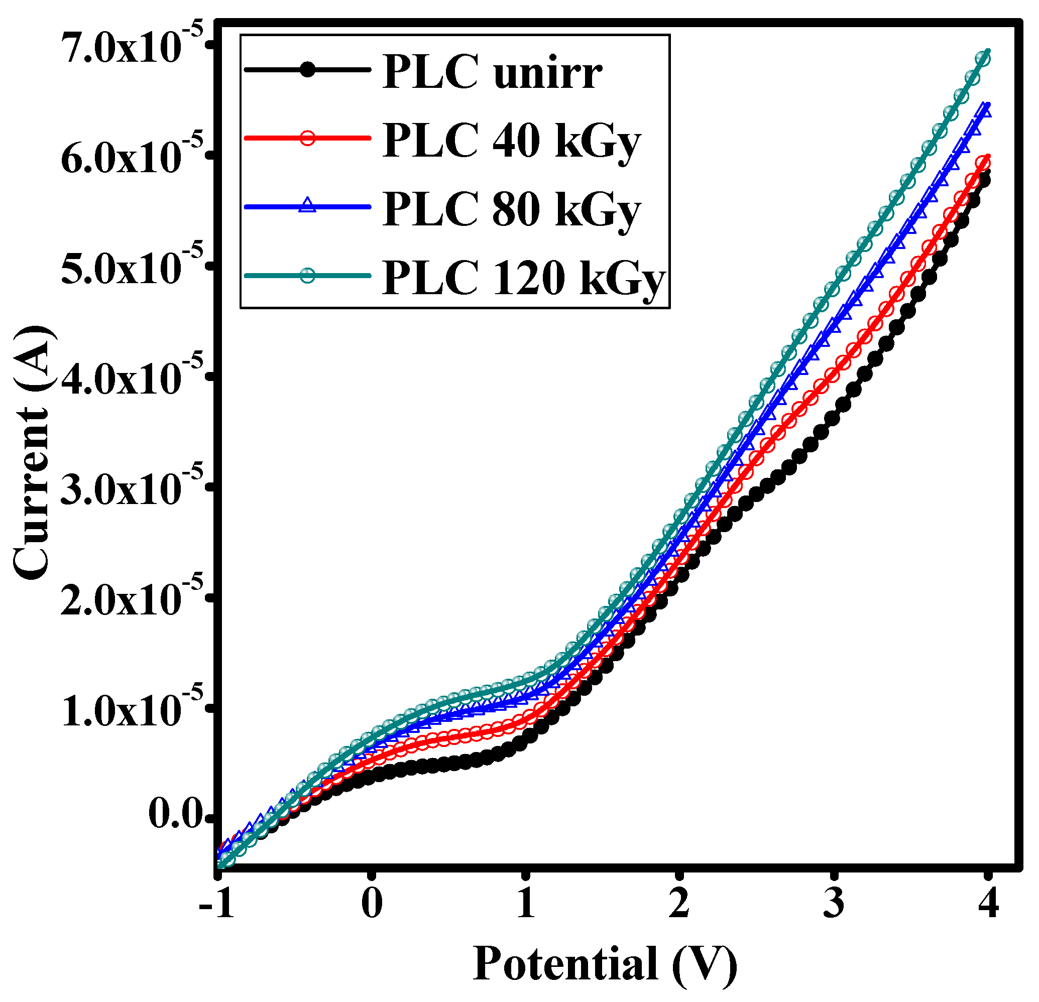
3.11. I-V Characteristic Studies

The current as a function of the voltage was measured for the PLC nanocomposite before and after EB irradiation, as shown in Figure 15. The conducting behavior of a semiconducting polymer PANI nanocomposite is due to the presence of conjugational defects like polarons and bipolarons in the molecular chain and the electrons and trapped ions in the polymer matrix. An increase in the current was observed with an increase in the EB energy, which may be due the creation of energy levels within the energy gaps; hence, the energy band gap decreased (i.e., introduced new energy levels within the existing gap). The I-V characteristics plot of the PLC nanocomposite before and after irradiation exhibited a nonohmic nature. This nonlinear increase in the current with the applied potential is mainly due to the charge transport involved in the formation of polarons and bipolarons upon irradiation. Initially, there was a low current for up to 1 V of the applied voltage for all doses. After the applied voltage increased to 4 V, the current increased drastically along with the EB dose, confirming an increase in the formation of polarons/bipolarons. Hence, they contribute to the high current via the charge transfer mechanism in the system, acting as charge carrier defect states, which are important in PANI-based composites [52].
The dc conductivity (σdc) values of the PLC nanocomposite before and after EB irradiation for various doses were calculated using the I-V curve with the help of the following equation [53]:
σ d c = I t V A
where I(A) is the current, t is the thickness of the sample, A is the cross-sectional area of the sample, and V is the voltage. The calculated conductivity values were found to gradually increase with the increase in the EB doses (0 to 120 kGy), namely, 8.77 × 10⁻⁵ S/cm, 9.07 × 10⁻⁵ S/cm, 9.67 × 10⁻⁵ S/cm, and 1.05 × 10⁻⁴ S/cm for the PLCs Unirr and the 40, 80, and 120 kGy EB doses, respectively. These values are greater than those reported for γ-ray-irradiated polyaniline-based composites [54]. The results demonstrate an increase in the dc conductivity of the electron-beam-irradiated samples relative to the unirradiated samples.
In Table 3, radiation type, conductivity and energy band gap in the current study and those previously documented from other sources are compared.
The PANI/LiClO4/CuO nanocomposite demonstrates promising characteristics for various applications, particularly when compared to the values in the table above. The conductivity and energy band gap of this composite are expected to maintain a balance between the electrical conductivity and optical properties, which is essential for sensors, energy storage devices, and electronic components.
PANI-based composites, such as PANI/LiClO4/CuO, typically show an improved conductivity due to the ionic conductivity of LiClO4, which enhances the charge transport properties. This makes it potentially more efficient than composites like NiO/PANI (with conductivity values of around 10−3 S/cm) or CuO/PANI composites (with conductivities in the range of 10−3 to 10−2 S/cm), as shown in the Table 3. The presence of CuO (copper oxide) in the composite further boosts conductivity, especially in electrochemical applications.
Energy band gaps for such composites generally lie between 2.8 eV and 3.4 eV, which is in line with the table’s values, making them suitable for optoelectronic applications. These properties are significant in devices where both conductivity and stability are crucial, such as in batteries, supercapacitors, and electrochemical sensors.
Overall, the PANI/LiClO4/CuO nanocomposite is likely to exhibit improved stability and performance compared to many other PANI-based composites, making it a good candidate for energy storage, flexible electronics, and sensor technologies.

4. Conclusions

The chemically synthesized PLC PANI/LiClO4/CuO nanocomposite was subjected to electron beam energy at doses of 40, 80, and 120 kGy, and the alterations in the characteristics were compared with those of the unirradiated sample. The FTIR analysis confirmed the effect of EB on the molecular structure through cross-linking processes and chain scission, resulting in the breaking of chemical bonds and morphological changes, especially at a higher level of EB energy. Reductions in the crystallinity of the sample were detected via XRD and DSC analyses, and the emergence of more amorphous regions promoted the easy movement of ions. The irradiation process may improve the optical properties of the PLC nanocomposites, based on the optical absorption and band gap analyses. Pronounced reductions in the band gaps (Eg), from 2.15 to 1.84, 1.81, and 1.77 eV, were noted after the 40, 80, and 180 Gky beam irradiation. Thermal analysis verified the improved thermal stability after irradiation. In the PLC nanocomposites, the dielectric characteristics, electrochemical stability, and electrical conductivity were all impacted by the EB irradiation and may be altered or enhanced by adjusting the input EB dose. The findings indicate that following irradiation with EB energy, the PLC nanocomposite material can be utilized in high-temperature devices, storage systems, and rechargeable batteries because of its high thermal and high storage properties.

Author Contributions

Conceptualization, Y.L. and S.C.; Methodology, Y.L.; Software, Y.L.; Validation, Y.L., S.C. and N.N.; Formal analysis, Y.L. and S.C.; Investigation, Y.L. and S.C.; Resources, S.C.; Data curation, Y.L.; Writing—original draft preparation, Y.L. and S.C.; Writing—review and editing, S.C. and N.N.; Visualization, S.C. and N.N.; Supervision, S.C.; Project administration, S.C. All authors have read and agreed to the published version of the manuscript.

Funding

This research was funded by Faculty Research Promotion Scheme (FRPS) vide Project No. R&D/FRPS/2023-24/PHY/01.

Institutional Review Board Statement

Not applicable.

Informed Consent Statement

Not applicable.

Data Availability Statement

The original contributions presented in this study are included in the article. Further inquiries can be directed to the corresponding author.

Conflicts of Interest

The authors declare no conflicts of interest.

References

  1. Drobny, J.G. Radiation Technology for Polymers; CRC Press: Boca Raton, FL, USA, 2021. [Google Scholar]
  2. Fifield, L.S.; Pharr, M.; Staack, D.; Pillai, S.D.; Nichols, L.; McCoy, J.; Faucette, T.; Bisel, T.T.; Huang, M.; Hasan, M.K. Direct comparison of gamma, electron beam and X-ray irradiation effects on single-use blood collection devices with plastic components. Radiat. Phys. Chem. 2021, 180, 109282. [Google Scholar] [CrossRef]
  3. Czvikovszky, T. Reactive recycling of multiphase polymer systems through electron beam. Nucl. Instrum. Methods Phys. Res. Sect. B Beam Interact. Mater. At. 1995, 105, 233–237. [Google Scholar] [CrossRef]
  4. Raghu, S.; Kilarkaje, S.; Sanjeev, G.; Nagaraja, G.; Devendrappa, H. Effect of electron beam irradiation on polymer electrolytes: Change in morphology, crystallinity, dielectric constant and AC conductivity with dose. Radiat. Phys. Chem. 2014, 98, 124–131. [Google Scholar] [CrossRef]
  5. Hong, Y.K.; Park, D.H.; Park, S.H.; Park, S.K.; Joo, J. Effects of electron-beam irradiation on conducting polypyrrole nanowires. Appl. Phys. Lett. 2009, 94, 053111. [Google Scholar] [CrossRef]
  6. Heeger, A.J. Semiconducting and metallic polymers: The fourth generation of polymeric materials. J. Phys. Chem. B 2001, 105, 8475–8491. [Google Scholar] [CrossRef]
  7. MacDiarmid, A.G. “Synthetic metals”: A novel role for organic polymers. Curr. Appl. Phys. 2001, 1, 269–279. [Google Scholar] [CrossRef]
  8. Rayar, A.; Chapi, S.; Murugendrappa, M.G.; Babaladimath, G.; Harish, K.; Kakarla, R.R.; Raghu, A.V. Organic conjugated polymers and their nanostructured composites: Synthesis methodologies and electrochemical applications. Nano-Struct. Nano-Objects 2024, 37, 101102. [Google Scholar] [CrossRef]
  9. Nandihalli, N.; Liu, C.-J.; Mori, T. Polymer based thermoelectric nanocomposite materials and devices: Fabrication and characteristics. Nano Energy 2020, 78, 105186. [Google Scholar] [CrossRef]
  10. Kuznetsova, L.S.; Arlyapov, V.A.; Plekhanova, Y.V.; Tarasov, S.E.; Kharkova, A.S.; Saverina, E.A.; Reshetilov, A.N. Conductive polymers and their nanocomposites: Application features in biosensors and biofuel cells. Polymers 2023, 15, 3783. [Google Scholar] [CrossRef]
  11. Bhattacharyya, A. Conducting Polymers in Biosensing: A review. Chem. Phys. Impact 2024, 8, 100642. [Google Scholar] [CrossRef]
  12. Sood, Y.; Singh, K.; Mudila, H.; Lokhande, P.; Singh, L.; Kumar, D.; Kumar, A.; Mubarak, N.M.; Dehghani, M.H. Insights into properties, synthesis and emerging applications of polypyrrole-based composites, and future prospective: A review. Heliyon 2024, 10, e33643. [Google Scholar] [CrossRef] [PubMed]
  13. Clough, R. High-energy radiation and polymers: A review of commercial processes and emerging applications. Nucl. Instrum. Methods Phys. Res. Sect. B Beam Interact. Mater. At. 2001, 185, 8–33. [Google Scholar]
  14. Sabharwal, S. Electron beam irradiation applications. In Proceedings of the 25th North American Particle Accelerator Conference, Pasadena, CA, USA, 29 September–4 October 2013; pp. 745–748. [Google Scholar]
  15. Permana, A.A.; Chirasatitsin, S.; Putson, C. Electron-beam irradiation for boosting storage energy density of tuned poly (vinylidene fluoride-hexafluoropropylene)/graphene nanoplatelet polymer composites. Crystals 2020, 10, 633. [Google Scholar] [CrossRef]
  16. Yesappa, L.; Niranjana, M.; Ashokkumar, S.; Vijeth, H.; Raghu, S.; Devendrappa, H. Characterization, electrical conductivity and electrochemical performance of polyaniline-LiClO4-CuO nano composite for energy storage applications. Polym.-Plast. Technol. Mater. 2019, 58, 193–205. [Google Scholar]
  17. Yesappa, L.; Niranjana, M.; Ashokkumar, S.; Vijeth, H.; Sharanappa, C.; Raghu, S.; Devendrappa, H. Investigation of the structure, optical and electrical properties of lithium perchlorate doped polyaniline composite: Aloe vera used as a bio-plasticizer. J. Electron. Mater. 2017, 46, 6965–6976. [Google Scholar] [CrossRef]
  18. Dhanabalan, A.; Malmonge, J.A.; Riul Jr, A.; Faria, R.M.; Oliveira Jr, O. A study on X-ray irradiation of composite polyaniline LB films. Thin Solid Film. 1998, 327, 808–812. [Google Scholar] [CrossRef]
  19. Bodugoz, H.; Sevil, U.; Güven, O. Radiation-induced conductance in the blends of poly (aniline-base) with poly (vinyl chloride) and poly [(vinylidene chloride)-co-(vinyl acetate)]. Macromol. Symp. 2001, 169, 289–295. [Google Scholar]
  20. Sevil, U.; Güven, O.; Kovacs, A.; Slezsak, I. Gamma and electron dose response of the electrical conductivity of polyaniline based polymer composites. Radiat. Phys. Chem. 2003, 67, 575–580. [Google Scholar] [CrossRef]
  21. Bhadra, S.; Khastgir, D. Degradation and stability of polyaniline on exposure to electron beam irradiation (structure–property relationship). Polym. Degrad. Stab. 2007, 92, 1824–1832. [Google Scholar]
  22. Güven, O. Radiation-induced conductivity control in polyaniline blends/composites. Radiat. Phys. Chem. 2007, 76, 1302–1307. [Google Scholar]
  23. Relekar, B.; Fulari, A.; Rath, M.; Fulari, V.; Lohar, G. Modification in porous MnO2/PANI composite using high-energy electron irradiation for electrochemical supercapacitor. J. Mater. Sci. Mater. Electron. 2020, 31, 11741–11747. [Google Scholar]
  24. Vallée, A.; Besner, S.; Prud’Homme, J. Comparative study of poly (ethylene oxide) electrolytes made with LiN(CF3SO2)2, LiCF3SO3 and LiClO4: Thermal properties and conductivity behaviour. Electrochim. Acta 1992, 37, 1579–1583. [Google Scholar]
  25. Atchaya, S.; Meena Devi, J. Experimental Investigation on Structural, Optical, Electrical and Magnetic Properties of Copper Oxide Nanoparticles. Proc. Natl. Acad. Sci. India Sect. A Phys. Sci. 2024, 94, 153–160. [Google Scholar]
  26. Ates, M.; Serin, M.A.; Ekmen, I.; Ertas, Y.N. Supercapacitor behaviors of polyaniline/CuO, polypyrrole/CuO and PEDOT/CuO nanocomposites. Polym. Bull. 2015, 72, 2573–2589. [Google Scholar]
  27. Patil, P.G.; Langade, K.J.; Vyawahare, S.K. Development of the PANI-CuO and PANI-CuO-GO Nanocomposite Architecture and Comparative Investigation of the Physicochemical, Optical and Electrochemical Properties Towards Supercapacitor Applications. J. Inorg. Organomet. Polym. Mater. 2024, 1–12. [Google Scholar] [CrossRef]
  28. Ramaprasad, A.; Rao, V.; Sanjeev, G. Synthesis of chitin-polyaniline nanocomposite by electron beam irradiation. J. Appl. Polym. Sci. 2011, 121, 623–633. [Google Scholar] [CrossRef]
  29. Zeghioud, H.; Lamouri, S.; Mahmoud, Y.; Hadj-Ali, T. Preparation and characterization of a new polyaniline salt with good conductivity and great solubility in dimethyl sulfoxyde. J. Serbian Chem. Soc. 2015, 80, 1435–1448. [Google Scholar]
  30. Chapi, S.; Murugendrappa, M.; Rayar, A.; Babaladimath, G.; Raghavendra, N.; Yazdi, M.K.; Ryl, J.; Saeb, M.R. Enhanced structural, electrical, and electrochemical performance of polyethylene oxides (PEO)-based polymer electrolytes for solid state K+ ion batteries. J. Appl. Polym. Sci. 2024, 141, e55390. [Google Scholar]
  31. Butoi, B.; Groza, A.; Dinca, P.; Balan, A.; Barna, V. Morphological and structural analysis of polyaniline and poly (o-anisidine) layers generated in a DC glow discharge plasma by using an oblique angle electrode deposition configuration. Polymers 2017, 9, 732. [Google Scholar] [CrossRef]
  32. Du, X.; Xu, Y.; Xiong, L.; Bai, Y.; Zhu, J.; Mao, S. Polyaniline with high crystallinity degree: Synthesis, structure, and electrochemical properties. J. Appl. Polym. Sci. 2014, 131, 40827. [Google Scholar]
  33. Gul, S.; Bilal, S. Synthesis and characterization of processable polyaniline salts. J. Phys. Conf. Ser. 2013, 439, 012002. [Google Scholar] [CrossRef]
  34. Wang, S.; Tan, Z.; Li, Y.; Sun, L.; Zhang, T. Synthesis, characterization and thermal analysis of polyaniline/ZrO2 composites. Thermochim. Acta 2006, 441, 191–194. [Google Scholar]
  35. Raghu, S.; Archana, K.; Sharanappa, C.; Ganesh, S.; Devendrappa, H. The physical and chemical properties of gamma ray irradiated polymer electrolyte films. J. Non-Cryst. Solids 2015, 426, 55–62. [Google Scholar]
  36. Singh, D.; Singh, N.; Qureshi, A.; Kulriya, P.; Tripathi, A.; Avasthi, D.; Gulluoglu, A.N. Radiation induced modification of dielectric and structural properties of Cu/PMMA polymer composites. J. Non-Cryst. Solids 2010, 356, 856–863. [Google Scholar] [CrossRef]
  37. Wang, B.; Gao, X.; Piao, G. Preparation of Polyaniline-Doped Fullerene Whiskers. Int. J. Polym. Sci. 2013, 2013, 867934. [Google Scholar] [CrossRef]
  38. Sonkawade, R.; Kumar, V.; Annapoorni, S.; Vaijapurkar, S.; Dhaliwal, A. Effects of gamma ray and neutron radiation on polyanilne conducting polymer. Indian J. Pure Appl. Phys. 2010, 48, 453–456. [Google Scholar]
  39. Mohd Meftah, A.; Gharibshahi, E.; Soltani, N.; Mat Yunus, W.M.; Saion, E. Structural, optical and electrical properties of PVA/PANI/Nickel nanocomposites synthesized by gamma radiolytic method. Polymers 2014, 6, 2435–2450. [Google Scholar] [CrossRef]
  40. Yesappa, L.; Niranjana, M.; Ashokkumar, S.; Vijeth, H.; Basappa, M.; Dwivedi, J.; Petwal, V.; Ganesh, S.; Devendrappa, H. Optical properties and ionic conductivity studies of an 8 MeV electron beam irradiated poly (vinylidene fluoride-co-hexafluoropropylene)/LiClO 4 electrolyte film for opto-electronic applications. RSC Adv. 2018, 8, 15297–15309. [Google Scholar]
  41. Jali, V.; Aparna, S.; Sanjeev, G.; Krupanidhi, S. ac conductivity studies on the electron irradiated BaZrO3 ceramic. Nucl. Instrum. Methods Phys. Res. Sect. B Beam Interact. Mater. At. 2007, 257, 505–509. [Google Scholar]
  42. Hanafy, T.A. Dielectric relaxation and Schottky conduction of IR laser irradiated Makrofol-DE polycarbonate. J. Appl. Polym. Sci. 2012, 124, 1–8. [Google Scholar]
  43. Raghu, S.; Archana, K.; Sharanappa, C.; Ganesh, S.; Devendrappa, H. Electron beam and gamma ray irradiated polymer electrolyte films: Dielectric properties. J. Radiat. Res. Appl. Sci. 2016, 9, 117–124. [Google Scholar]
  44. Vishnuvardhan, T.; Kulkarni, V.; Basavaraja, C.; Raghavendra, S. Synthesis, characterization and ac conductivity of polypyrrole/Y2O3 composites. Bull. Mater. Sci. 2006, 29, 77–83. [Google Scholar] [CrossRef]
  45. Shah, S.; Singh, N.; Qureshi, A.; Singh, D.; Singh, K.; Shrinet, V.; Tripathi, A. Dielectric and structural modification of proton beam irradiated polymer composite. Nucl. Instrum. Methods Phys. Res. Sect. B Beam Interact. Mater. At. 2008, 266, 1768–1774. [Google Scholar]
  46. Nandihalli, N.; Gregory, D.H.; Mori, T. Energy-saving pathways for thermoelectric nanomaterial synthesis: Hydrothermal/solvothermal, microwave-assisted, solution-based, and powder processing. Adv. Sci. 2022, 9, 2106052. [Google Scholar]
  47. Tiptipakorn, S.; Suwanmala, P.; Hemvichian, K.; Pornputtanakul, Y. Effects of electron beam on irradiated polyimide/polyaniline composites. Adv. Mater. Res. 2012, 550, 861–864. [Google Scholar]
  48. Mahantesha, B.; Ravindrachary, V.; Padmakumari, R.; Sahanakumari, R.; Tegginamata, P.; Sanjeev, G.; Petwal, V.; Verma, V. Effect of electron irradiation on optical, thermal and electrical properties of polymer electrolyte. J. Radioanal. Nucl. Chem. 2019, 322, 19–27. [Google Scholar]
  49. Nanda, P.; Maity, S.; Pandey, N.; Ray, R.; Thakur, A.; Tarafdar, S. Conductivity enhancement in polymer electrolytes on gamma irradiation. Radiat. Phys. Chem. 2011, 80, 22–27. [Google Scholar]
  50. de Souza, V.S.; da Frota, H.O.; Sanches, E.A. Polyaniline-CuO hybrid nanocomposite with enhanced electrical conductivity. J. Mol. Struct. 2018, 1153, 20–27. [Google Scholar]
  51. Kim, J.; Ju, H.; Inamdar, A.I.; Jo, Y.; Han, J.; Kim, H.; Im, H. Synthesis and enhanced electrochemical supercapacitor properties of Ag–MnO2–polyaniline nanocomposite electrodes. Energy 2014, 70, 473–477. [Google Scholar]
  52. Bhowmik, K.L.; Deb, K.; Bera, A.; Nath, R.K.; Saha, B. Charge transport through polyaniline incorporated electrically conducting functional paper. J. Phys. Chem. C 2016, 120, 5855–5860. [Google Scholar]
  53. Vijeth, H.; Ashokkumar, S.; Yesappa, L.; Niranjana, M.; Vandana, M.; Devendrappa, H. Flexible and high energy density solid-state asymmetric supercapacitor based on polythiophene nanocomposites and charcoal. RSC Adv. 2018, 8, 31414–31426. [Google Scholar]
  54. Bhat, N.V.; Nate, M.M.; Gore, A.V.; Bhat, R.M. Interaction of gamma radiation with PVA/PANi composite films: Structural and morphological studies. J. Appl. Polym. Sci. 2008, 110, 2243–2252. [Google Scholar] [CrossRef]
  55. Benykhlef, S.; Bekhoukh, A.; Berenguer, R.; Benyoucef, A.; Morallon, E. PANI-derived polymer/Al2O3 nanocomposites: Synthesis, characterization, and electrochemical studies. Colloid Polym. Sci. 2016, 294, 1877–1885. [Google Scholar] [CrossRef]
  56. Raghu, S.; Devendrappa, H.; Ganesh, S.; Matteppanavar, S. Modification of PEO-based polymer electrolytes by electron beam irradiation for energy storage applications. Polym. Bull. 2023, 80, 381–394. [Google Scholar] [CrossRef]
  57. Chapi, S. Optical, electrical and electrochemical properties of PCL5/ITO transparent conductive films deposited by spin-coating—Materials for single-layer devices. J. Sci. Adv. Mater. Devices 2020, 5, 322–329. [Google Scholar] [CrossRef]
  58. Kolhar, P.; Sannakki, B.; Verma, M.; Suresha, S.; Alshehri, M.; Shah, N.A. Investigation of structural, dielectric and optical properties of polyaniline—Magnesium ferrite composites. Nanomaterials 2023, 13, 2234. [Google Scholar] [CrossRef]
  59. Devendrappa, H.; Yesappa, L.; Niranjana, M.; Ashokkumar, S.; Vijeth, H.; Ganesh, S. Morphology, optical and ionic conductivity studies of electron beam irradiated polymer electrolyte film. AIP Conf. Proc. 2018, 1942, 110003. [Google Scholar]
Scheme 1. Systematic depiction of the PLC nanocomposite synthesis and representative EB irradiation effect.
Applsci 15 04001 sch001
Figure 1. FTIR spectra of the PLC nanocomposite at varying dosages before and after EB irradiation.
Applsci 15 04001 g001
Figure 2. FESEM images of the PLC nanocomposites: (a) PLC unirradiated; (b) PLC 40 kGy; (c) PLC 80 kGy; (d) PLC 120 kGy EB irradiation doses.
Applsci 15 04001 g002
Figure 3. EDX spectra of the PLC nanocomposite: (a) PLC unirradiated; (b) PLC 40 kGy; (c) PLC 80 kGy; (d) PLC 120 kGy EB irradiation doses.
Applsci 15 04001 g003
Figure 4. XRD patterns of the unirradiated and 120 kGy dose EB-irradiated sample.
Applsci 15 04001 g004
Figure 5. (a) TGA and (b) DTA curves of Unirr and EB-irradiated PLC nanocomposites.
Applsci 15 04001 g005
Figure 6. DSC Curves of the unirr and EB-irradiated PLC nanocomposites.
Applsci 15 04001 g006
Figure 7. UV-Visible spectra of the PLC nanocomposites and EB irradiated at 40 kGy, 80 kGy, and 120 kGy doses.
Applsci 15 04001 g007
Figure 8. The (αhν)2 vs. photon energy (hν) plots for the PLC nanocomposites before and after EB irradiation with various doses.
Applsci 15 04001 g008
Figure 9. Dielectric constant (ε′) variation with the frequency at various temperatures in the unirradiated (a) and EB-irradiated (b) PLC40 kGy, (c) PLC80 kGy, and (d) PLC120 kGy nanocomposites.
Applsci 15 04001 g009
Figure 10. Variation in the dielectric loss (ε″) with the frequency at various temperatures in the unirradiated (a) and EB-irradiated PLC nanocomposites, (b) PLC40 kGy, (c) PLC80 kGy, and (d) PLC120 kGy.
Applsci 15 04001 g010aApplsci 15 04001 g010b
Figure 11. Variation in the dielectric constant (ε′) with (a) temperature and (b) EB irradiation doses.
Applsci 15 04001 g011
Figure 12. Log conductivity vs. log frequency for the PLC nanocomposite: (a) unirradiated; (b) 40 kGy, (c) 80 kGy, and (d) 120 kGy EB doses.
Applsci 15 04001 g012
Figure 13. (a) Arrhenius behavior plots with the reciprocal temperature; (b) variation in the conductivity against the EB dose at low (303 K) and high (393 K) temperatures.
Applsci 15 04001 g013
Figure 14. (a) CV plots for the PLC nanocomposite before and after EB irradiation and (b) cyclic voltammetry plots for the 120 kGy EB irradiated PLC nanocomposite at 0.1 V/s, 0.2 V/s, 0.3 V/s, 0.4 V/s, 0.5 V/s, and 0.6 V/s scan rates.
Applsci 15 04001 g014
Figure 15. I-V characteristic plots before and after the EB irradiation of the PLC nanocomposite at room temperature.
Applsci 15 04001 g015
Table 1. EDX parameters of the PLC nanocomposite with various dosages before and after EB irradiation.
ElementPLC UnirrPLC 40 kGyPLC 80 kGyPLC 120 kGy
Weight %Atom %Weight %Atom %Weight %Atom %Weight %Atom %
N0.0523.890.5724.520.4123.231.0125.35
O--1.0037.550.6732.981.8340.26
S0.024.580.112.070.102.460.181.99
Cl0.1122.000.8113.680.8919.880.999.81
C0.0317.980.4422.190.3321.460.7722.58
Table 2. Percentages of crystallinity (% χ), d (Å), strain (ɛ), full-width half maxima (β), size of the crystallite D (Å), separation between crystallites R (Å), and estimated XRD data.
Sample2θdΒɛRD% χ
PLC-Unirr25.063.5504.81851.1712.100.2379.55
20.254.3795.66621.347.350.2476.49
15.075.8715.66621.405.480.2573.76
9.149.6663.09890.774.440.4459.19
PLC-120 kGy25.103.5447.78731.9011.270.1859.23
19.994.4366.99251.726.960.2056.83
15.905.5676.99251.735.550.2148.77
9.819.0065.82671.454.440.2332.76
Table 3. Comparison of the nature of irradiation employed, conductivity and energy band gap in the present work with those previously reported elsewhere.
Sl. No.Name of the SampleDose Type (Irradiation)Conductivity (S/cm)Energy Band Gap (eV)Ref.
1.PANI-derived polymer/Al2O3 nanocompositesUnirr9.2 × 10−2-[55]
2.PEO-based polymer electrolytesElectron beam 3.4 × 10⁻⁴-[56]
3IT5 (PCL5/ITO/glass)Unirr.1.21 × 10−33.47[57]
4MgFe2O4 CompositesUnirr.-2.52[58]
5PEO:Li2SO4 polymer electrolyte Electron beam1.88 × 10−4-[4]
6PEO: CdCl2 (75:25%)Electron beam1.74 × 10−4-[43]
7PVdF-co-HFP: LiClO4 = 90:10Electron beam8.28 × 10−42.65[59]
8PEO-CdCl2 polymer electrolyteGamma ray1.15 × 10−43.80[35]
9PANI/LiClO4/CuO nanocompositeUnirr8.77 × 10–52.15Present work
10PANI/LiClO4/CuO nanocompositeElectron Beam 1.05 × 10−41.77Present work
Disclaimer/Publisher’s Note: The statements, opinions and data contained in all publications are solely those of the individual author(s) and contributor(s) and not of MDPI and/or the editor(s). MDPI and/or the editor(s) disclaim responsibility for any injury to people or property resulting from any ideas, methods, instructions or products referred to in the content.

