1. Introduction
Modern advanced ship propulsion systems have put forward more stringent requirements for acoustic stealth [
1]. In the process of ship propulsion, the thrust bearing is a crucial component for transmitting propulsive force to the hull, and its vibrations can lead to resonance throughout the entire hull structure. Consequently, there has been a significant increase in the development of vibration-damping thrust bearings, both domestically and internationally. Currently, the primary methods for reducing vibration and noise include rubber vibration damping [
2], hydraulic vibration damping [
3], and polymer material vibration damping [
4], among others. These techniques have achieved some success, particularly in minimizing vibrations in the middle and high-frequency ranges. However, the effectiveness of vibration damping in the middle and low-frequency bands has not yet met expectations. As a result, there is an urgent need to explore new technologies to enhance the acoustic stealth of thrust bearings, particularly in improving vibration and noise reduction capabilities in the middle and low-frequency ranges.
Permanent magnet thrust bearings offer a natural advantage in vibration and noise reduction. They utilize the magnetic force generated by permanent magnets to achieve contactless levitation of the rotor, enabling the rotor and stator to remain mutually separated without the need for lubrication or friction during operation. This unique feature makes permanent magnet thrust bearings especially suitable for use in contactless transmission systems, such as spacecraft [
5], flywheel energy storage systems [
6], and high-precision machine tools [
7]. Due to their contactless operation, permanent magnet thrust bearings provide key advantages, including frictionless motion, low noise, and high-speed capabilities.
Given the excellent performance of permanent magnet bearings, many researchers have focused on various aspects, such as bearing structure design, bearing capacity, stiffness, optimization, and experimental methods. In flywheel energy storage systems, permanent magnet bearings have shown promising application prospects and have attracted considerable attention. One study [
8] proposed a numerical method for the structural design of a new type of permanent magnet bearing for flywheel energy storage systems, enabling rapid determination of the bearing’s force, stiffness, and damping characteristics, which was experimentally validated. Another study [
6] introduced a system utilizing both superconducting magnetic bearings and permanent magnet bearings, where superconducting magnetic bearings suppress the vibration of the flywheel rotor while permanent magnet bearings passively control the rotor’s position, demonstrating excellent control effectiveness.
To improve the bearing capacity of permanent magnet bearings, another approach [
9] combined permanent magnet bearings with fluid bearing technology. This approach explores the possibility of achieving both low starting torque in permanent magnet bearings and high bearing capacity in fluid bearings under a single-bearing arrangement. Experimental results have shown an improvement in bearing capacity. In centrifuge rotating bearings, which are subjected to extreme working conditions such as high rotational speeds, traditional contact bearings are prone to metal fatigue, cracks, and other failures that compromise their operational lifespan. To address this, one study [
10] proposed a centrifuge-specific permanent magnetic bearing, leveraging the non-contact nature of permanent magnetic bearings to achieve high rotational speeds and extend bearing life.
The bearing capacity and stiffness of permanent magnet bearings are crucial mechanical characteristics. To investigate how structural parameters—such as thickness, width, number of layers, cross-sectional area, and air gap—affect the mechanical properties of radially magnetized permanent magnet bearings, researchers [
11] conducted in-depth studies, providing valuable insights into structural design. To address the challenges associated with the complex structure, intricate design, and difficult processing and assembly of permanent magnet bearings, another paper [
12] proposed a modular permanent magnet bearing. This work introduced the bearing’s operating principle and examined its performance through computer simulations.
The widespread use of composite materials also opens up new possibilities for the structural design of permanent magnet bearings. One study [
13] proposed a new type of composite material used to construct a permanent magnet bearing applied in a bevel gear-coupled rotor system. This study involved the optimization of structural parameters, analysis of the magnetic field, and assessment of dynamic stiffness in the permanent magnet bearings, demonstrating the advantages of composite material applications. Additionally, optimized design remains a key strategy for improving bearing load-carrying performance. Another study [
14] introduced a simplified numerical method to predict the performance of various permanent magnet bearings and subsequently optimized parameters such as the number of permanent magnet rings and the air gap.
Permanent magnet motors represent another key application of permanent magnet drive systems. The design of permanent magnet bearings is influenced by several factors, including the arrangement of permanent magnets, the materials used, the method of embedding, the shape of the magnets, and the application of finite element analysis techniques. To investigate the impact of different magnet arrangements on the performance of permanent magnet motors, researchers [
15] constructed three different types of permanent magnet motors, analyzed their performance using finite element analysis, and calibrated the output power range for each configuration. The choice of material also significantly impacts the performance of permanent magnet motors. Research referenced in [
16] investigated the effect of using different permanent magnet materials, examining how variations in the number of materials influence motor characteristics through finite element simulations, thus revealing the complex relationship between the material properties and motor performance. Additionally, nanostructured permanent magnet materials are considered a promising option for the next generation of high-strength permanent magnets. However, the mass production of nano-sized permanent magnets remains challenging, as traditional sintering processes are unable to produce nano-sized permanent magnets directly. The authors of [
17] reviewed the research progress in aspects such as grain size control, interface modification, and the generation of anisotropy of nano permanent magnets, providing certain guidance for the manufacturing and application of nano permanent magnets. Due to the high cost of permanent magnet materials, the expense of using a large number of permanent magnets in propulsion systems is often economically unfeasible. To address this, [
18] introduced an innovative approach to reduce the number of permanent magnets required to create a permanent magnet drive train. This method, which minimizes or eliminates the use of rare-earth permanent magnet materials, led to significant cost savings while still meeting performance requirements. When analyzing permanent magnet rotational systems using the finite element method (FEM), the enormous computational volume often consumes considerable resources. To overcome this, [
19] proposes a new optimization algorithm that constructs a high-precision agent model while reducing the need for extensive FEM analysis. The optimization results and the accuracy of the FEM analysis are subsequently verified through experiments, demonstrating the efficacy of this approach in improving computational efficiency.
Through the above literature review, it is clear that in the field of permanent magnet drive systems, particularly permanent magnet thrust bearings, numerous scholars have made significant progress in areas such as overall structure design, magnet arrangement, theoretical analysis, finite element simulation, and experimental validation. Moreover, related engineering applications are also being actively explored. However, it is important to note that the traditional structure of permanent magnet thrust bearings often exhibits a lack of diversity. Many existing bearings fail to demonstrate generalizability and scalability, limiting their adaptability across different systems and applications. This presents a clear and pressing need for innovative approaches to develop more versatile, modular, and scalable permanent magnet thrust bearings.
In summary, the limitations of the existing permanent magnet thrust bearing design are as follows:
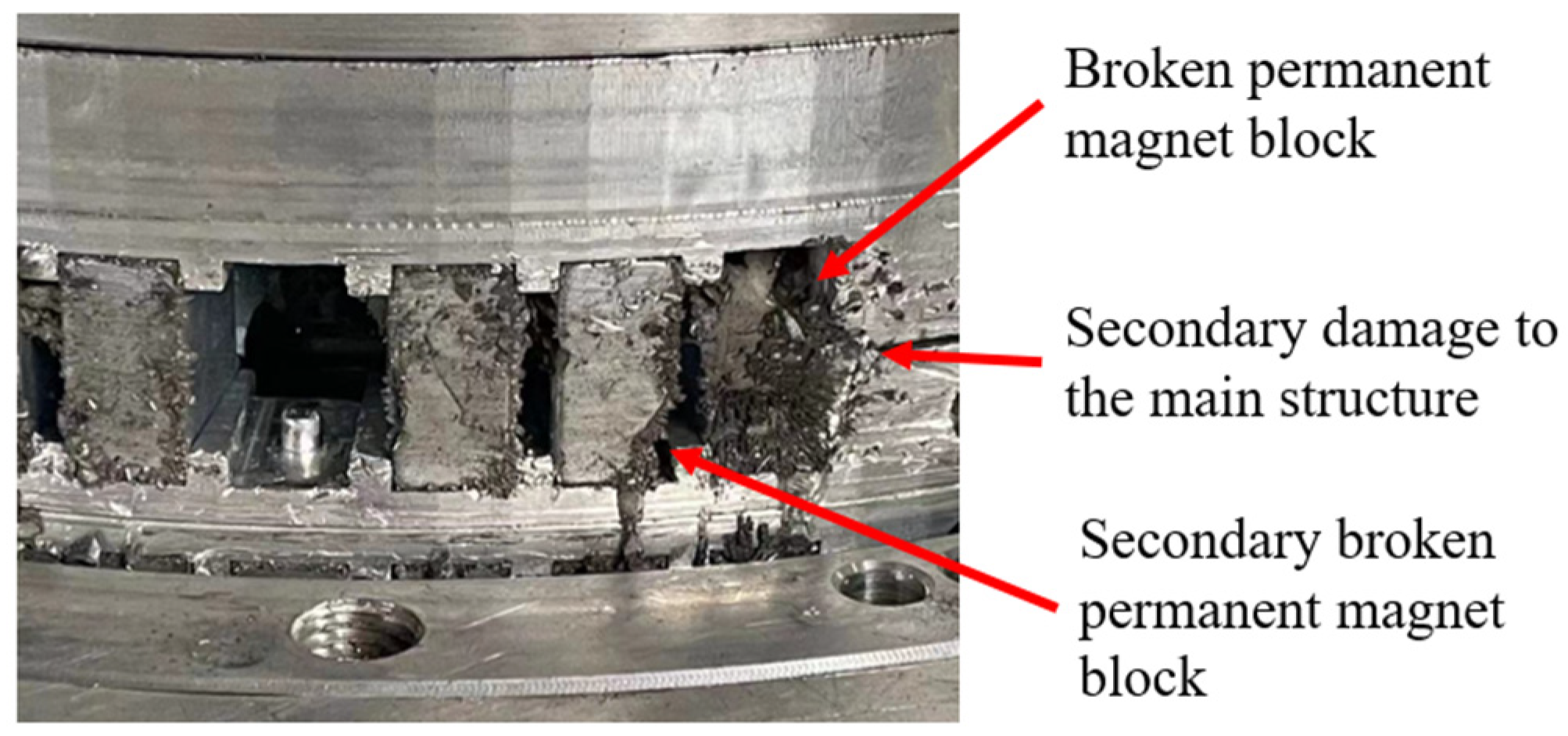
(1) Permanent magnet thrust bearings typically adopt the method of embedding permanent magnet rings directly into the bearing structure [
6]. This makes the assembly process more complex. Furthermore, if a single magnet is damaged, due to its direct embedding in the bearing mechanism, the damaged magnet could lead to secondary damage to the bearing structure and other magnets.
(2) Existing permanent magnet thrust bearings are often designed for specific machines [
20]. Their size, structure, and bearing capacity are tailored to meet the current design requirements, resulting in a lack of generalization and serialization capabilities. Additionally, their load-bearing capacity is often low, making them unsuitable for high-demand applications such as ship spindle propulsion.
(3) The theoretical models for permanent magnet thrust bearings are usually limited to single-layer cross-nested structures [
21]. There is a notable deficiency of well-defined theoretical models for multi-layer cross-nested structures. Moreover, the data on bearing capacity are commonly derived from theoretical calculations and simulations, often lacking rigorous experimental validation.
To address these limitations, this paper proposes a novel modular multi-unit cell permanent magnet thrust bearing. The research framework is depicted in
Figure 1, with the following contributions:
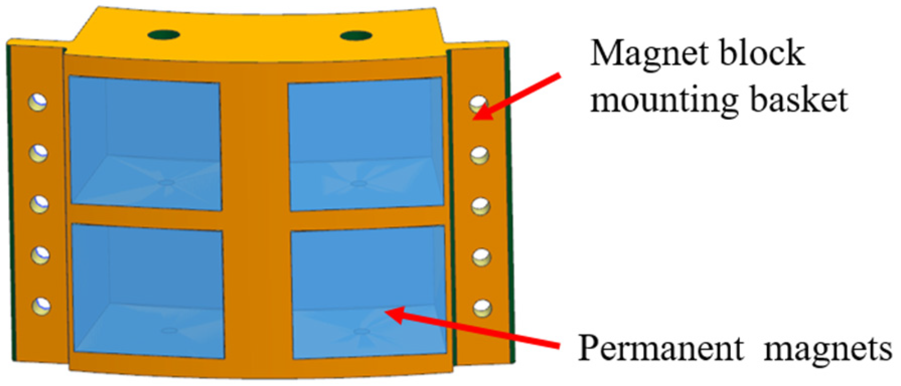
(1) Drawing inspiration from bionics and the honeycomb structure, a modular approach is adopted that incorporates a unit cell consisting of four permanent magnets. The design replaces the traditional permanent magnet ring, which is directly embedded in the bearing structure, with multiple connected unit cells. This separation allows the magnets to be isolated from one another, improving both durability and performance.
(2) By generalizing the unit cell structure and varying the number and arrangement of multiple unit cells, a flexible design with multiple nested and cross structures can be realized. This modular design enables the creation of a multi-unit cell permanent magnet thrust bearing adaptable to different configurations and requirements.
(3) The theoretical model for multi-layer cross-nested permanent magnet thrust bearings is derived and calculated based on the principles of virtual displacement and virtual work. This extension broadens the applicability of traditional models, which were previously limited to single-layer cross-nested structures, allowing for multi-layer cross-nested configurations. Additionally, an experimental platform for the permanent magnet thrust bearing is designed with a focus on ship spindle propulsion, and experimental validation is carried out to confirm the theoretical findings.
The main contents of this paper are organized as follows:
Section 1 is the introduction;
Section 2 outlines the structural design of a modular multi-unit cell permanent magnet thrust bearing, describing the general structure of the proposed permanent magnet thrust bearing, the magnet embedding and assembling methods, and the detailed structure of the magnet mounting baskets;
Section 3 provides the magnetic circuit analysis and theoretical calculations, describing the magnetic circuit of the proposed permanent magnet thrust bearing design, and the theoretical model of the multi-layer cross-nested structure is given through the principle of virtual displacement and the principle of linear superposition;
Section 4 includes the simulation analysis, in which, through the commercial finite element simulation software, a variety of cross-nested structures of the permanent magnet thrust bearing model are established, and the simulation work carried out according to the actual use of the working conditions;
Section 5 describes the experimental validation, in which an experimental platform for the permanent magnet thrust bearing is constructed, a prototype of the four-level nested quadrupole cross bearing is developed, and experimental tests are carried out; and
Section 6 is the conclusion.
4. Simulation Analysis
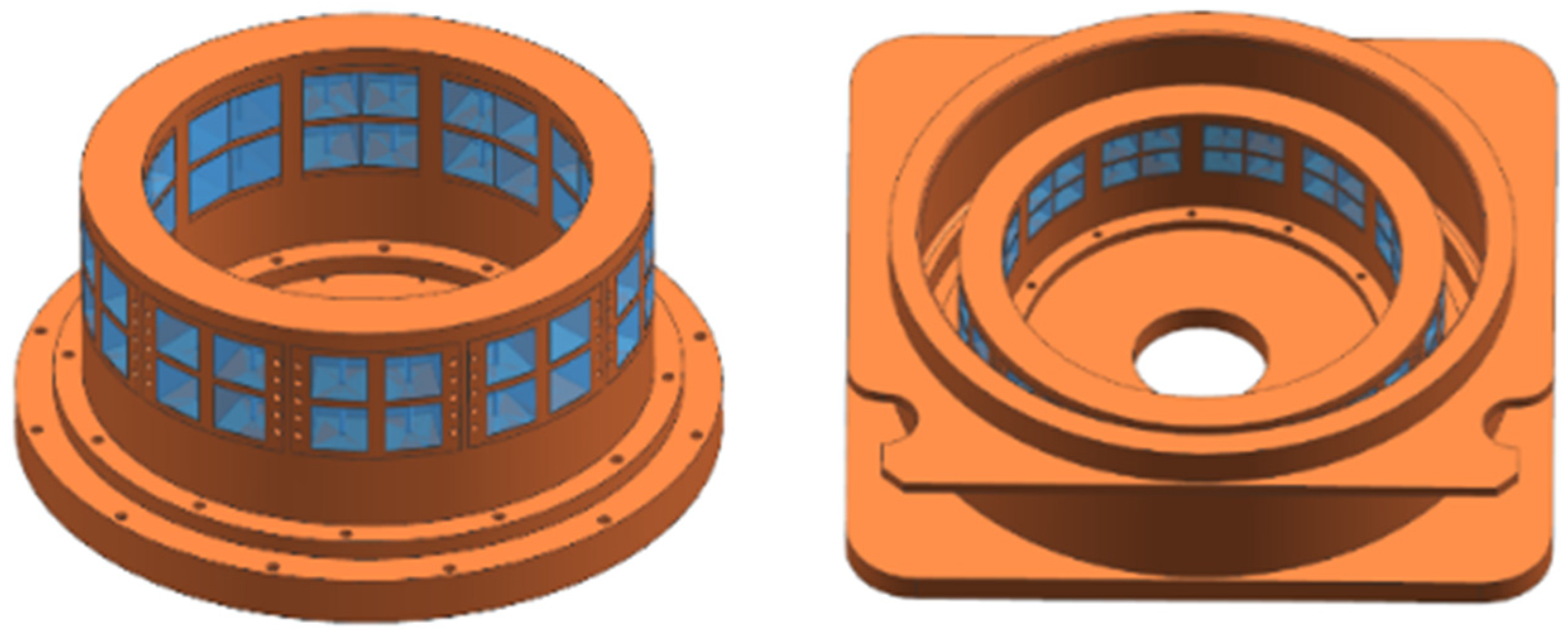
Finite element simulation is an important means of performance verification at the product design stage. In order to verify the load-carrying characteristics of the proposed modular multi-unit cell permanent magnet thrust bearing, four types of structures were developed based on the concepts of modularity and generalization. These included a two-layer nested two-pole crossover, a four-layer nested four-pole crossover, a six-layer nested six-pole crossover, and an eight-layer nested eight-pole crossover bearing. All models were constructed using commercial finite element software, and their bearing characteristics were analyzed. The different models utilize a generalized and modular unit cell structure, varying only in the number and arrangement of unit cells. This approach aimed to demonstrate the load-bearing characteristics of different layer nested and pole crossover configurations. The simulation models of the different structures are illustrated in
Figure 10. The red block indicates the rotor and the blue color indicates the stator.
Since the magnetic permeability of adiabatic materials and air in Ansoft/Maxwell 2023R1 software is almost identical, the basic structure of the bearing was simplified during the modeling process. The rotor and stator seats were excluded, and only the rotor and stator chokes, block mounting baskets, and permanent magnet blocks were retained. The four structural bearing models were then created by adjusting the number of permanent magnet blocks and their arrangement based on the number of layers in the rotor and stator. For the simulation, the motion domain settings of the permanent magnet thrust bearing were as follows: The rotor was assigned a motion domain, with the bearing speed set to 180 rpm. The axial displacement of the rotor was set to range from 2 mm to 30 mm, with a step size of 1 mm.
The basic parameters of the bearings are outlined in
Table 1. Given these parameters, the neutral axis diameter of bearings with different structures was consistent, and the performance characteristics of the permanent magnets were identical. The air gap between the permanent magnet rings was set at 2 mm. Additionally, the quantity of permanent magnets and unit cells varied among different structural configurations. The maximum diameter of the bearing was related to the number of nested layers, while the axial length was determined by the number of cross layers in the bearing. These parameters for different bearing structures are also summarized in
Table 1. This modeling and simulation approach enabled the evaluation of various structural configurations and their corresponding bearing characteristics, such as load capacity, stiffness, and displacement response.
Based on Ansoft/Maxwell software, simulation verification of bearings with different structures was carried out to analyze the bearing performance in the interval of axial displacement of 2–30 mm and the maximum bearing capacity of each layer was superimposed by Equation (16), to find out the maximum axial bearing capacity of the bearing as a whole.
where
F is the maximum total bearing capacity of the bearing,
k and
l denote the number of layers of the rotor and stator, respectively, and
Fk and
Fl are the bearing capacity of the
kth layer of the rotor and the
lth layer of the stator, respectively.
The bearing capacity of permanent magnet thrust bearings with different structures is shown in the
Figure 11 by comparing the finite element simulation results with the theoretical model. Overall, the axial bearing capacity of the bearing first increases and then decreases with the increase of axial displacement. This is because as the axial displacement of the bearing increases, the attraction and repulsion between the permanent magnets increase, limiting the further increase of the axial displacement. However, as the axial displacement continues to increase, the outermost layer of permanent magnets will gradually leave the working surface, resulting in a reduction in the working area and a decrease in the number of layers of permanent magnets that interact. This ultimately leads to a decrease in its axial bearing capacity. In addition, the images indicate that the maximum bearing capacity of the theoretical model is greater than that of the simulation model. This discrepancy arises from the construction of the equivalent magnetic circuit model, where the leakage flux from the outermost layer and the air gap is neglected. Additionally, the shaft material is treated as an ideal magnetic conductor, and its magnetic resistance is not considered. Consequently, the results of the theoretical analysis are higher than those obtained from the simulations. Moreover, in the theoretical model, the axial length of the permanent magnet bearing is calculated based on the combined length of four layers of permanent magnet rings, without accounting for the length of the unit cell. This leads to a difference in the axial displacement associated with the maximum bearing capacity of the two models. For the single structure bearing, the errors between the theoretical and simulation models are 0.7%, 3.5%, 1.2%, and 2%, respectively.
According to the simulation results, the unit cell bearing capacity and unit magnet block bearing capacity for different structures of the permanent magnet thrust bearing are shown in
Table 2. As the number of nested and cross layers in the bearing increases, both the unit cell and the unit magnet block bearing capacity also increase. This trend can be attributed to the higher ratio of the number of magnet layers to the working surface in the multilayer structure, which leads to a more efficient utilization of the magnetic field.
The increased magnet utilization in the multilayer cross-nested structure enhances the overall bearing capacity, as reflected in the higher unit cell and unit magnet block bearing capacities. These results validate the advantages of the multilayer cross-nested structure in improving the bearing’s load-carrying performance. By effectively using the available magnetic flux and optimizing the distribution of magnetic forces, the proposed structure significantly enhances the bearing’s overall efficiency and capacity.
6. Conclusions
In order to improve the load-carrying capacity and versatility of the permanent magnet thrust bearing, this paper has proposed a new modular multi-unit cell permanent magnet thrust bearing based on the design concept of bionics and a modular design scheme. By generalizing the unit cell structure, it can be constructed according to varying requirements, with different layers of nested and cross permanent magnet thrust bearings. The proposed bearing has been verified through theoretical calculations, finite element simulations, and experimental testing.
(1) Based on the design concept of bionics and referring to the structure of honeycombs, this paper adopted a modular and unit cell (composed of four permanent magnets and made universal) combination approach to construct different nested and cross structural configurations of permanent magnet thrust bearings, thereby enhancing the adaptability of permanent magnet thrust bearings in different scenarios.
(2) The theoretical model of the novel modular multi-unit cell permanent magnet thrust bearing was developed using the equivalent magnetic circuit method. By applying the principles of virtual displacement and virtual work, computational expressions for bearing capacity and stiffness were established. This theoretical model extends the traditional single-layer cross-nested structure to accommodate multi-layer cross-nested configurations, improving the model’s applicability.
(3) The bearing performance of the proposed permanent magnet thrust bearing was verified through finite element simulations and experimental testing. Based on the practical application scenario of ship spindle propulsion, a permanent magnet thrust bearing experimental platform was built, and a modular permanent magnet thrust bearing with a four-layer cross-nested structure was constructed for validation. The experimental results show that the maximum bearing capacity of the prototype is 48.45 kN, with a 7.3% error relative to the theoretical value and a 4% error relative to the simulation solution, demonstrating good accuracy.
Benefiting from the advantages of permanent magnet thrust bearings, such as quiet operation, vibration damping, and high rotational speed, this paper expands the traditional low-load permanent magnet thrust bearing to higher load ranges. The proposed modular multi-unit cell permanent magnet thrust bearing shows promising potential for applications in ship spindle propulsion. However, the existing range of applications for permanent magnet thrust bearings is still limited. Furthermore, due to the large quantity of permanent magnet materials used, the cost remains high compared to traditional bearings. In future research, efforts should focus on reducing the use of permanent magnet materials while maintaining load-carrying performance, in order to improve the competitiveness of permanent magnet thrust bearings in the market. The permanent magnet thrust bearing designed in this paper is a passive system. In the future, researchers in this field can explore the combination of permanent magnets and active control systems for the design of permanent magnet thrust bearings, so that the high efficiency of permanent magnets and the high precision of active control systems can be utilized at the same time, for example, the use of a passive permanent magnet structure in the substrate structure, and the use of active control systems in axial and radial precision control, so that a larger load-bearing capacity can be achieved based on the artificial active control system stiffness and other properties to meet the needs of more scenarios/conditions. This would allow the use of an active control system for precise axial and radial control, thus realizing a higher load-carrying capacity and artificial stiffness of the active control system to meet the needs of more scenarios/properties.


 and
and 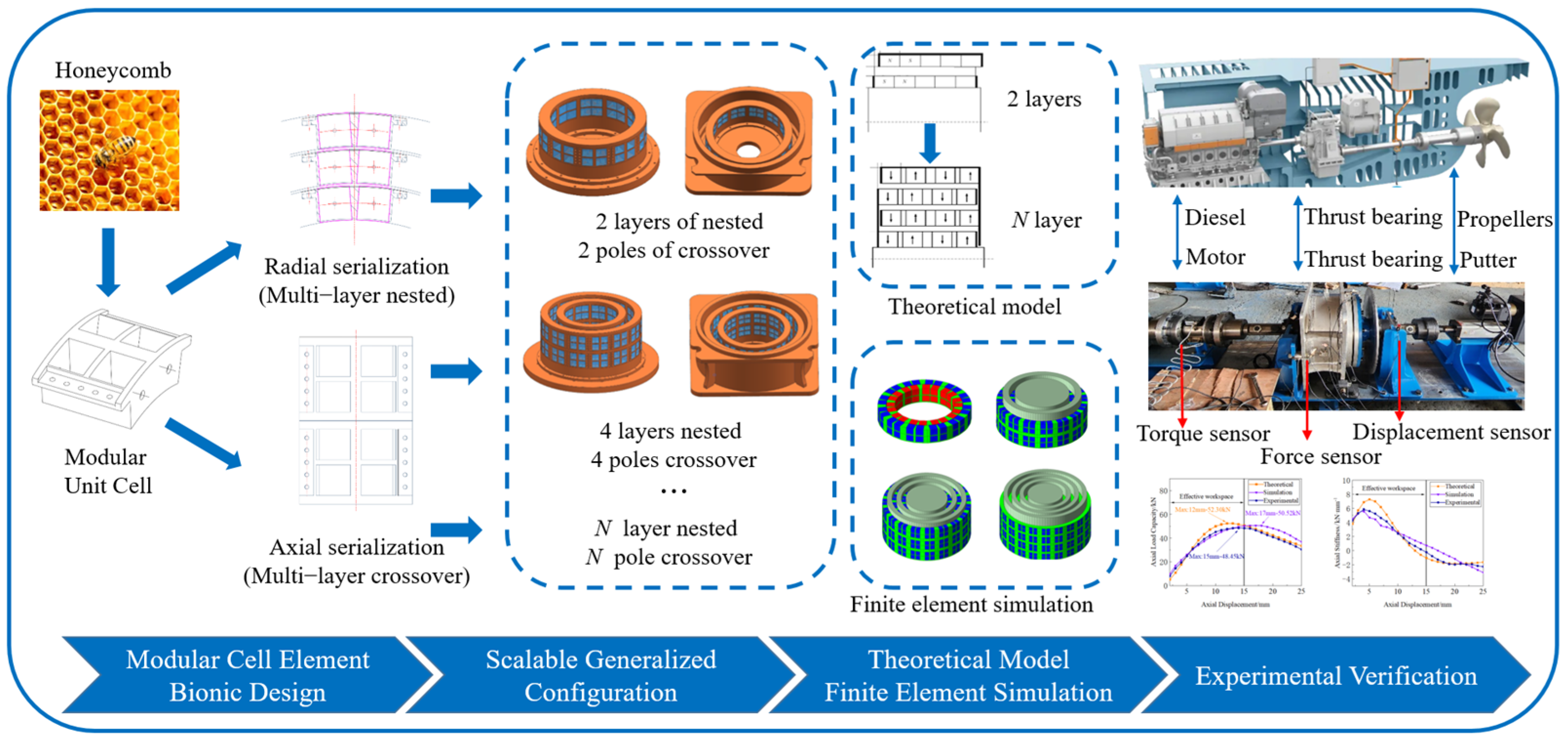


