Abstract
Elliptical superconducting cavities are widely used in particle accelerators because they can provide stronger acceleration fields than regular cavities. Pre-tuning is required to improve their performance, but the process is time-consuming. This research introduces an automated pre-tuning system for multi-cell elliptical superconducting cavities. This platform integrates three main components: real-time electric field measurements, data analysis based on tuning algorithms, and automated mechanical adjustment systems. During copper cavity tests, the system achieved an electric field flatness of 96.5%. Results show the system can accurately tune cavity frequencies while keeping electric fields uniform. This solves the problem of low efficiency in manual tuning. The new system improves cavity reliability and offers useful solutions for precise tuning needs. It also offers a foundational framework for analogous system development in future projects.
1. Introduction
Superconducting radio-frequency (SRF) cavity technology has become important for modern scientific equipment such as particle accelerators, free electron lasers (FELs), and medical proton therapy systems [1]. Unlike conventional copper cavities, SRF cavities operate at cryogenic temperatures (typically 2–4 K), where superconducting materials, such as niobium, exhibit near-zero resistive losses. This property allows SRF cavities to sustain extremely high accelerating gradients (up to 30 MV/m) while minimizing power dissipation, making them indispensable for modern high-energy applications [2]. The reduced power requirements and compact design enabled by SRF technology have revolutionized accelerator infrastructure, as demonstrated in large-scale projects like the European XFEL [3] and the Linac Coherent Light Source II (LCLS-II) [4].
A critical challenge in SRF cavities is achieving electric field flatness, which directly affects beam quality and acceleration efficiency. Field flatness refers to the uniformity of the axial electric field distribution across multi-cell cavities. Non-uniform fields will induce beam instabilities, increase transverse emittance, elevate the risk of field emission, and limit operational lifetimes [5]. Achieving high field flatness is particularly challenging due to manufacturing tolerances. Even minor deviations in cavity geometry (e.g., cell tilt > 0.1° or length errors > 0.2 mm) can reduce field flatness by more than 20%, as demonstrated in recent studies on 1.3 GHz elliptical cavities [6]. These challenges necessitate the development of advanced pre-tuning techniques to compensate for geometric imperfections.
Similar challenges have driven innovation in SRF cavity tuning in various installations around the world. The 508 MHz TRISTAN cavities at KEK [7] and the 704 MHz cavities at Brookhaven National Laboratory (BNL) [8] utilize semi-automated tuning systems, but these still require significant human intervention. DESY’s L-band cavity tuning platform [9] incorporates finite element analysis (FEA) to predict mechanical adjustments but still demands significant manual adjustments and iterative fine-tuning. These challenges highlight the need for a fully automated and high-precision tuning methodology to improve system adaptability and minimize human intervention.
The China Spallation Neutron Source (CSNS) is a multidisciplinary research platform that supports studies in material science, physics, chemistry, and life sciences and is the first spallation neutron source independently built in China. The CSNS generates a high neutron flux by directing a 1.6 GeV proton beam at a heavy metal target. It consists of three main components: the high-current proton accelerator, the target station, and the neutron scattering spectrometers. The Phase I construction aimed for a beam power of 100 kW, with an effective pulsed neutron flux of n/cm2·s and a pulse repetition frequency of 25 Hz [10]. The CSNS linear accelerator includes an ion source (IS), a low-energy beam transport (LEBT) line, a radio-frequency quadrupole (RFQ), a medium-energy beam transport (MEBT) line, a drift tube linac (DTL), and a linac-to-ring beam transfer (LRBT) line, and then reaches a rapid cycling synchrotron (RCS).
To meet growing user demand, the CSNS-II upgrade will increase the beam power to 500 kW. It will involve adding a superconducting linear accelerator after the existing DTL to increase the injection energy from 80 MeV to 300 MeV while boosting the average beam current from 62.5 µA to 312.5 µA, as illustrated in Figure 1. This upgrade requires 24 six-cell 648 MHz elliptical SRF cavities to accelerate proton beams from 165 MeV to 300 MeV. These cavities are fabricated using niobium stamping followed by precision electron beam welding and must meet stringent mechanical tolerances. Specifically, a coaxial deviation greater than 1 mm reduces field flatness below 96%, while a 0.5 mm length error degrades the field flatness to 70% [11]. Traditional tuning methods, which rely on multiple iterations of manual adjustments, are time-consuming and impractical for large-scale systems due to their labor-intensive nature and limited precision. These limitations drive the demand for advanced automated tuning systems.

Figure 1.
CSNS-II Linac layout.
A new pre-tuning platform was created specifically for 648 MHz elliptical cavities in the CSNS-II. It combines three main functions: instant field measurements, data analysis, and automated mechanical adjustments. The system achieved over 95% field uniformity and solved key problems in existing methods, such as manual operation delays and lack of feedback control. This work can accelerate progress in SRF cavity tuning in next-generation accelerators.
2. Development of the Pre-Tuning Machine
2.1. System Structure
The pre-tuning machine has two main components, as shown in Figure 2: a measurement module for cavity parameter testing (left) and a mechanical adjustment module for shape correction (right). Both sections can work alone or together as needed. The SRF cavity moves between areas on motorized rails.
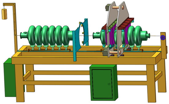
Figure 2.
Overall architecture of the pre-tuning machine.
Full automation from frequency measurement to tuning ensures fast, precise operation. Sensors continuously transmit real-time data to the control software, enabling dynamic adjustments. Special algorithms decide on tuning steps for each cavity unit, reducing human input. This live feedback makes tuning both faster and more accurate.
2.2. Resonant Frequency and Field Distribution Testing
The measurement system is a key part of the pre-tuning machine. It contains a network analyzer, a stepper motor, a small bead-pull system, and control software. The axial electric field flatness is measured using the bead-pull method based on perturbation theory [12,13]. As shown in Figure 3, a thin line runs through the cavity center. The weight is attached to one end for tension while the other end connects to a motorized wheel. A small metal bead is attached to the line, and as the stepper motor rotates the wheel, the bead moves along the axis of the cavity, perturbing its electromagnetic field. Probes at both cavities end to measure the S21 parameter via a vector network analyzer. Analyzing the correlation between the resonant frequency shift and the bead’s position enables the determination of the axial electric field distribution [14].
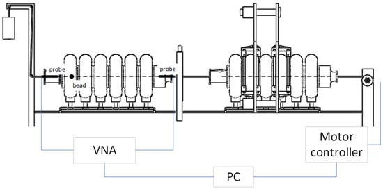
Figure 3.
Principle diagram of the resonant frequency and field flatness-testing system.
When the small bead moves inside the resonant cavity, the perturbations it generates at each point are directly related to the electric field E and magnetic field H at that location, as described by Equation (1) [15,16].
Here, U is the total stored energy of the resonant cavity, and represent the relative permittivity and permeability of the sphere relative to the vacuum, and denotes the volume of the sphere. Since the magnetic field at the central axis of the cavity vanishes , the equation simplifies to
The measurements were conducted using the phase comparison method, where the relationship between frequency and phase is expressed as
where is the loaded quality factor of the cavity, and denotes the phase shift.
The electric field flatness can then be calculated using the following formula [17]:
where and represent the maximum and minimum electric field values, and corresponds to the peak electric field distribution across all unit cells.
To achieve automation and high precision throughout the pre-tuning process, the data acquisition and control system plays an important role. This system collects resonant frequency and electric field data from the network analyzer in real time through an operating system and data acquisition module and calculates the tuning amount for each unit using a control module.
2.3. Coaxiality Testing
Coaxiality testing ensures that the cells of a multi-cell elliptical superconducting cavity are aligned along a common axis. This is essential for uniform electric field distribution and optimal performance. In this study, a coaxial testing ring is placed with its center aligned with the cavity’s axis.
Laser displacement sensors are mounted at equal angular intervals around the testing ring, as shown in Figure 4. These sensors measure the radial distance from the center of the testing ring to each cavity’s equatorial position. As the cavity moves through the ring, the sensors measure the diameters of each unit cavity, which can detect any axial misalignment.
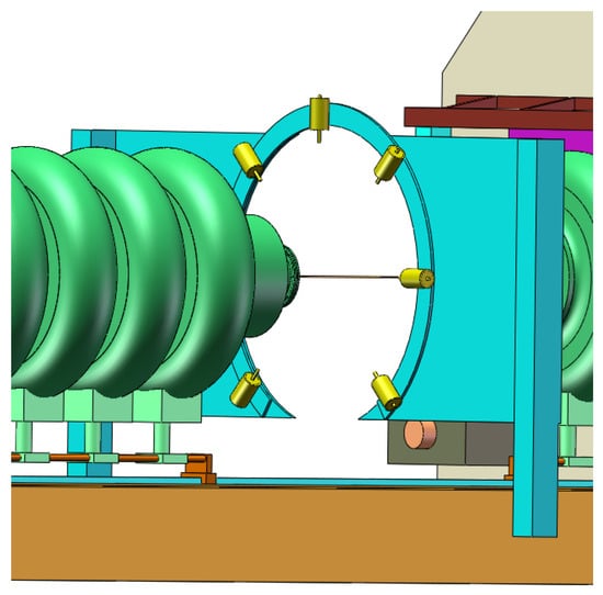
Figure 4.
Coaxiality testing assembly.
The data from the sensors are used to calculate the axial deviation of each cavity. The radial distance at each sensor position is compared to the expected values from the ideal cavity geometry. These deviations help assess the coaxiality of the entire multi-cell cavity.
To calculate coaxiality, the radial distances at each sensor position are analyzed. The deviations are averaged and used to determine the overall coaxiality. This method ensures precise alignment, minimizing field distortions that compromise the efficiency and stability of superconducting accelerator systems.
2.4. Equivalent Circuit Tuning Algorithm
The equivalent circuit model simplifies complex electromagnetic problems into circuit analyses [18]. It represents the electromagnetic field distribution in the superconducting cavity as interactions between inductance and capacitance. Using this model, the TM010- mode in multi-cell superconducting cavities can be effectively simulated as a resonant mode. In this approach, the equivalent circuit model can replace the distributed parameter circuit model. Figure 5 illustrates the equivalent circuit model for a six-cell superconducting cavity. The electromagnetic behavior of each unit can be modeled using an equivalent circuit, where L and C represent the equivalent inductance and capacitance of each unit, respectively [19,20]. Energy exchange occurs between adjacent cells through coupling capacitors. The resonant frequency of the cavity, along with its inductance and capacitance, is related by the following equation:

Figure 5.
Six-cell elliptical superconducting cavity equivalent circuit model.
For multi-cell cavities, the resonant frequency of each cell depends on its intrinsic inductance and capacitance, as well as coupling effects from neighboring cells. Coupling effects cause the overall cavity frequency to deviate from the independent resonant frequencies of individual cells. This phenomenon can be quantified by introducing a coupling coefficient. Introducing coupling capacitance further corrects the frequency of each cell. The coupling capacitance changes the effective capacitance of each unit in the equivalent circuit, resulting in a change in the resonant frequency. For the resonant frequency of each unit and the electric field distribution of each unit , is the cavity’s measured resonant frequency; since the coupling coefficient between middle units differs by less than 1%, the effect on the circuit distribution can be ignored, simplifying the coupling consistency between units. According to the equivalent circuit model and using Kirchhoff’s law, an equation set can be established to describe the relationships between the units:
In Equation (6), k represents half of the coupling coefficient between the cavity units:
The coupling coefficient k can be calculated by testing the resonant frequencies corresponding to different modes using Equations (7) and (8). The elliptical superconducting cavity operates in the TM010- mode. When the axial electric field is uniformly distributed, the electric field distribution of each unit satisfies the following relationship:
The corresponding relationship between the frequency of each unit and the cavity frequency is given by Equation (10):
In this case, the frequency of each unit can be expressed by the following relationship:
Let be the target frequency of each unit, and be the target frequency of the cavity, where , , . Based on the measured axial electric field distribution ratio and the frequencies of different modes, the theoretical and actual frequency differences of each unit can be calculated. This allows for the tuning of the frequency and length of each unit. Iterative adjustments via a pull-and-compression device fine-tune each cell’s shape, enabling alignment of the axial field distribution and resonant frequency with target specifications.
2.5. Pre-Tuning
Once all measurements of the elliptical superconducting cavity are completed in the testing area, the cavity is transferred to the tuning area for pre-tuning. The pre-tuning work is carried out using two fixed clamps and several movable clamps. When a unit requiring adjustment is identified, the cavity is moved to the position of the fixed clamps. These fixed clamps are equipped with three lead screws, displacement sensors, and motors arranged in a triangular configuration, as shown in Figure 6. Under motor control, the distance and angle between the two fixed clamps can be adjusted, thereby adjusting the state of the unit cavity to be tuned and completing the pre-tuning process. Once tuning is complete, the clamps disengage and the cavity is repositioned to adjust subsequent units. This process is repeated until all unit cavities are tuned.
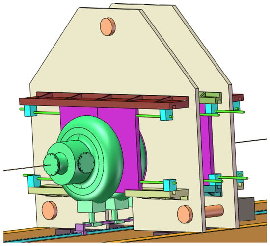
Figure 6.
Pre-tuning clamp assembly.
The adjustment of the fixed clamps is driven by stepper motors, which can be automated through programmatic control. Once the pre-tuning is completed, the high-frequency characteristics of the cavity can be measured using the bead-pull method. If the test results do not meet the expected criteria, the pre-tuning process is repeated. This cycle continues until the desired performance metrics of the cavity are achieved.
2.6. Software Control Architecture
To enable full automation of the pre-tuning machine, a dedicated software control system was developed using LabVIEW 2013. The software architecture integrates with two synchronized interfaces, one for the measurement area and another for the tuning area, to coordinate testing and adjustment processes seamlessly, as is shown in Figure 7.
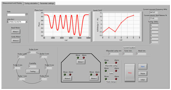
Figure 7.
The pre-tuning software interface.
The measurement area interface manages real-time data acquisition and analysis. It communicates with the network analyzer via GPIB protocol to acquire S21 parameters and synchronizes with the bead-pull system’s stepper motor to control bead movement along the cavity axis. Perturbation theory-based algorithms process phase-frequency shifts to generate axial electric field profiles. Simultaneously, laser displacement sensors provide coaxial data into the system. All measurement results are compiled into tuning prescription files that define target frequency corrections and field flatness thresholds for individual cells [21].
In the tuning area interface, these prescription files drive closed-loop mechanical adjustments. The software controls multiple stepper motors through RS-485 communication, executing micron-level clamp displacements predicted by a nonlinear displacement-frequency model. Safety protocols include real-time monitoring of piezoelectric force sensors and optical encoders. If clamping forces or displacements exceed the thresholds, the system initiates an emergency retraction sequence and logs fault codes for diagnostics To enhance operational flexibility, the software retains manual tuning functionalities, enabling users to perform fine adjustments or calibration when necessary.
A state machine architecture governs the interaction between the two areas, ensuring no conflicting operations occur. During operation, the measurement area completes field characterization and locks the cavity in a stationary state before transferring control to the tuning area. A unified dashboard displays real-time progress metrics, including field flatness improvements, frequency convergence trends, and system health indicators. This architecture reduces manual intervention, initial parameter configuration, and final validation, which greatly shortens the adjustment cycle compared to manual methods during experimental testing.
3. Experimental Application
3.1. Experimental Setup and Initial Testing
The pre-tuning machine was deployed to validate its functionality and performance using copper test cavities as substitutes for superconducting cavities. The experimental setup, as illustrated in Figure 8, consisted of a network analyzer, a bead-pull system, and a tuning platform. The initial phase of the experiment focused on setting up the system and addressing a list of technical challenges below:
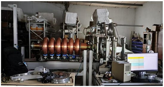
Figure 8.
Experimental setup.
1. Network analyzer malfunction: during initial testing, the malfunction of the portable network analyzer failed to scan the field distribution.
2. Mechanical adjustments: Installation of clamps on the copper cavity revealed mechanical inconsistencies that necessitated modification to the clamps. Only two pairs of clamps could be installed initially, while the rest required adjustments to fit the cavity’s uneven surface.
3. Bead-pull system optimization: The initial bead-pull system used a small-diameter bead, which caused issues with smooth movement. For bead selection, the frequency shift must exceed the test system’s frequency stability requirements while remaining within the perturbation regime; beads with excessively large or small volumes are unsuitable. Ultimately, a 3 mm diameter aluminum bead was chosen. Furthermore, the line must be thin, non-elastic, and non-metallic; the diameter should also be minimized to avoid perturbing the cavity’s RF characteristics. This was resolved by replacing the line with a fishing line, which improved the system’s reliability and ensured consistent measurements, as shown in Figure 9.
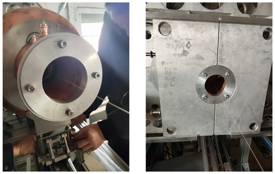
Figure 9.
The bead-pull system with a fishing line.
3.2. Pre-Tuning Process and Observations
The pre-tuning process involved iterative measurements and adjustments to achieve the target frequency of 648 MHz and a field flatness of over 95%. The process was divided into several key steps shown below, which provided valuable insights into the cavity’s behavior during tuning.
1. Initial field distribution: Before pre-tuning, the copper cavity exhibited poor field flatness, with a calculated flatness of approximately 2%, its S21 phase curve shown in Figure 10 by a network analyzer [22]. The start and stop frequencies of the network analyzer were set to the cavity’s mode resonant frequency. With the setting of appropriate sweep time and number of sweep points and the synchronization of these parameters with the bead movement, the phase distribution can be measured. By observing the phase minima in each cell (the trough positions in the curve), the electric field flatness can be calculated, and the subsequent tuning strategy can be determined. The target frequency was set at 648 MHz, and the goal was to improve the field flatness to above 95%.
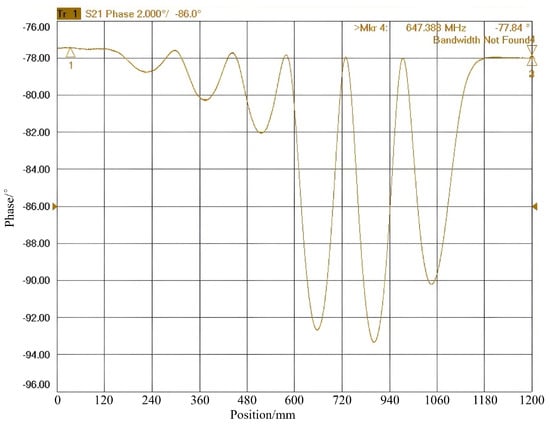
Figure 10.
Field distribution of the elliptical superconducting cavity before pre-tuning.
2. Tuning mechanism: The pre-tuning process relied on compressing or stretching individual cell units to adjust their equivalent capacitance, as depicted in Figure 11. Compression increases a cell’s capacitance, thereby reducing resonant frequency and field amplitude, while stretching has the opposite effect. This principle was used to fine-tune the cavity’s performance.
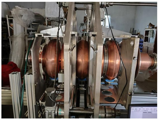
Figure 11.
Compress or stretch the individual cell units.
The relationship between the pre-tuning machine’s travel distance and frequency change was nonlinear. Initially, a 1 mm travel distance resulted in a frequency shift of approximately 10 kHz, but this shift increased to several hundred kHz in later stages.
During tuning, the copper cavity underwent elastic deformation (causing temporary frequency shifts) and plastic deformation (resulting in permanent adjustments). For example, compressing Cell-4 temporarily reduced the frequency to 647.559 MHz, but upon release, the frequency stabilized to 647.673 MHz after the cavity rebounded.
3. Iterative tuning and measurement: The tuning process was performed iteratively, with each cell adjusted individually. After each adjustment, the high-frequency characteristics were re-measured to evaluate the impact of the tuning. This cycle was repeated multiple times until the desired electric field flatness was achieved [23]. The changes in field distribution during the tuning process are illustrated in Figure 12.
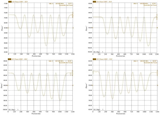
Figure 12.
Changes of the electric field during the pre-tuning process.
Adjusting a single cell often impacts adjacent cells, especially end cells, which interact with two neighboring cells. For example, stretching Cell-1 by 18 mm increased its frequency but also caused a slight frequency shift in Cell-2.
4. Final results: After multiple iterations of tuning and measurement, the field flatness of the superconducting cavity was successfully improved from an initial 2% to 96.5%, as shown in Figure 13. The final results met the target requirements, demonstrating the effectiveness of the pre-tuning machine algorithm and tuning device. The resonant frequency was stabilized to 648 MHz, with a field distribution that satisfied the design specifications.
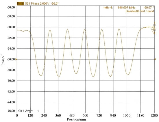
Figure 13.
Field distribution of the elliptical superconducting cavity after pre-tuning.
3.3. Challenges and Limitations
There were several challenges encountered during the experiment, and each provided valuable insights for future improvements. Some of the challenges and limitations are described below:
1. Mechanical limitations: The high yield strength of copper and niobium materials, combined with the large size of the cavity structure, makes them resistant to deformation, requiring a large amount of force for adjustment. This makes manual tuning difficult and prevents simultaneous adjustments in multiple orientations, which can easily affect coaxiality. This highlighted the need for high-strength and robust mechanical components in the pre-tuning machine in order to handle the high-stresses during adjustment.
2. Motor control: The stepper motors exhibited issues with lost steps while operating at higher speeds, which necessitated lower operating speeds (below 2000 steps per second) to ensure accuracy. This needs to be considered when optimizing the motor control algorithm to achieve precise adjustments.
3. Sensor calibration: The displacement and pressure sensors required careful calibration to ensure accurate measurements. Any misalignment or calibration error could lead to inaccurate tuning results, underscoring the need for high-precision sensors in the system.
4. Conclusions and Discussion
The multi-cell elliptical cavity pre-tuning machine developed in this study represents a significant advancement in superconducting cavity frequency tuning technology. By integrating an automatic measurement system, iterative tuning algorithms, close-loop feedback control, and an automated pre-tuning device, the system achieves high-precision adjustment of cavity frequency and electric field flatness. Compared to traditional manual tuning methods, the automated pre-tuning machine significantly reduces tuning time, provides accurate tuning parameters, enhances process stability, and ensures reliable operation of cavities under high acceleration gradients. Experimental results show that the system improves the field flatness of copper test cavities from 2% to 96.5% and stabilizes the resonant frequency to 648 MHz.
By incorporating the bead-pull system, laser sensors for coaxiality monitoring, and motor-driven fixtures for cavity deformation measurement, the pre-tuning machine can automatically perform high-frequency, coaxiality testing, adjustment, and tuning of the cavity as an integrated process. It optimizes the tuning algorithm, reduces manual intervention, addresses the tuning challenges of large structures, and significantly improves efficiency and consistency.
The experimental data further validates the theoretical framework proposed in this study, particularly the frequency shifts observed during cavity compression and stretching, which align closely with the predictions of the equivalent circuit model. Additionally, the coupling effect between cells was confirmed, as stretching Cell-1 caused a 0.03 MHz frequency shift in Cell-2, which is consistent with the theoretical coupling coefficient analysis. These experimental findings not only establish the high precision of the system but also demonstrate its adaptability to complex superconducting cavity systems.
Despite the system’s exceptional tuning performance and enhanced automation, several challenges were observed during the experiments. First, the high yield strength of copper cavities (207 MPa) requires strong forces for shaping, making precise control difficult. Higher-strength fixture designs are needed to provide the strong forces needed for adjustment. Secondly, a nonlinear relationship between displacement and frequency was observed, especially during large physical adjustments. Adaptive control algorithms will help to optimize the adjustment process. Additionally, stepper motor movements are problematic at high speeds, while sensors gradually lose their accuracy when operating for a long time. Future work should prioritize sub-micron motor control precision and sensor calibration protocols resistant to thermal drift.
The results of this study show that the system works in laboratory settings and can be used in large-scale accelerator projects. This system will be used in the CSNS-II to optimize elliptical superconducting cavities for stable 500 kW beam operation. Its modular design allows adaptation to other systems requiring precise field control, including medical proton therapy devices. Next-stage research will explore machine learning algorithms to optimize adjustment paths and reduce tuning cycles. Standardized adjustment tools should also be developed for different cavity types, such as the 1.3 GHz Tesla-style cavities and medical proton therapy spherical cavities, to increase system flexibility.
The pre-tuning machine developed in this study provides an efficient, stable, and scalable automated solution for optimizing the performance of superconducting cavities. With the ability to achieve electric field flatness of more than 95%, the system can enhance cavity tuning accuracy and also provide robust technical support for future applications. With further algorithmic refinements and cost optimization, this system holds promise for applications in accelerator physics and compact medical proton therapy systems.
Author Contributions
Conceptualization, A.L. and L.M.; methodology, A.L. and H.L.; software, A.L. and Q.C.; validation, A.L. and Y.Y.; formal analysis, B.L.; investigation, X.W.; data curation, Y.Y. and P.Q.; writing—original draft preparation, A.L.; writing—review and editing, P.Q.; visualization, W.Z.; supervision, M.F.; project administration, A.L. and C.Z. All authors have read and agreed to the published version of the manuscript.
Funding
This study was funded by Guangdong Basic and Applied Basic Research Foundation, China, grant number 2020A1515110579.
Institutional Review Board Statement
Not applicable.
Informed Consent Statement
Not applicable.
Data Availability Statement
The original contributions presented in this study are included in the article. Further inquiries can be directed to the corresponding author (liah@ihep.ac.cn).
Conflicts of Interest
The authors declare no conflict of interest.
References
- Padamsee, H. RF Superconductivity: Science, Technology, and Applications; Wiley-VCH Verlag GmbH & Co. KGaA: Weinheim, Germany, 2009. [Google Scholar]
- Gurevich, A. Theory of RF superconductivity for resonant cavities. Supercond. Sci. Technol. 2017, 30, 034004. [Google Scholar] [CrossRef]
- Choroba, S. The high power RF system for the European XFEL. In Proceedings of the 29th Linear Accelerator Conference, LINAC2018, Beijing, China, 16–21 September 2018; pp. 601–604. [Google Scholar]
- Gonnella, D. Commissioning and first operation of the LCLS-II linac. In Proceedings of the 21st International Conference on RF Superconductivity, Grand Rapids, MI, USA, 25–30 June 2023; Available online: https://accelconf.web.cern.ch/srf2023/talks/moiaa04_talk.pdf (accessed on 25 March 2025).
- De Prisco, R.; Zeng, R.; Czuba, K.; Lesniak, T.; Papis, R.; Sikora, D.; Zukocinski, M. Influence of the Cavity Field Flatness and Effect of the Phase Reference Line Errors on the Beam Dynamics of the ESS Linac. In Proceedings of the 61st ICFA Advanced Beam Dynamics Workshop on High-Intensity and High-Brightness Hadron Beams (HB2018), Daejeon, Republic of Korea, 17–22 June 2018; pp. 377–382. Available online: https://portal.research.lu.se/en/publications/influence-of-the-cavity-field-flatness-and-effect-of-the-phase-re (accessed on 25 March 2025).
- Shemelin, V.; Carriere, P.R. Frequency control in the process of a multicell superconducting cavity production. Rev. Sci. Instrum. 2012, 83, 043304. [Google Scholar] [CrossRef] [PubMed]
- Tajima, T.; Furuya, T.; Suzuki, T.; Lino, Y. Pre-tuning of TRISTAN superconducting RF cavities. In Proceedings of the 4th Workshop on RF Superconductivity, Tsukuba, Japan, 14–18 August 1989; pp. 14–18. Available online: https://accelconf.web.cern.ch/SRF89/papers/srf89g30.pdf (accessed on 25 March 2025).
- Xu, W.; Astefanous, C.; Belomestnykh, S.; Ben-Zvi, I.; Cole, M.; Deacutis, J.; Hahn, H.; Holmes, D.; Jain, P. Progress on the high-current 704 MHz superconducting RF cavity at BNL. In Proceedings of the IPAC2012, New Orleans, LA, USA, 20–25 May 2012; Available online: https://accelconf.web.cern.ch/ipac2012/papers/weppc113.pdf (accessed on 25 March 2025).
- Thie, J.H.; Goessel, A.; Iversen, J.; Klinke, D.; Möller, W.D.; Müller, C.; Peters, H.B.; Bhogadi, D.; Carcagno, R.H.; Khabiboulline, T.N.; et al. Commissioning and upgrade of automatic cavity tuning machines for the European XFEL. In Proceedings of the 15th SRF Conference, Chicago, IL, USA, 25–29 July 2011; pp. 495–500. Available online: https://epaper.kek.jp/SRF2011/papers/tupo048.pdf (accessed on 25 March 2025).
- Zhou, Q.; He, F.; Pan, W.; Li, Z.; Yang, J. Development of a superconducting radio frequency double spoke cavity for CSNS. Nucl. Instruments Methods Phys. Res. Sect. A Accel. Spectrometers Detect. Assoc. Equip. 2021, 988, 164873. [Google Scholar] [CrossRef]
- Li, B.; Liu, H.; Wang, Y.; Wu, X.; Li, A.; Qu, P.; Fan, M.; Chen, Q. Simulating analysis on electric field flatness of deformed superconducting elliptical cavity for CSNS-II linac. High Power Laser Part. Beams 2021, 33, 034001. [Google Scholar] [CrossRef]
- Schmuser, P. Tuning of Multi-Cell Cavities Using Bead Pull Measurements. Superconducting Radio-Frequency Group Reports. 1992. Available online: https://www.classe.cornell.edu/public/SRF/1992/SRF920925-10/SRF920925-10.pdf (accessed on 25 March 2025).
- Yin, X.J.; Li, A.H.; Xiao, Y.C.; Chen, Q.; Liu, H.C.; Gong, K.Y.; Fu, S.N. Preliminary study on the RF tuning of CSNS DTL. Chin. Phys. C 2014, 38, 027002. [Google Scholar] [CrossRef][Green Version]
- Yang, J.; Ma, Z.; Wang, Y.; Hou, H.; Li, Z.; Luo, C.; Mao, D.; Shi, J.; Liu, J. Simulation of a 1500 MHz 5-cell superconducting cavity. Nucl. Tech. 2015, 38, 17–28. [Google Scholar] [CrossRef]
- Maier, L.C., Jr.; Slater, J.C. Field strength measurements in resonant cavities. J. Appl. Phys. 1952, 23, 68–77. [Google Scholar] [CrossRef]
- Zhang, H.; Yang, L.; Wang, F.; Lin, L.; Feng, Z. Field distribution measurement system based on LabVIEW and perturbation method: Design and performance. Nucl. Electron. Detect. Technol. 2012, 32, 7–10. [Google Scholar]
- Tang, Z.; Ma, Z.; Hou, H.; Mao, D.-Q.; Feng, Z.-Q.; Wang, Y.; Xu, K.; Luo, C.; Li, Z.; Shi, J.; et al. Frequency control and pre-tuning of a large aperture 500 MHz 5-cell superconducting RF cavity. Nucl. Sci. Tech. 2014, 25, 030102. [Google Scholar] [CrossRef]
- Padamsee, H.; Knobloch, J.; Hays, T. RF Superconductivity for Accelerators; John Wiley & Sons: New York, NY, USA, 2008. [Google Scholar]
- Fernandes, P.; Parodi, R. On compensation of axial electric field unflatness in multicell accelerating structures. Part. Accel. 1984, 14, 185–199. Available online: https://cds.cern.ch/record/1108008/files/p185.pdf (accessed on 25 March 2025).
- Sekutowicz, J.; Yinghua, C.; Yixiang, W. A different tuning method for accelerating cavities. In Proceedings of the Workshop on RF Superconductivity. KEK, Tsukuba, Japan, 14–18 August 1989; pp. 849–857. Available online: https://www.jacow.org/SRF89/papers/SRF89G31.pdf (accessed on 25 March 2025).
- Zhang, J.; Huang, H.; Xu, B.; Lin, H.; Sun, Y.; Pan, W. Data acquisition system of superconducting cavity test based on Labview. Nucl. Electron. Detect. Technol. 2013, 33, 1098–1103. Available online: https://inis.iaea.org/records/rtkcx-72p37 (accessed on 25 March 2025).
- Shishido, T.; Kako, E.; Noguchi, S. Development of pre-tuning system for 972 MHz 9-cell superconducting cavities. In Proceedings of the 11th Workshop on RF Superconductivity, Lübeck & Travemünder, Germany, 8–12 September 2003; Available online: https://epaper.kek.jp/SRF2003/papers/tup42.pdf (accessed on 25 March 2025).
- Guo, Z.; Li, Z.; Zhai, J.; Yu, J.; Zhao, T.; Gao, J. Pretuning of 1.3 GHz 9-cell Ichiro copper cavity. High Power Laser Part. Beams 2011, 23, 175–178. Available online: https://www.hplpb.com.cn/article/id/4445 (accessed on 25 March 2025).
Disclaimer/Publisher’s Note: The statements, opinions and data contained in all publications are solely those of the individual author(s) and contributor(s) and not of MDPI and/or the editor(s). MDPI and/or the editor(s) disclaim responsibility for any injury to people or property resulting from any ideas, methods, instructions or products referred to in the content. |
© 2025 by the authors. Licensee MDPI, Basel, Switzerland. This article is an open access article distributed under the terms and conditions of the Creative Commons Attribution (CC BY) license (https://creativecommons.org/licenses/by/4.0/).