Abstract
In Europe, renewable energy sources such as photovoltaic panels and wind power plants are developing dynamically. The growth of renewable energy is driven by rising energy prices, greenhouse gas emission restrictions, the European Union’s Green Deal policy, and decarbonization efforts. Photovoltaic farms generate energy intermittently, depending on weather conditions. Given the increasing number of new installations, ensuring the power balance and transmission capacity of the electrical grid has become a major challenge. To address this issue, the authors propose a technical solution that allows the energy generated by photovoltaic systems to be stored in the form of heat. Thermal energy from solar power and wind energy offers significant potential for energy storage. It can be accumulated during summer in specially designed sand-based heat storage systems and then used for heating purposes in winter. This approach not only reduces heating costs but also decreases greenhouse gas emissions and helps balance the power grid during sunny periods. Post-industrial areas, often located near city centers, are suitable locations for large-scale heat storage facilities supplying, among others, public utility buildings. Therefore, this article presents a concept for utilizing high-temperature sand-based heat storage systems built in decommissioned underground mining excavations.
1. Introduction
Rising energy prices, decarbonization, the Green Deal policy, and the development of renewable energy sources are the main factors encouraging the development and construction of energy storage facilities. Energy can be stored in various forms: electrical, thermal, kinetic, or chemical energy [1,2,3,4]. Energy storage facilities can be built as small home storage facilities, but also in the form of energy hubs connected to renewable energy sources. Post-industrial areas where the transformation related to the decarbonization policy of the European Union is taking place can be used for the construction of state-of-the-art energy storage facilities [5,6]. The authors focused on thermal energy storage. The main idea of these storage facilities is to collect thermal energy during overproduction of energy from renewable energy sources, especially in the summer, to use this energy during the heating season.
In Poland, the renewable energy sector is developing dynamically. In 2024, electricity production from renewable energy sources (RESs) accounted for 30% of the energy mix. The largest share among RESs comes from photovoltaic (PV) installations, which currently constitute 62.9%. The second most significant component of RESs is wind power, contributing 30.16%. The rapid growth of photovoltaic installations is evident in the installed capacity of PV systems, which reached 12.42 GW at the end of 2022, 17.08 GW at the end of 2023, 17.73 GW at the end of the first quarter of 2024, and 21.2 GW by the end of December 2024 [7,8,9].
The rapidly growing number of photovoltaic (PV) installations faces a significant challenge in balancing energy surpluses. This issue is linked to the temporary restriction of electricity production during periods of energy surplus. Initially, such situations occurred only on weekends and holidays, but they are now increasingly happening on weekdays as well. For example, in May 2024, the electricity transmission system operator, PSE, ordered photovoltaic farms to reduce production for 14 days to balance the national power system. Another issue related to the inability to balance PV-generated energy is the high percentage of refusals for connecting new PV installations to the grid. In 2023 alone, connection requests for up to 83.6 GW of PV capacity were denied [10,11].
Another major issue in Poland is poor air quality. Air pollution, particularly the frequent exceedance—sometimes by several hundred percent—of the permissible levels of PM10 and PM2.5 particulate matter, is most common during the winter (heating) season. One of the main causes of smog in many areas is so-called low emissions, which result from the burning of solid fuels (often low-quality) by private individuals for heating purposes. This phenomenon negatively affects both the quality of life and the natural environment.
In search of a solution to both issues—the challenge of balancing electricity generation and air pollution—the authors propose an innovative system that utilizes photovoltaic farms and other renewable energy sources, such as wind turbines, to produce heat, which can be stored in inactive mining excavations. This approach helps mitigate the problem of surplus electricity, particularly on sunny summer days, while also reducing air pollution and the emission of harmful gases, including greenhouse gases, during winter when the stored heat is used [6].
Waste heat from industrial plants can also be used for heat storage. The presented idea concerns seasonal thermal energy storage. There are also short-term thermal energy storage facilities. They are used to optimize and equalize the daily load, e.g., in thermal power plants [12,13,14,15]. Taking into account the above facts, this work aimed at setting new directions in the creation of energy storage facilities and suggesting new concepts will contribute to the diversification of energy sources and adaptation of energy systems to modern and ecological trends prevailing in the European Union. In this article, the authors want to present an innovative approach taking into account the possibility of using the decommissioned mine workings for building seasonal heat storage facilities. As part of the prepared concept, three variants of a thermal energy storage facility have been developed, which can be used both on a small scale (demonstrator) and on a large scale to meet the needs of local heat consumers (cities, communes, counties, public buildings, or housing estates).
- Seasonal thermal storage
In recent years, energy storage has become an important part of renewable energy technology systems [6,16]. Thermal energy storage (TES) is a technology that stores energy by heating or cooling a storage medium so that the stored energy can later be used for heating and cooling, as well as for power generation [17]. The advantages of using the thermal energy storage in the energy system include an increase in overall efficiency and greater reliability, as well as reduced investment and operating costs [18]. Due to the enormous scale of thermal energy consumption, any improvements in thermal energy management practices could bring significant benefits to society [19]. Seasonal thermal energy storage (STES) is a highly efficient energy use system that uses heat carriers to store and use thermal energy in cycles, which is key to achieving low and zero carbon emissions [12,20,21,22,23].
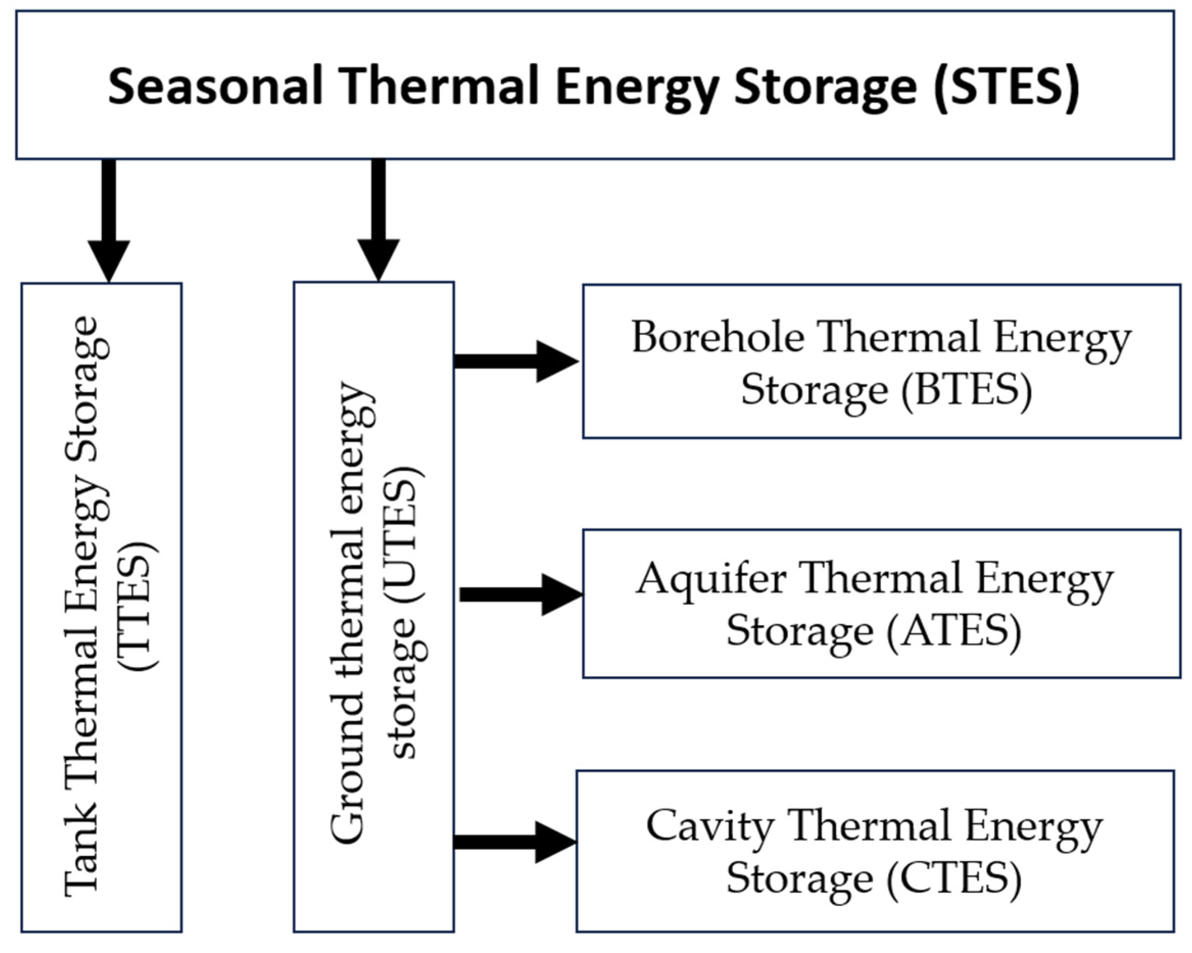
One of the criteria for dividing seasonal heat storage is the division according to the type of heat storage medium. Sample systematics of the seasonal thermal energy storage methods are presented in Figure 1. Thermal energy storage methods include the following:
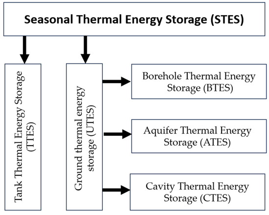
Figure 1.
Division of the methods for seasonal thermal energy storage.
- Aquifer Thermal Energy Storage (ATES) [1];
- Borehole Thermal Energy Storage (BTES) [2,5];
- Cavity Thermal Energy Storage (CTES) [16,17];
- Tank Thermal Energy Storage (TTES) [2].
The thermal energy that can be stored in the warehouse may come from a solar installation and also from the so-called waste heat that is generated, e.g., in manufacturing processes. Then, the effect of heat storage will be much greater (even twice) and fundamentally more economical. Moreover, the use of underground thermal energy storage systems (UTESs) enables the collection and storage of excess heat generated in summer and then its recovery and use for heating in winter. In this way, the efficiency of using the solar systems increases significantly.
According to the literature data, the optimal working medium used in the seasonal thermal energy storage should have the following parameters [18]:
- high heat capacity;
- high energy stability (stored thermal energy);
- high chemical stability (in the case of water);
- low operating costs;
- environmental neutrality.
Energy storage can be characterized by the following parameters [19]:
- capacity, which determines the amount of energy that can be stored. This depends on the storage method (technology), the medium used, and the size of the system;
- storage unit power, i.e., quantity determining how quickly the storage unit can be charged or discharged;
- system efficiency, i.e., the ratio of energy supplied to the user to the energy needed to charge the warehouse—this value takes into account energy losses during storage as well as losses during charging and discharging the battery;
- storage period;
- charging and discharging time;
- costs related to efficiency—this value depends on capital expenditure and operational life of the system.
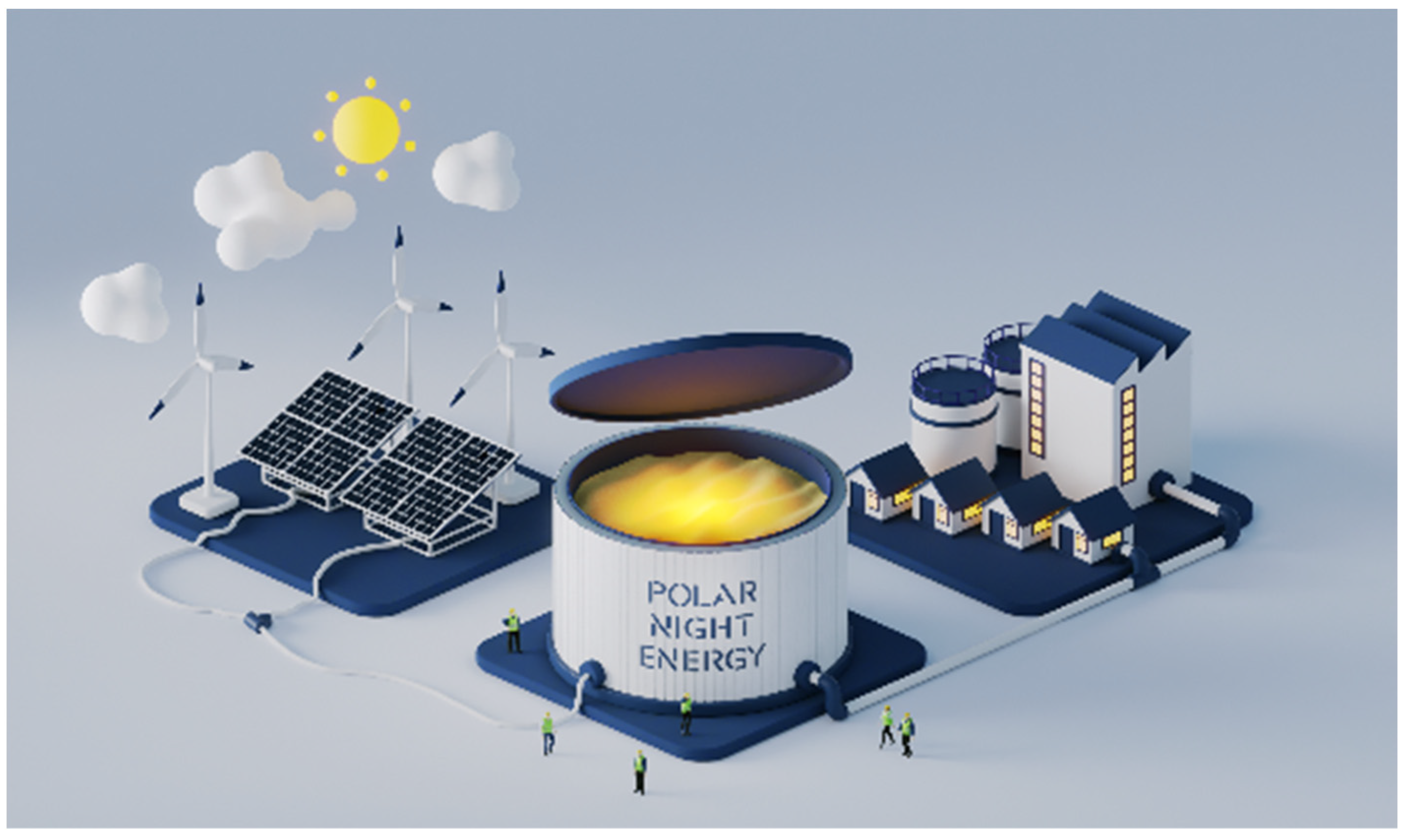
The current geopolitical situation (Russia’s suspension of energy supplies to Finland, which was a consequence of this country’s declaration of willingness to join NATO) and the above-mentioned geopolitical factors have resulted in Finland taking various innovative initiatives in the energy sector. The project realized in Finland tried to provide citizens with enough heat and light. One of the ideas was to use sand as an energy store. Finland has introduced the world’s first commercial “sand battery”. The installation operates in the city of Kankaanpää, approximately 230 km north-west of Helsinki. Houses, offices, and a public swimming pool are heated there with low-emission thermal energy, stored in a steel container 4 m wide, 7 m high, filled with 100 tons of sand. The advantage of a sand bed is that it is a durable, inexpensive material and it can store heat at a temperature of about 500–600 °C for many months. Figure 2 shows a heat storage facility built in Finland by Polar Night Energy [20,24,25,26,27].
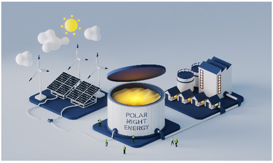
Figure 2.
Polar Night Energy’s sand battery is a large-scale high-temperature thermal energy storage that uses sand or sand-like materials as its storage medium. It stores energy in sand as heat. It has three main purposes: to store excess wind and solar energy; to balance the electrical grid, and to produce heat and power without burning. [Illustration by Simo Heikkinen/Polar Night Energy].
When electricity is cheap or over-produced, the sand is heated using appropriate heaters. In the summer, these heaters are powered by energy from renewable sources, such as photovoltaic panels. Thanks to this, the solar energy collected in summer can be used to heat houses in the winter. The stored heat can also be used for high-temperature industrial processes. The heat storage has a heating power of 100 kW and energy capacity of 8 MWh [28,29,30].
The Finnish company Power Night Energy is not the only one interested in using sand as a heat storage material. Currently, the Italian company Magaldi Green Energy has the largest number of patents related to sand batteries. The company’s solutions include both short- and long-term heat storage systems with sand bed fluidization. Fluidization increases the transfer of thermal energy when charging and discharging storage facilities. However, the Finnish company was the first to build its installation using its own technologies and may become a pioneer in the future in this segment of the energy market [31,32].
The undoubted advantage of the new Power Night Energy solution is its small carbon footprint. Greenhouse gas emissions are limited to the construction phase. The operation of a sand heat storage facility itself exposes the environment to negligible CO2 emissions—provided that the stored heat comes from renewable sources. Sand storage is available for sale to large entities, such as energy and industrial companies or operators of residential and commercial buildings. There are no sand heat accumulators for individual use yet. The price for building 1 kWh of heat capacity reaches EUR 10 [33].
There are the following advantages of sand heat accumulators:
- High heat capacity compared to, e.g., water; sand can be heated to temperatures well above the boiling point of water. Sand-based heat storage facilities can store several times more energy than water storage facilities of the same volume. This saves space and facilitates versatile use in many industrial processes;
- Fuel versatility—heat storage is not sensitive to the size of sand grains.
Another example of the use of sand, water, and carbon dioxide is the solution from Echogen. This solution includes two tanks. One is filled with hot sand and the other is a cold tank filled with cold water or ice. Using an electrically powered heat pump, thermal energy is stored in the sand. When energy is needed, the heat from the sand travels through a heat engine to generate electricity. The Echogen energy storage project is distinguished by the use of supercritical carbon dioxide, which serves in this technology as a heat carrier or as the so-called working fluid [34,35].
Surplus electricity from renewable energy sources is used at the US National Renewable Energy Laboratory (NREL) for testing the heat storage using the silica sand. The heat storage facility, with a maximum capacity of 26,000 MWh, is in the final phase of testing there. The sand in this storage facility can be heated to a temperature of 1200 °C. During the energy demand, heat is used to heat and pressurize the working gas used to drive the turbines and rotate the generator. Using a heat exchanger, this energy can also be used to heat buildings, providing an alternative to heating based on coal or natural gas [28].
2. Concept of Sand Heat Storage in the Closed Mine Workings
2.1. Assumptions for a New Solution with the Technical Data
Based on global experience and adapting to global trends, the authors decided to develop a concept of using piston heat storage facilities in a roadway of liquidated hard coal mines. This idea allows for the revitalization of post-mining areas and their transformation into an energy complex providing the local community with access to cheap and clean heat energy, which can be used to heat houses, housing estates, and public buildings in the selected areas. The advantages of underground storage locations include saving space in densely populated areas, such as Silesia and constant thermal conditions surrounding the storage facility all year round. Constant temperature is beneficial from the point of view of the thermal insulation of the storage facility (on the surface in winter, when there are severe frosts, different insulation is required compared to the summertime to maintain the assumed parameters).
Within the developed concept, three variants of heat storage were prepared. It was assumed that clean sand would be used for storing the thermal energy, which would be heated to a temperature of 500–600 °C. Due to high temperatures, a gas was selected as the working medium, e.g., CO2 or helium. The assumed variants are as follows:
- Variant 1—heat storage with a sand container:
- ○
- assumed heat storage volume: 100 m3;
- ○
- assumed heat storage power: 100 kW;
- ○
- assumed heat storage heat capacity (at temp. 500 °C): 11.37 MWh.
- Variant 2—heat storage in a blind roadway:
- ○
- assumed heat storage volume: 1070 m3;
- ○
- assumed heat storage power depending on fluid flowrate >100 kW;
- ○
- assumed heat storage heat capacity (at temp. 500 °C): 100 MWh.
- Variant 3—heat storage demonstrator:
- ○
- assumed heat storage volume: 25 m3;
- ○
- assumed heat storage power: 50 kW;
- ○
- assumed heat storage heat capacity (at temp. 500 °C): 2.27 MWh.
2.2. Selection of Insulating Materials
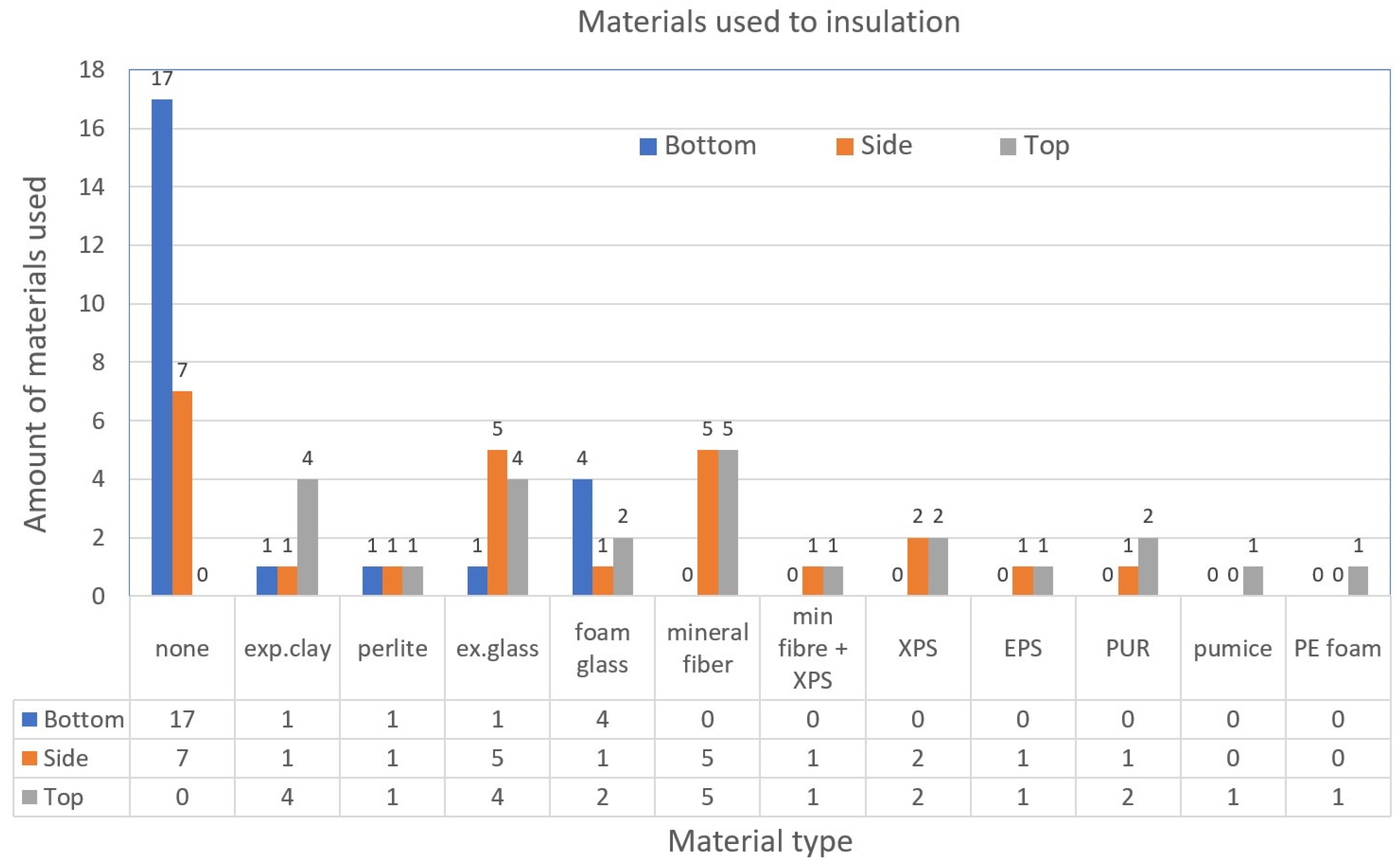
One of the problems to be solved is the use of an insulating material with appropriately high-temperature parameters while maintaining low thermal conductivity. Following the reference [29], industrial (conventional) insulation materials include mineral fibers, extruded polystyrene foam (XPS), expanded polystyrene foam (EPS), polyethylene foam (PE), polyurethane foam (PUR) and polyisocyanurate (PIR) foam. Figure 3 shows that the mentioned materials constitute over 50% of the materials used to insulate the side and upper walls. PUR/PIR foams are useful for both side and top wall insulation, while mineral fibers can only be used as the upper parts of heat storage. Due to insufficient stress resistance, such conventional materials cannot be considered for use as insulation for the lower part of a storage facility.
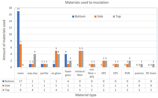
Figure 3.
Amount of materials used for: bottom, side, and top insulation. In the lower part, mainly foam glass is used, while the side walls are mainly insulated with conventional mineral wool and expanded glass. The greatest diversity occurs in upper insulation, where natural, conventional, and recycled materials are used. (where: exp.clay—expanded clay; ex.glass—expanded glass; min.fiber—mineral fiber; XPS—extruded polystyrene foam; EPS—expanded polystyrene foam; PUR—polyurethane foam; PE Foam—polyethylene foam).
The main disadvantage of conventional insulating materials is that they have non-uniform thermal behavior. For mineral fibers, the thermal conductivity decreases significantly with temperature 40–90 °C [1]. Moreover, if groundwater (or rainwater) penetrates the insulation layer in the case of leaks, the thermal conductivity of such insulation increases significantly [36]. Wrapping of XPS or PUR sheets in a type of waterproofing membranes can be used, but this is a very expensive solution.
Natural materials used as thermal insulators include pumice, expanded perlite, and expanded clay. The first two are fine-grained volcanic materials. Expanded perlite has the best thermal properties but is unsuitable due to its low pressure resistance [37]. The advantage of expanded clay is its low density. The advantages of natural materials are low costs and a beneficial impact on the environment.
It is also possible to use recycled material such as foam glass in the form of sheets or granules (Figure 4) or expanded glass granules (Figure 5). Foamed cellular glass can be used as a material for bottom insulation, while expanded glass granules are often used for side and top wall insulation. In addition to attractive thermal insulation properties, these materials also demonstrate good mechanical resistance [38]. Among the recycled materials, glass granulate has the lowest thermal conductivity [37]. In addition, all recycling materials are water-resistant and can be easily dried. Therefore, glass granulate was selected as a moisture-resistant material that can be used on the outside of the storage facility side walls. Foam glass is installed in the form of 15 cm thick boards at the bottom and expanded glass granules—in 0.5 m thick geotextile bags. It is reported in the literature that foam glass gravel, expanded glass granules, and expanded clay are considered particularly suitable for insulation.
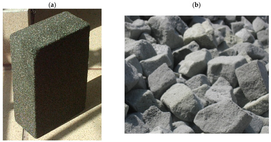
Figure 4.
Foam glass in the form of (a) sheets [39] or (b) granulate [40].
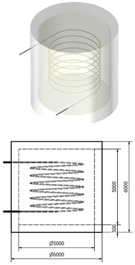
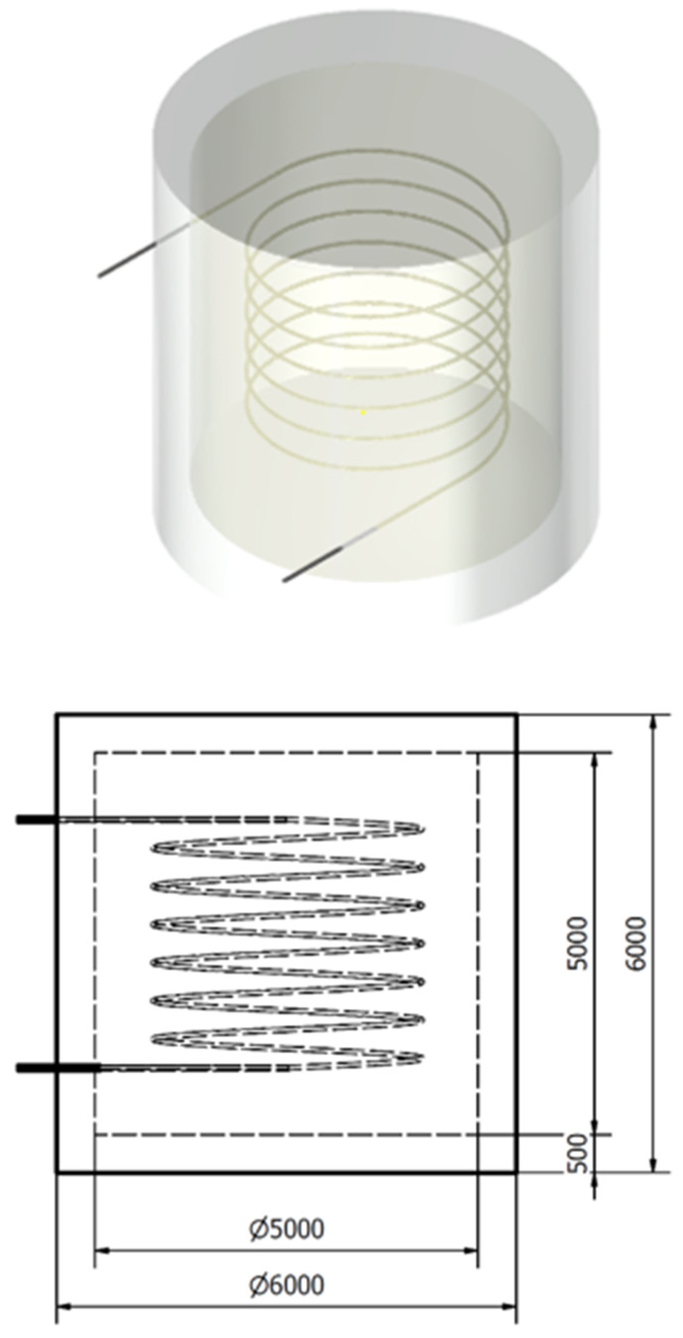
Figure 5.
Concept of the heat storage of volume 100 m3 of constant walls thickness 500 mm [own solution].
Currently, a cubic meter of foamed glass costs on average PLN 270. The same volume of Styrofoam costs PLN 290, and extruded polystyrene costs PLN 480. Use of foam glass is therefore also economically justified. Granules of 4–8 mm are packed in Bigbags 1.5 m3.
2.3. Method for Fixation of Thermal Insulation
Proper construction of thermal insulation layers is a challenge from the point of view of physics and thermodynamics of heat storage. At the same time, heat conduction and diffusion of water vapor from the inside to the outside and the penetration of water from the outside to the inside should be avoided. Thermal insulation materials are available in the form of boards or as loose material (Figure 4). The advantage of boards is that they do not require the installation of complex frames or textile bags to permanently hold the insulating material. However, the disadvantage is that the boards always require additional waterproofing. Therefore, for simple installations, bulk materials are preferred because they can be directly filled into prefabricated geotextile bags and achieve watertight thermal insulation in one operation. In this way, a thermal insulation structure with a volume of 25 m3 can be installed in a short time. Additionally, air will be sucked off at the end of the work. Tight vacuum bags with granules will improve stability through compaction and negative pressure. At the same time, the material is protected against moisture. In addition, long-term monitoring is possible via vacuum control. Thermal bridges should be avoided throughout the heat storage by the appropriate installation of connecting pipes.
Since temperature distribution inside the heat storage, and consequently also the heat loss, is not uniform but increases from the base to the top, the insulation thickness of the side walls can be increased according to the height. The thickness of the side wall insulation increases. At the base, it will be 300 mm and at the top of the heat storage a maximum of 700 mm. This method of arranging the insulation will reduce costs without losing efficiency, compared to walls 700 mm thick. For similar costs, in this solution, the 500 mm wall thickness would have to be maintained along entire length (Figure 5).
2.4. Installation of Insulating Materials in the Suggested Energy Storage Variants
- Variant 1. Concept of the heat storage of volume 100 m3
Estimated cost for purchasing the components for heat storage of volume 100 m3 for constant thickness of walls 500 mm is given in Table 1.

Table 1.
Cost for purchasing the components for heat storage of volume 100 m3 for constant thickness of walls 500 mm.
In a volume of approximately 100 m3 of sand at a temperature of 500–600 °C, approximately 9.1 MWh of heat can be stored, a heating power of up to 100 kW is assumed.
- Variant 2. Concept of heat storage in a mine blind roadway
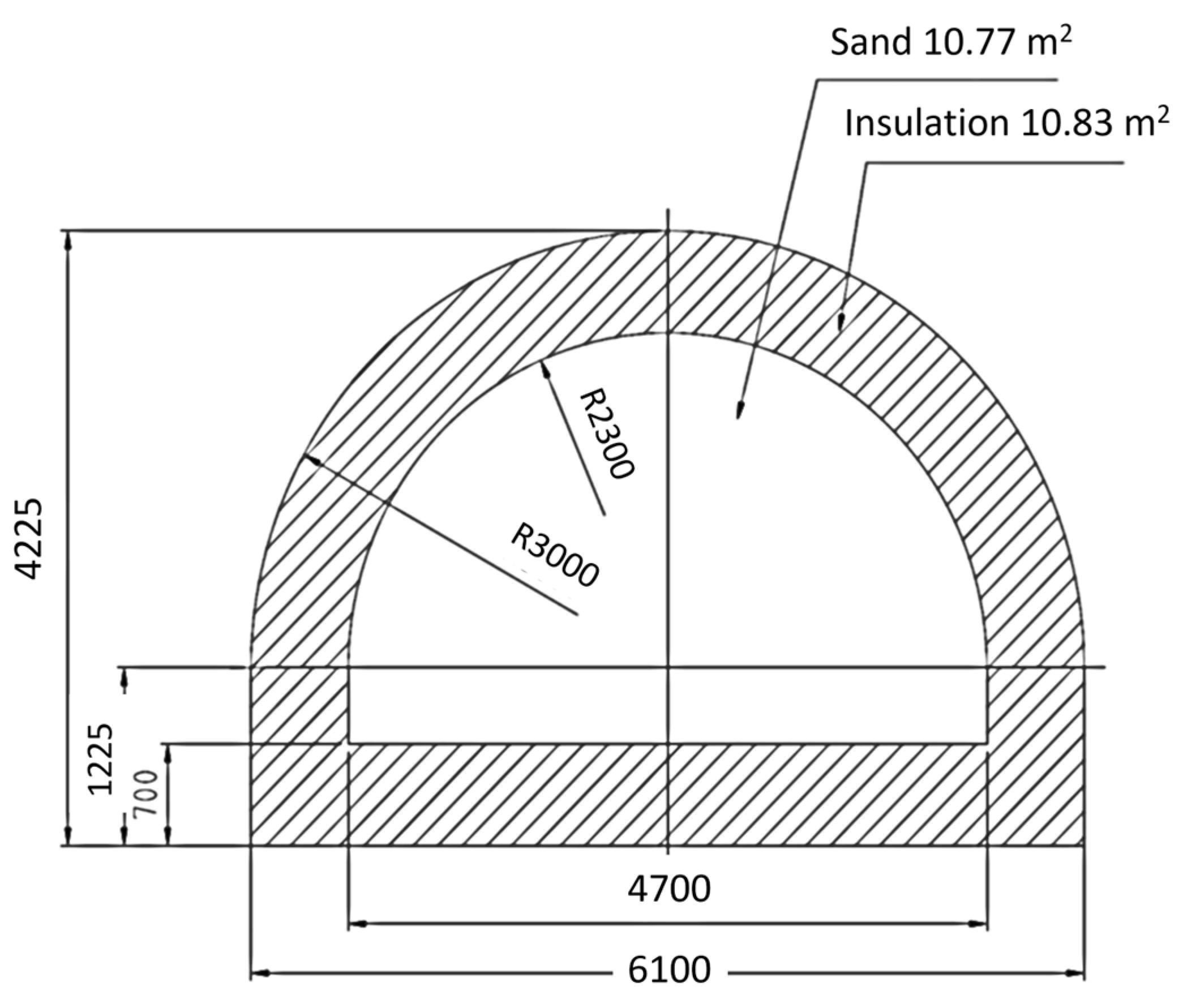
When developing the heat storage concept in variant 2, the most popular ŁP 12 yielding arch roof support, the V29 section was taken into account. This support has a cross-section surface area of 21.9 m2 (Figure 6). Length of the blind face was assumed to be 100 m, the insulation thickness was assumed to be 700 mm, and glass granules were the insulation material. The active cross-section area of the heat storage was calculated to be 10.83 m2 (Figure 7).
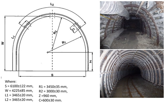
Figure 6.
Characteristic dimensions of the ŁP yielding roadway roof support as well as examples of mine corridors using such support [own source].

Figure 7.
Assumptions relating to the variant based on the ŁP 12 yielding roadway roof support [own source].
The estimated costs of purchasing the heat storage components built in a blind roadway with a constant thickness of insulating walls of 700 mm over a length of 100 m are presented in Table 2.
Table 2.
Costs of purchasing the heat storage components built in a blind roadway with a constant thickness of insulating walls of 700 mm.
In a volume of approx. 1070 m3 of sand at a temperature of about 500 °C, about 100 MWh of heat can be stored. The assumed heating power is greater than 100 kW, which depends on the flow rate of the working medium.
3. Proposal of Solutions for Heat Storage Systems Using High-Temperature Sand Storages
- VARIANT 1—using the proper containers in underground mine workings.
Variant 1 is intended for development in roadways remaining in closed mines, but which must be passable, e.g., for crew movement and the maintenance of closed mine workings. The storage facility in this variant can also be built in unused assembly rooms or in repair chambers.
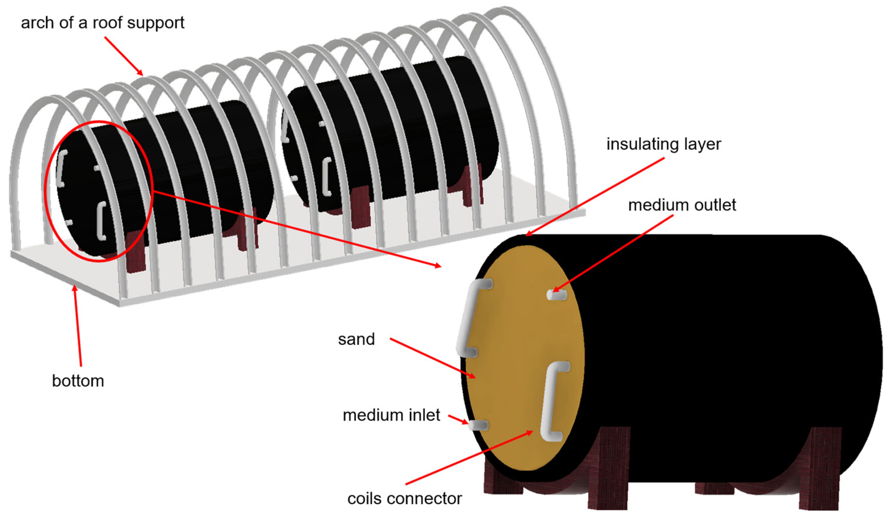
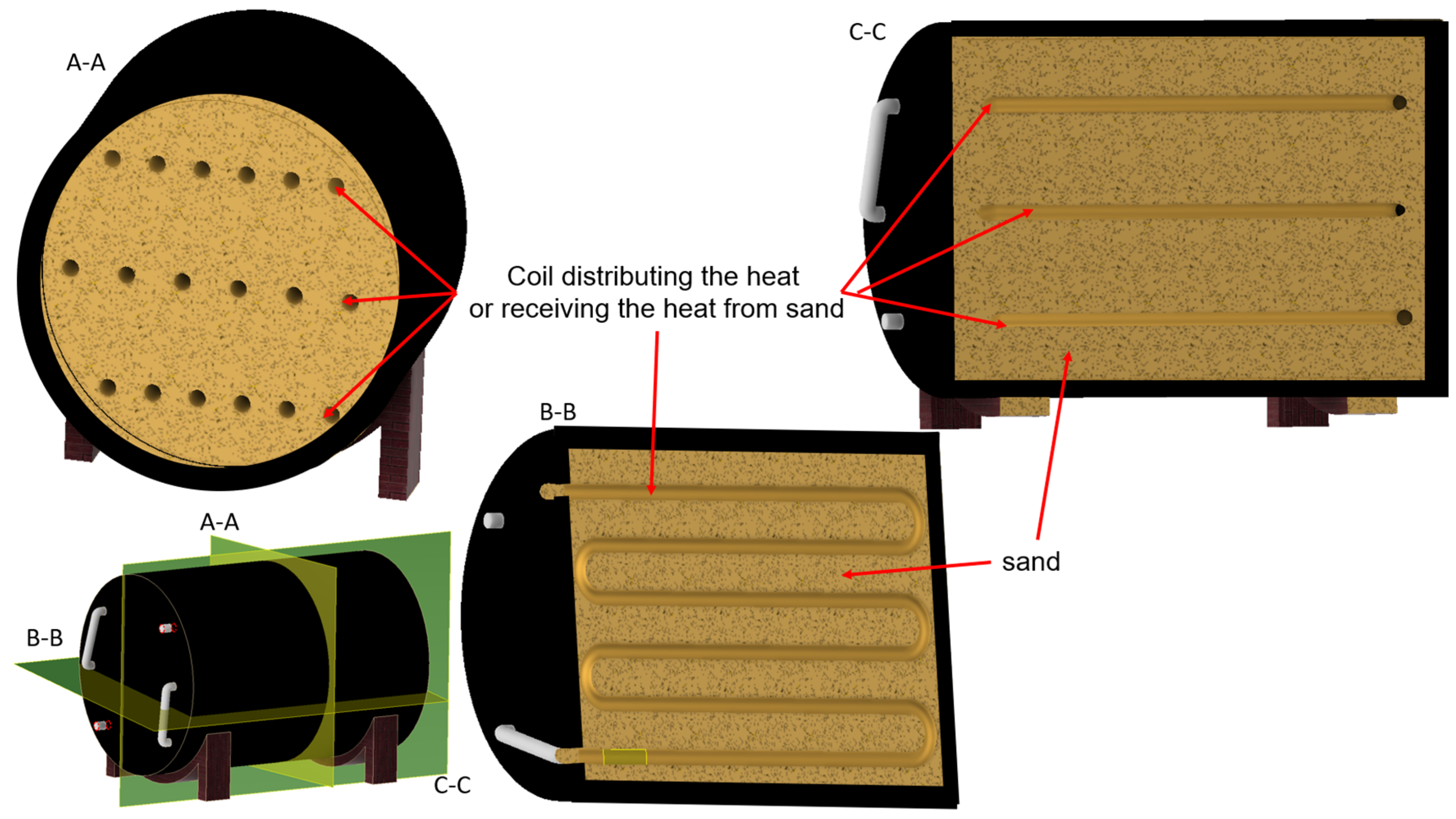
In this variant, reservoirs such as cisterns can be used to build a heat storage facility, or a storage facility can be installed in a form of a steel pipe with a diameter adapted to the size of the workings keeping the required movement gaps. Such a reservoir is to be covered with a layer of thermal insulation to protect against heat loss during its storage. Then, the tank will be filled with sand, in which coils made of material with good thermal conductivity will be placed during the assembly stage. After filling the reservoir with sand and placing the coils, the heat storage will be tightly closed. Only the connections to the coils (inlet and outlet of the working medium) will be led outside.
In Figure 8, Variant 1 in a mine roadway is presented.

Figure 8.
Variant 1 of the sand heat storage in a mine roadway [own source].
In Figure 9, a cross-section of the heat storage in Variant 1 is presented.

Figure 9.
Cross-section of the heat storage in Variant 1 [own source].
Once the heat storage is built, the process of storing thermal energy by circulating the heated working medium can start. The heating procedure and heat energy release will be described collectively in relation to all three variants.
- VARIANT 2—construction of heat storage in roadways of the liquidated mines
Variant 2 is intended for construction in the blind workings of closed mines. Such workings may include old roadway faces or sections of roadways, which will be permanently dammed, closing access to the remaining roadways. In Variant 2, it is also possible to build a heat storage facility in unused and liquidated assembly rooms and repair chambers, in underground spare part warehouses, etc.
In Variant 2, a layer of thermal insulation will be applied to all surfaces of the side walls, the floor, and the roof of the roadway. Then, the free space will gradually be filled with sand and closed. At separations assumed in the design, coils made of materials with good thermal conductivity will be placed on the sand. Each of these layers will be covered with another layer of sand and another part of the roadway will be closed. After the roadway is completely filled, the structure will be tightly closed and thermally insulated. Only the coil connections will remain outside (inlet and outlet of the working medium). The concept of Variant 2 of the heat storage facility is presented in Figure 10.
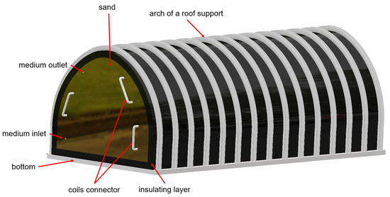
Figure 10.
Concept of Variant 2 of the sand heat storage [own source].
In Figure 11, cross-sections showing the concept of heat storage of Variant 2 are presented.
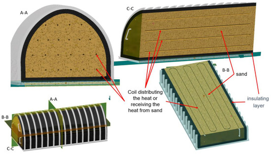
Figure 11.
Cross-sections showing the concept of heat storage Variant 2 [own source].
Once the heat storage is constructed, the process of storing thermal energy can be started by circulating the heated working medium. The procedure for heating and releasing thermal energy will be described collectively in relation to all three variants.
- VARIANT 3—demonstrator
Option 3 of the heat storage is a form of demonstrator. It can be constructed in any place, e.g., in the basement, in the area in front of the building, etc. This variant is constructed similarly to Variant 1, but it is scaled. Variant 3 can be constructed for demonstration purposes from a boiler or a piece of thermally insulated steel pipe of any diameter. Similarly to Variant 1, it will be filled with sand in which coils distributing and receiving thermal energy will be placed. After completing the thermal insulation and filling the heat storage with sand, you can connect the working medium to the coils and start operating the heat storage.
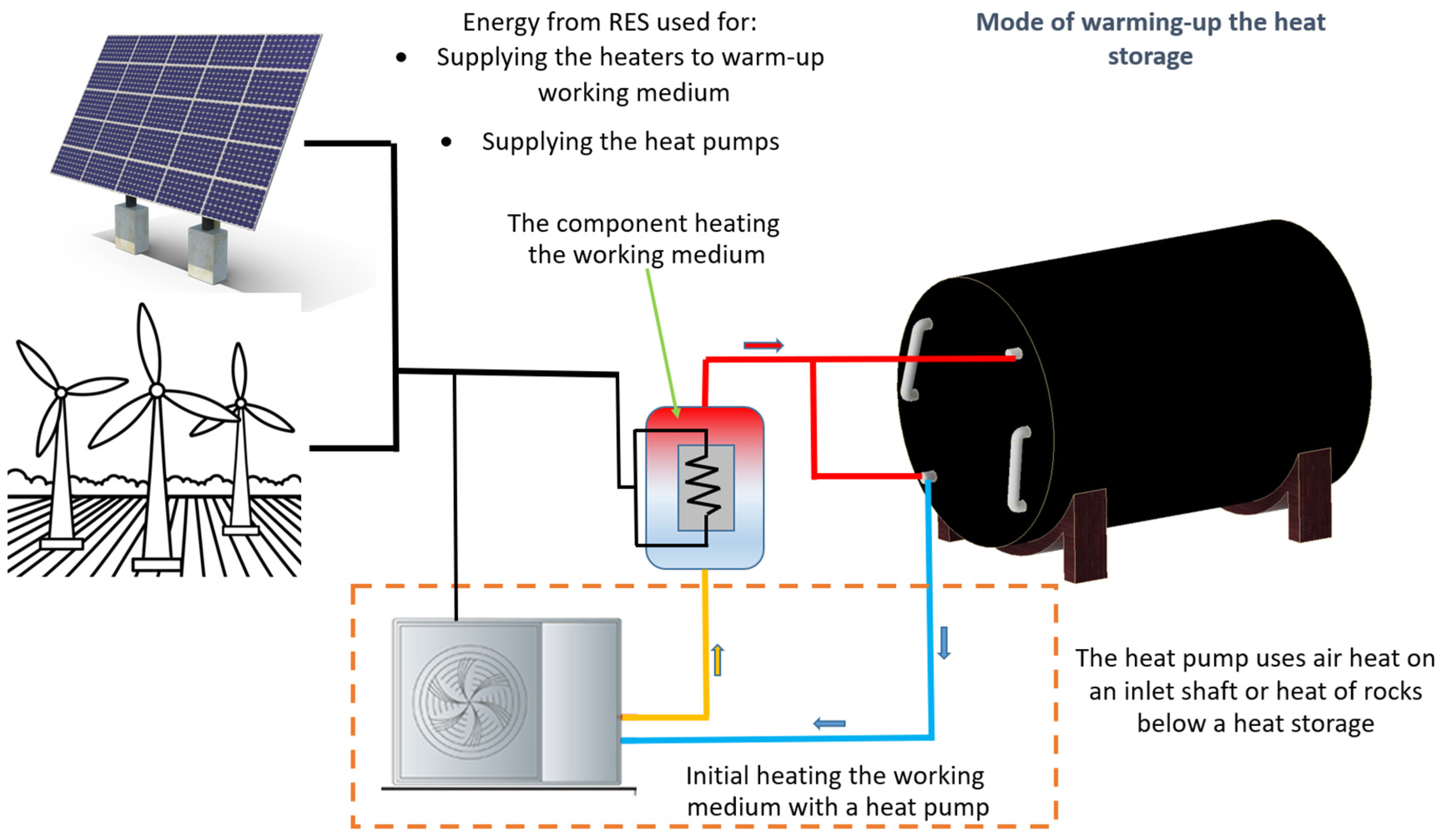
In Figure 12, a diagram of heating the sand heat storage is presented.
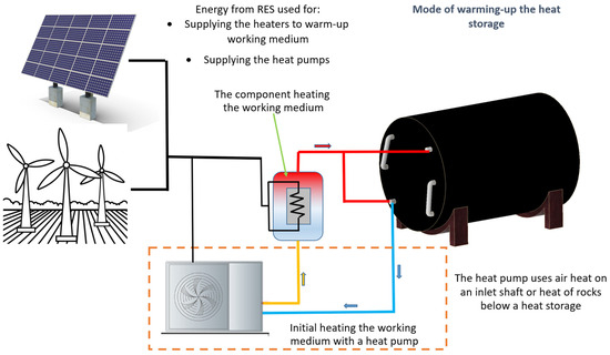
Figure 12.
Diagram of heating the sand heat storage [own source].
Another innovation is the idea of using a heat pump, which would be installed in such a way as to use thermal energy of rocks in the lower layers of the mine (if available). The heat pump can also be based on the air heat at the level where the heat storage is installed. The purpose of using a heat pump would be to preheat the working medium, which would result in an easier and faster achievement of a higher temperature of this medium as a result of the operation of the electric heater. Such a solution would also be an ecological solution.
An alternative to using a heat pump may be the use of a heat exchanger using waste heat from industrial plants located near the location of the proposed heat storage facility. The heating scheme is presented below (Figure 13).
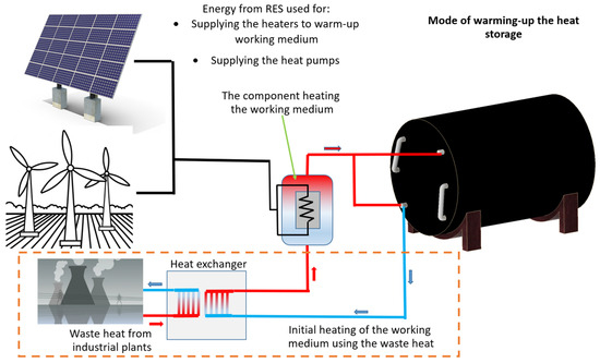
Figure 13.
Diagram of heating the sand heat storage—version using the waste heat [own source].
A necessary condition for using the presented solution is the presence of an industrial plant producing a significant amount of waste heat in the close vicinity of the location of the heat storage facility.
After collecting the required amount of heat, the energy storage can be used for:
- heating residential estates, e.g., by connecting to the municipal heating system;
- heating private estates—single-family houses;
- heating public places such as nurseries, kindergartens, schools, offices, hospitals, etc.;
- heating of domestic hot water;
- heating the road infrastructure—instead of snow removal and chemical agents used on roads when they are icy, by turning the heating on, the snow and ice will melt (aspect of financial savings for the city/district and pro-ecological aspect—no chemicals, no emissions during the production of brines, no emissions during spreading salt by snow plows).
The heat storage discharge mode is shown in Figure 14.
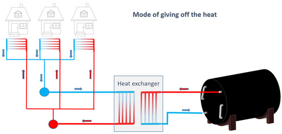
Figure 14.
Mode of discharging the heat storage [own source].
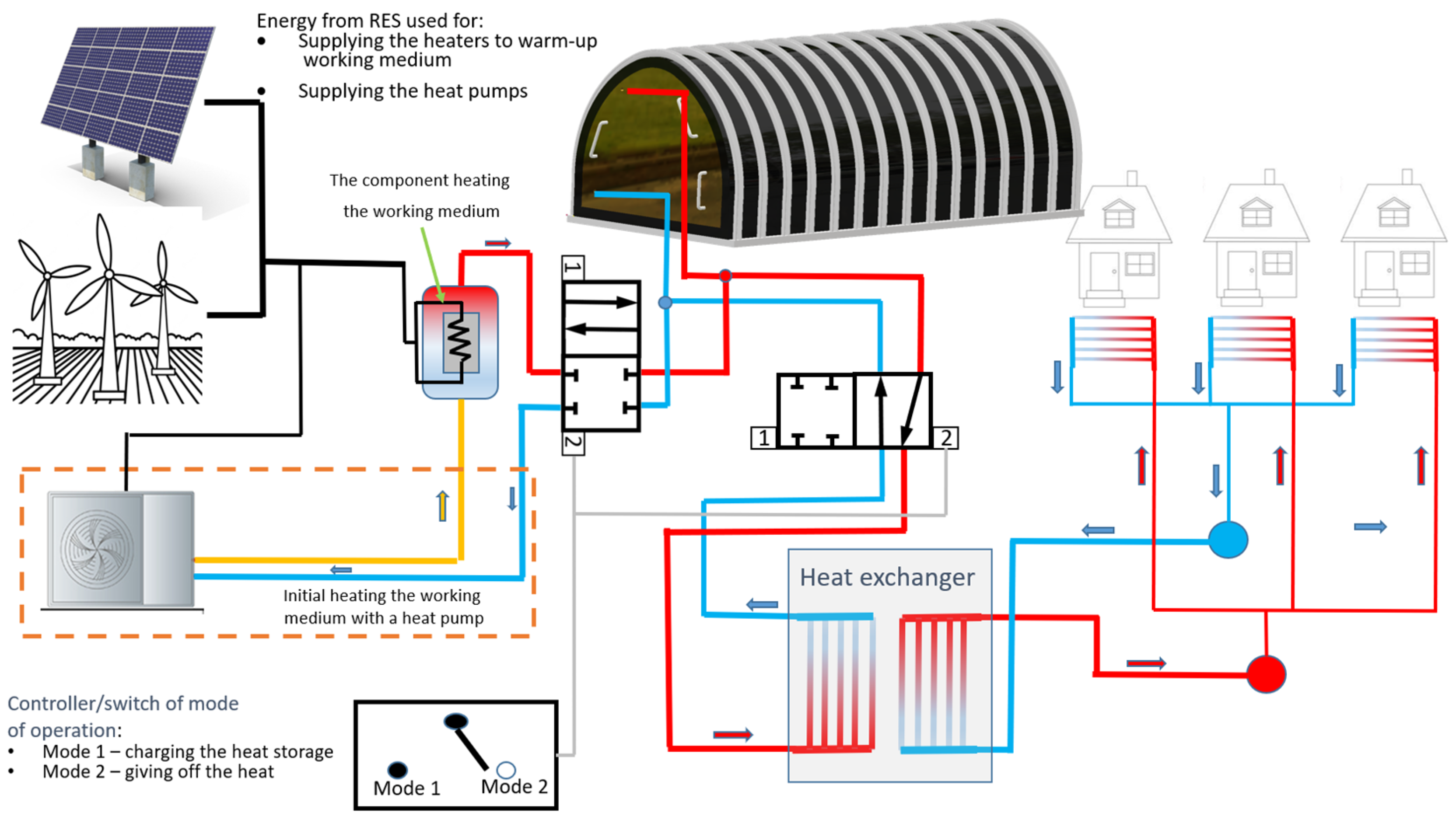
The capability of the proposed heat storage facility depends on the size of the storage facility itself (number of reservoirs, amount of sand, length of mine roadways intended for this purpose, etc.), as well as the possibility of charging the storage facility (required number of photovoltaic panels, wind power plants, waste heat, etc.). A diagram of the system based on Variant 2 of the heat storage facility is shown in Figure 15.
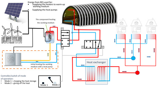
Figure 15.
Diagram of the system based on Variant 2 of the heat storage facility [own source].
4. Discussion
The solution presented in this article, consisting of storing heat in high-temperature sand storage tanks located in underground mining excavations, has many advantages and can help reduce problems related to power balancing in power grids and also improve air quality and reduce greenhouse gas emissions. Large post-mining areas located in the vicinity of the centers of Silesian cities, or in close proximity to residential estates after the mine is closed down, are an excellent area for implementing such an investment. On the one hand, post-industrial areas will be used effectively, on the other hand, we can improve the quality of life of residents. This improvement can occur in several aspects. The first is the already mentioned improvement in air quality resulting from the reduction in the use of solid fuels for heating apartments and public buildings. The second aspect is the economic aspect; by storing thermal energy from renewable energy sources, residents can have long-term access to clean and relatively cheap energy for heating their apartments and houses in winter heating periods. Another benefit, this time for the natural environment, is reduced CO2 emissions resulting from the reduction in or elimination of solid fuel combustion, but also related to the cessation of the mine operation process and coal extraction. Another aspect is the possibility of obtaining waste heat from nearby industrial plants, which may have a positive impact on their economic results. However, it should be noted that the use of the presented technology is also associated with certain limitations and its implementation may encounter certain problems. The basic limitation that may be encountered in the case of the desire to implement the above solution is the issue of land-ownership and the development plan. When planning such an investment, it is advisable for the land to belong to local government authorities who intend to introduce an ecological heating system using the presented technology. Development plans for the selected post-mining area must also be submitted to the appropriate institutions developing the plan for the liquidation and reclamation of mining plants in advance. Otherwise, changing the plan and obtaining the necessary consents may be associated with a long and tedious formal procedure that does not guarantee success. Another aspect is the need to maintain underground workings (or at least a part of them) and the shaft. In the case of mining plants, where for safety reasons, e.g., pumping water, it is planned to maintain a certain number of underground corridors, the matter is relatively easier and the costs of maintaining the infrastructure are planned. The matter is much more difficult in the case of the lack of plans to maintain underground workings and the possibility of reaching these corridors. It is estimated that the costs of maintaining the workings will constitute the second, after the investment costs, component of the general costs. Of course, the investment costs will not be small, however, in this aspect the investor can apply for various types of targeted subsidies. To sum up, the technology of storing heat in high-temperature underground heat storage tanks proposed by the authors is undoubtedly a new and unprecedented way of using former mine workings. It can be an alternative to currently used heating methods. However, its implementation and implementation still requires further work related to adapting the mine and municipal infrastructure to use the new heating method.
5. Conclusions
The presented concepts are described in terms of possible applications. Basic technical assumptions were indicated, such as the method of construction in the excavation and proposals for insulating materials and the method of their installation. Another modern approach is the use of a heat pump, which preheats the working medium while loading the warehouse. The heat pump uses the difference in air temperatures between the surface and the level of the workings from which the air is taken. If the heat storage facility presented in the concept is not located on the premises of former mining plants, waste heat from nearby industrial plants, e.g., from a power plant or steelworks, can be used to preheat the working medium. For this purpose, the heat pump is replaced by a heat exchanger. The geopolitical situation and the decarbonization policy of the European Union favor the development of renewable energy systems and the diversification of energy sources. However, the main disadvantage of renewable energy sources is the production of electricity in precisely defined weather conditions, such as required wind speed at wind farms or required sunlight at photovoltaic farms. The variability in weather conditions results in large surpluses of energy production in certain periods of the year, with insufficient production in other periods. The only solution to ensure the stability of energy supplies from RES is to build energy storage facilities in which excess energy produced by a given RES source in favorable conditions will be “stored”, which will then be used when there is an increased energy demand. One way to store energy is to store thermal energy in the summer for use in winter, to heat both residential and residential buildings and public utilities. Presented concepts for the construction of heat storage facilities in underground mine workings are in line with the related development trend with the diversification of energy sources and the development of renewable energy sources. The volumes of post-mining roadways are large enough to build thermal energy storage facilities that will cover the heat demand of a significant part of society. However, the condition is the construction of appropriate infrastructure supplying thermal energy to storage facilities, i.e., appropriate photovoltaic farms, wind farms, installations collecting waste heat from industrial plants, etc. The combination of these investments will not only enable access to cheap thermal energy in winter but will significantly improve air quality and environmental cleanliness. This will happen as a result of reducing harmful emissions from the combustion of solid and liquid fuels for heating purposes. Carbon dioxide emissions into the atmosphere will also be significantly reduced.
This article presents both the idea and the concept for methods for installing a high-temperature heat storage in unused mine workings. As presented in the discussion section, a number of development works and those related to obtaining appropriate permits must be carried out before the implementation of the proposed solution. The authors foresee the following tasks as further directions of the development work:
- One of the directions of the research work will be the optimization of the thickness of the insulation layer and the differentiation in its thickness and the variability in materials in relation to the height in order to optimize costs while maintaining the required effectiveness.
- Another aspect will be the performance of virtual prototyping tasks. As part of this work, a numerical model will be developed, which will be used to perform numerical analyses using CFD methods. This work will aim to verify and optimize the operation of heat exchangers, the effectiveness of the insulation layer, and the selection of the target temperature of the heat storage.
- Another direction of the application of numerical analyses will be to optimize the method of laying out the coils in the heat storage. This is important from the point of view of the even level of heating of the sand in the warehouse and avoiding the occurrence of “dead zones” in which it is difficult to achieve the assumed temperature or in which there may be a problem with heat reception.
- Another important issue is the possibility of considering the use of alternative media circulating in coils in the heat warehouse.
- Before the final implementation, it is necessary to build a prototype that takes into account the above-mentioned problematic aspects both in a purely technical and organizational sense. Further activities will be planned towards the construction of a demonstrator in conditions close to real ones.
Author Contributions
Conceptualization, K.S. and D.M.; methodology, P.M.; validation, K.S. and D.M.; formal analysis, D.K.; investigation, D.M. and K.S.; resources, D.K.; data curation, K.S.; writing—original draft preparation, D.M.; writing—review and editing, D.K.; visualization, K.S.; supervision, D.M.; project administration, P.M.; funding acquisition, D.K. All authors have read and agreed to the published version of the manuscript.
Funding
This research received no external funding.
Data Availability Statement
Data are contained within the article.
Conflicts of Interest
The authors declare no conflicts of interest.
References
- Website. Available online: https://web.archive.org/web/20240226074456/www.iftechnology.com/aquifer-thermal-energy-storage/ (accessed on 10 July 2024).
- Conference Presentation. Available online: https://docplayer.pl/5441174-Magazynowanie-energii-na-potrzeby-ogrzewania-chlodzenia-przyklady-rozwiazan.html (accessed on 12 July 2024).
- Janas, S. The concept of a household low-speed kinetic energy storage. Min. Mach. 2023, 41, 37–47. [Google Scholar]
- Malec, M.; Stańczak, L.; Ricketts, B. Just transition of post mining areas—Technical, economic, environmental and social aspects. Min. Mach. 2023, 41, 11–24. [Google Scholar]
- Website. Available online: https://www.macobo-stabo.be/diensten/gebouwtechnieken/show/85 (accessed on 12 July 2024).
- Ermiş, K.; Findik, F. Thermal energy storage. Sustain. Eng. Innov. 2020, 2, 66–88. [Google Scholar] [CrossRef]
- Website. Available online: https://www.rynekelektryczny.pl/moc-zainstalowana-fotowoltaiki-w-polsce/ (accessed on 14 March 2025).
- Website. Available online: https://ieo.pl/aktualnosci/1684-fotowoltaika-w-polsce-w-2023-i-2024-nowe-moce-i-nowe-wyzwania (accessed on 14 March 2025).
- Website. Available online: https://www.oze.pl/blog/30-gw-w-polskiej-fotowoltaice-do-2026-roku-to-mozliwe (accessed on 14 March 2025).
- Pijarski, P.; Saigustia, C.; Kacejko, P.; Bena, L.; Belowski, A. The impact of renewable energy sources on the overload of high voltage lines—Power flow tracking versus direct current method. Arch. Electr. Eng. 2024, 73, 519–541. [Google Scholar] [CrossRef]
- Website. Available online: https://zielonagospodarka.pl/jak-wyglada-rynek-fotowoltaiki-w-polsce-w-2024-roku-17097 (accessed on 14 March 2025).
- Chavan, S.; Rudrapati, R.; Manickam, S. A comprehensive review on current advances of thermal energy storage and its applications. Alex. Eng. J. 2022, 61, 5455–5463. [Google Scholar] [CrossRef]
- White, M.T.; Sayma, A.I. A new method to identify the optimal temperature of latent-heat thermal-energy storage systems for power generation from waste heat. Int. J. Heat Mass Transf. 2020, 149, 119111. [Google Scholar] [CrossRef]
- Sarbu, I.; Sebarchievici, C. Solar Heating and Cooling: Fundamentals, Experiments and Applications; Oxford Elselvier: Oxford, UK, 2016; ISBN 978-0-12-811662-3. [Google Scholar]
- Dinçer, I.; Rosen, M.A. Thermal Energy Storage Systems and Applications; John Wiley & Sons: Toronto, ON, Canada, 2011; ISBN 9781119713166. [Google Scholar]
- Heat Storage—Types of Storage. Heat Storage is a Process That Poses Special Challenges to Physicists, Chemists and Designers. Available online: https://www.cire.pl/artykuly/materialy-problemowe/119630-magazynowanie-ciepla-rodzaje-magazynow (accessed on 12 July 2024).
- Million Cubic Meter 90GWh Thermal Storage Project in Finland Could Begin Construction Next Year. Available online: https://www.energy-storage.news/million-cubic-metre-90gwh-thermal-storage-project-in-finland-could-begin-construction-next-year (accessed on 12 July 2024).
- Mania, T.; Kawa, J. Inżynieria Instalacji Magazynowania Energii Ciepła; Mroziński, A., Ed.; Grafpol Agnieszka Blicharz-Krupińska: Bydgoszcz, Poland, 2016. [Google Scholar]
- Jastrzębski, P.; Saługa, P.W. Innowacyjne metody magazynowania ciepła. Zesz. Naukowe. Inst. Gospod. Surowcami Miner. Energią 2018, 105, 225–232. [Google Scholar]
- World’s First Sand Battery the Answer to Energy Challenges? Available online: https://dzienniknaukowy.pl/nowe-technologie/pierwsza-na-swiecie-bateria-piaskowa-odpowiedzia-na-wyzwania-energetyczne (accessed on 12 July 2024).
- Alva, G.; Lin, Y.; Fang, G. An overview of thermal energy storage systems. Energy 2018, 144, 341–378. [Google Scholar]
- Ochs, F.; Heidemann, W.; Müller-Steinhagen, H. Langzeit-Wärmespeicher für Solare Unterstützte Nahwärmesysteme; 2. Internationale Speicherkonferenz Erneuerbare Energien-IRES II: Bonn, Germany, 2007. [Google Scholar]
- Ochs, F.; Müller-Steinhagen, H. Abschlussbericht zum Vorhaben Weiterentwicklung der Erdbecken-Wärmespeichertechnologie FKZ 0329607 E. Institut für Thermodynamik und Wärmetechnik (ITW), Universität Stuttgart, Stuttgart: S.n. 2008. Available online: https://www.igte.uni-stuttgart.de/veroeffentlichungen/publikationen/publikationen_08-05.pdf (accessed on 15 July 2024).
- Website. Available online: https://gazetawroclawska.pl/magazyn-ciepla-w-piasku-w-soli-dlaczego-nie/ar/c15-16885841 (accessed on 15 July 2024).
- Kalidasan, B.; Pandey, A.K.; Shahabuddin, S.; Samykano, M.; Thirugnanasambandam, M.; Saidur, R. Phase change materials integrated solar thermal energy systems: Global trends and current practices in experimental approaches. J. Energy Storage 2020, 27, 101118. [Google Scholar] [CrossRef]
- Sand Battery. Available online: https://polarnightenergy.fi/sand-battery (accessed on 15 July 2024).
- The World’s First “Sand Battery” Goes Live. Available online: https://wired.me/science/worlds-first-sand-battery-finland (accessed on 15 July 2024).
- NREL Options a Modular, Cost-Effective, Build-Anywhere Particle Thermal Energy Storage Technology. Available online: https://www.nrel.gov/news/program/2021/nrel-options-a-modular-cost-effective-build-anywhere-particle-thermal-energy-storage-technology.html (accessed on 15 July 2024).
- Mangold, D. Erfahrungen und Ergebnisse aus der Umsetzung der Bundesforschungsprogramme Solarthermie-2000 und Solarthermie2000plus Input zum EU-Vorhaben Solarge (Solarthermische Großanlagen); Target GmbH: Hannover, Germany, 2006. [Google Scholar]
- Kaczmarczyk, K.; Dobrzaniecki, P. Energy storage using compressed air. Min. Mach. 2023, 41, 25–36. [Google Scholar]
- Finns “Invented the Sand Battery,” or TES Heat Storage, Which Has Been Known for 50 Years. Available online: https://itbiznes.pl/felieton/finowie-wynalezli-piaskowa-baterie-tes/ (accessed on 15 July 2024).
- MAGALDI—Quartz Sand an Energy Store. Available online: https://magazynfotowoltaika.pl/magaldi-piasek-kwarcowy-magazynem-energii/ (accessed on 15 July 2024).
- Sarbu, I.; Sebarchievici, C.A. Comprehensive Review of Thermal Energy Storage. Sustainability 2018, 10, 191. [Google Scholar] [CrossRef]
- Using Ice and Sand for Energy Storage. Available online: https://e-magazyny.pl/magazyny-energii/wykorzystanie-lodu-i-piasku-do-magazynowania-energii/ (accessed on 15 July 2024).
- Sand, Ice and Supercritical CO2: Innovative Long-Duration System Offers ‘Cheapest Energy Storage Yet’. Available online: https://www.rechargenews.com/energy-transition/sand-ice-and-supercritical-co2-innovative-long-duration-system-offers-cheapest-energy-storage-yet-/2-1-1011163 (accessed on 15 July 2024).
- Hua, W.; Lv, X.; Zhang, X.; Ji, Z.; Zhu, J. Research progress of seasonal thermal energy storage technology based on supercooled phase change materials. J. Energy Storage 2023, 67, 107378. [Google Scholar]
- What Are Sand Batteries and Can They Solve the Sustainable Energy Crisis? Available online: https://www.azom.com/article.aspx?ArticleID=21871 (accessed on 15 July 2024).
- Surplus from RES Will Go into the Sand? New Idea for Energy Storage! Available online: https://globenergia.pl/nadwyzki-z-oze-trafia-do-piachu-nowy-pomysl-na-magazynowanie-energii (accessed on 15 July 2024).
- Foam Glass. Available online: https://commons.wikimedia.org/wiki/File:Foamed_glass_block.jpg (accessed on 15 July 2024).
- Granulated Foam Glass. Available online: https://pl.wikipedia.org/wiki/Plik:Szk%C5%82o_spienione_(piankowe).png (accessed on 15 July 2024).


Disclaimer/Publisher’s Note: The statements, opinions and data contained in all publications are solely those of the individual author(s) and contributor(s) and not of MDPI and/or the editor(s). MDPI and/or the editor(s) disclaim responsibility for any injury to people or property resulting from any ideas, methods, instructions or products referred to in the content. |
© 2025 by the authors. Licensee MDPI, Basel, Switzerland. This article is an open access article distributed under the terms and conditions of the Creative Commons Attribution (CC BY) license (https://creativecommons.org/licenses/by/4.0/).