Trade-Off Conceptual Design of a Camber Morphing Flap for the Next Generation Hybrid Electrical Aircraft Across the HERWINGT Project
Abstract
1. Introduction
2. Design Approach and Reference Wing
3. Conceptual Design
3.1. Aerodynamic Assessment
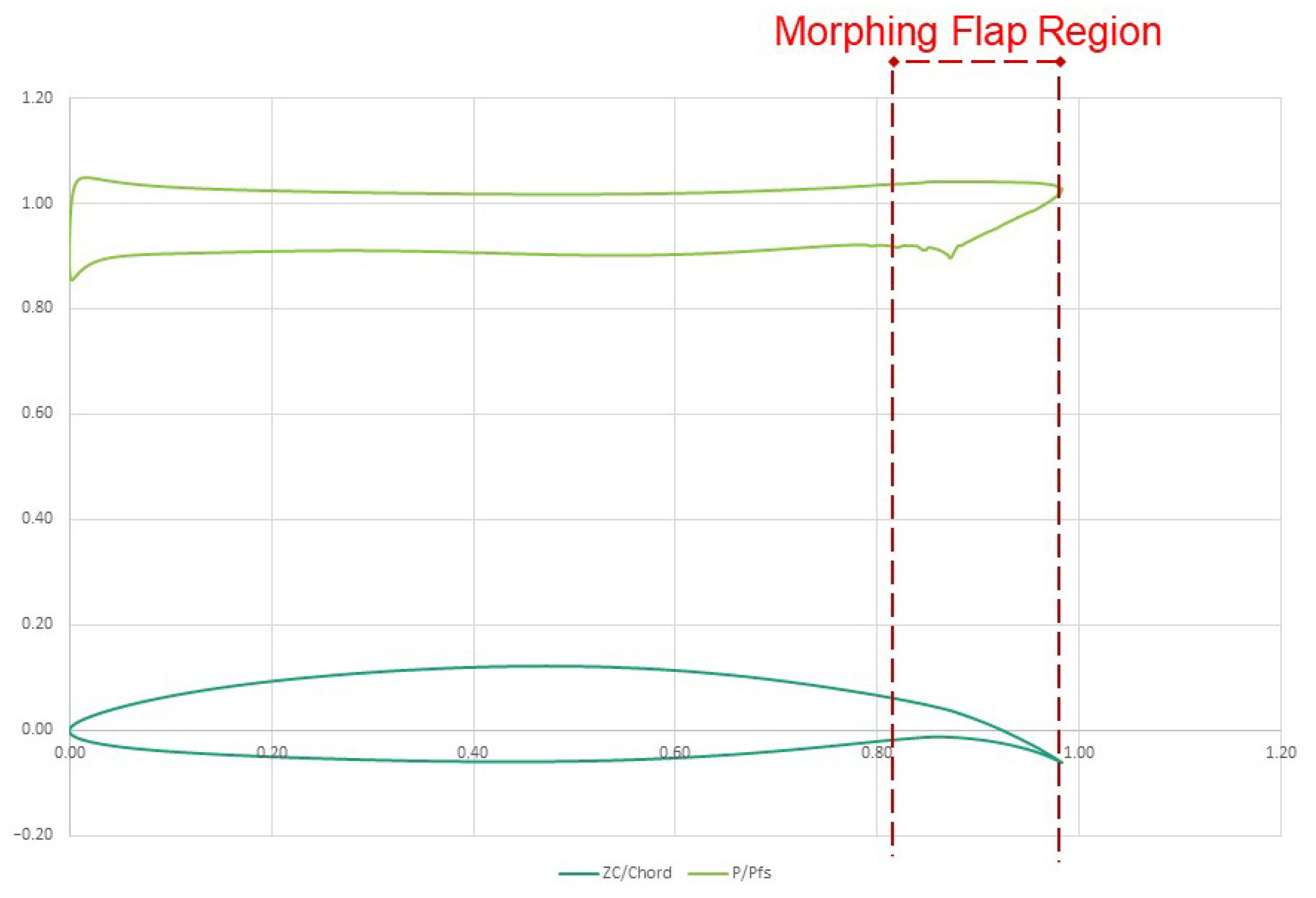
- A flapped (high-lift) condition corresponds to the maximum extended speed for the flap (VF) of 90 m/s and a load factor equal to 2.
- A clean (high-speed) condition related to the dive speed (VD) and load factor equal to 2.5.
3.2. Project Requirements and System Layouts
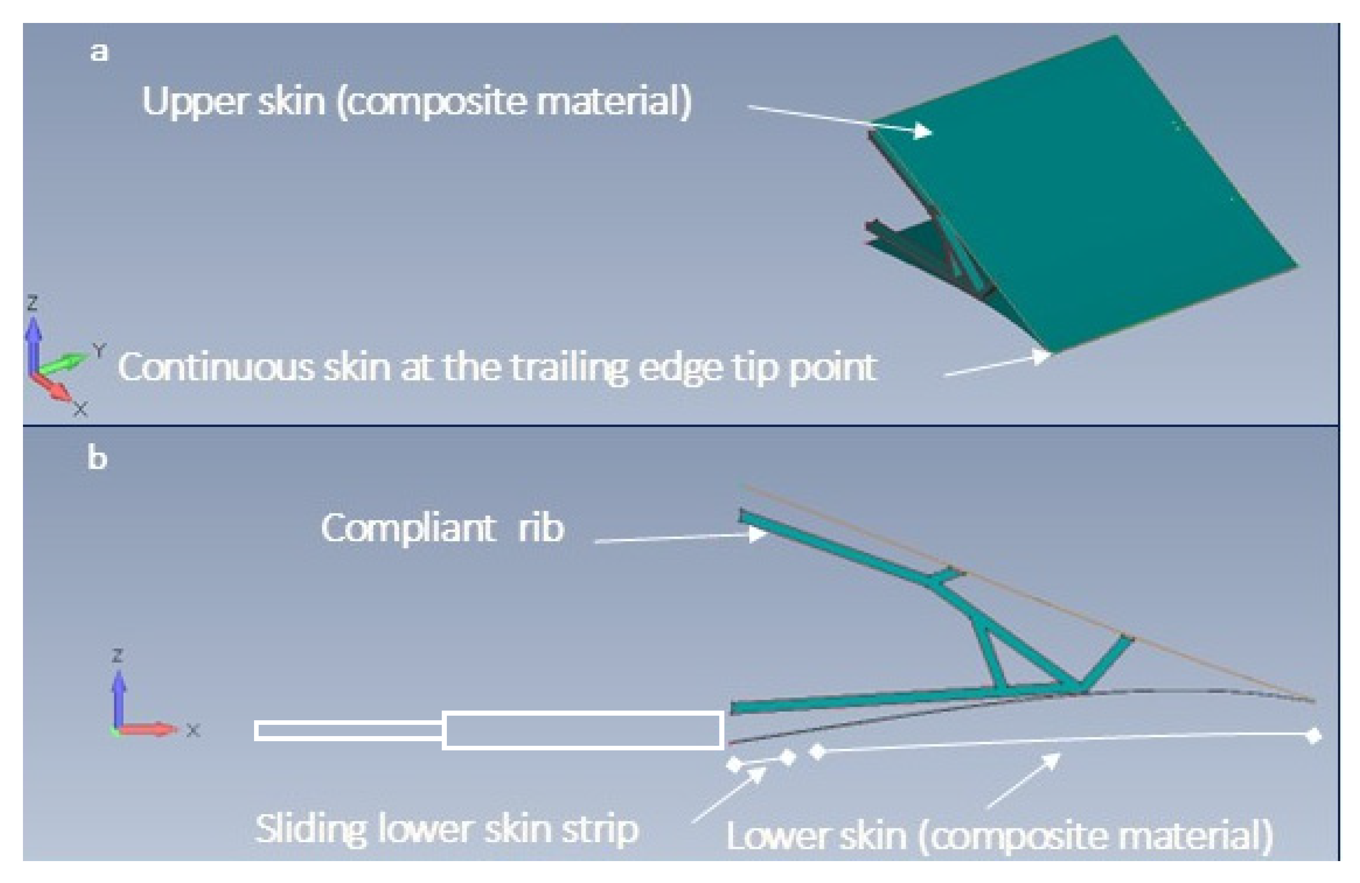
3.2.1. C1, Truss-Rib Configuration
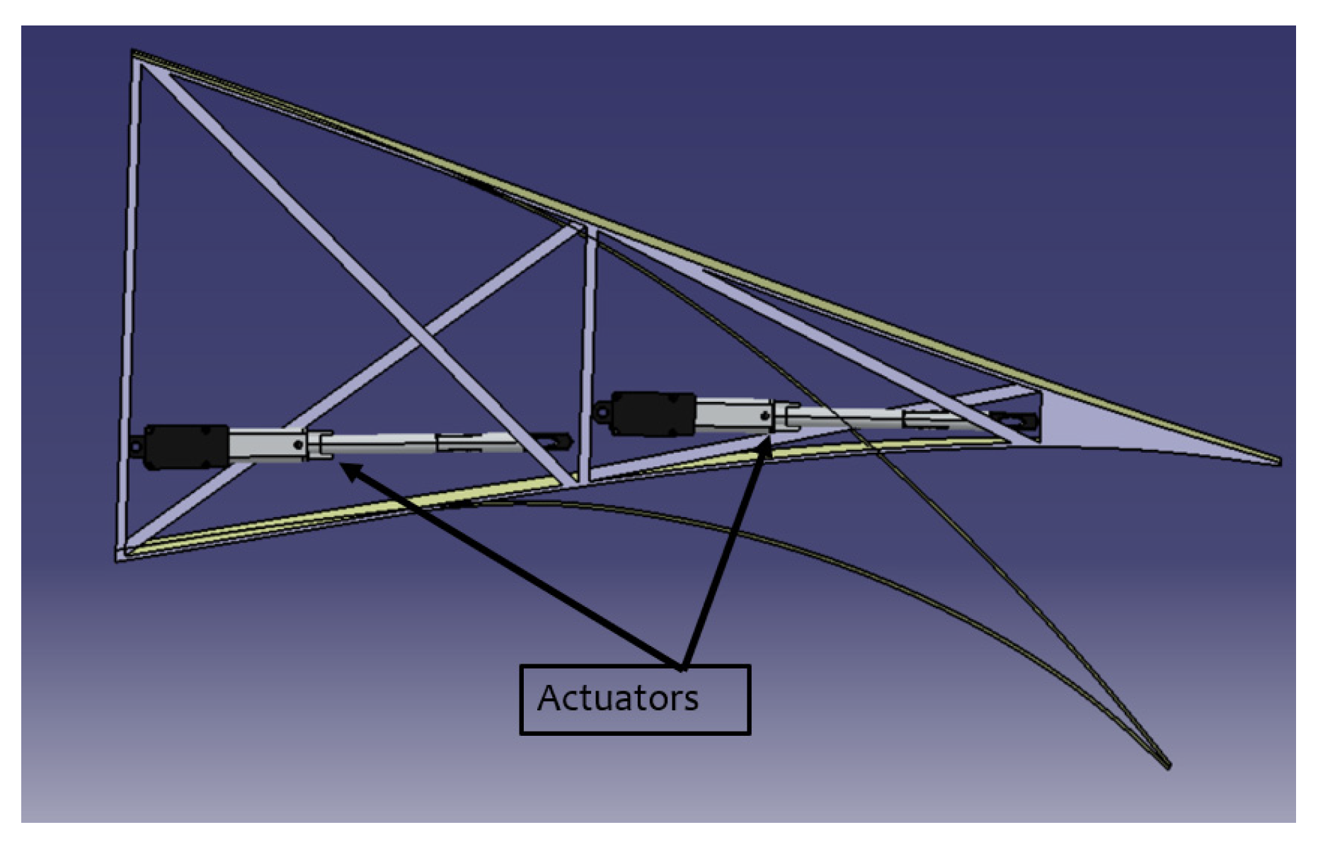
3.2.2. C2, X-Rib Configuration
3.3. Finite Element Models
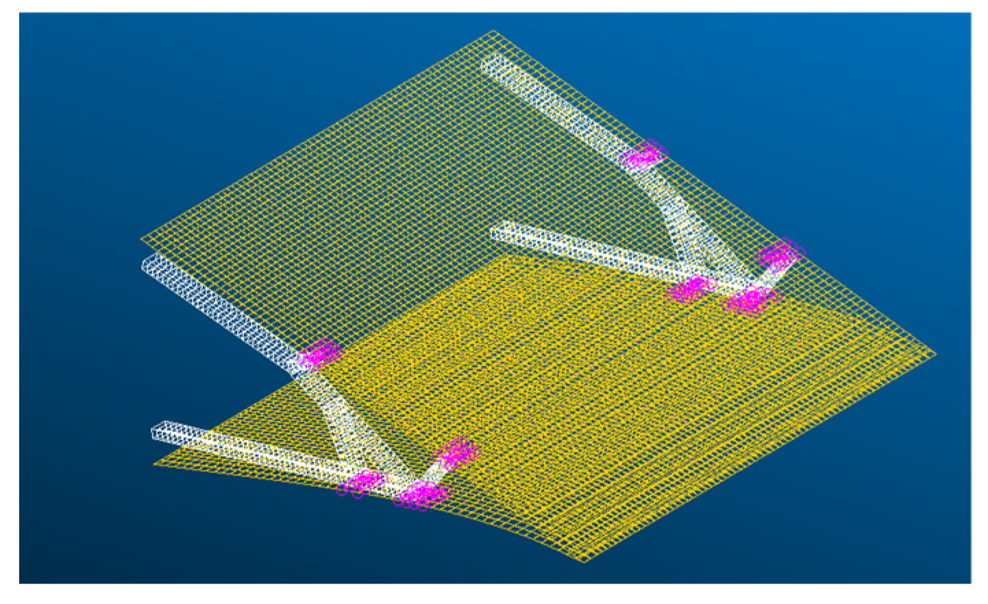
3.3.1. C1 FEM Description
- ▪
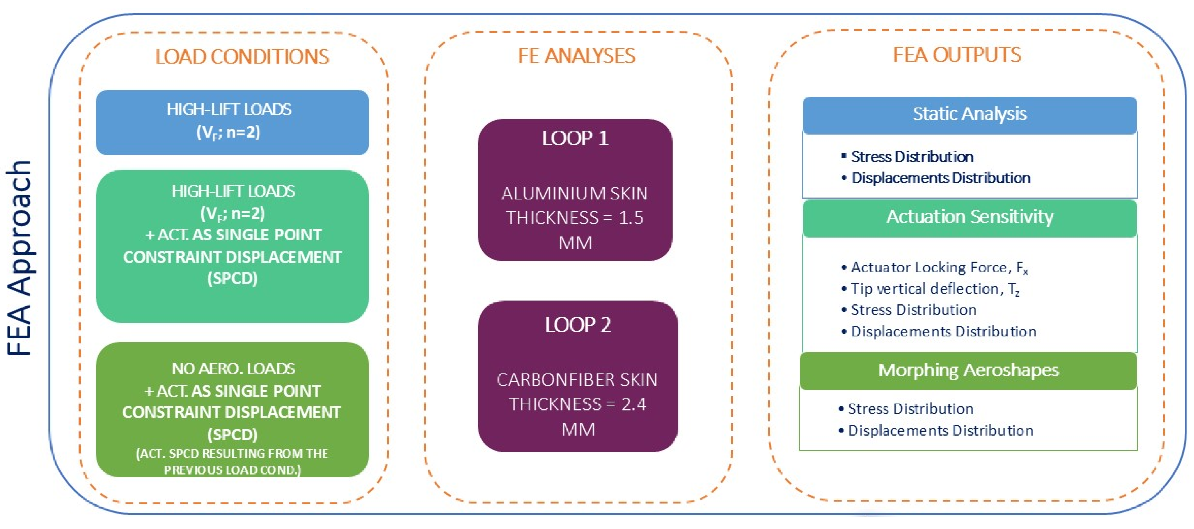
- Loop 1: Utilized aluminum as the material, with a uniform skin thickness of 1.5 mm.
- ▪
- Loop 2: Employed a carbon fiber laminate with a uniform skin thickness of 2.4 mm.
3.3.2. C2 FEM Description
- E = 7.00 × 10¹⁰ N/m2
- Poisson Ratio = 0.320
- G = 2.65 × 10¹⁰ N/m2
- ρ = 2780 kg/m3
3.4. Aero-Structural Mesh Matching
3.5. Finite Element Analyses and Optimization Results
3.5.1. C1 FEA and Results
- ▪
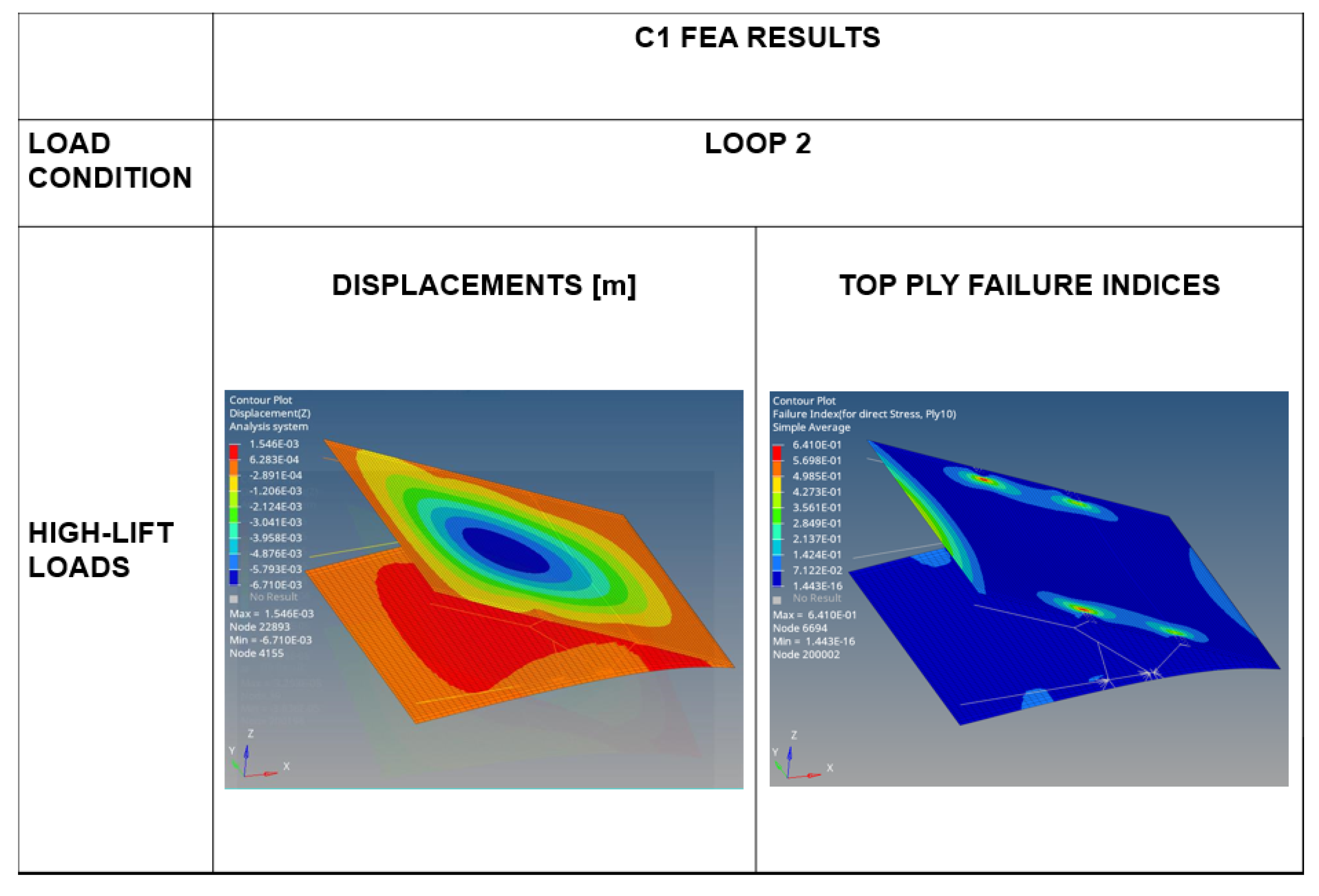
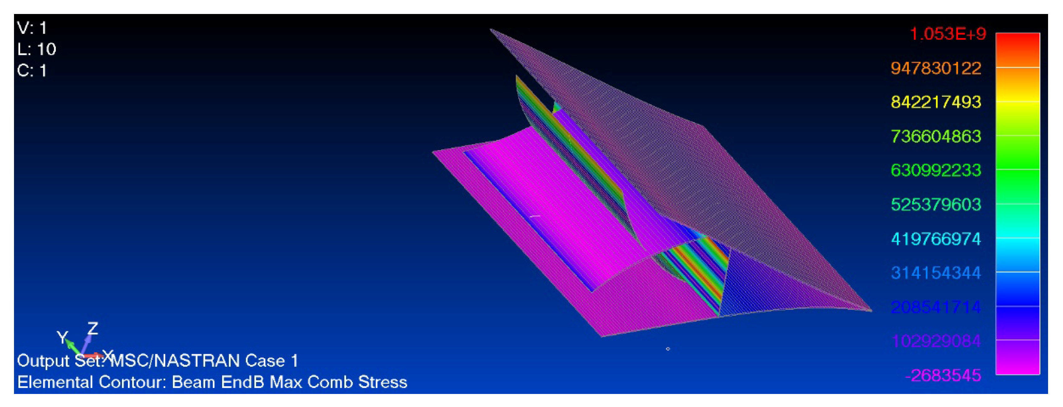
- High-lift flapped condition is used to perform static analyses in order to obtain stress/strain and displacement distribution along the MF.
- ▪
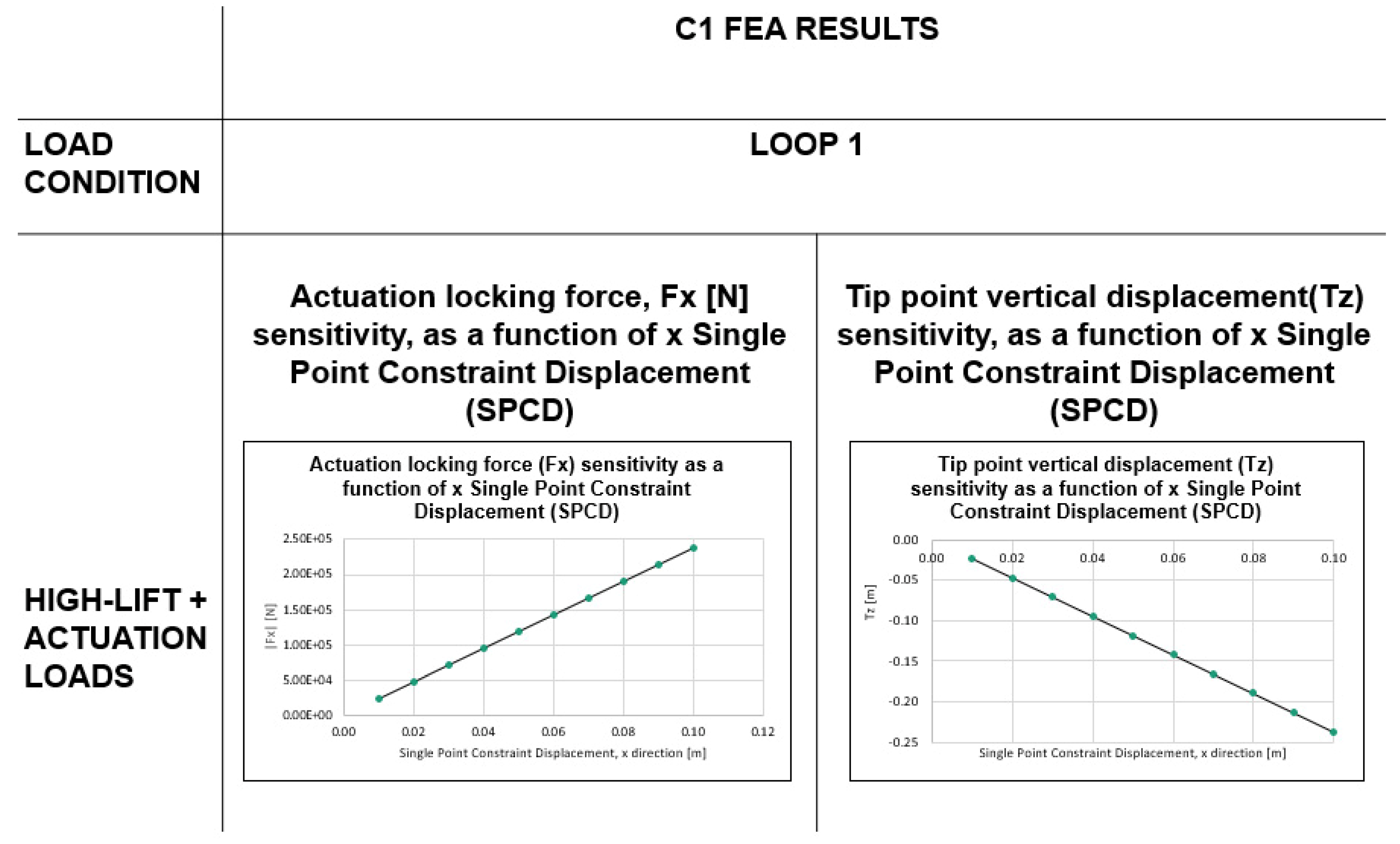
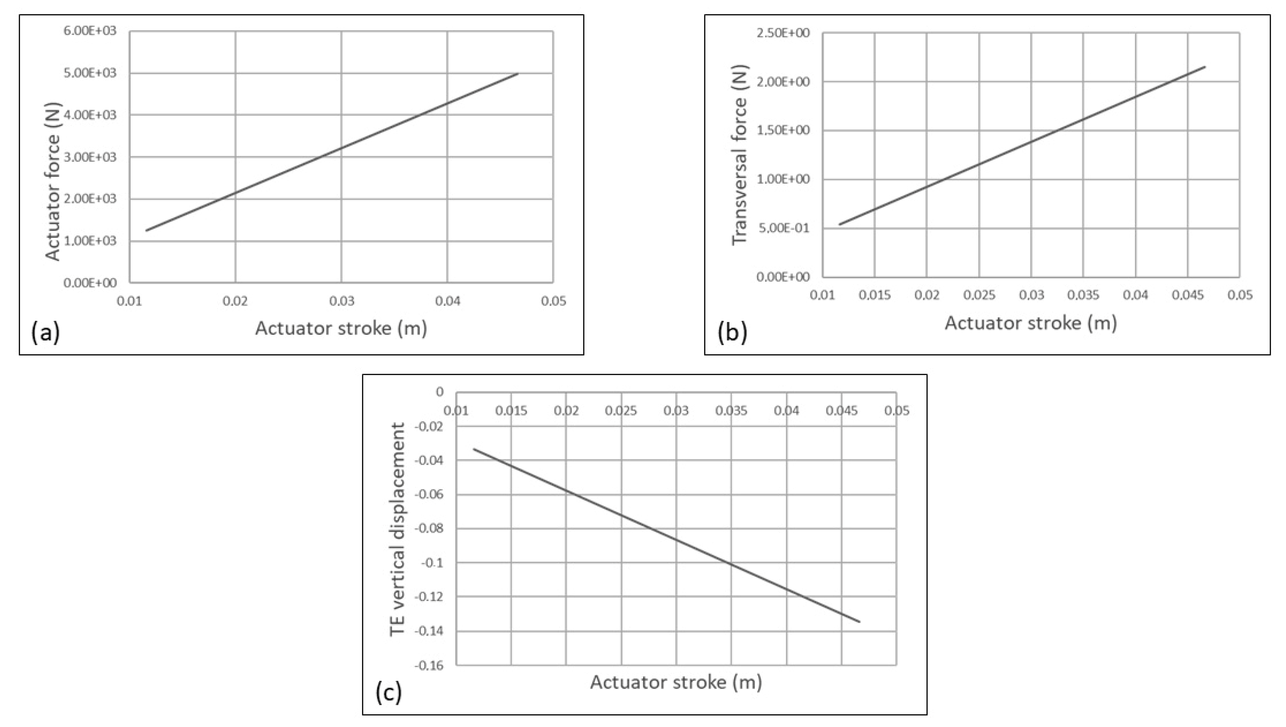
- High-lift flapped conditions combined with actuation loads are used to perform an actuation sensitivity analysis.
- ▪
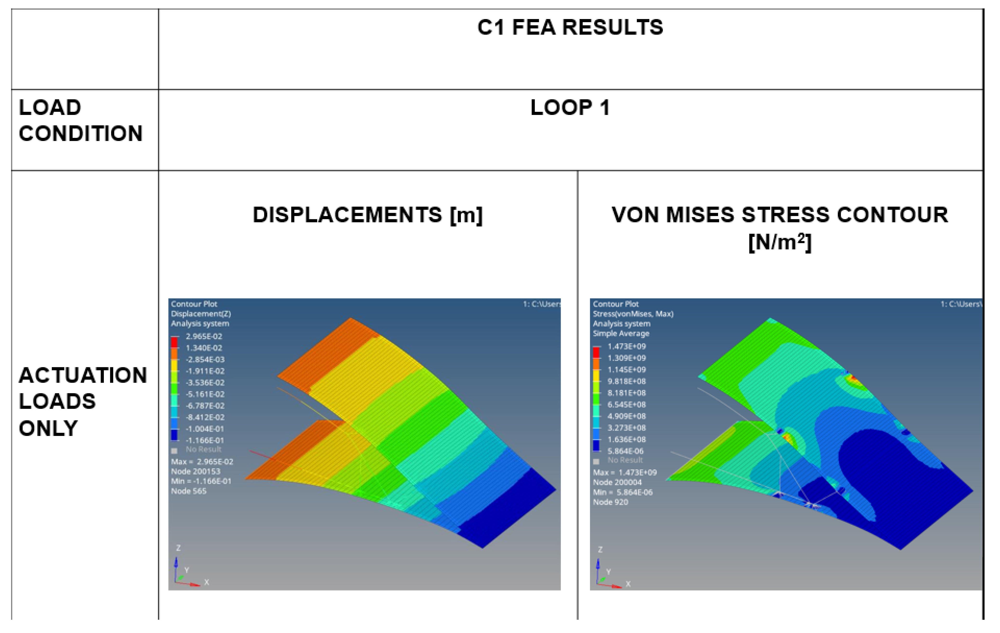
- Actuation loads in the absence of aerodynamic loads are used to obtain the morphing aeroshape of the MF.
- ▪
- The middle node of the lower skin.
- ▪
- Both lower rib attachment points.
- ▪
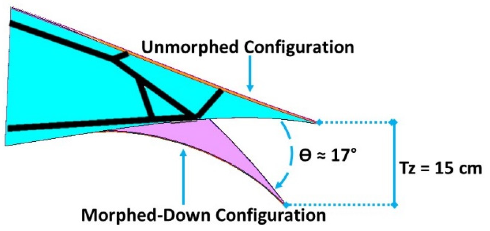
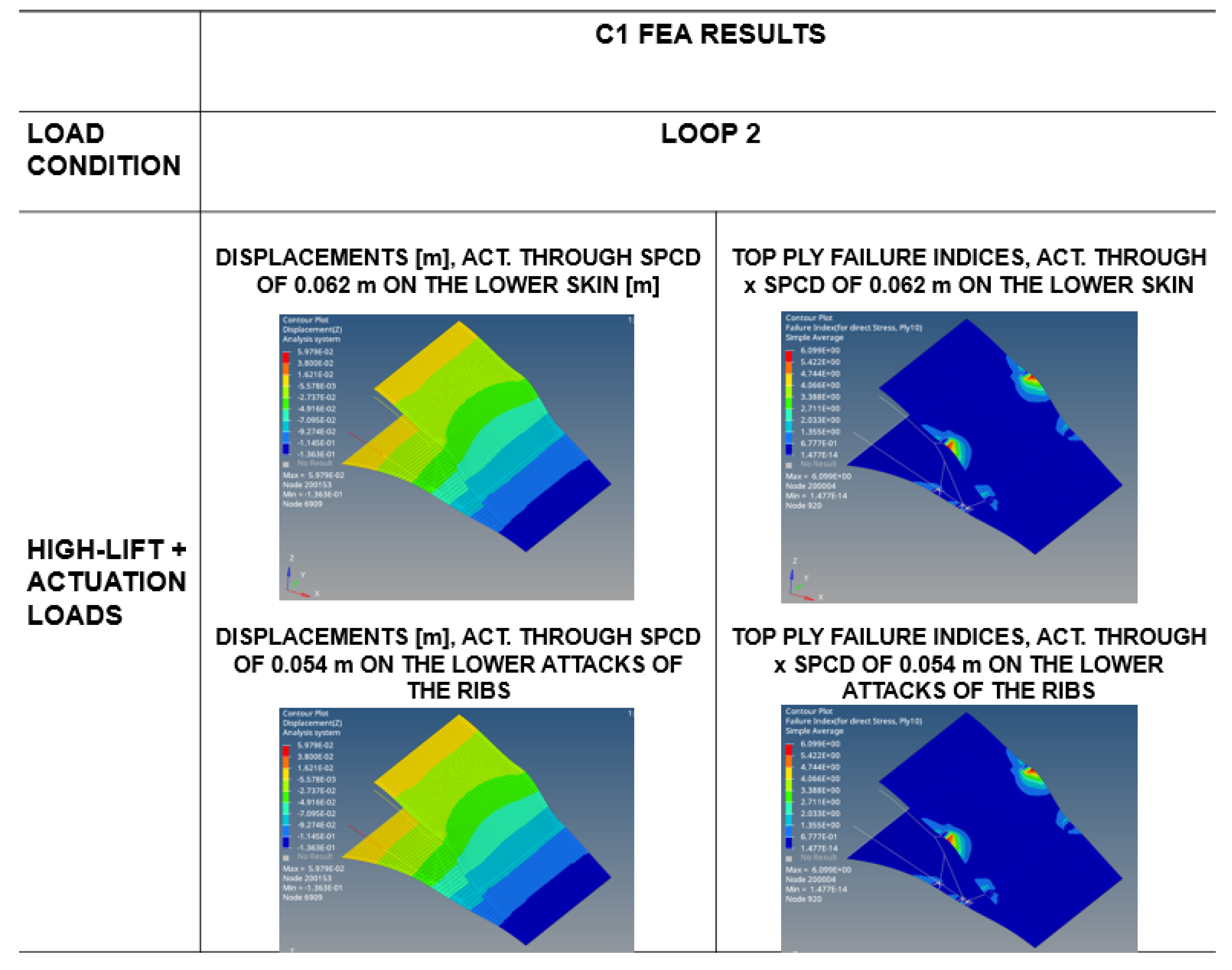
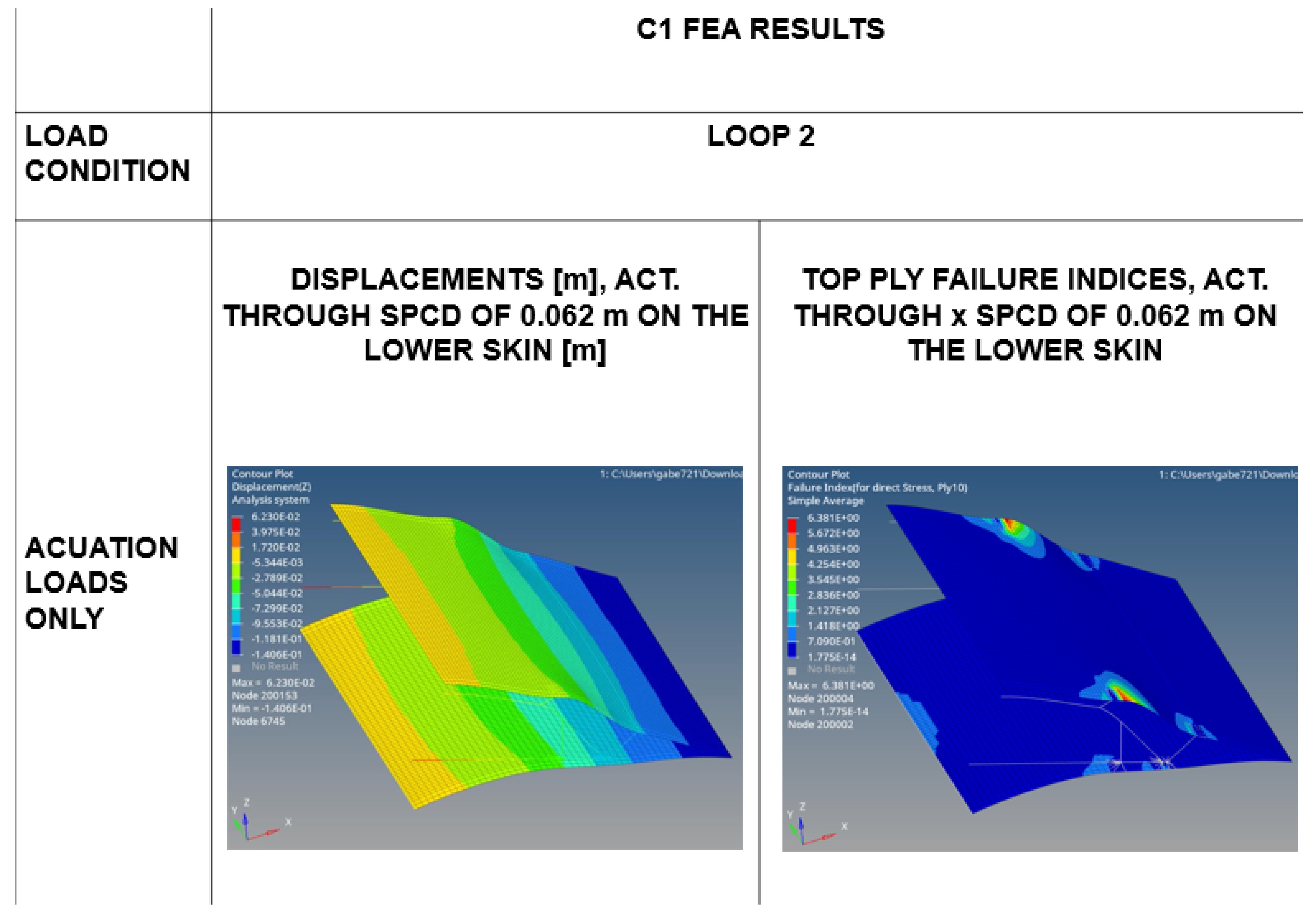
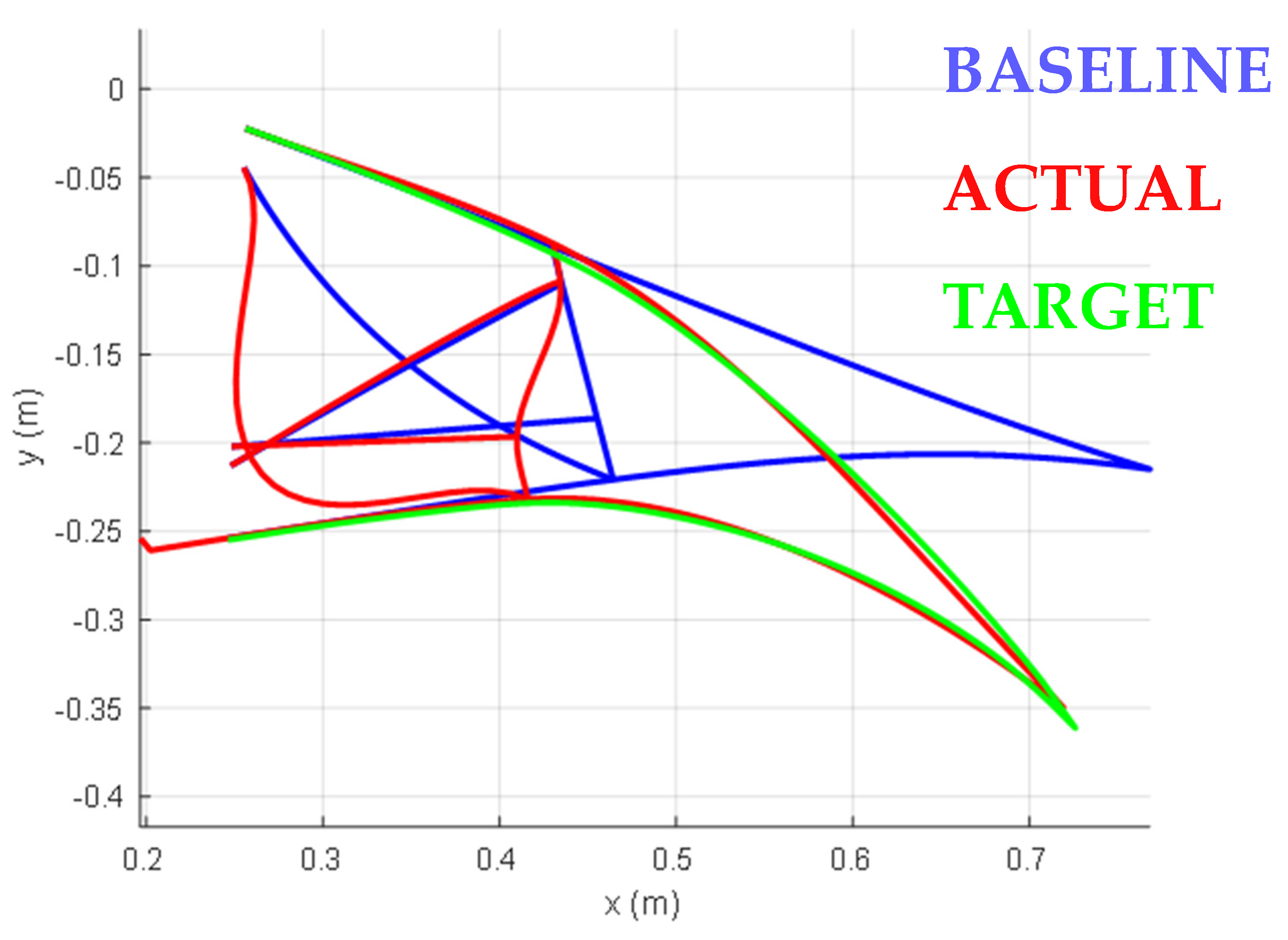
- When the lower skin is displaced by 0.062 m, the vertical deflection at the downward tip is approximately 1.4 × 10⁻¹ m, which is very close to the target Tz value. The failure indices for the top ply again reveal peaks at the junctions between the skin and the ribs.
- ▪
- Actuating the lower edges of the ribs by 0.054 m yields Tz results of around 1.5 × 10⁻¹ m, with a similar distribution of top ply failure indices as observed in the previous scenario.
- ▪
- In both cases analyzed, the ribs emerge as the most stressed structural components, highlighting the necessity for optimization in their design.
3.5.2. C2 FEA and Results
4. Conclusions
Author Contributions
Funding
Institutional Review Board Statement
Informed Consent Statement
Data Availability Statement
Acknowledgments
Conflicts of Interest
References
- Rea, F.; Amoroso, F.; Pecora, R.; Noviello, M.C.; Arena, M. Structural Design of a Multifunctional Morphing Fowler Flap for a Twin-Prop Regional Aircraft. In Proceedings of the Intervento Presentato al Convegno SMASIS 2018—Smart Materials, Adaptive Structures and Intelligent Systems Conference, San Antonio, TX, USA, 110–12 September 2018. Available online: https://hdl.handle.net/11588/724489 (accessed on 13 March 2025).
- Li, D.; Zhao, S.; Da Ronch, A.; Xiang, J.; Drofelnik, J.; Li, Y.; Zhang, L.; Wu, Y.; Kintscher, M.; Monner, H.P.; et al. A review of modelling and analysis of morphing wings. Prog. Aerosp. Sci. 2018, 100, 46–62. [Google Scholar]
- Smith, J.; Johnson, K. Aerodynamic Performance of Morphing Wings. Appl. Sci. 2022, 12, 1234–1245. [Google Scholar]
- Doe, J. Morphing Wing Technologies; Springer: Berlin, Germany, 2020; pp. 10–20. [Google Scholar]
- Lin, T.; Pecora, R.; Ciliberti, D.; Xia, W.; Hu, S. Aerodynamic optimization of an adaptive flap for next-generation green aircraft. Chin. J. Aeronaut. 2024, 37, 100–122. [Google Scholar] [CrossRef]
- Ameduri, S.; Concilio, A. Morphing in Aerospace: Aims, Challenges and Current Showstoppers; Italian Aerospace Research Centre: Capua, Italy, 2020; Available online: https://www.cira.it/it/Pubblicazioni/Lecture%20on%20adaptive%20structures%20v5.pdf (accessed on 6 January 2020).
- Kabganian, M.; Hashemi, S.M. Towards Design Optimization of Compliant Mechanisms: A Hybrid Pseudo-Rigid-Body Model–Finite Element Method Approach and an Accurate Empirical Compliance Equation for Circular Flexure Hinges. Biomimetics 2024, 9, 471. [Google Scholar] [CrossRef] [PubMed]
- Pecora, R.; Amoroso, F.; Arena, M.; Noviello, M.C.; Rea, F. Experimental validation of a true-scale morphing flap for large civil aircraft applications. In Proceedings of the SPIE; SPIE: Bellingham, WA, USA, 2017; p. 101660L. [Google Scholar] [CrossRef]
- Esposito, M.; Roy, R.; Surace, C.; Gherlone, M. Hybrid Shell-Beam Inverse Finite Element Method for the Shape Sensing of Stiffened Thin-Walled Structures: Formulation and Experimental Validation on a Composite Wing-Shaped Panel. Sensors 2023, 23, 5962. [Google Scholar] [CrossRef] [PubMed]
- Smith, A.M.O. High-lift aerodynamics. J. Aircr. 1975, 12, 501–530. [Google Scholar] [CrossRef]
- Strüber, H. The aerodynamic design of the A350 XWB-900 high lift system. In Proceedings of the 29th International Congress of the Aeronautical Sciences, St. Petersburg, Russia, 7–12 September 2014. [Google Scholar]
- Cavalieri, V.; De Gaspari, A.; Ricci, S. Optimization of compliant adaptive structures in the design of a morphing droop nose. Smart Mater. Struct. 2020, 29, 075020. [Google Scholar] [CrossRef]
- Monner, H.P.; Breitbach, E.; Bein, T.; Hanselka, H. Design aspects of the adaptive wing–the elastic trailing edge and the local spoiler bump. Aeronaut. J. 2000, 104, 89–95. [Google Scholar] [CrossRef]
- Kintscher, M.; Monner, H.P.; Heintze, O. Experimental testing of a smart leading edge high lift device for commercial transportation aircrafts. In Proceedings of the 27th International Congress of the Aeronautical Sciences (ICAS), Nice, France, 19–24 September 2010. [Google Scholar]
- Woelcken, P.C.; Papadopoulos, M. (Eds.) Smart Intelligent Aircraft Structures (SARISTU)—Proceedings of the Final Project Conference; Springer International Publishing: Cham, Switzerland, 2016; ISBN 978-3-319-22413-8. [Google Scholar]
- Concilio, A.; Dimino, I.; Pecora, R. SARISTU: Adaptive Trailing Edge Device (ATED) design process review. Chin. J. Aeronaut. 2020, 34, 187–210. [Google Scholar]
- Concilio, A.; Dimino, I.; Lecce, L. (Eds.) Morphing Wing Technologies for Large Commercial Aircraft and Helicopter Scenario; Butterworth-Heinemann: Kidlington, UK, 2018; ISBN 978-0-08-100964-2. [Google Scholar]
- Kota, S.; Osborn, R.; Ervin, G.; Maric, D.; Flick, P.; Paul, D. Mission Adaptive Compliant Wing–Design, Fabrication and Flight Test; RTO Applied Vehicle Technology Panel (AVT) Symposium; NATO Science and Technology Organization: Paris, France, 2009. [Google Scholar]
- Hetrick, J.A.; Kota, S. An energy formulation for parametric size and shape optimization of compliant mechanisms. J. Mech. Des. 1999, 121, 229–234. [Google Scholar] [CrossRef]
- Kerr-Jia, L.; Kota, S. Topology and dimensional synthesis of compliant mechanisms using discrete optimization. J. Mech. Des. 2006, 128, 1080–1091. [Google Scholar]
- Ameduri, S.; Galasso, B.; Noviello, M.C.; Dimino, I.; Concilio, A.; Catalano, P.; D’Aniello, F.A.; Carossa, G.M.; Pinazo, L.; Derry, J.; et al. Design and optimization of a compliant morphing trailing edge for high-lift generation. Appl. Sci. 2025, 15, 2529. [Google Scholar] [CrossRef]
- Catalano, P.; Diodati, G.; Lucariello, D.; Vitagliano, P. Aero-structural design of a high-aspect ratio wing. In Proceedings of the AIAA SciTech Forum, Orlando, FL, USA, 8–12 January 2024. [Google Scholar]
- Noviello, M.C.; Dimino, I.; Ameduri, S.; Concilio, A. Conceptual Design and Topology Optimization of a Compliant Morphing Flap for the Next Generation Hybrid-Electric Regional Aircraft. In Proceedings of the 34th ICAS Conference, Florence, Italy, 9–13 September 2024. [Google Scholar]
- De Gaspari, A.; Cavalieri, V.; Ricci, S. Experimental and Performance Validation of a Full-Scale Morphing Droop Nose Design Based on Composite Compliant Structures. Compos. Struct. 2024, 348, 118502. [Google Scholar] [CrossRef]
- Cavalieri, V.; De Gaspari, A.; Ricci, S. Aero-Structural Design Optimization of a Morphing Aileron Considering Actuation Aspects. In Proceedings of the AIAA SCITECH 2024 Forum, Clean Aviation Special Session: Innovative Aircraft Concepts and Novel Configurations, Orlando, FL, USA, 8–12 January 2024. [Google Scholar] [CrossRef]
- De Gaspari, A.; Cavalieri, V.; Corti, M.; Ricci, S. Multi-Objective Design Optimization of a Morphing Aileron for a Hybrid Electric Regional Aircraft. In Proceedings of the 34th ICAS Conference, Florence, Italy, 9–13 September 2024. [Google Scholar]



| Parameter | Description | Range |
|---|---|---|
| p1 | Fore X-spar connection node (point A) | 1–87 (top skin nodes between 1 and 100) |
| p2 | Fore X-spar connection node (point B) | 102–188 (top skin nodes between 101 and 200) |
| p3 | Location of edge C of the fore X spring | Parametric on dashed segment |
| p4 | Location of edge D of the fore X spring | |
| p5 | Spar thickness | 1–3 mm |
| p6 | Location of edge E of the fore X spring | Parametric on the upper half zone of the web vertical edge |
| p7 | Location of edge F of the fore X spring | Parametric on the lower half zone of the web vertical edge |
| p8 | The curvature of the BC plate of the X | −25–+25 mm |
| p9 | Thickness on the middle of the DE plate of the X | 1–3 mm |
| p10 | Thickness on the edges of the DE plate of the X | |
| p11 | Depth of the edges of the DE plate of the X | 10–400 mm |
| p12 | Depth of the middle of the DE plate of the X | |
| p13 | The curvature of the DE plate of the X | −25–+25 mm |
| p14 | Thickness on the middle of the BC plate of the X | 1–3 mm |
| p15 | Thickness on the edges of the BC plate of the X | |
| p16 | Depth of the edges of the BC plate of the X | 10–400 mm |
| p17 | Depth of the middle of the BC plate of the X | |
| p18 | Location of hinge G of the actuator | Parametric on dashed segment |
| p19 | Location of hinge H of the actuator | Parametric on the web vertical edge |
Disclaimer/Publisher’s Note: The statements, opinions and data contained in all publications are solely those of the individual author(s) and contributor(s) and not of MDPI and/or the editor(s). MDPI and/or the editor(s) disclaim responsibility for any injury to people or property resulting from any ideas, methods, instructions or products referred to in the content. |
© 2025 by the authors. Licensee MDPI, Basel, Switzerland. This article is an open access article distributed under the terms and conditions of the Creative Commons Attribution (CC BY) license (https://creativecommons.org/licenses/by/4.0/).
Share and Cite
Noviello, M.C.; Galasso, B.; Dimino, I.; Ameduri, S.; Concilio, A. Trade-Off Conceptual Design of a Camber Morphing Flap for the Next Generation Hybrid Electrical Aircraft Across the HERWINGT Project. Appl. Sci. 2025, 15, 3660. https://doi.org/10.3390/app15073660
Noviello MC, Galasso B, Dimino I, Ameduri S, Concilio A. Trade-Off Conceptual Design of a Camber Morphing Flap for the Next Generation Hybrid Electrical Aircraft Across the HERWINGT Project. Applied Sciences. 2025; 15(7):3660. https://doi.org/10.3390/app15073660
Chicago/Turabian StyleNoviello, Maria Chiara, Bernardino Galasso, Ignazio Dimino, Salvatore Ameduri, and Antonio Concilio. 2025. "Trade-Off Conceptual Design of a Camber Morphing Flap for the Next Generation Hybrid Electrical Aircraft Across the HERWINGT Project" Applied Sciences 15, no. 7: 3660. https://doi.org/10.3390/app15073660
APA StyleNoviello, M. C., Galasso, B., Dimino, I., Ameduri, S., & Concilio, A. (2025). Trade-Off Conceptual Design of a Camber Morphing Flap for the Next Generation Hybrid Electrical Aircraft Across the HERWINGT Project. Applied Sciences, 15(7), 3660. https://doi.org/10.3390/app15073660


