Article

Trade-Off Conceptual Design of a Camber Morphing Flap for the Next Generation Hybrid Electrical Aircraft Across the HERWINGT Project

by
Maria Chiara Noviello
1,*,
Bernardino Galasso
1,
Ignazio Dimino
2,
Salvatore Ameduri
1 and
Antonio Concilio
3
1
Adaptive Structures Division, The Italian Aerospace Research Centre (CIRA), 81043 Capua, Italy
2
Strategic Planning and Institutional Relations, The Italian Aerospace Research Centre (CIRA), 81043 Capua, Italy
3
Technical and Program Coordination, The Italian Aerospace Research Centre (CIRA), 81043 Capua, Italy
*
Author to whom correspondence should be addressed.
Appl. Sci. 2025, 15(7), 3660; https://doi.org/10.3390/app15073660
Submission received: 10 February 2025 / Revised: 14 March 2025 / Accepted: 14 March 2025 / Published: 26 March 2025
(This article belongs to the Section Aerospace Science and Engineering)

Abstract

:
Compliant wing morphing devices deal with controlled and smooth adaptation of the subcomponents’ shape to external conditions. Their structural stiffness distribution, typically resulting from an optimization design process, is tailored to ensure large deformations and sufficient robustness while preserving a given form under the action of the aerodynamic loads and the internal force system. Within the European project HERWINGT (Hybrid Electric Regional Wing Integration Novel Green Technologies), supported by the Clean Aviation Joint Undertaking (CAJU), a compliant morphing flap (MF) concept has been developed by CIRA to implement adaptive capability for a strut-braced wing of the next generation Hybrid Electric Regional Aircraft. Its aim is to achieve remarkable high-lift performance improvement and related reduction of fuel consumption per flight. Specifically, the work focuses on the evolution of the conceptual architecture of the MF developed across the HERWINGT project, which was investigated in terms of preliminary design and has always accounted for actuation system integration aspects. A step-by-step design approach involving sensitivity finite elements analyses has been then carried out on two MF configurations; the technical outcomes resulting from the development of each of them have been critically analyzed and herein reported. Finally, justifications are provided for all the future adoptable engineering solutions.

1. Introduction

In civil aviation, morphing flaps are garnering increased attention from the technological and scientific communities. This interest is driven by the potential advantages offered at the aircraft level, particularly in enhancing high-lift performance and reducing fuel consumption. By exploiting morphing capabilities, it becomes feasible to adopt a single-flap configuration and adjust its shape to meet the aerodynamic take-off and landing requirements. By avoiding multiple-part high-lift architectures, the design is largely simplified.
Those systems (such as Fowler/Kruger flaps, slats, droops, etc.) play a crucial role at low-velocity regimes; in that case, the wing’s performance requirements are pursued by increasing max lift coefficient (CL,max) and stall angle, resulting in increased carried-load capacity. Their deployment requires an intricate design of the mechanism system that is in line with the flight parameters, also accounting for mobility constraints due to possible limited range of motion. For instance, in the case of the common triple-slotted fowler flap [1], only three rotations shape the camber variations. Furthermore, negative rotation (upper-wise) is usually not permitted.
Recently, there has been significant interest in morphing structures to better adapt to different flight conditions [2,3,4,5,6,7,8,9]. In reference [5], the study therein reported comparing different morphing flap (MF, in what follows) architectures through 2D and 3D simulations to define an optimal configuration. Predictions indicated that lift and efficiency could increase by several percentage points, with notable differences observed between take-off and landing, as expected. The selected morphing trailing edge could modify its shape in several ways, adding degrees of freedom, if compared to a conventional one, to face different environments. Combined with adaptive control technologies, these morphing structures offer unprecedented potentialities for next-generation aircraft, enabling rapid responses to operational changes, safer take-offs and landings, and improved fuel efficiency.
Research by Smith et al. [10] showed that high-lift devices equipped with multiple elements and slits can significantly enhance lift for wings. This is why double- and triple-slotted flaps were initially implemented in large commercial aircraft, such as B707, B737, and A300. The complexity of multi-element high-lift systems is, however, strictly related to maintenance and repair costs. To simplify deployment mechanisms, with the aim of facilitating the production and operation aspects, single-slotted flap configurations have recently gained popularity in commercial aviation. For example, the Adaptive Dropped Hinge Flap (ADHF) [11] was introduced on the A350 XWB-900 to decrease the weight and complexity of the devices while using a slotted camber tab configuration.
Adaptive camber is among the most promising concepts of morphing technologies, particularly suitable for adjusting the airfoil curvature to foster high-lift aerodynamic performances. Over the years, various experimental approaches have been proposed and tested to achieve that goal by using flexible skins connected to rigid mechanisms, including rigid levers and kinematic joints, with initial developments originating from Boeing and NASA (National Aeronautics and Space Administration) [12].
In relation to the trailing edge, Monner (1995) [13] proposed a finger-like concept as part of the ADIF project, which utilized ribs made of multiple plates connected by revolute joints and attached to the skin via sliding joints. Years later, Monner also explored a morphing solution to replace the conventional droop nose device on typical Airbus aircraft (2010) [14], designed by employing optimization techniques. The design of this high-lift device is aimed at realizing a seamless and gapless wing structure to minimize acoustic emissions and drag while ensuring laminarity.
Several other EU projects, including SADE [15] and SARISTU [16], targeted similar goals, focusing on the incorporation of morphing with standard features such as de-icing, erosion and bird-strike protection. Among the morphing demonstrators released in SARISTU by integrated European teams, a full-scale Adaptive Trailing Edge was set up, aimed at compensating the weight variation of the aircraft along the flight [17]. A wide and structured assessment of the technology in that time frame (2017) is reported in [17].
In general, solutions based on kinematic systems, made of namely rigid elements, face common challenges associated with mechanical components and exhibit the drawbacks of having multiple assembled parts. Alternatively, compliant morphing architectures convert actuation inputs into desired motions or shape changes by driving an elastic deformation throughout the structure. Unlike rigid mechanisms, these layouts are designed as single units without joints, resulting in greater fatigue liFEM and enhanced reliability. Additionally, these structures do not require specific assembly tools and are free from issues related to friction or backlash. Furthermore, they are generally easier to manufacture, leading to significant time and cost efficiencies. Finally, they can combine good kinematic and load–bearing properties.
Lack of hinges, whether flexible or rigid, reduces stress concentrations, ensuring gapless and smoothly deformable wing structures. Thus, compliant structures may substitute traditional high-lift systems and control surfaces, implementing morphing technology and simplifying current solutions based on kinematics. FlexSys Inc. carried out a relevant in-flight demonstration of this principle in partnership with the AFRL (US Air Force Research Laboratory) and NASA on a Gulfstream III equipped with the FlexFoil™ Adaptive Compliant Trailing Edge (ACTE) [18]. Such work was possible through the development of proper synthesis procedures [19] and dedicated topology multi-phase optimization algorithms to design the compliant structure aimed at driving the solution to extreme accuracy and surface refinements [20].
Over the past decade, the Italian Aerospace Research Centre (CIRA), in what follows, has developed original optimization design procedures for compliant morphing structures [21]. Such methodologies are applied in the EU–funded Clean Aviation HERWINGT project, where some morphing technologies applications (specifically for a droop nose, flaps and ailerons) are being fostered for a strut-braced, high aspect-ratio wing, suitable for next-generation Hybrid-Electric Regional Aircraft [22].
In detail, the Adaptive Structures Unit of CIRA drives the realization of a wing-integrated compliant morphing flap, with a specific focus on the full-size structural design of the integrated camber morphing flap. The device will undergo static, dynamic, and fatigue tests, which refer to classical standard production parameters. The workflow is synthetically and graphically represented in Figure 1.
The paper is structured as follows: the approach for the design of the compliant adaptive component is introduced first, followed by the outcomes of the conceptual design in terms of system layout, actuation system, and finite element (FE) model description for two different configurations. Subsequently, the results obtained by applying the proprietary design procedure to the full-scale numerical models of the demonstrator (DEMO) are presented. Finally, the main conclusions and key lessons learned are discussed.

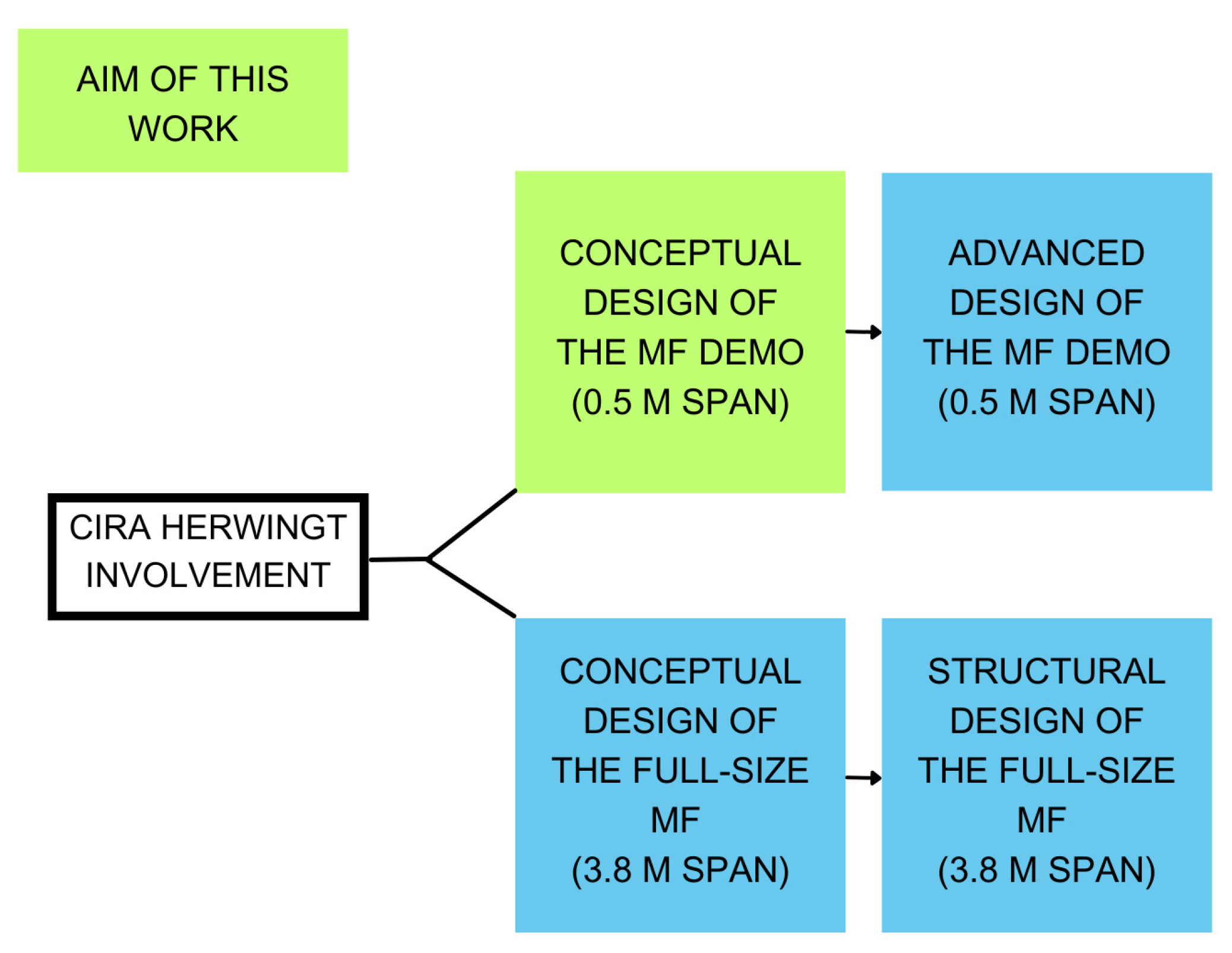
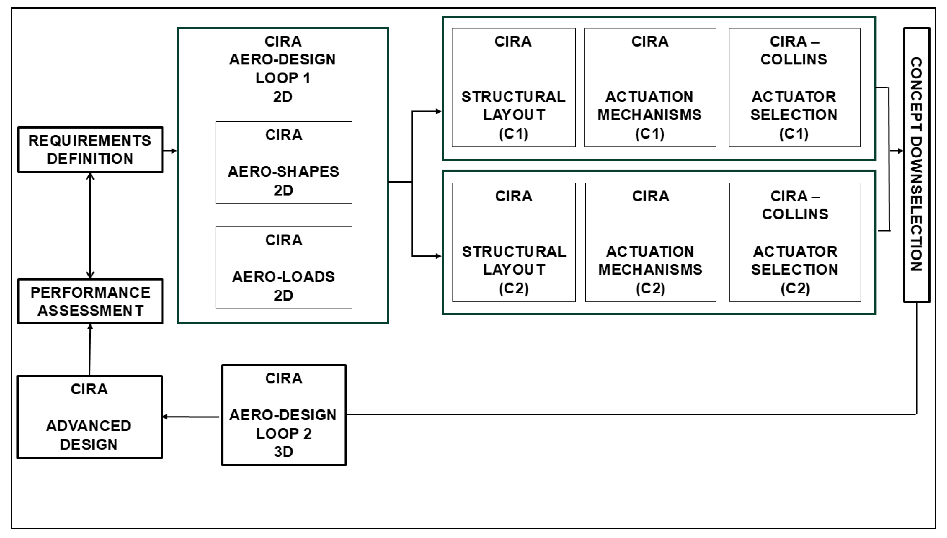
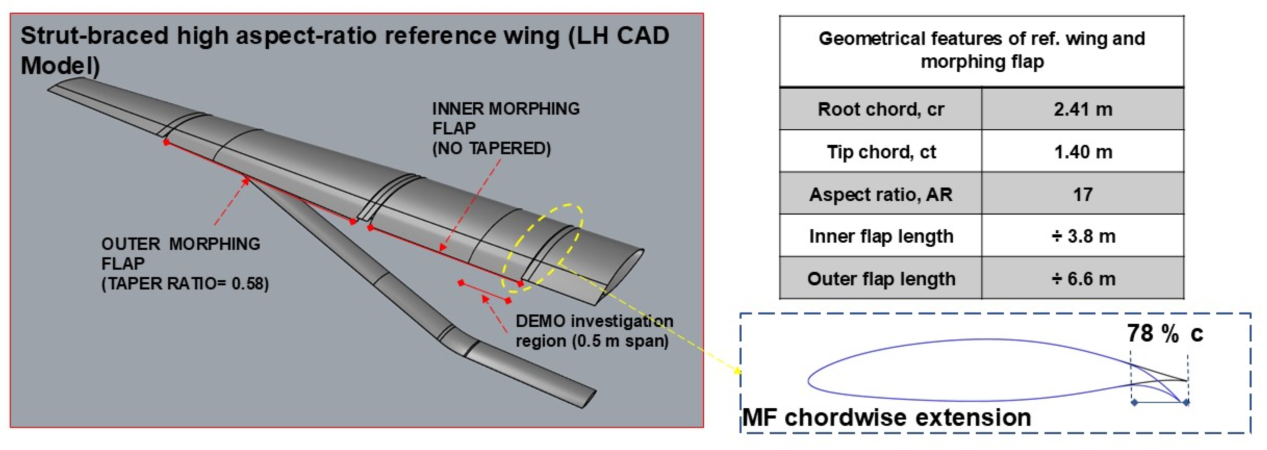
2. Design Approach and Reference Wing

A tailored multi-stage design approach was employed to develop a camber morphing flap for integration into a single bay 0.5 m wide demonstrator suitable for a high aspect ratio wing in next-generation hybrid electric aircraft. This approach is illustrated in Figure 2.
Starting from the requirement definition, a first preliminary 2D aerodynamic assessment was performed to obtain aero-shapes and loads [22]. These data were used in parallel as input for two different configurations, namely C1 and C2, developed and studied in terms of structural layout and actuation systems, also taking into account integration constraints for the actuation [23].
The concept down-selection led to a new third configuration, C3, implementing the best features resulting from C1 and C2. The description of the C3 configuration, which is then used for the 3D aerodynamic assessment and finally drives the advanced design of the MF DEMO, is out of the scope of this work.
For both C1 and C2 configurations, a compliant architecture was chosen to implement wing morphing capability. In general terms, compliant morphing devices enable the precise deformation of subcomponents to seamlessly alter the overall shape of the assembly. The structural stiffness is carefully optimized to provide sufficient compliance for accommodating significant deformations while also ensuring enough robustness to maintain a specific shape when subjected to external aerodynamic forces [7].
Figure 3 shows the reference wing, with a tabular detail on the geometrical features. The investigation region selected for the development of the MF DEMO design belongs to the untapered inner flap root section, with a rectangular shape and a span extension of 0.5 m.

3. Conceptual Design

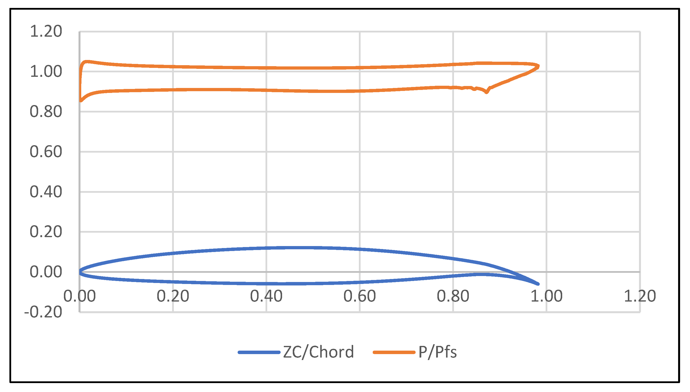
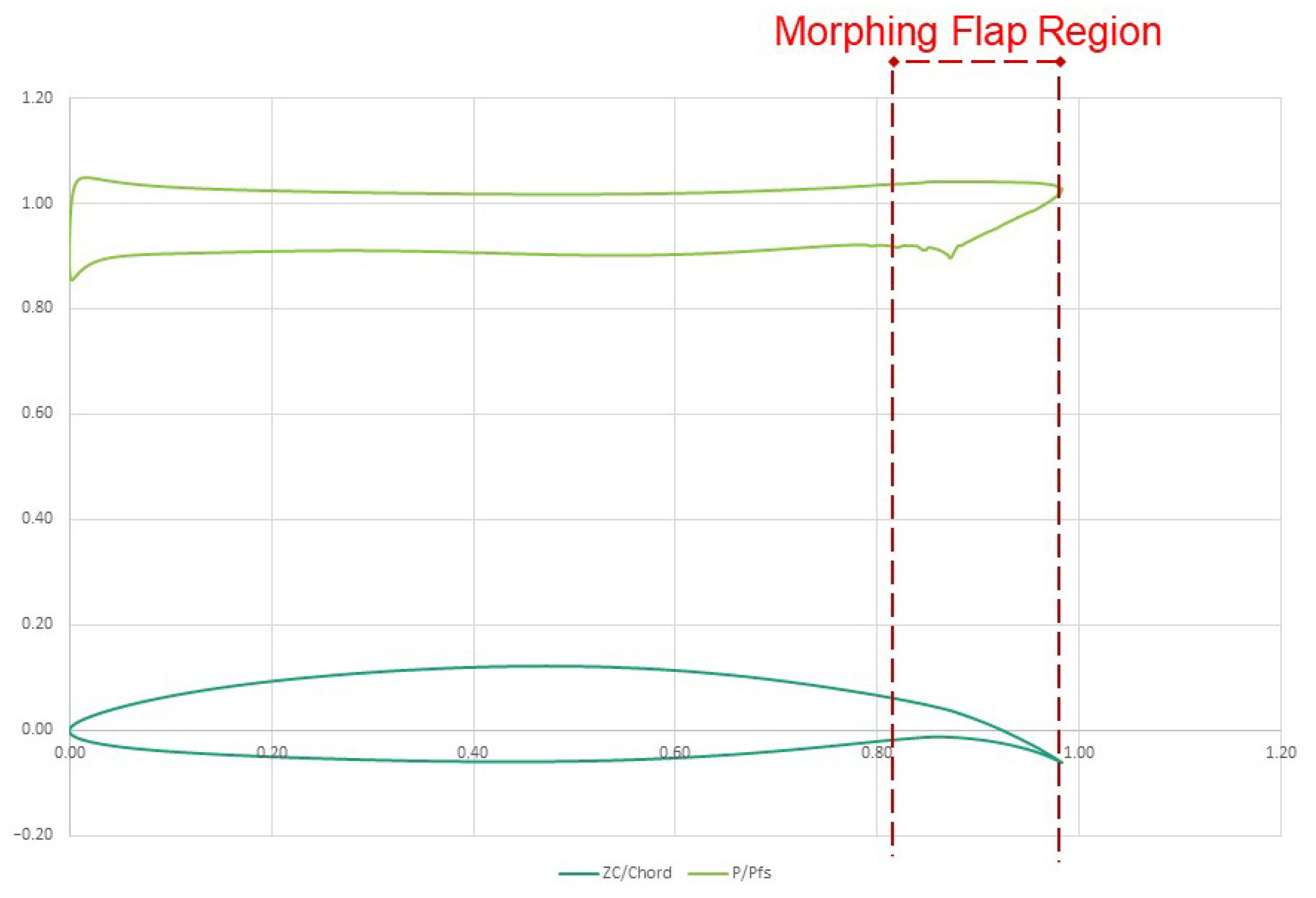
3.1. Aerodynamic Assessment

The wing load calculation was performed by the CIRA aerodynamic team by using the in-house (Unsteady Zonal Euler Navier Stokes) RANS (Reynolds-Averaged Navier Stokes) flow solver (compressible RANS equations on structured multi-block domains). As explained in [22,23], the aerodynamic assessment was obtained by considering as a preliminary assumption a constant load distribution along the span of the wing. The 2D profile for the calculation was selected as the one corresponding to the peak of the wing load. The aerodynamic loads evaluation was achieved under two conditions:
  • A flapped (high-lift) condition corresponds to the maximum extended speed for the flap (VF) of 90 m/s and a load factor equal to 2.
  • A clean (high-speed) condition related to the dive speed (VD) and load factor equal to 2.5.
The high-lift condition was selected for the sake of the MF DEMO conceptual design, depicted in Figure 4 in terms of 2D aerodynamic pressure distribution (orange curve) and reference airfoil profile in morphed configuration (blue curve).
The MF trailing edge presented here is part of the high-lift system, which also includes a morphing droop nose (designed by Politecnico of Milan, PoliMi, Milan, Italy) derived entirely from [24]. The same reference wing was also equipped with morphing ailerons developed by PoliMi [25], whose architecture is described in [26].

3.2. Project Requirements and System Layouts

The morphing flap structural requirements fixed by the HERWINGT project are to obtain the target morphed-down shape through an equivalent rigid tip rotation angle, ϴ, of about 17° under high-lift conditions, with a downward tip vertical deflection, Tz, of 15 cm, with respect to the baseline configuration (6.22% of the root chord, Figure 3), Figure 5.
To meet those requirements, the following structural layouts were conceived for C1 and C2 configurations, respectively.

3.2.1. C1, Truss-Rib Configuration

The morphing skin arrangement includes a one-piece configuration in composite/aluminum material (object of the structural trade-off described in Section 3.3.1), with the lower and the upper parts continuous at the trailing edge tip point. Moreover, the lower portion of the skin is sliding in the chordwise direction. Two compliant truss ribs per bay (right and left) are properly attached to the skin, with selective stiffness distribution along the truss elements. The morphed-down activation is provided by the pulling action of a linear actuation system, properly hinged to the wing-box rear spar, provoking the controlled deformation of the overall morphing flap to reach the target morphed configuration. C1 representation is shown in Figure 6.

3.2.2. C2, X-Rib Configuration

The C2 initial structural layout is composed of two extreme ribs, each of them made up of two sectors, hosting two X-shaped segments. Moreover, two vertical webs are properly located vertically, spanning throughout the MF DEMO. Each sector is actuated by means of two push-and-pull linear actuators for a total number of 4 motors. Figure 7 summarizes the C2 configuration.

3.3. Finite Element Models

In this subsection, a description of the Finite Element Method (FEM) models developed for C1 and C2 is provided.

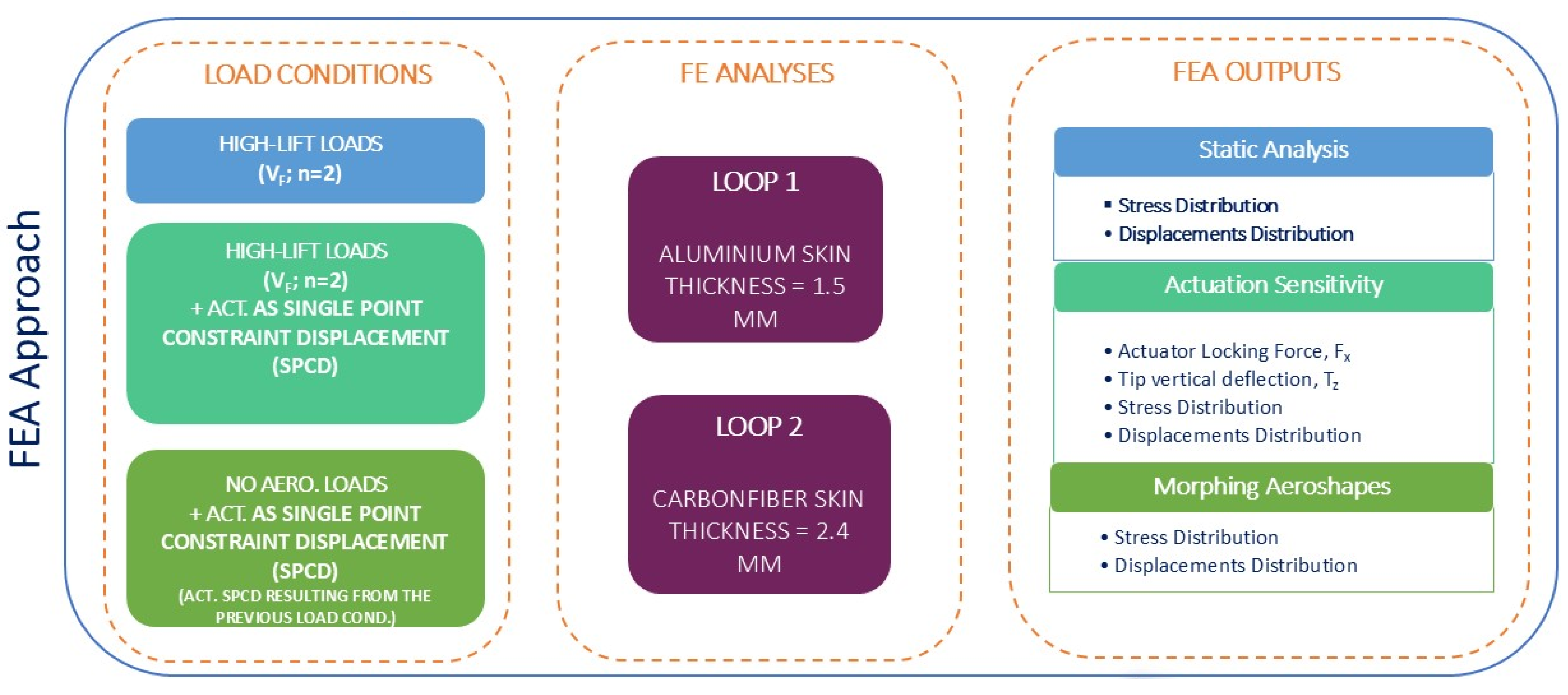
3.3.1. C1 FEM Description

The C1 FEM model accounts for 9912 elements and 10148 nodes. In particular:
The truss ribs have been modeled with beam element properties in aluminum material, with a constant cross-section of 2 × 1 cm.
Shell element properties were used to identify the skin.
In such a model, the most critical elements are represented by the internal beams and mainly by their mutual connections. Thus, a size of 1 mm per element was chosen as the best compromise between the stress distribution and the computational cost of the model.
Two iterations of finite element method (FEM) analyses were conducted, differing in terms of material composition and skin thickness. Specifically, these iterations were characterized as follows:
Loop 1: Utilized aluminum as the material, with a uniform skin thickness of 1.5 mm.
Loop 2: Employed a carbon fiber laminate with a uniform skin thickness of 2.4 mm.
The link between the skin and the ribs has been modeled through Multi Point Constraints (MPCs) rigid elements.
A schematization of the C1 FEM is shown in Figure 8: the beam elements are depicted in white; the shell elements, in yellow and the MPCs in purple.

3.3.2. C2 FEM Description

For the C2 configuration, a preliminary FEM model fully based on beam-like elements was conceived to be suitable for a genetic optimization design, aimed to simplify the architecture and to reduce the number of actuators. The geometrical optimization design parameters accounted for within the model were the thickness of the upper and lower skin, the vertical web and the x-element thickness. Such a FEM coarse model, generated for flexibility verification purposes, was adopted, being a good compromise between the preliminary results to be investigated (displacements and stress distributions) and the computational effort.
All the 1-D elements had aluminum as a material, with the following properties:
  • E = 7.00 × 10¹⁰ N/m2
  • Poisson Ratio = 0.320
  • G = 2.65 × 10¹⁰ N/m2
  • ρ = 2780 kg/m3
Due to the number of parameters characterizing the C2 layout, a genetic approach was adopted to identify a suitable set of parameters, assuring the maximum fitting level of the target morphed shape compliant with the stress absorption capability of the structure. The optimization parameters illustrated in Figure 9 and summarised in Table 1 were considered for the optimization process:
A schematization of the C2 FEM resulting from a first genetic optimization has been reported in Figure 10. In this case, the contraction of the actuation systems induces the deformation of the x-element, ensuring the morphed-down activation of the MF (Figure 11).

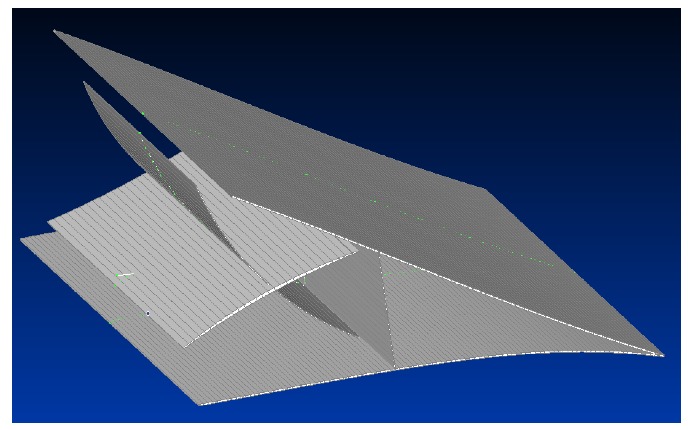
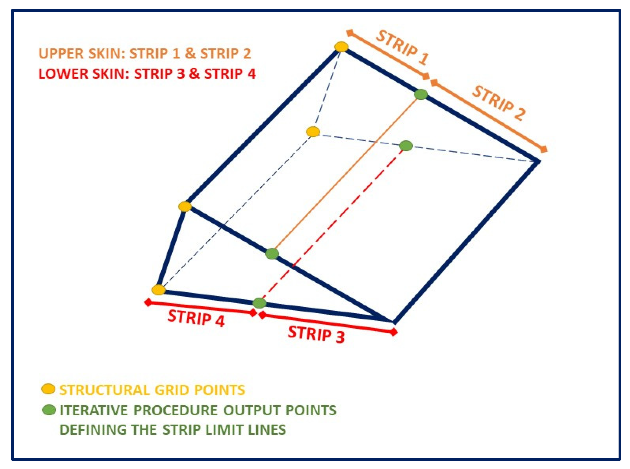
3.4. Aero-Structural Mesh Matching

After the identification of the high-lift load condition for the design, to perform preliminary FEM analyses, the next step was to extract the loads acting only on the MF region, starting from the ones referred to the whole airfoil profile, described in Section 3.1, Figure 12. This step required a matching between the aerodynamic mesh, referred to as a local reference system, and the structural mesh instead, referred to as the global reference coordinate system. Aerostructural matching was performed through an iterative procedure based on the minimization of the root mean square error in the position of the grid points. The output of such a procedure was the final position of the structural grids as in Figure 13, used to define four strips (two for the upper skin and two for the lower skin) where calculating the pressure loads distribution, then applied in the Finite Element Analysis (FEA).

3.5. Finite Element Analyses and Optimization Results

3.5.1. C1 FEA and Results

Two loops of FEA were considered, which were different from each other in terms of used materials and thickness of the skin. In detail:
Loop 1: aluminum skin with a constant thickness of 1.5 mm.
Loop 2: carbon fiber skin, with a proper lay-up and a constant thickness of 2.4 mm.
Each loop was investigated under three load conditions:
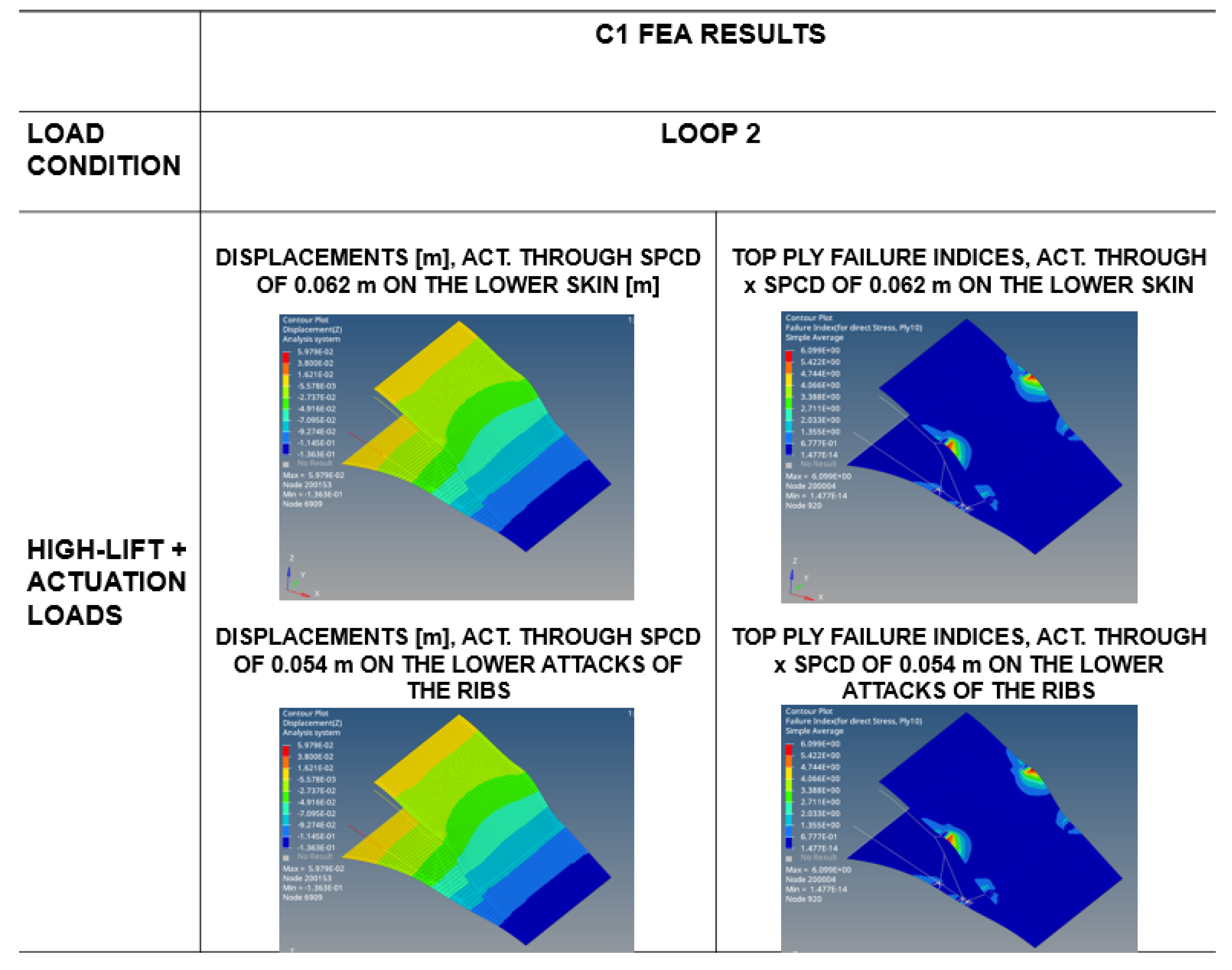
High-lift flapped condition is used to perform static analyses in order to obtain stress/strain and displacement distribution along the MF.
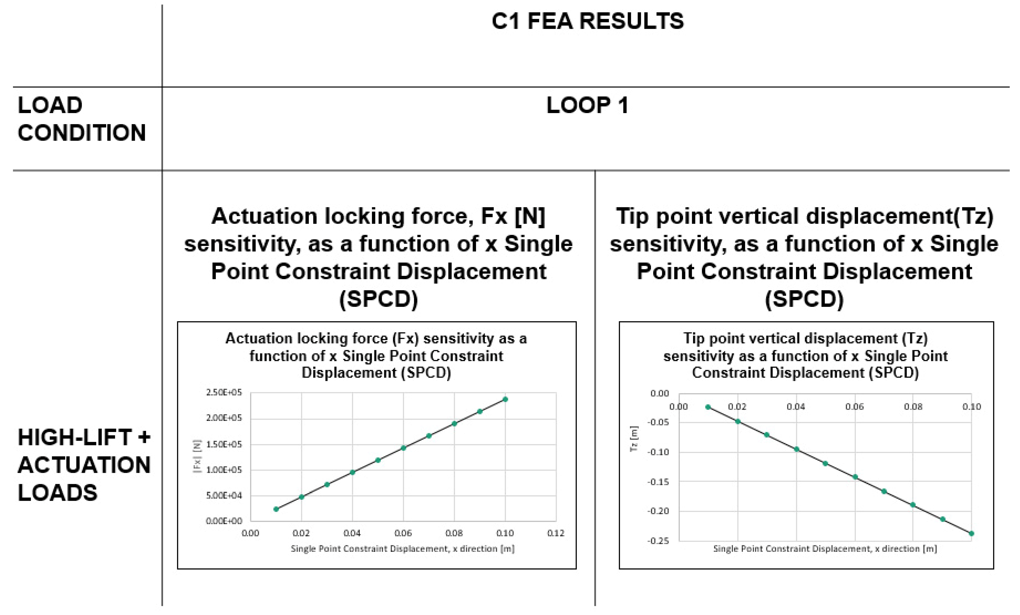
High-lift flapped conditions combined with actuation loads are used to perform an actuation sensitivity analysis.
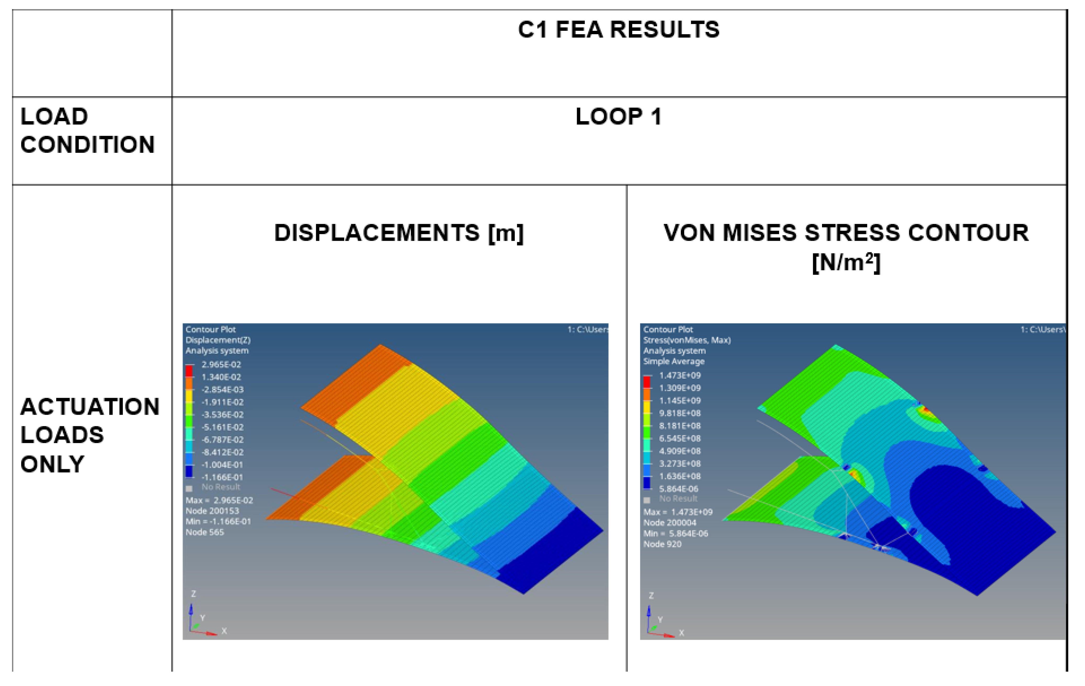
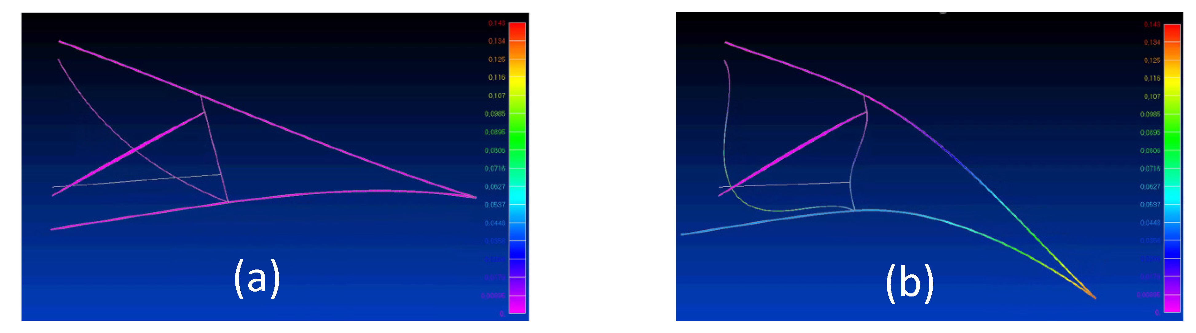
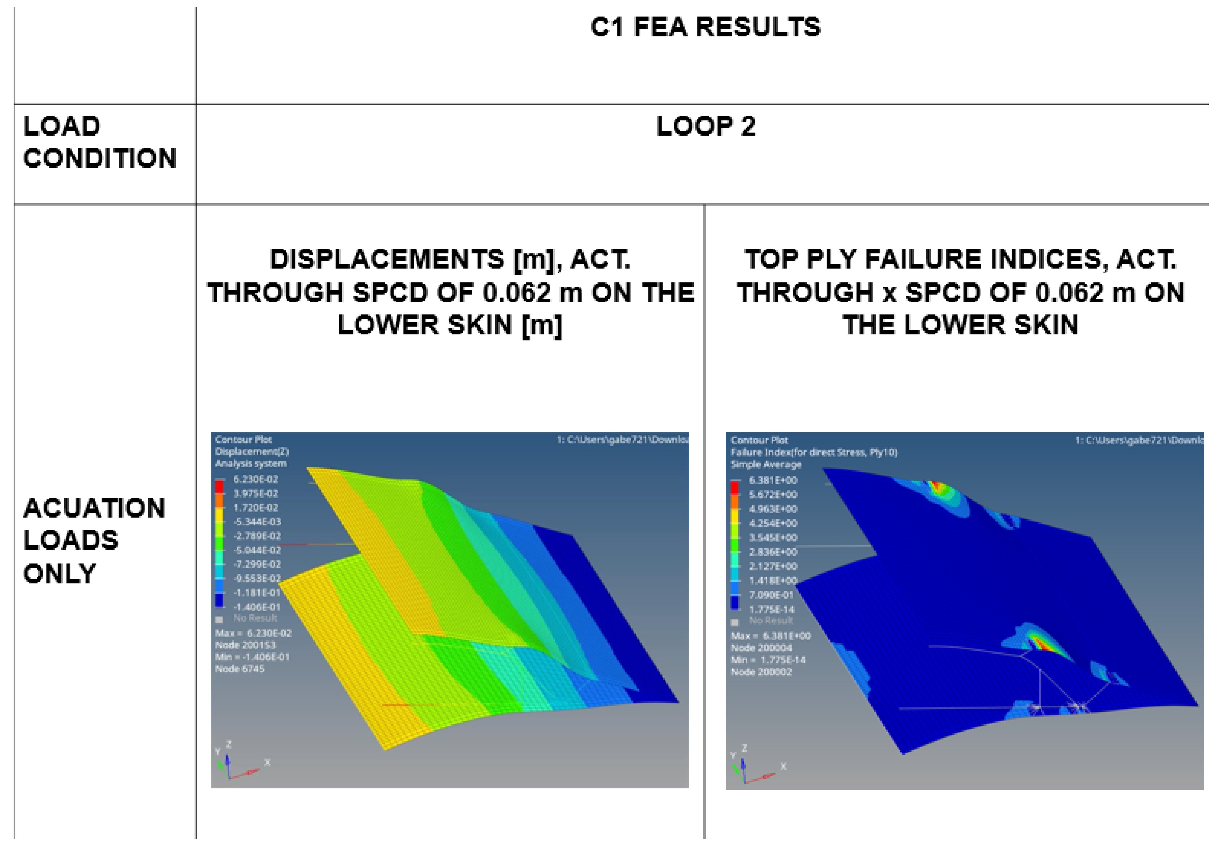
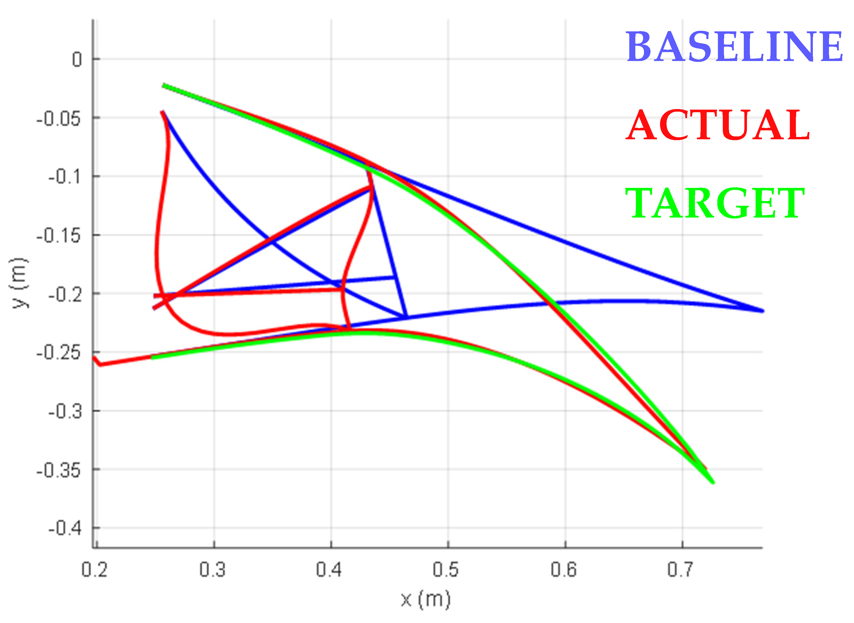
Actuation loads in the absence of aerodynamic loads are used to obtain the morphing aeroshape of the MF.
A scheme of the FEA approach followed for the C1 configuration is depicted in Figure 14.
In terms of boundary conditions, for the upper skin, a fixed constraint was introduced to simulate the attachment area between the morphing flap and the wing box; for the lower skin, an axial carriage was used to model the sliding motion of that structural part in the chordwise direction.
The results gained for the loop 1 have been reported in Figure 15, Figure 16 and Figure 17; the ones relative to the loop 2 have been summarized in Figure 18, Figure 19 and Figure 20.
More in detail, Figure 15 presents static analysis results depicting displacement (left) and Von Mises stress (right) contours obtained during Loop 1 under high lift loading conditions (aerodynamic loads at the VF speed) by accounting for a skin in aluminum with a constant thickness of 1.5 mm. The displacement color map indicates a vertical deflection of 3.29 × 10⁻⁵ m at the MF tip, which remains significantly below the Tz target value due to high structural stiffness. Additionally, without actuation forces, the upper skin interface strip adjacent to the wing box (highlighted in orange in Figure 15) exhibits the highest stress concentration. This is attributed to the localized fixed constraints in this region.
The actuation system’s trade-off analysis involved simulating its performance using Single Point Constraint Displacement (SPCD). Displacements were applied either to:
The middle node of the lower skin.
Both lower rib attachment points.
By systematically varying the SPCD magnitude within a practical operational range, researchers recorded the actuation locking force (Fx) and the vertical deflection at the morphing flap tip (Tz). A displacement of about 0.06 m (SPCD) produced a -0.15 m vertical deflection (Tz) at the MF tip. This configuration fully achieved the target deflection with an actuation locking force of 1.5 × 10⁵ N, as illustrated in Figure 16.
In the final phase of Loop 1 FEA, aerodynamic loads were excluded to isolate the MF morphing mechanism’s performance under actuation loads alone. These actuation loads corresponded to the previously determined SPCD value of ~0.06 m (refer to Figure 16). Displacements and Von Mises stress distributions were calculated to assess the actuation system’s impact on morphing capabilities.
Figure 17 shows an achieved downward tip displacement (Tz) of -0.016 m. Instead, in terms of stress distribution, localized stress peaks (~1.47 GPa) occurred at rigid interfaces between compliant ribs and the upper skin. The safety margin is calculated as the ratio of the aluminum’s allowable tensile strength (71 GPa) to the observed maximum Von Mises maximum stress (1.47 GPa), yielding a value significantly greater than 1. This confirms the design’s structural integrity under actuation-driven morphing, with stress concentrations confined to expected high-stiffness junctions.
To evaluate the structural behavior of the MF using a different material, a second finite element analysis (FEA) loop, referred to as Loop 2, was conducted by applying the same methodology as in Loop 1. A 10-ply carbon-fiber lay-up was chosen, featuring a consistent skin thickness of 2.4 mm.
Figure 18 presents the FEA results for the structure under aerodynamic loads in high-lift configurations. The displacement distribution (shown on the left) differs from that depicted in Figure 15; however, the MF still demonstrates rigidity, with displacement magnitudes around 10−4 m when subjected solely to aerodynamic loads. Due to the composite material properties, the distribution of top ply failure indices is illustrated on the right in the same figure, revealing peaks exceeding 1 at the connections between ribs and skin.
Additional sensitivity analysis was conducted by evaluating the variations in displacements and the distribution of failure indices through the actuation of the lower skin and the lower edges of the ribs. The findings are illustrated in Figure 19, which indicates the following:
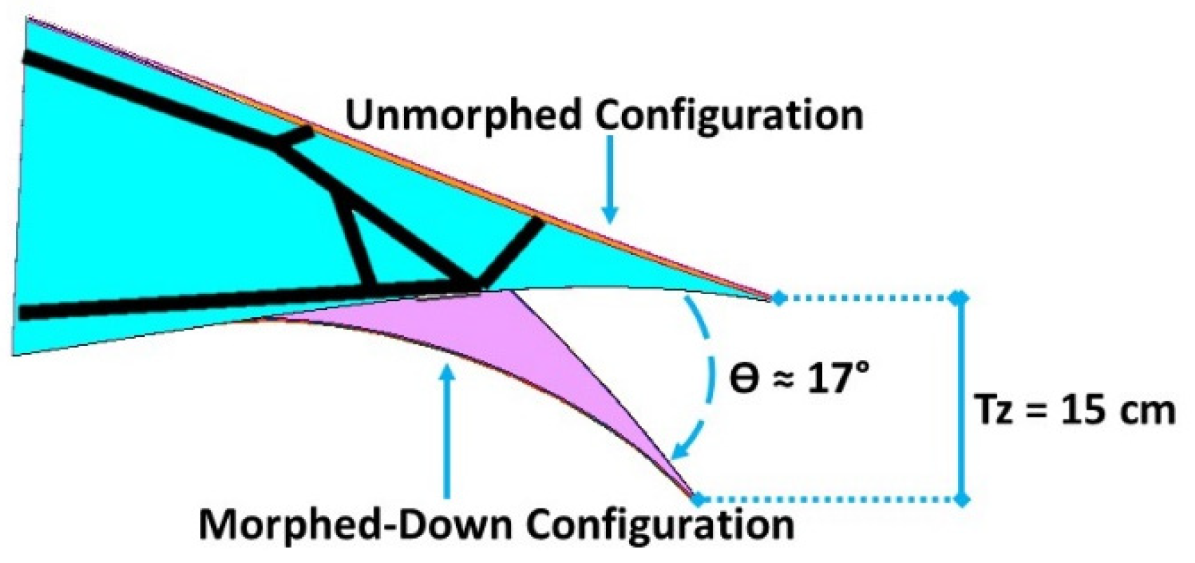
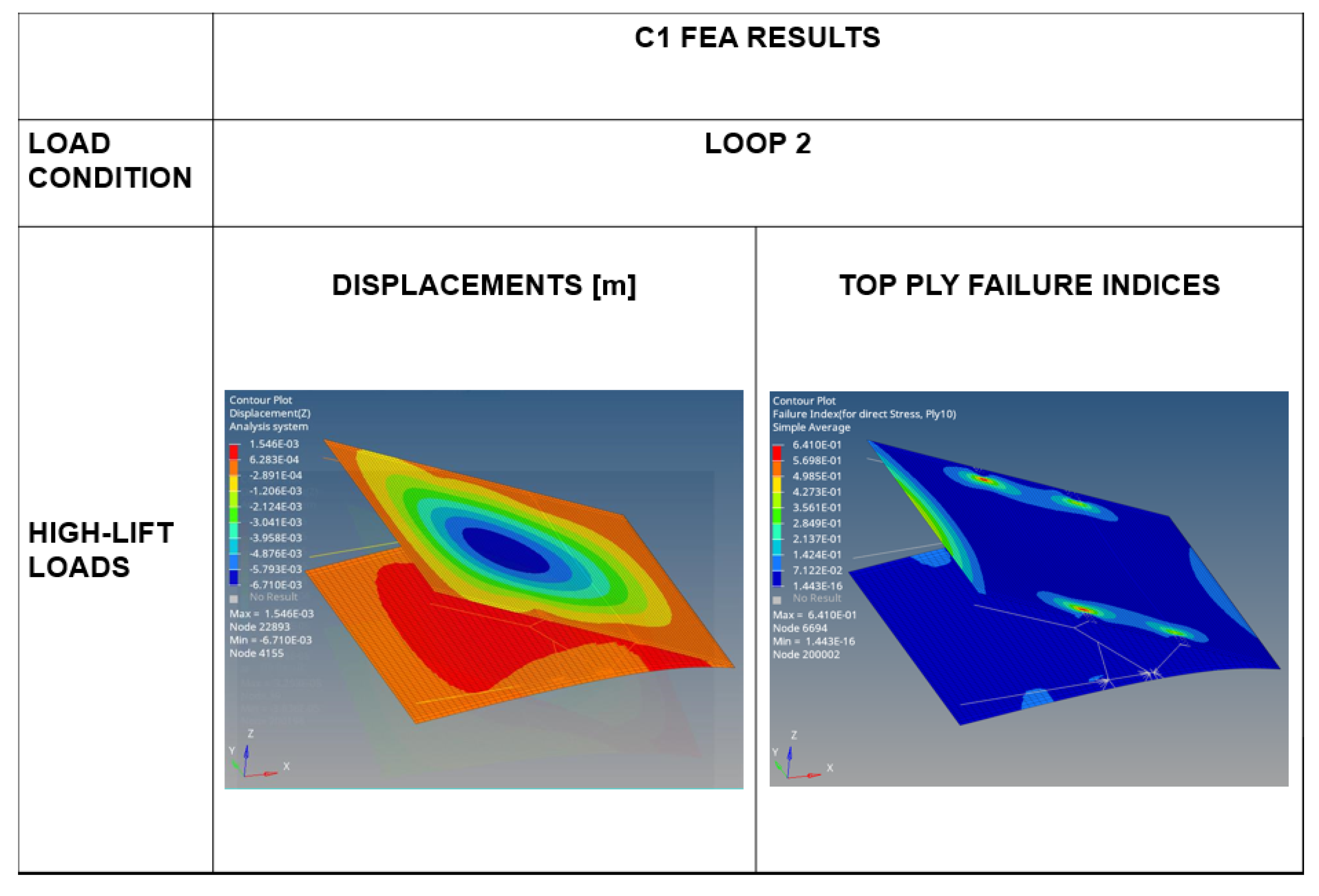
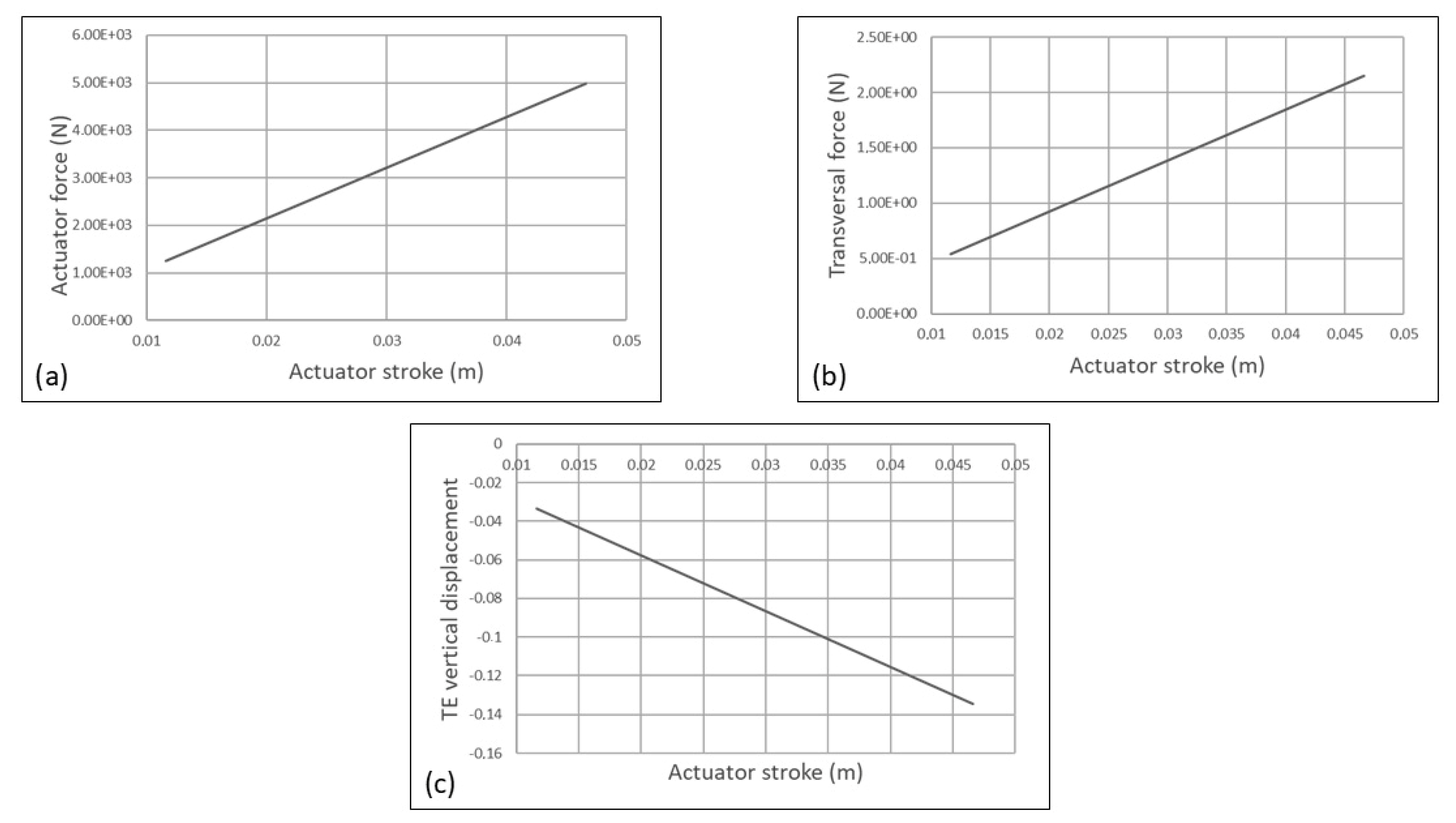
When the lower skin is displaced by 0.062 m, the vertical deflection at the downward tip is approximately 1.4 × 10⁻¹ m, which is very close to the target Tz value. The failure indices for the top ply again reveal peaks at the junctions between the skin and the ribs.
Actuating the lower edges of the ribs by 0.054 m yields Tz results of around 1.5 × 10⁻¹ m, with a similar distribution of top ply failure indices as observed in the previous scenario.
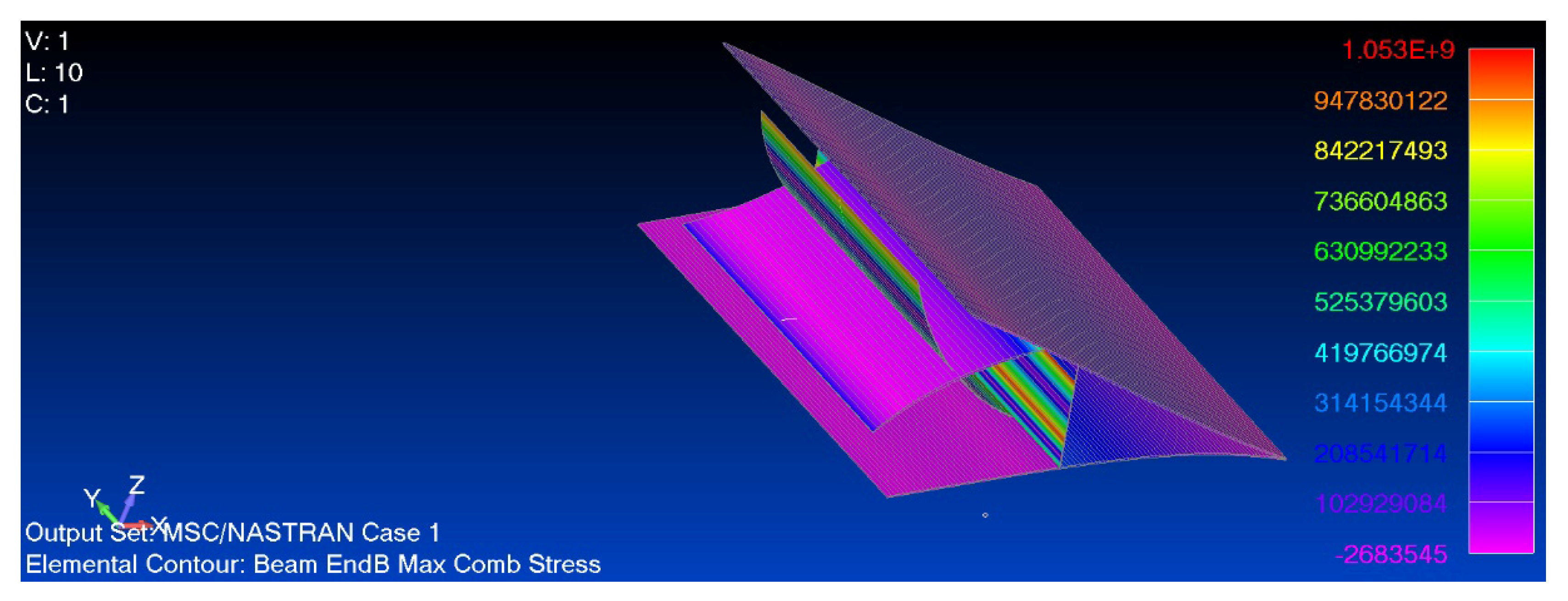
In both cases analyzed, the ribs emerge as the most stressed structural components, highlighting the necessity for optimization in their design.
Final Finite Element Analyses (FEA) were conducted solely under the influence of actuation loads applied to the lower skin, aiming to gather data on displacements and the distribution of top ply failure indices. The findings are illustrated in Figure 20: while the vertical deflection at the downward tip closely aligns with the target value, the resulting morphed shape appears to be discontinuous.
All preliminary results for the C1 configuration indicate that this architecture can meet the Tz requirement with appropriate actuation on the lower skin and lower rib attachments. However, an optimized design is necessary to achieve the desired continuous morphing shape.

3.5.2. C2 FEA and Results

The C2 FEM model was used to perform static analyses under the high-lift flapped condition (Figure 21) shows the overlapping among the baseline (blue curve), the actuated morphed down (red curve), and the target morphed shapes (green curve).
Static analyzed results showed local stress spikes, as shown in Figure 22, due to local gradient effects. This aspect suggested the implementation of more refined models to assess the most critical regions.
Furthermore, an actuation sensitivity analysis was executed to collect trends in terms of actuator locking force, actuator transversal force and downward tip vertical displacement as functions of the actuator stroke, as reported in Figure 23. The most important outcome was that the order of magnitude of the actuation locking force is 103 N, sensibly lower with respect to the C1 corresponding value.

4. Conclusions

In the EU HERWINGT project, one of the objectives deals with the development and the demonstration of high-lift system technology through the combined employment of a morphing droop nose and trailing edge flap for a strut-braced high-aspect-ratio wing suitable for the next-generation Hybrid Electric Regional Aircraft (HERA).
CIRA was involved in the demonstration and the validation of the full-scale MF concept, which is to be integrated within a single bay assembly (DEMO) with a limited span (0.5 m) for functional tests. To achieve that, the authors followed a trade-off approach devoted to the identification of the conceptual design of the morphing flap device.
In this work, the trade-off conceptual design of a compliant morphing flap has been considered by analyzing two configurations, namely C1 and C2, which are different in terms of structural layout (truss-rib VS x-rib layout). Each of them was investigated by considering static behavior (stress-strain and displacement distribution), morphed shapes (actual VS target), and actuation systems.
The C1 results suggested that the external actuation system is a good solution to activate the lower skin, thus enabling the morphed-down activation, but the presence of stress peaks on the ribs encourages optimization of the stiffness distribution of the truss elements. Moreover, the actuation locking force needed to move the assembly resulted in two orders of magnitude higher if compared to the C2 value. In addition, although the downward tip vertical deflection is reachable in all the simulated cases, it is not possible to affirm the same for the target morphed shape.
On the other hand, the C2 results showed that the presence of a vertical web is a good solution to make the morphed shape achievable. In opposition, the employment of an internal actuation system, directly acting on the x-rib elements, causes high peak stresses to be avoided.
All the configurations’ analysis results permitted the underlining of structural criticalities to be overcome under dedicated design considerations.
In conclusion, by accounting for all these preliminary design aspects, the comparison between C1 and C2 suggested that the best design solution could be the one including the lesson learned resulting from the two cases.

Author Contributions

Conceptualization, M.C.N., S.A. and B.G., methodology, S.A. and I.D.; formal analysis, M.C.N. and B.G.; validation, M.C.N. and S.A.; investigation, M.C.N. and S.A.; data curation, S.A., B.G. and M.C.N.; writing—original draft preparation, M.C.N.; writing—review and editing, S.A., I.D. and A.C.; supervision, A.C. and S.A. All authors have read and agreed to the published version of the manuscript.

Funding

This research was funded by Clean Aviation Joint Undertaking under the European Union’s Horizon Europe research and innovation program under grant agreement ID 101102010 (https://doi.org/10.3030/101102010, accessed on 9 February 2025).

Institutional Review Board Statement

Not applicable.

Informed Consent Statement

Not applicable.

Data Availability Statement

Dataset available on reasonable request to the authors; final decision is under the consortium HERWINGT.

Acknowledgments

This study is part of the Hybrid Electric Regional Wing Integration Novel Green Technologies project (HERWINGT). This project has received funding from the Clean Aviation Joint Undertaking under the European Union’s Horizon Europe research and innovation program under grant agreement ID 101102010 (https://doi.org/10.3030/101102010). Views and opinions expressed are, however those of the author(s) only and do not necessarily reflect those of the European Union or the Clean Aviation Joint Undertaking. Neither the European Union nor the granting authority can be held responsible for them.

Conflicts of Interest

The authors declare no conflicts of interest.

References

  1. Rea, F.; Amoroso, F.; Pecora, R.; Noviello, M.C.; Arena, M. Structural Design of a Multifunctional Morphing Fowler Flap for a Twin-Prop Regional Aircraft. In Proceedings of the Intervento Presentato al Convegno SMASIS 2018—Smart Materials, Adaptive Structures and Intelligent Systems Conference, San Antonio, TX, USA, 110–12 September 2018. Available online: https://hdl.handle.net/11588/724489 (accessed on 13 March 2025).
  2. Li, D.; Zhao, S.; Da Ronch, A.; Xiang, J.; Drofelnik, J.; Li, Y.; Zhang, L.; Wu, Y.; Kintscher, M.; Monner, H.P.; et al. A review of modelling and analysis of morphing wings. Prog. Aerosp. Sci. 2018, 100, 46–62. [Google Scholar]
  3. Smith, J.; Johnson, K. Aerodynamic Performance of Morphing Wings. Appl. Sci. 2022, 12, 1234–1245. [Google Scholar]
  4. Doe, J. Morphing Wing Technologies; Springer: Berlin, Germany, 2020; pp. 10–20. [Google Scholar]
  5. Lin, T.; Pecora, R.; Ciliberti, D.; Xia, W.; Hu, S. Aerodynamic optimization of an adaptive flap for next-generation green aircraft. Chin. J. Aeronaut. 2024, 37, 100–122. [Google Scholar] [CrossRef]
  6. Ameduri, S.; Concilio, A. Morphing in Aerospace: Aims, Challenges and Current Showstoppers; Italian Aerospace Research Centre: Capua, Italy, 2020; Available online: https://www.cira.it/it/Pubblicazioni/Lecture%20on%20adaptive%20structures%20v5.pdf (accessed on 6 January 2020).
  7. Kabganian, M.; Hashemi, S.M. Towards Design Optimization of Compliant Mechanisms: A Hybrid Pseudo-Rigid-Body Model–Finite Element Method Approach and an Accurate Empirical Compliance Equation for Circular Flexure Hinges. Biomimetics 2024, 9, 471. [Google Scholar] [CrossRef] [PubMed]
  8. Pecora, R.; Amoroso, F.; Arena, M.; Noviello, M.C.; Rea, F. Experimental validation of a true-scale morphing flap for large civil aircraft applications. In Proceedings of the SPIE; SPIE: Bellingham, WA, USA, 2017; p. 101660L. [Google Scholar] [CrossRef]
  9. Esposito, M.; Roy, R.; Surace, C.; Gherlone, M. Hybrid Shell-Beam Inverse Finite Element Method for the Shape Sensing of Stiffened Thin-Walled Structures: Formulation and Experimental Validation on a Composite Wing-Shaped Panel. Sensors 2023, 23, 5962. [Google Scholar] [CrossRef] [PubMed]
  10. Smith, A.M.O. High-lift aerodynamics. J. Aircr. 1975, 12, 501–530. [Google Scholar] [CrossRef]
  11. Strüber, H. The aerodynamic design of the A350 XWB-900 high lift system. In Proceedings of the 29th International Congress of the Aeronautical Sciences, St. Petersburg, Russia, 7–12 September 2014. [Google Scholar]
  12. Cavalieri, V.; De Gaspari, A.; Ricci, S. Optimization of compliant adaptive structures in the design of a morphing droop nose. Smart Mater. Struct. 2020, 29, 075020. [Google Scholar] [CrossRef]
  13. Monner, H.P.; Breitbach, E.; Bein, T.; Hanselka, H. Design aspects of the adaptive wing–the elastic trailing edge and the local spoiler bump. Aeronaut. J. 2000, 104, 89–95. [Google Scholar] [CrossRef]
  14. Kintscher, M.; Monner, H.P.; Heintze, O. Experimental testing of a smart leading edge high lift device for commercial transportation aircrafts. In Proceedings of the 27th International Congress of the Aeronautical Sciences (ICAS), Nice, France, 19–24 September 2010. [Google Scholar]
  15. Woelcken, P.C.; Papadopoulos, M. (Eds.) Smart Intelligent Aircraft Structures (SARISTU)—Proceedings of the Final Project Conference; Springer International Publishing: Cham, Switzerland, 2016; ISBN 978-3-319-22413-8. [Google Scholar]
  16. Concilio, A.; Dimino, I.; Pecora, R. SARISTU: Adaptive Trailing Edge Device (ATED) design process review. Chin. J. Aeronaut. 2020, 34, 187–210. [Google Scholar]
  17. Concilio, A.; Dimino, I.; Lecce, L. (Eds.) Morphing Wing Technologies for Large Commercial Aircraft and Helicopter Scenario; Butterworth-Heinemann: Kidlington, UK, 2018; ISBN 978-0-08-100964-2. [Google Scholar]
  18. Kota, S.; Osborn, R.; Ervin, G.; Maric, D.; Flick, P.; Paul, D. Mission Adaptive Compliant Wing–Design, Fabrication and Flight Test; RTO Applied Vehicle Technology Panel (AVT) Symposium; NATO Science and Technology Organization: Paris, France, 2009. [Google Scholar]
  19. Hetrick, J.A.; Kota, S. An energy formulation for parametric size and shape optimization of compliant mechanisms. J. Mech. Des. 1999, 121, 229–234. [Google Scholar] [CrossRef]
  20. Kerr-Jia, L.; Kota, S. Topology and dimensional synthesis of compliant mechanisms using discrete optimization. J. Mech. Des. 2006, 128, 1080–1091. [Google Scholar]
  21. Ameduri, S.; Galasso, B.; Noviello, M.C.; Dimino, I.; Concilio, A.; Catalano, P.; D’Aniello, F.A.; Carossa, G.M.; Pinazo, L.; Derry, J.; et al. Design and optimization of a compliant morphing trailing edge for high-lift generation. Appl. Sci. 2025, 15, 2529. [Google Scholar] [CrossRef]
  22. Catalano, P.; Diodati, G.; Lucariello, D.; Vitagliano, P. Aero-structural design of a high-aspect ratio wing. In Proceedings of the AIAA SciTech Forum, Orlando, FL, USA, 8–12 January 2024. [Google Scholar]
  23. Noviello, M.C.; Dimino, I.; Ameduri, S.; Concilio, A. Conceptual Design and Topology Optimization of a Compliant Morphing Flap for the Next Generation Hybrid-Electric Regional Aircraft. In Proceedings of the 34th ICAS Conference, Florence, Italy, 9–13 September 2024. [Google Scholar]
  24. De Gaspari, A.; Cavalieri, V.; Ricci, S. Experimental and Performance Validation of a Full-Scale Morphing Droop Nose Design Based on Composite Compliant Structures. Compos. Struct. 2024, 348, 118502. [Google Scholar] [CrossRef]
  25. Cavalieri, V.; De Gaspari, A.; Ricci, S. Aero-Structural Design Optimization of a Morphing Aileron Considering Actuation Aspects. In Proceedings of the AIAA SCITECH 2024 Forum, Clean Aviation Special Session: Innovative Aircraft Concepts and Novel Configurations, Orlando, FL, USA, 8–12 January 2024. [Google Scholar] [CrossRef]
  26. De Gaspari, A.; Cavalieri, V.; Corti, M.; Ricci, S. Multi-Objective Design Optimization of a Morphing Aileron for a Hybrid Electric Regional Aircraft. In Proceedings of the 34th ICAS Conference, Florence, Italy, 9–13 September 2024. [Google Scholar]
Figure 1. HERWINGT CIRA activities at the project level, with a focus on the aim of this work.
Applsci 15 03660 g001
Figure 2. CIRA multi-step design approach for the compliant morphing flap.
Applsci 15 03660 g002
Figure 3. Reference wing (HERA) for the MF DEMO design development, with tabular details on the geometrical features.
Applsci 15 03660 g003
Figure 4. 2D Aerodynamic pressure distribution (orange curve) and reference airfoil profile (blue curve) in morphed configuration at VF and load factor = 2.
Applsci 15 03660 g004
Figure 5. Structural requirements for the MF.
Applsci 15 03660 g005
Figure 6. C1 structural layout, with details on the upper skin (a), lower skin, and compliant rib (b).
Applsci 15 03660 g006
Figure 7. C2 system layout.
Applsci 15 03660 g007
Figure 8. C1 MF DEMO FEM. Beam (white), shell (yellow) and rigid (purple) elements.
Applsci 15 03660 g008
Figure 9. Optimization parameters on isometric (a) and lateral view (b).
Applsci 15 03660 g009
Figure 10. C2 FEM corresponds to a first loop of genetic optimization.
Applsci 15 03660 g010
Figure 11. C2 1-D FEM, unmorphed (a) and morphed down (b).
Applsci 15 03660 g011
Figure 12. MF section and related aerodynamic loads.
Applsci 15 03660 g012
Figure 13. Aero-structural matching procedure output schematization.
Applsci 15 03660 g013
Figure 14. C1 FEA approach.
Applsci 15 03660 g014
Figure 15. C1 Loop 1 FEA results, hgh lift loads condition.
Applsci 15 03660 g015
Figure 16. C1 Loop 1 FEA results, High Lift + Actuation Loads.
Applsci 15 03660 g016
Figure 17. C1 Loop 1 FEA results, actuation loads only.
Applsci 15 03660 g017
Figure 18. C1 Loop 2 FEA results, high-hift load condition.
Applsci 15 03660 g018
Figure 19. C1 Loop 2 FEA results, high lift + actuation loads.
Applsci 15 03660 g019
Figure 20. C1 Loop 2 FEA results, actuation loads only.
Applsci 15 03660 g020
Figure 21. C2 Baseline, actual and target shapes.
Applsci 15 03660 g021
Figure 22. C2 FEA results: Von-Mises stress contour map [N/m2].
Applsci 15 03660 g022
Figure 23. (a) Actuator locking force, actuator transversal force, (b) and downward tip vertical displacements, (c) as functions of the actuator stroke [m].
Applsci 15 03660 g023
Table 1. Optimization parameters for C2 design.
ParameterDescriptionRange
p1Fore X-spar connection node (point A)1–87 (top skin nodes between 1 and 100)
p2Fore X-spar connection node (point B)102–188 (top skin nodes between 101 and 200)
p3Location of edge C of the fore X springParametric on dashed segment
p4Location of edge D of the fore X spring
p5Spar thickness1–3 mm
p6Location of edge E of the fore X springParametric on the upper half zone of the web vertical edge
p7Location of edge F of the fore X springParametric on the lower half zone of the web vertical edge
p8The curvature of the BC plate of the X−25–+25 mm
p9Thickness on the middle of the DE plate of the X1–3 mm
p10Thickness on the edges of the DE plate of the X
p11Depth of the edges of the DE plate of the X10–400 mm
p12Depth of the middle of the DE plate of the X
p13The curvature of the DE plate of the X−25–+25 mm
p14Thickness on the middle of the BC plate of the X1–3 mm
p15Thickness on the edges of the BC plate of the X
p16Depth of the edges of the BC plate of the X10–400 mm
p17Depth of the middle of the BC plate of the X
p18Location of hinge G of the actuatorParametric on dashed segment
p19Location of hinge H of the actuatorParametric on the web vertical edge
Disclaimer/Publisher’s Note: The statements, opinions and data contained in all publications are solely those of the individual author(s) and contributor(s) and not of MDPI and/or the editor(s). MDPI and/or the editor(s) disclaim responsibility for any injury to people or property resulting from any ideas, methods, instructions or products referred to in the content.

