

Research on the Coupled Bending–Torsional Flutter Mechanism for Ideal Plate

Abstract
1. Introduction
2. Flutter “Incentive-Feedback” Mechanism Theory
2.1. Torsional Modal Damping and Stiffness
2.2. Vertical Modal Damping and Stiffness
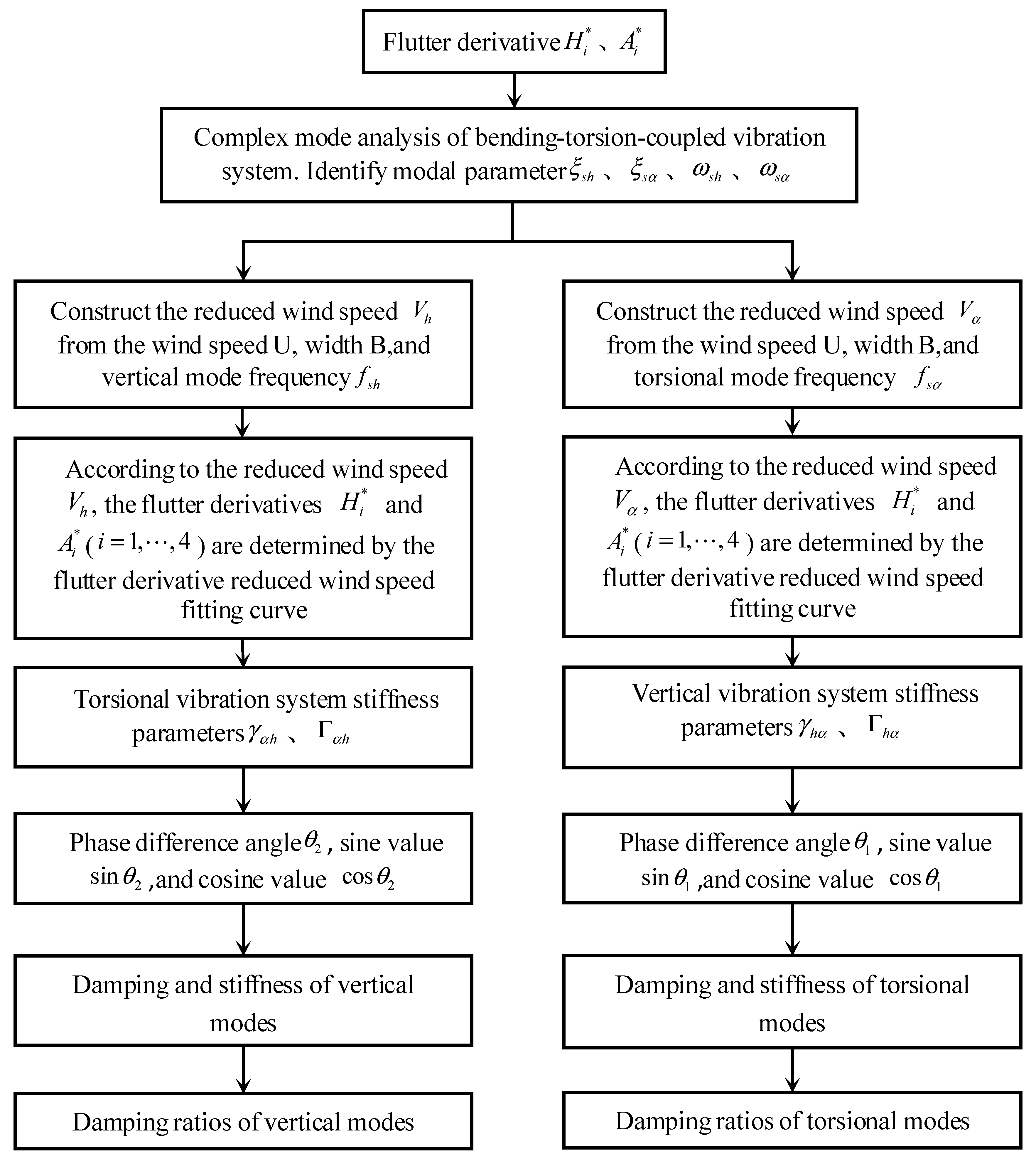
3. Identification Steps for Aerodynamic Damping Based on the “Incentive-Feedback” Mechanism
4. Ideal Flat Plate Flutter Analysis
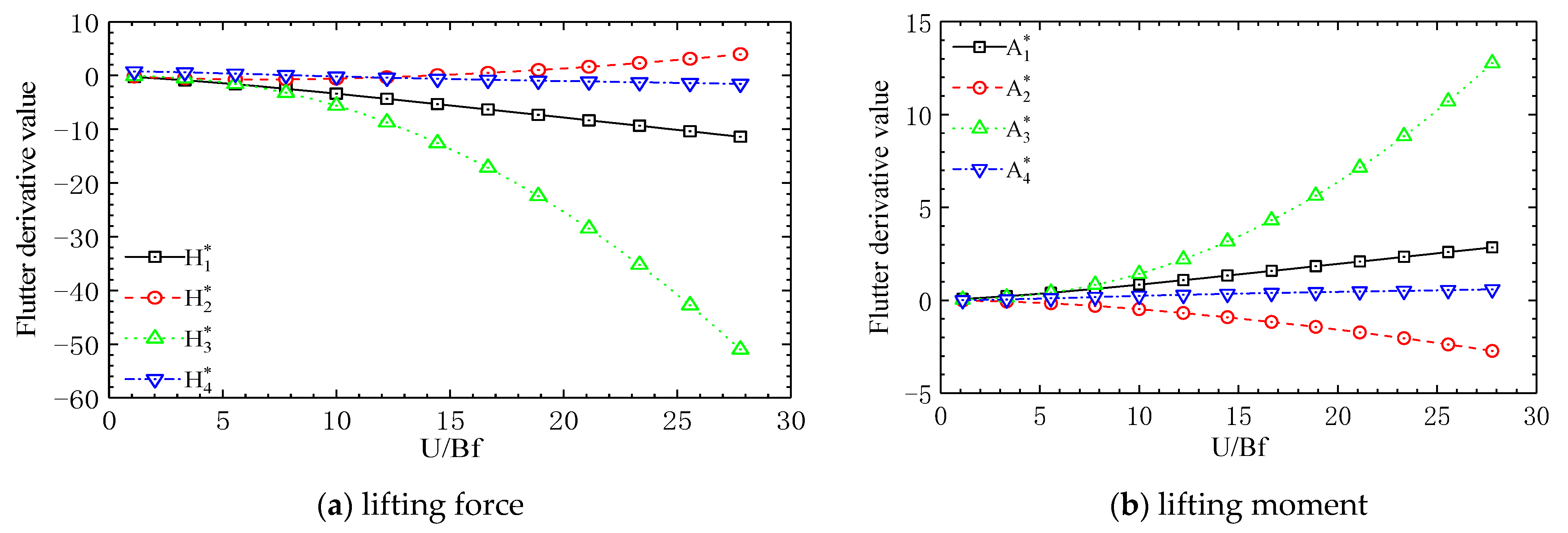
4.1. Ideal Flat Plate Flutter Derivative
4.2. Flutter Critical Wind Speed
4.3. Flutter Frequency
- (1)
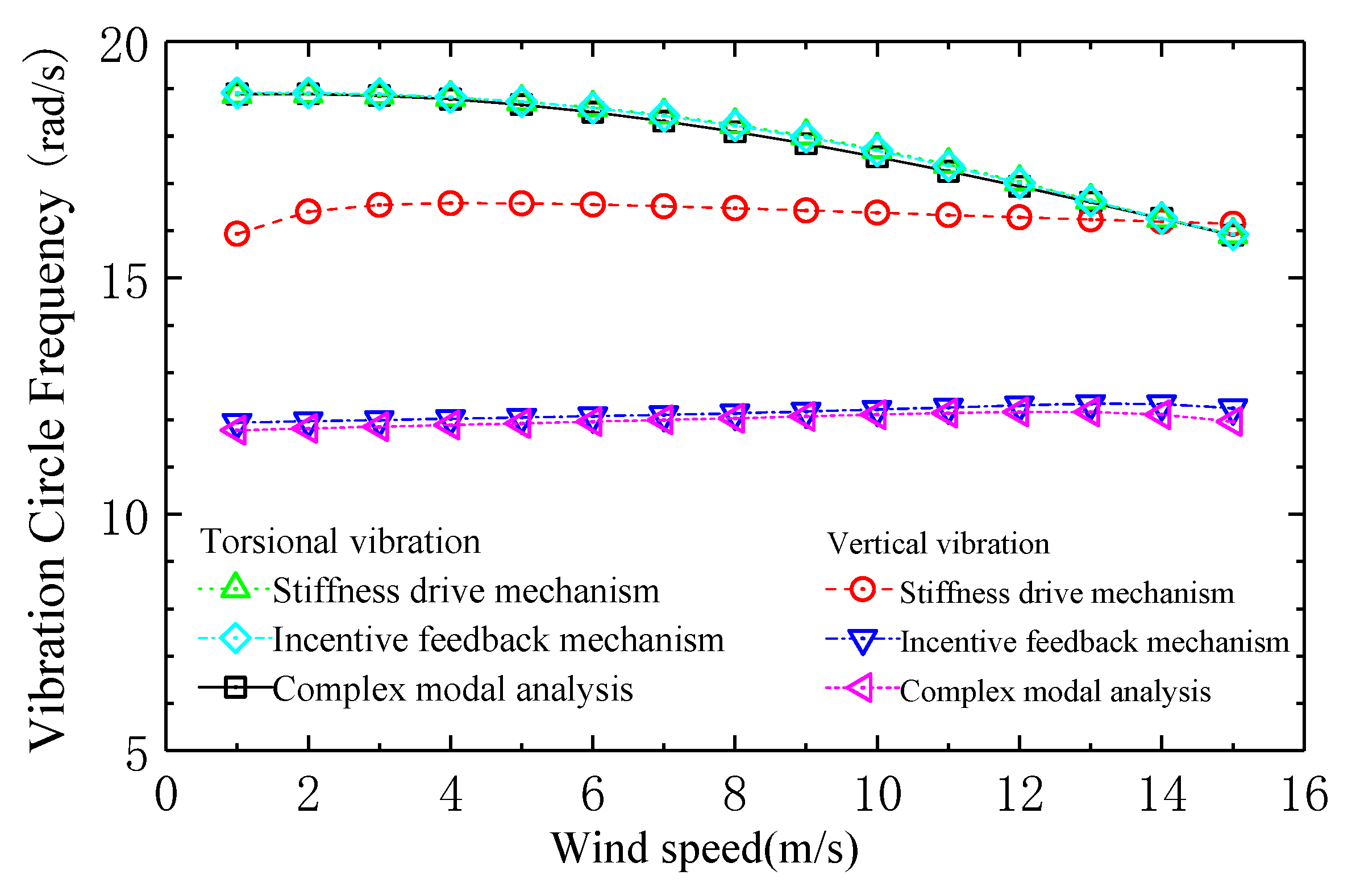
- The vertical and torsional mode frequencies identified by the two theories of “complex mode analysis” and “incentive feedback” mechanism are consistent with each other. The torsional mode frequencies identified by the “stiffness-driven” mechanism theory are consistent with the “complex mode analysis” and “incentive feedback” mechanisms, and the vertical vibration frequency is equal to the torsional vibration frequency in the flutter critical state.
- (2)
- The torsional vibration damping ratio is close to zero at all levels of wind speed, while the vertical vibration damping ratio gradually increases with the increase of wind speed, and is obviously greater than zero. Therefore, the variation curve of the torsional mode frequency with wind speed identified by the “stiffness-driven” mechanism is consistent with the torsional vibration frequency identified by the complex mode analysis and the incentive feedback mechanism, while the vertical mode frequency identified by the “stiffness-driven” mechanism is deviated from the modal frequency identified by the complex mode analysis and the “incentive-feedback” mechanism. However, in the flutter critical state, the damping ratios of vertical and torsional vibrations are zero, which is consistent with the assumption of the “stiffness drive” mechanism, where the vertical and torsional vibration frequencies are the same, and the flutter critical frequency is located on the torsional vibration frequency change curve, indicating that the ideal plate flutter is a bending–torsion-coupled vibration driven by its torsional mode. When the wind speed is greater than the flutter critical wind speed, the torsional mode damping is identified as negative damping and the vertical mode damping is positive by the “complex mode analysis” and “incentive feedback” mechanisms. Therefore, when the wind speed exceeds the flutter critical wind speed, the flutter morphology of the ideal plate is due to the negative damping of the torsional mode.
4.4. Ideal Flat Plate Aerodynamic Damping
- (1)
- The torsional modal damping is mainly derived from terms and , that is, the feedback aerodynamic damping of torsional velocity self-excited aerodynamic damping in the torsional vibration system and the vertical vibration induced by the torsional displacement self-excited lift force in the torsional vibration system, in which the aerodynamic damping of item is positive damping and the aerodynamic damping of item is negative damping, while the intrinsic damping of the torsional vibration system and the aerodynamic damping of other items are significantly smaller than the aerodynamic damping of items and , and their contribution to the total damping of the torsional vibration system is very small.
- (2)
- The vertical modal damping is mainly derived from terms and , that is, the vertical velocity self-excited aerodynamic damping in the vertical vibration system and the pneumatic damping fed back by the torsional vibration induced by the vertical velocity self-excited moment in the vertical vibration system, among which the and terms are both positive damping. However, the intrinsic damping and other aerodynamic damping of the vertical vibration system are significantly smaller than those of and aerodynamic damping, and their contribution to the total damping of the vertical vibration system is small.
- (3)
- When the wind speed exceeds the flutter critical wind speed, the negative aerodynamic damping of the “incentive feedback” torsional displacement of the ideal flat plate leads to the dispersion of its torsional vibration, and its vertical vibration system is forced to disperse due the torsional self-excited lifting force, which leads to the occurrence of the bending–torsional-coupled flutter.
4.5. Function and Function
- (1)
- The function is the aerodynamic damping function of the flutter derivative , and the flutter derivative is positive at the wind speed of 1 m/s, while the wind speed at all other levels is negative, and its value gradually decreases with the increase of wind speed. The function is always negative, and its value gradually increases with increasing wind speed. Therefore, at a wind speed of 1 m/s, is negative, while at all other wind speeds, it is positive, and its value gradually increases with increasing wind speed. It can be seen from this that the trend of depends on the derivative of vibration . Although function has a small impact on the value of , its value is negative, determining that the aerodynamic damping of term is positive damping.
- (2)
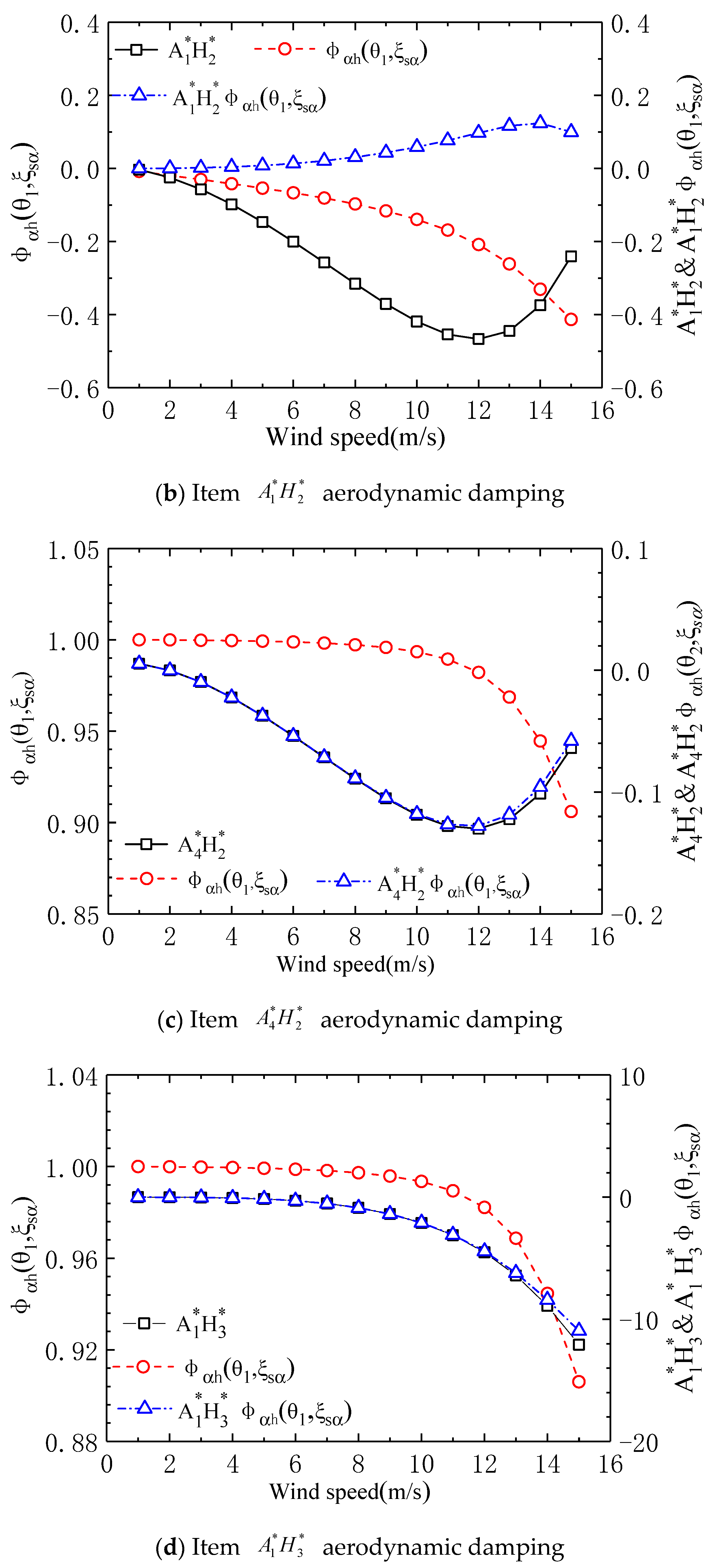
- Function is the aerodynamic damping function of the product , which is always negative in value. Its absolute value gradually increases with increasing wind speed and then rapidly decreases. The value of is always negative, and its absolute value gradually increases with increasing wind speed. Therefore, the aerodynamic damping of is positive damping, and when the wind speed exceeds 12 m/s, the absolute value of function decreases, resulting in a significant decrease in with increasing wind speed.
- (3)
- Function is the aerodynamic damping function of the product , which is always negative in value. Its absolute value increases initially with wind speed and then decreases. As the wind speed increases, decreases. Its value lies between 0.9 and 1.0. Its impact on is minimal, while its value aligns closely with the product of and the flutter derivative .
- (4)
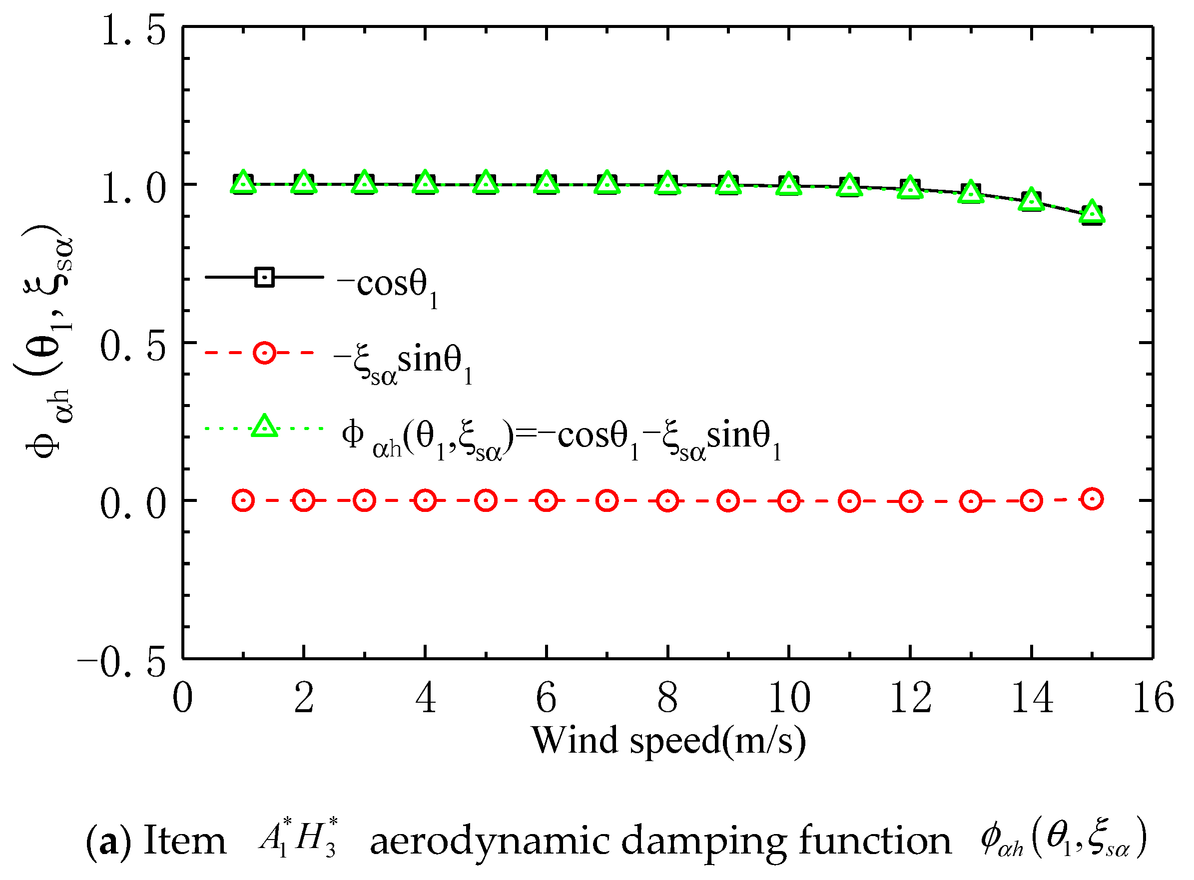
- Function is the aerodynamic damping function of the product , which is always negative in value and gradually decreases with increasing wind speed. decreases with the increase of wind speed, and its value is between 0.9 and 1.0, which has little effect on , and the value of is basically consistent with the value of flutter derivative . The reason why the aerodynamic damping of item appears as negative damping is because the vibration derivatives and have opposite signs, and function is positive.
- (5)
- Function is the aerodynamic damping function of the product , which always maintains a negative value and gradually decreases with increasing wind speed. The value of always remains positive, ranging between 0.0 and 0.44, and gradually increases with wind speed. Therefore, the aerodynamic damping of is negative, and function leads to a significant decrease in the value of relative to the flutter derivative .
- (6)
- It can be seen from (f) in Figure 5 that among the aerodynamic damping of torsional modes, in the aerodynamic damping of and in the aerodynamic damping of term are significantly greater than that of aerodynamic damping , which shows that the aerodynamic damping of flutter torsional mode mainly comes from two aspects: one is the self-excited aerodynamic damping of torsional velocity in the torsional vibration system; the second is the vertical vibration velocity response induced by the torsional displacement lift in the vertical vibration system, and the pneumatic damping in the torsional vibration system is fed back to the torsional vibration system through the vertical velocity self-excited torque.
4.6. Analysis of Function in Torsional Pneumatic Damping
- (1)
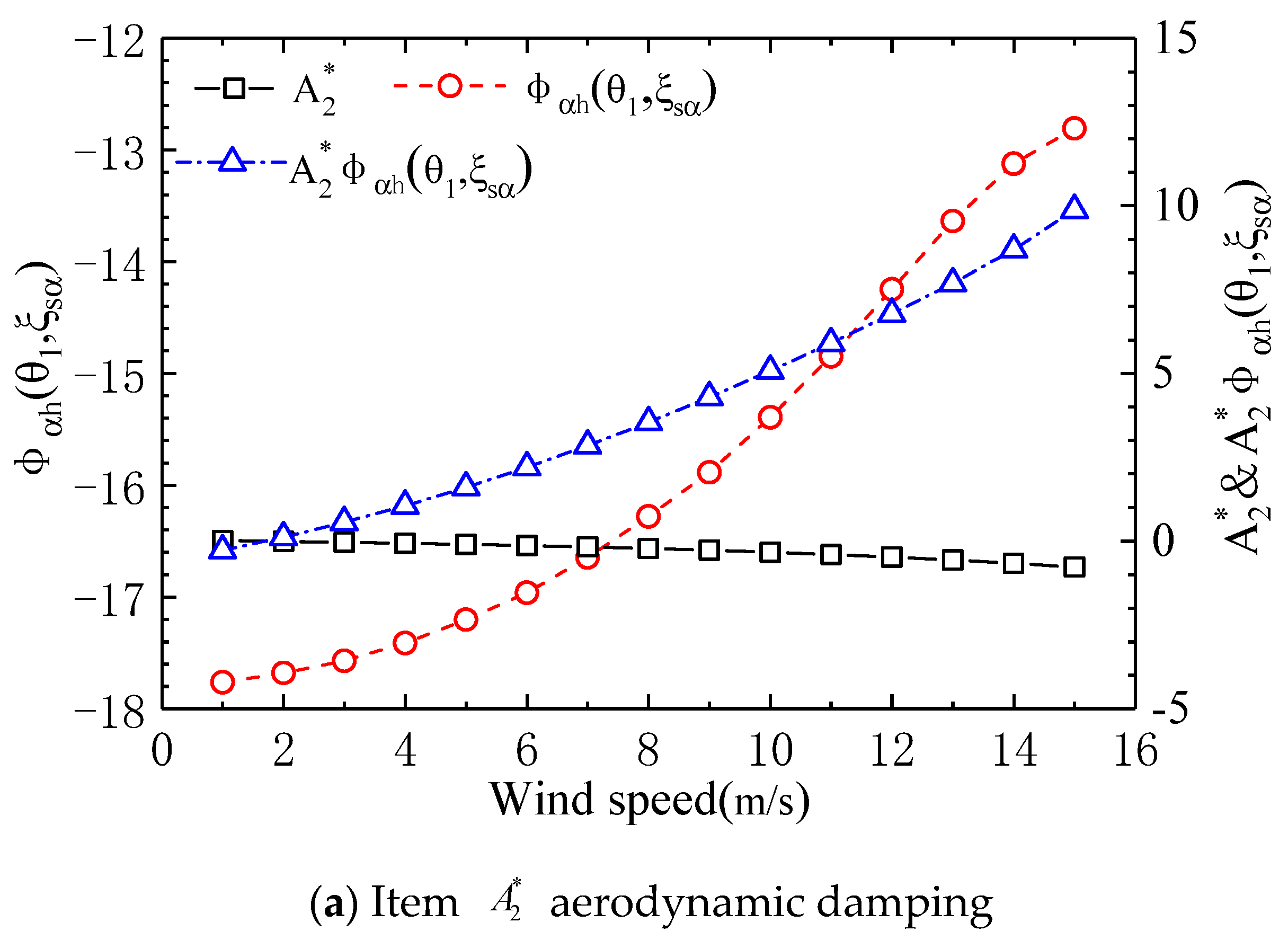
- In the torsional vibration system, the value of in the aerodynamic damping function of term is close to 0, and its contribution to is very small. The value of function is basically equal to , while does not affect the positive or negative value of function .
- (2)
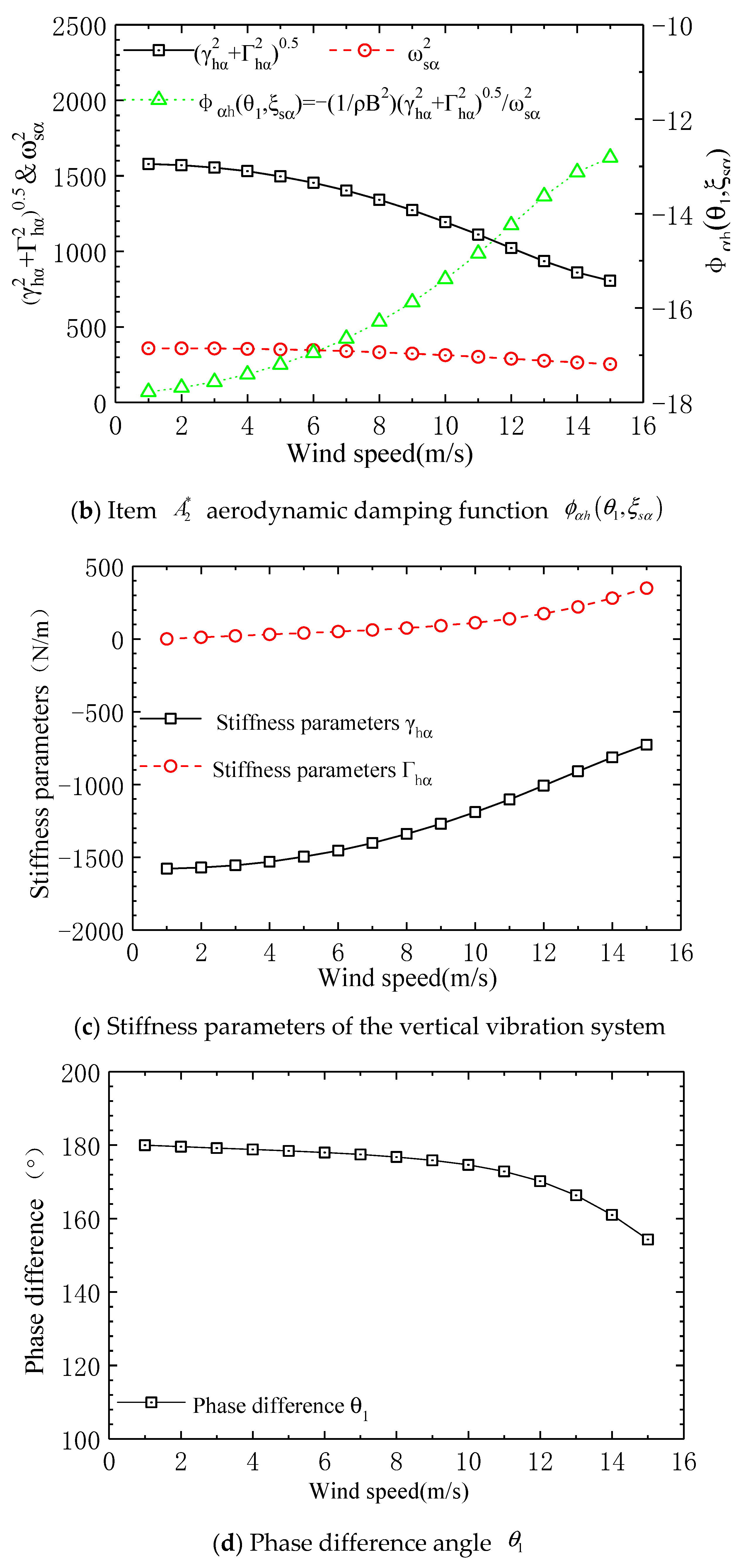
- In the torsional vibration system, the aerodynamic damping function term of term is only related to the stiffness parameter and the torsional mode circle frequency , where and are both positive values, so that is a negative value; then, the aerodynamic damping of term is a positive value.
- (3)
- The phase difference between the lift force reversal and vertical displacement gradually decreases as wind speed increases but it always remains within the range of (90° to 180°), meaning that the cosine function is negative, resulting in a positive value for . Therefore, under the condition that the flutter derivative product is negative, the aerodynamic damping of the torsional vibration system exhibits negative damping.
- (4)
- The value of phase difference being in the interval (90–180°) depends entirely on the parameters of the vertical vibration system and . From the graph, it can be observed that is always negative, while is always positive, so is positive and is negative. Therefore, the phase difference angle must be in the 90° to 180° interval.
4.7. Stiffness Parameter Analysis
- (1)
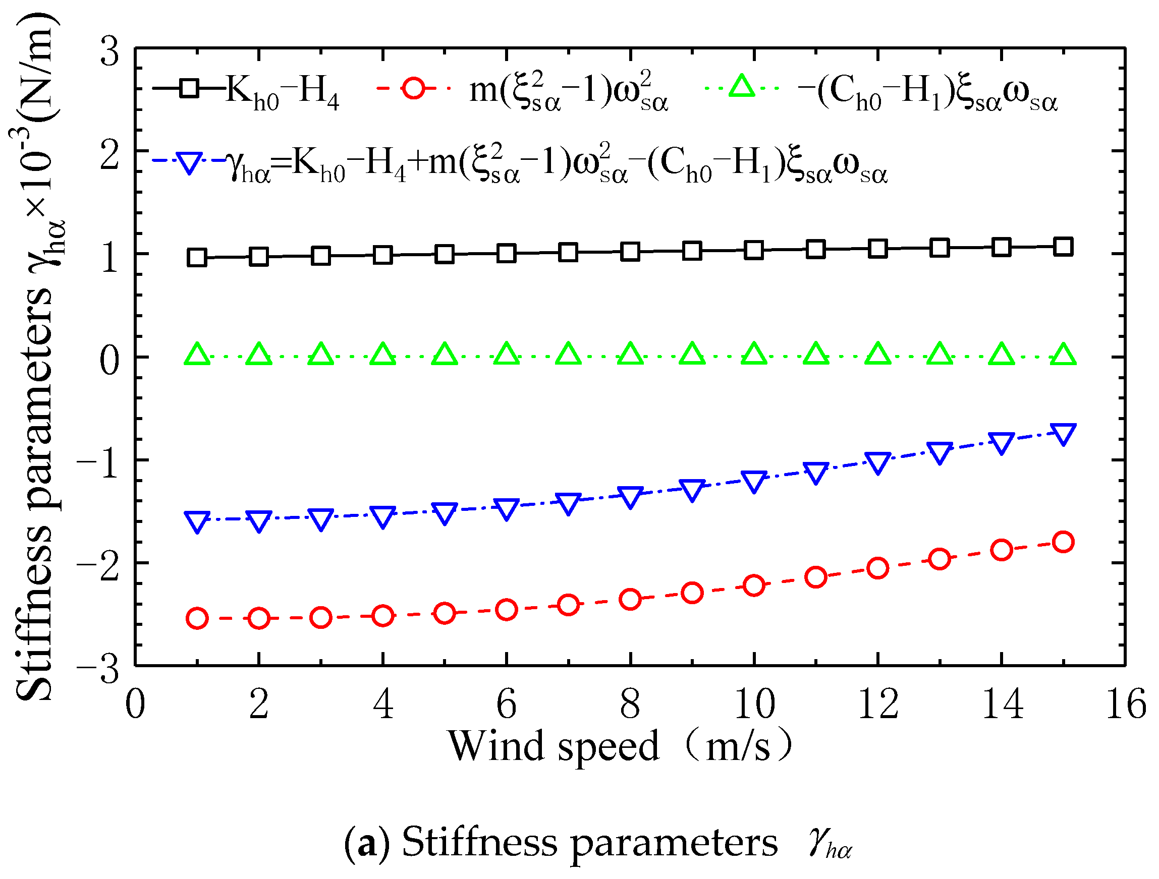
- In the stiffness parameter expression , the value of is close to zero relative to the other two stiffness parameters in . Therefore, the numerical value of stiffness parameter depends on the sum of and . Among them, because the torsional mode damping ratio of square in term is significantly less than 1, the value of this term is approximately equal to , and is the negative stiffness generated by the torsional displacement self-excited force during the excitation of vertical vibration. The stiffness parameter has a negative value because the negative stiffness is significantly greater than the vertical vibration system’s positive stiffness .
- (2)
- In the stiffness parameter expression , is always negative before flutter, and it changes from negative to positive as it approaches the critical flutter wind speed; whereas is always positive, with its value increasing linearly with wind speed , being significantly greater than at all wind speeds, resulting in a positive value for stiffness parameter .
- (3)
- Negative stiffness results in a negative value for stiffness parameter , while positive stiffness leads to a negative value for stiffness parameter . Therefore, the cosine function is negative, causing the phase angle between torsional displacement self-excited lift and vertical displacement response to be in the (90° 180°) interval.
5. Conclusions
- (1)
- The main sources of vertical modal damping in an ideal plate are twofold: firstly, the aerodynamic positive damping induced by vertical velocity self-excitation in the vertical vibration system; secondly, the torsional vibration system, where vertical velocity self-excites a twisting moment, and the twisting displacement self-excites aerodynamic positive damping that feeds back to the vertical vibration system.
- (2)
- The main sources of damping for the ideal flat plate’s torsional mode come from two aspects: firstly, the self-excited aerodynamic positive damping due to torsional velocity in the torsional vibration system; secondly, the vertical displacement self-excites the vertical vibration velocity through lift-induced vertical excitation in the vertical vibration system, and the vertical velocity self-excites the aerodynamic negative damping feedback to the torsional vibration system.
- (3)
- The torsional displacement of the ideal plate produces the aerodynamic negative damping through “incentive-feedback”, which is greater than its torsional velocity and self-excited positive damping, resulting in the divergence of its torsional vibration. Because the self-excited aerodynamic forces are coupled with each other, and the vertical vibration system diverges at the same time under the excitation of torsional self-excited lift, bending–torsional-coupled flutter occurs.
- (4)
- The “incentive feedback mechanism” indicates that in the process of exciting vertical vibrations, the torsional displacement of an ideal flat plate is caused by self-excited lift. The vertical vibration system produces a negative stiffness , significantly greater than the stiffness of the vertical vibration system, resulting in a cosine value of the phase difference between the torsional displacement due to self-excited lift and the vertical vibration displacement response being less than zero. In other words, the phase difference angle between the torsional displacement due to self-excited lift and the vertical vibration displacement response lies in the interval of 90° to 180°. As a result, when the product of flutter derivatives is negative, the torsional displacement generates torsional aerodynamic negative damping through incentive feedback.
- (5)
- This paper further improves the existing theory in the process of modal decoupling through the “excitation-feedback” mechanism. The process of cyclic search frequency is omitted and improves the calculation efficiency.
Author Contributions
Funding
Institutional Review Board Statement
Informed Consent Statement
Data Availability Statement
Conflicts of Interest
References
- Ding, Y.J.; Zhao, L.; Xian, R.; Liu, G.; Xiao, H.; Ge, Y. Aerodynamic stability evolution tendency of suspension bridges with spans from 1000 to 5000 m. Front. Struct. Civ. Eng. 2023, 17, 1465–1476. [Google Scholar] [CrossRef]
- Zhao, L.; Cheng, Y.; Liu, S.Y.; Fang, G.; Cui, W.; Ge, Y. Instantaneous power balance algorithm for flutter critical wind speed prediction of bridge girders. J. Eng. Mech. 2024, 150, 04023120. [Google Scholar]
- Ma, T.T.; Zhao, L.; Shen, X.M.; Ge, Y.-J. Case study of three-dimensional aeroelastic effect on critical flutter wind speed of long-span bridges. J. Wind. Eng. Ind. Aerodyn. 2021, 212, 104614. [Google Scholar]
- Zheng, J.; Fang, G.S.; Wang, Z.L.; Zhao, L.; Ge, Y. Shape optimization of closed-box girder considering dynamic and aerodynamic effects on flutter: A CFD-enabled and Kriging surrogate-based strategy. Eng. Appl. Comput. Fluid Mech. 2023, 17, 2191693. [Google Scholar] [CrossRef]
- Li, K.; Han, Y.; Cai, C.S.; Hu, P.; Li, C. Experimental investigation on post-flutter characteristics of a typical steel-truss suspension bridge deck. J. Wind Eng. Ind. Aerodyn. 2021, 216, 104724. [Google Scholar] [CrossRef]
- Zhang, Z.T.; Wang, Z.X.; Zeng, J.D.; Zhu, L.; Ge, Y. Experimental investigation of post-flutter properties of a suspension bridge with a Π-shape deck section. J. Fluids Struct. 2022, 112, 103592. [Google Scholar]
- Gao, G.Z.; Zhu, L.D.; Li, J.W.; Han, W.; Yao, B. A novel two-degree-of-freedom model of nonlinear self-excited force for coupled flutter instability of bridge decks. J. Sound Vib. 2020, 480, 115406. [Google Scholar]
- Li, K.; Han, Y.; Cai, C.S.; Hu, P.; Qiu, Z. Three-dimensional nonlinear flutter analysis of long-span bridges by multi-mode and full-mode approaches. J. Wind Eng. Ind. Aerodyn. 2023, 242, 105554. [Google Scholar]
- Chu, X.; Cui, W.; Zhao, L.; Cao, S.; Ge, Y. Probabilistic flutter analysis of a long-span bridge in typhoon-prone regions considering climate change and structural deterioration. J. Wind Eng. Ind. Aerodyn. 2021, 215, 104701. [Google Scholar]
- Fang, G.S.; Pang, W.; Zhao, L.; Xu, K.; Cao, S.Y.; Ge, Y.J. Tropical-cyclone-wind-induced flutter failure analysis of long-span bridges. Eng. Fail. Anal. 2022, 132, 105933. [Google Scholar]
- Matsumoto, M.; Daito, Y.; Yoshizumi, F.; Ichikawa, Y.; Yabutani, T. Torsional flutter of bluff bodies. J. Wind Eng. Ind. Aerodyn. 1997, 69–71, 871–882. [Google Scholar]
- Matsumoto, M.; Kobayashi, K.; Niihara, Y.; Shirato, H.; Hamasaki, H. Flutter mechanism and its stabilization on bluff bodies. In Proceedings of the 9th International Conference on Wind Engineering, New Delhi, India, 9–13 January 1995. [Google Scholar]
- Matsumoto, M. Aerodynamic damping of prims. J. Wind. Eng. Ind. Aerodyn. 1996, 59, 159–175. [Google Scholar]
- Matsumoto, M.; Kobayashi, Y.; Shirato, H. The influence of aerodynamic derivatives on flutter. J. Wind. Eng. Ind. Aerodyn. 1996, 60, 227–239. [Google Scholar]
- Matsumoto, M.; Mizuno, K.; Okubo, K.; Ito, Y. Torsional flutter and branch characteristics for 2-D rectangular cylinders. J. Fluids Struct. 2005, 21, 597–608. [Google Scholar]
- Matsumoto, M.; Okubo, K.; Ito, Y.; Matsumiya, H.; Kim, G. The complex branch characteristics of coupled flutter. J. Wind Eng. Ind. Aerodyn. 2008, 96, 1843–1855. [Google Scholar]
- Matsumoto, M.; Matsumiya, H.; Fujiwara, S.; Ito, Y. New consideration on flutter properties based on step-by-step analysis. J. Wind Eng. Ind. Aerodyn. 2010, 98, 429–437. [Google Scholar]
- Xu, F.Y. System Decoupling Approach for 3-DOF Bridge Flutter Analysis. J. Struct. Eng. 2015, 141, 04014168. [Google Scholar] [CrossRef]
- Yang, Y.; Zhou, R.; Ge, Y.; Mohotti, D.; Mendis, P. Aerodynamic instability performance of twin box girders for long-span bridges. J. Wind Eng. Ind. Aerodyn. 2015, 145, 196–208. [Google Scholar]
- Yang, Y.; Wu, T.; Ge, Y.; Kareem, A. Aerodynamic stabilization mechanism of a twin box girder with various slot widths. J. Bridge Eng. 2015, 20, 04014067. [Google Scholar]
- Yang, Y.; Zhou, R.; Ge, Y.; Zhang, L. Flutter characteristics of thin plate sections for aerodynamic bridges. J. Bridge Eng. 2018, 23, 04017121. [Google Scholar]
- Chen, X.; Kareem, A. Revisiting multimode coupled bridge flutter: Some new insights. J. Eng. Mech. 2006, 132, 1115–1123. [Google Scholar] [CrossRef]
- Chen, X. Improved understanding of bimodal coupled bridge flutter based on closed form solutions. J. Struct. Eng. 2007, 133, 22–31. [Google Scholar] [CrossRef]
- Chen XKareem, A. Identification of critical structural modes and flutter derivatives for predicting coupled bridge flutter. J. Wind Eng. Ind. Aerodyn. 2008, 96, 1856–1870. [Google Scholar] [CrossRef]
- Scanlan, R.H.; Tomko, J.J. Airfoil and bridge deck flutter derivatives. J. Eng. Mech. ASCE 1971, 97, 1171–1737. [Google Scholar] [CrossRef]
- Li, Z.G.; Wang, Q.; Liao, H.L.; Li, Z.G. Flutter mechanism of thin flat plates under different attack angles. J. Vib. Eng. 2020, 4, 667–678. (In Chinese) [Google Scholar]
- JTG/T3360-01—2018; Wind-Resistant Design Specification for Highway Bridges. China Communication Press: Beijing, China, 2018. (In Chinese)


| Unit length Mass mh (Kg/m) | Vertical Inherent Damping Ratio ξh0 | Vertical Natural Frequency fh0 (Hz) | Equivalent Mass Moment of Inertia per Unit Length I (Kg·m2/m) | Torsional Inherent Damping Ratio ξα0 | Torsional Inherent Frequency fα0 (Hz) |
|---|---|---|---|---|---|
| 7.100 | 0.005 | 1.927 | 0.283 | 0.005 | 3.024 |
| Parameter | Flutter Critical Wind Speed (m/s) | Flutter Critical Frequency (Hz) |
|---|---|---|
| Complex modal analysis | 14–15 | 2.59–2.53 |
| Torsional negative damping drive Mechanism (incentive feedback) | 14–15 | 2.59–2.53 |
| Stiffness drive mechanism | 14.22 | 2.58 |
| Van der Put formula [27] | 16.78 | - |
| Selberg formula [27] | 16.78 | - |
| Xiang Haifan formula [27] | 19.35 | - |
Disclaimer/Publisher’s Note: The statements, opinions and data contained in all publications are solely those of the individual author(s) and contributor(s) and not of MDPI and/or the editor(s). MDPI and/or the editor(s) disclaim responsibility for any injury to people or property resulting from any ideas, methods, instructions or products referred to in the content. |
© 2025 by the authors. Licensee MDPI, Basel, Switzerland. This article is an open access article distributed under the terms and conditions of the Creative Commons Attribution (CC BY) license (https://creativecommons.org/licenses/by/4.0/).
Share and Cite
Hong, G.; Li, J.; Cai, S.; Wang, J. Research on the Coupled Bending–Torsional Flutter Mechanism for Ideal Plate. Appl. Sci. 2025, 15, 3611. https://doi.org/10.3390/app15073611
Hong G, Li J, Cai S, Wang J. Research on the Coupled Bending–Torsional Flutter Mechanism for Ideal Plate. Applied Sciences. 2025; 15(7):3611. https://doi.org/10.3390/app15073611
Chicago/Turabian StyleHong, Guang, Jiawu Li, Song Cai, and Jiaying Wang. 2025. "Research on the Coupled Bending–Torsional Flutter Mechanism for Ideal Plate" Applied Sciences 15, no. 7: 3611. https://doi.org/10.3390/app15073611
APA StyleHong, G., Li, J., Cai, S., & Wang, J. (2025). Research on the Coupled Bending–Torsional Flutter Mechanism for Ideal Plate. Applied Sciences, 15(7), 3611. https://doi.org/10.3390/app15073611