Article

Development of Electrode of Electric Impulse Chamber for Coal Grinding

by
Ayanbergen Kairbekovich Khassenov
,
Dana Zhilkibaevna Karabekova
*,
Madina Muratovna Bolatbekova
*,
Arystan Satybaldinovich Kudussov
,
Serik S. Kassymov
and
Lyubov Vasilyevna Chirkova
Physics and Technical Faculty, Karaganda University Named After Ye.A. Buketova, Karaganda 100024, Kazakhstan
*
Authors to whom correspondence should be addressed.
Appl. Sci. 2025, 15(7), 3607; https://doi.org/10.3390/app15073607
Submission received: 25 February 2025 / Revised: 21 March 2025 / Accepted: 23 March 2025 / Published: 25 March 2025
(This article belongs to the Section Mechanical Engineering)

Abstract

:
The coal industry remains a significant source of environmental pollution. Development of coal–water fuel allows for the reduction of harmful emissions (CO2, SO2, etc.) due to a more complete and environmentally friendly combustion of the fuel, making it an attractive transition solution towards cleaner energy. This study uses electropulse processing, which significantly increased the efficiency of the coal grinding process compared to mechanical action methods (cone mills, drum mills, etc.). The main advantages of electropulse technology are grinding efficiency, reduced high environmental impact (no need for chemical reagents and waste minimization), and the ability to produce coal powder with improved porosity and a larger surface area. The electrode in electropulse devices plays a decisive role in obtaining coal powder for coal–water fuel. The positive electrode must be resistant to high temperatures and aggressive conditions arising during the pulse processing. We have developed an optimal electrode design, including a gap between the metal rod and insulation, which ensures high resistance to pulse discharges. Increasing the capacity of the capacitor and the number of pulse discharges has had a positive effect on the yield of the finished product. The developed technology of electric impulse coal grinding helps to reduce the negative impact of the coal industry on the environment.

1. Introduction

Coal is one of the main energy and fuel resources in the world, which plays an important strategic role in the development of energy and the economy of various countries. The world’s largest coal deposits are located in 70 countries, 50 of which are engaged in industrial coal mining [1]. Despite the fact that there are alternative energy sources, they cannot meet the growing human demand for energy. In addition, a large amount of waste has accumulated in the world, which worsens the environmental situation and at the same time has energy value. As a rule, this is waste from coal mining enterprises, oil companies, etc. [1].
In the case of traditional coal combustion, the minerals contained in it are emitted as ash. Ash is removed from boilers or particulate matter-trapping devices. However, some of them are released into the atmosphere as particulate matter. This causes various negative impacts on the environment. Such emissions can be particulate matter, SOx, NOx, greenhouse gases, and toxic metals [2,3,4]. To reduce these environmental problems, environmentally friendly use of coal is necessary.
As can be seen from the practices, methods of converting coal into liquid fuel are being considered. Coal liquefaction is not a new technology. It has been developed and used since the beginning of the 20th century. A number of experimental studies show that adding water to the coal combustion process helps to significantly reduce the content of harmful substances and reduce dependence on oil. This contributes to environmental safety, economic benefits, and energy diversification [5]. There are many works which consider the technologies and possible applications of coal–water suspension (CWS), which involves the use of coal–water fuel (CWF) as an alternative fuel source [6]. Coal–water fuel is a product of the transformation of a mixture of finely ground coal and water in proportions. This ensures that the resulting composition remains stable without separation for an extended period [7,8]. Depending on the conditions for preparing coal–water fuel, its stability can also be ensured by adding a small amount of special stabilizing additives into the composition [9]. The advantages of implementing this technology include: the possibility of transportation via pipeline, minimizing risk of explosions and fires, the possibility of burning various types of coal, a high degree of carbon burnout, a low level of harmful emissions (NOx, SOx, CO), and the possibility of using low-calorie coals from coal preparation to obtain coal–water fuel. Despite the fact that the caloric content of fuel decreases by approximately 3 times when water is added, this processing technology is considered promising due to its high environmental friendliness [10].
For the production the coal powder product used in coal–water fuel (CWF), various methods of coal grinding are used to achieve the required particle size. The main methods are: mechanical, impact, abrasive, hydraulic, ultrasonic, reactive (jet), cryogenic, and electric impulse grinding. The development of technologies for the production of coal–water fuel is a pressing issue, as it contributes to improving the environmental situation and ensuring sustainable energy based on renewable sources.
Among modern methods, the electric impulse method stands out as an effective way to obtain coal with high reactivity. Electric impulse grinding (EPG) is a modern technology based on the use of high-voltage electrical discharges to destroy solid materials. The principle of the method is to generate an electric field that causes discharges in the interelectrode space. The discharges create local mechanical stresses. This leads to the destruction of the material along natural cracks and boundaries. The key parameters of the process are the discharge energy, the conductivity of the material, and the design of the electrodes. Optimization of these parameters allows for a significant increase in the efficiency of grinding. Electric impulse method is successfully applied for mineral processing or rock grinding [11,12,13,14], waste recycling [15,16,17], and coal preparation for energy use [18].
The article [19] describes experiments on coal grinding in a laboratory vibratory mill to obtain a coal–water suspension (CWS) intended for use as fuel. The study examined the influence of such parameters as grinding duration, composition, and volume of balls on the degree of coal grinding and particle size distribution. Two samples of Polish hard coal with different characteristics, including ash, carbon, oxygen, and vitrinite content, were used in the experiments. The results showed that the vibratory mill effectively ensures coal grinding to the required granulation degree for CWS. The minimum average particle diameter was 12.57 μm and 13.9 μm, and the time required to achieve a particle size of less than 100 μm was 1 h and 1.5 h. It was also found that a decrease in the average particle size leads to an increase in the viscosity of the suspension, which plays an important role in the transportation and storage of CWS.
The article [20] considered the destruction of coal rock under the influence of hydraulic pressure and electrical pulses and also developed a model of damage to coal rock. It was found that an increase in voltage from 7 kV to 13 kV leads to a significant increase in damage to coal rock. At the same time, hydrostatic pressure has a smaller effect: with an increase in pressure from 1 MPa to 8 MPa, damage increases by only 6.1%. The most significant cracks with a high degree of penetration are observed at a voltage of 13 kV and a pressure of 8 MPa. The ABAQUS/XFEM module was used to analyze the propagation of cracks in the rock. The coincidence of the results of numerical modeling and laboratory experiments confirms the correctness of the applied approach. The article represents a significant contribution to the development of coal rock destruction technologies. The authors found that electrical pulses in combination with hydraulic pressure significantly increase the efficiency of destruction.
The article [21] presented experiments studying the influence of the thickness of carbon samples and the breakdown voltage on the voltage and current characteristics during electrical destruction in air. The experiment was conducted using a specialized system for passing electrical discharges through carbon samples of different thicknesses. The thickness of the carbon layer varied from 5 to 20 mm, and the breakdown voltage from 15 to 40 kV. The energy of the electrical discharge was controlled and altered to study its influence on the destruction process. The results showed that the thickness of the carbon layer significantly affects the energy distribution and the formation of microcracks. Thicker samples required a higher breakdown voltage to initiate effective destruction. Optimum parameters were achieved with a carbon layer thickness of 10–15 mm and a breakdown voltage of 25–35 kV, which ensured the maximum degree of destruction and energy conversion efficiency. The study showed that the correct selection of the breakdown voltage and thickness of the carbon layer allows the minimizing of energy losses, directing most of it to the formation and development of cracks. In addition, electrical destruction reduces the mechanical impact on the rock, which reduces the likelihood of environmental pollution.
The choice of electrode material is very important in coal destruction processes. It significantly affects the process of coal destruction using electric discharges, including electric impulse grinding. The article [22] considered the influence of various electrode materials on the coal destruction process. The authors in their work emphasize the importance of choosing the electrode material to optimize the coal destruction process. Various materials were studied, including carbon and metal electrodes. The results of the studies showed that the choice of electrode material significantly affects the degree of coal destruction. This is due to differences in the conductivity and chemical activity of the materials.
Based on the analysis, it can be concluded that electric impulse coal grinding is a promising direction that ensures high process efficiency. The key factors determining its effectiveness are the discharge energy, coal conductivity, and electrode design, which contributes to a significant increase in grinding efficiency.
There is very little research in the open literature on the influence of electrode materials on the process of solid material destruction. Therefore, this study presented a novel approach to the development of an electrode for an electric impulse chamber. The aim of this work was to manufacture a positive electrode of an electric impulse device used in coal powder production and to investigate the effect of pulsed discharges on raw material grinding. This method has been implemented in the Electropulse Technology Laboratory of the Karaganda University, named after Ye.A. Buketov, Karaganda, Kazakhstan [23].
The disadvantages of traditional crushers and mills include a low degree of fragmentation. Additionally, during prolonged operation, the balls and rods in the mill wear out, leading to surface deformation and shape changes, which deteriorate the grinding process. As a result, periodic re-sorting of the ball charge is required [24,25,26]. To address this issue, research was conducted to design an optimal working electrode for an electric impulse device. The proposed electric impulse installation features a positive electrode insulation layer between the electrode and its solid insulation at the front end of the electrode.
Electric impulse grinding devices, in contrast to traditional mechanical crushers, do not have moving parts and are made of ordinary structural steel. Their bodies do not wear out significantly during operation, making them more durable. These devices require relatively small production spaces and allow for the combination of processes such as crushing, mixing, and flotation.

2. Experimental Installation and Research Methodology

The electric impulse installation of the following main blocks:
  • Control block for monitoring the operating modes of the installation (see Figure 1);
  • Generator for converting AC voltage at the input into DC voltage at the output;
  • Capacitor for energy storage;
  • Protection system for switching off the installation in cases when the voltage on the capacitor exceeds the established safe working voltage of the discharge;
  • Spark gap (forming gap) consisting of two conductive hemispherical electrodes separated by an air gap designed to form an electric spark between the conductors;
  • Working chamber for grinding coal.
The generator with a forming gap is one of the main components of the installation (see Figure 2). In the experimental researches, pulse capacitors (see Figure 3) with a nominal voltage of up to 100 kV and capacities of C = 0.25 μF (4 pcs) and C = 0.4 μF (5 pcs) were used. The technical characteristics of the installation are given in Table 1. The installation is designed to operate under the following conditions: air temperature from +5 to +40 °C, relative humidity up to 80% at +30 °C, and the absence of conductive dust and chemically active vapors that could damage the insulation of conductive wires and devices.
The installation can be turned off automatically when the protection circuit is activated. The protection scheme works as follows: When the set safe operating voltage is exceeded, a protective arrestor is triggered, further closing the circuit consisting of the resistance and the primary winding of the pulse transformer. The alternating voltage from the secondary winding is rectified and supplied to the relay, which, when triggered, turns off the installation.
The voltage of the pulsed discharges (U, kV) was changed by increasing or decreasing the distance (l, mm) between the hemispherical electrodes in the forming gap (see Figure 4). Voltage measurement was performed using a three-limit electrostatic kilovoltmeter (measuring limits of the device: 25–50–75 kV), where the limit of the permissible value of the basic error in the working part of the scale is ±2.0%.
The container (reservoir) of the working chamber for grinding coal is made of stainless steel grade 08X18H10, belonging to the austenitic group of alloys (see Figure 5). High-chromium austenitic stainless steel grade 08X18H9 was used as the electrode (positive electrode) powered by the power source of the installation. The positive electrode was insulated with fluoroplastic F-4 and attached to the upper part of the working chamber. The fluoroplast served as the lid of the working chamber and also served as an electrical insulator between the positive and negative electrodes. The negative electrode was the inner surface of the reservoir bottom.
The material is pulverized using the electric impulse method as follows: After powering the generator from the control block, the high voltage of the generator output is supplied in parallel to the capacitor. The voltage accumulated in the capacitor increases to a value at which there is a spontaneous breakdown of the air space between the hemispherical electrodes in the forming gap. Furthermore, all the energy stored in the capacitor is instantly supplied to the working chamber. When a spark discharge is formed between the positive and negative electrodes in the working chamber with a mixture of liquid and carbon, shock waves are formed and the material is crushed as a result.

3. Results and Discussion

3.1. The Test Results of the Positive Electrode

The main obstacle to ensuring long-term continuous operation of the vast majority of electric impulse crushing and crushing chambers was, for a long time, the insufficient stability of the front end of the insulation of the working electrodes [27]. In this regard, experimental studies have studied the effect of pulsed electrical discharges on the insulation of a positive electrode in a coal crushing chamber. For this purpose, two different versions of the working electrode were considered (see Figure 6):
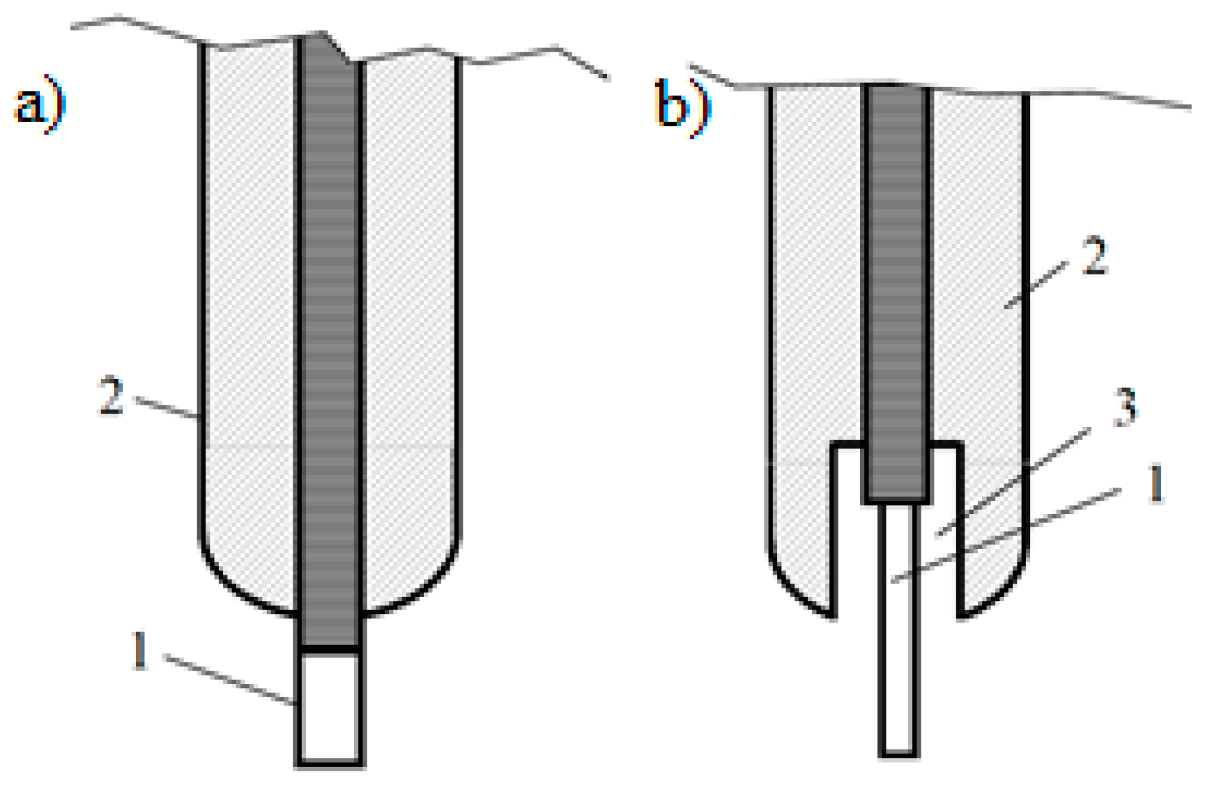
  • Sample № 1—the outer part of the front end of the positive electrode is completely insulated with fluoroplastic;
  • Sample № 2—the presence of a space between the insulation and the electrode, as well as a 1.5 times reduction of the diameter of the front end of the electrode compared with its main diameter.
For both models, the front end of the metal rod extended 10 mm beyond the insulation. During the research, the relationship between the insulation (fluoroplastic) diameter and the electrode diameter was determined (Table 2 and Table 3). The electrode tests were conducted under the following parameters of the electric impulse installation: capacitor capacity—C = 2 μF, electric impulse discharge voltage (U)—30 kV and 40 kV, and number of pulsed discharges—N = 2000–8000. The distance between the positive and negative electrodes was 25 mm.
During the experimental studies, electrode insulation diameters with ratios of D = 1.5 × d, D = 2 × d, and D = 2.5 × d proved to be unstable under the impact of pulsed discharges. Therefore, the results are presented starting from the ratio D = 3 × d. The distance between the electrode and its insulation (S) was determined based on the diameter of the positive electrode. The work on the electrode tests were repeated several times (5 times) and investigations continued until the electrode insulation defect was observed. The discharge voltage was monitored using a kilovoltmeter with an error of no more than ±4%. The values of the electrical impulse discharge parameters and the geometric parameters of the device (electrode and insulation diameter, distance between insulation and electrode) represent averaged values based on multiple measurements results.
The insulation resistance to electric pulse discharges was assessed after every 2000 discharges. Based on the data in Table 2, it was found that when selecting an insulation diameter with D = 3 × d, the fluoroplastic material collapsed after 4000 discharges at U = 30 kV pulse discharge voltage. With a ratio of D = 4 × d, damage occurs after 6000 discharges. At D = 5 × d, the fluoroplast undergoes deformation, while at U = 30 kV, the insulator is damaged after 8000 discharges. At a ratio of D = 6 × d, the insulation withstands electrical impulse action (results at U = 30 kV). However, when the voltage is increased to U = 40 kV, damage occurs after only 6000 more discharges. From the results obtained for sample № 1, we can see that even with an increase in the insulation diameter up to 6 times the diameter of the metal electrode, fluoroplast does not withstand the effects of the pulsed discharge. It was observed that the insulation did not deform at D = 7 × d. Since a further increase in the electrode diameter leads to a decrease in the volume of the working chamber, experiments with this type of sample were discontinued.
For sample № 2, the distance between the metal electrode and its insulation was S = 2.5 mm (Table 3). The following optimal test results were obtained for this model type, depending on the electric impulse discharge:
  • by increasing the insulation diameter 4 times relative to the metal electrode diameter (D = 4 × d), an effective working electrode variant, resistant to electric impulse discharge impact, was achieved;
  • based on the experimental results, a possible saving in insulation material was observed compared to sample № 1.
The following studies focused on determining the optimal distance ratio between the electrode and its insulation (see Figure 7). During the tests, the gap between the insulator and the electrode varied from 1 mm to 8 mm. The experiment was conducted under the following conditions: number of pulsed discharges (N)—2500–10,000, capacitor capacity—C = 2 μF, and discharge voltage (U) 30–50 kV (Table 4).
The results of the research showed that the ratio (S) between the insulation of the positive electrode and its metal rod, one of the main devices for forming a pulsed electric discharge in a liquid medium, should be from 3 mm to 8 mm. A further increase in the space between the electrode and its insulation led to a thinning of the insulation thickness of the electrode system.
The resistance of an electrode of this shape to electrical impulse discharges is explained as follows:
  • The liquid (technical water) in the space between the electrode and the insulation serves as additional insulation and prevents damage to the fluoroplastic.
  • The protruding part of the electrode from the insulation diverts streamers from the fluoroplastic. This is explained by the fact that streamers usually grow intensively from the end of the electrode.
  • The active surface of the end of the thin electrode protruding far from the insulation, due to its small diameter, does not exceed the active surface of the usually used thick electrode, which slightly protrudes from the insulation [28].
  • Thus, the electrode design promotes efficient electric field distribution and reduces the risk of electrical breakdowns in the fluoroplastic insulation. This ensures high electrode reliability under pulsed discharge conditions, protecting the insulating materials from degradation and extending the device’s lifespan [29]. Additionally, this design allows for optimal control of the electrical load and reduces the likelihood of local overheating on the material’s surface, which is a critical factor for system reliability. The use of an electrode with high mechanical strength and thermal resistance, combined with its optimized shape, minimizes energy losses and ensures stable operation under dynamic electric field conditions. Therefore, this electrode design not only extends its service life but also enhances the overall efficiency of the system, ensuring reliable performance under pulsed electrical discharges.

3.2. Grinding of Coal by the Electric Impulse Method

This paper proposed a method for grinding coal based on the use of the energy of pulsed shock waves generated by a spark electric discharge in a liquid (technical water), which makes it possible to solve a number of problems associated with the disintegration of natural raw materials. Experimental researches on coal grinding were carried out under the following conditions (Figure 8):
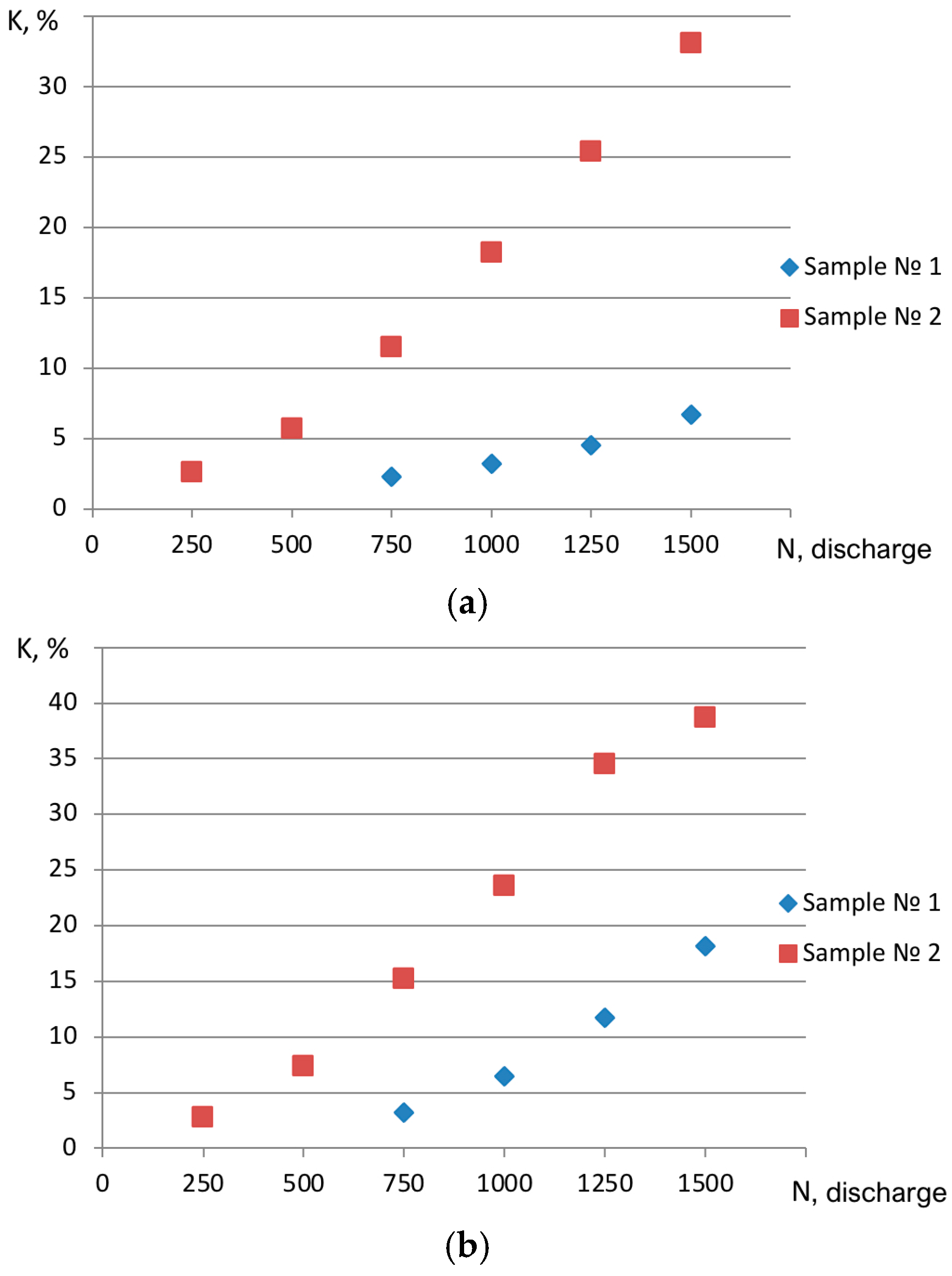
  • capacitor capacitance—from 0.25 μF to 1 μF (to increase the electric capacitance of the capacitor, 4 capacitors with the same nominal voltage and capacitance (100 kV, C = 0.25 μF) were connected in parallel);
  • pulse discharge voltage—U = 32 kV;
  • number of pulse discharges from 250 to 1500;
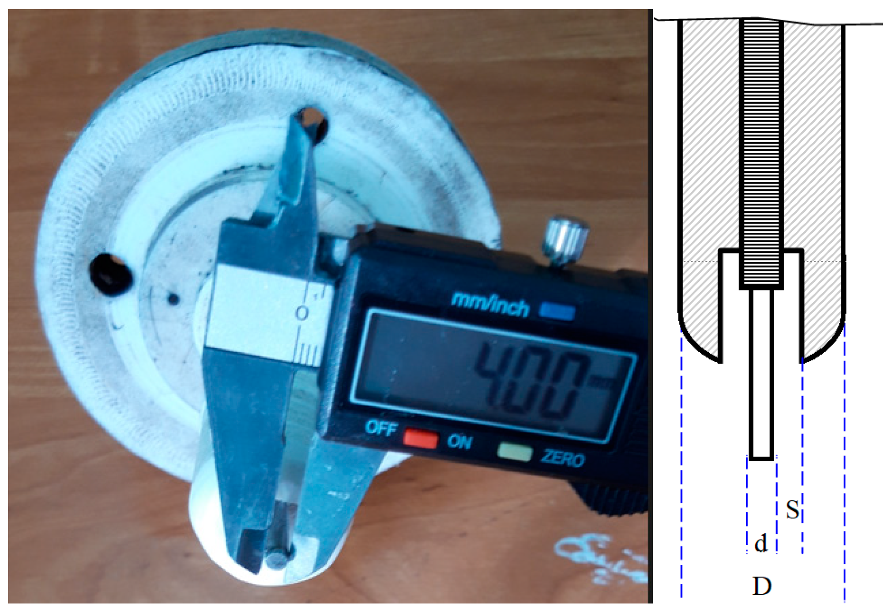
  • electrode sample № 1: electrode insulation diameter, depending on the diameter of the metal electrode—D = 7 × d;
  • electrode sample № 2: distance between the metal electrode and its insulation—S = 3 mm; electrode insulation diameter, depending on the diameter of the metal electrode—D = 4 × d.
The parameters of the feedstock for each experiment were constant: fraction diameter—9–15 mm, weight—100 g. The diameter of the resulting product was less than 200 μm. The weight of the raw material, before and after processing by the electric impulse method, was determined using electronic scales (maximum load—1200 g; resolution—0.001 g). The diameter of the fraction of the feedstock was determined using an electronic (digital) caliper (indicator resolution step of 0.01 mm). Analysis of the granulometric composition of the coal powder obtained by the electric impulse method was determined by the sieve method according to GOST 12536-2014 “Methods of laboratory determination of granulometric (grain) and microaggregate composition”. The crushed coal powder was sifted through a sieve with a hole diameter of 200 μm (the sieve was calibrated in accordance with GOST 51568-99).
The yield of the finished product was determined as follows: K = (m1/m2)·100%; m1 is the average mass of sifted coal powder from a sieve with a grid diameter of 200 µm after grinding using the electric impulse method, while m2 is the mass of the original raw material.
From Figure 8, it can be seen that increasing the capacitor capacity—(a) C = 0.25 μF, (b) C = 0.5 μF, (c) C = 0.75 μF, and (d) C = 1 μF)—and the number of pulse discharges (N = 250–1500) increases the yield of the final product. This was achieved when the positive electrode system in the coal grinding chamber had a special space between the metal rod and the insulation (compared to the sample of electrode № 1, that is, with the results of obtaining carbon powder, when the outer part of the front end of the positive electrode is completely insulated with fluoroplastic).
The increased yield of the finished product is explained as follows: Due to the special space (S = 3 mm) between the insulator and the positive electrode, the diameter of the insulator of the electrode shown in sample № 2 is at the ratio D = 4 × d. When the outer part of the front end of the positive electrode was fully insulated with fluoroplastic, the insulation diameter reached D = 7 × d. It can be seen from this that the diameter of the electrode of sample № 2 is smaller than that of sample № 1. Therefore, the electrode in sample № 2 occupies less space within the grinding device. Due to this, the volume of the space exposed to pulsed electric discharges (a mixture of coal and water) expands.

4. Conclusions

Based on the analysis of the main results of scientific research, an electrode resistant to the effects of pulsed discharges was developed. Coal was crushed depending on the electrical and geometric parameters of the installation. Granulometric analyses of raw materials were carried out and the dependence of the yield of the finished product on the parameters of pulsed discharges was studied. As a result of the studies carried out using the electric impulse method, coal powder with a diameter of less than 200 μm was obtained. The results of the experiment make it possible to create an optimal version of the working chamber for crushing materials using the electric impulse method. In the future, we plan to obtain a product with a size of less than 100 μm and increase its quantity using the proposed method. For this purpose, it is planned to conduct special studies depending on the electrical parameters of the electric impulse installation and pulse discharges generated in the working channel for grinding the material.

Author Contributions

Conceptualization, A.K.K. and D.Z.K.; Methodology, A.K.K., M.M.B., A.S.K., S.S.K. and L.V.C.; Validation, M.M.B.; Formal analysis, D.Z.K., M.M.B., A.S.K., S.S.K. and L.V.C.; Investigation, A.K.K., D.Z.K., M.M.B., A.S.K., S.S.K. and L.V.C.; Resources, A.K.K.; Writing—original draft, A.K.K., D.Z.K. and M.M.B.; Writing—review & editing, A.K.K., D.Z.K. and M.M.B.; Supervision, D.Z.K.; Project administration, A.K.K. All authors have read and agreed to the published version of the manuscript.

Funding

This research is funded by the Science Committee of the Ministry of Science and Higher Education of the Republic of Kazakhstan (Grant AP23488837).

Institutional Review Board Statement

Not applicable.

Informed Consent Statement

Not applicable.

Data Availability Statement

The data presented in this study are available on request from the corresponding authors.

Conflicts of Interest

The authors declare no conflict of interest.

References

  1. World Energy Council. World Energy Resources: Coal 2013. 2013. Available online: https://www.worldenergy.org/assets/images/imported/2013/10/WER_2013_1_Coal.pdf (accessed on 1 October 2013).
  2. IPCC. Climate Change 2007: Synthesis Report. 2007. Available online: https://www.enviro.wiki/images/b/be/2007-IPCC-Climate_change_synthesis_report.pdf (accessed on 1 October 2013).
  3. IEA. IEA Coal Research: Clean Coal Centre. Advances in Multi-Pollutant Control. 2013. Available online: https://usea.org/sites/default/files/112013_Advances%20in%20multi-pollutant%20control_ccc227.pdf (accessed on 1 October 2013).
  4. Pudasainee, D.; Kim, J.H.; Yoon, Y.S.; Seo, Y.C. Oxidation, reemission and mass distribution of mercury in bituminous coal fired power plants with SCR, CS-ESP and wet FGD. Fuel 2012, 93, 312–318. [Google Scholar] [CrossRef]
  5. World Coal Institute. Coal: Liquid Fuels. 2009. Available online: https://web.archive.org/web/20151122232436/http://www.worldcoal.org/sites/default/files/coal_liquid_fuels_report(03_06_2009).pdf (accessed on 1 October 2013).
  6. Snetkova, I.M. Production Technology and Fuel and Energy Characteristics of Alternative Liquid Coal Fuel; Gornaya Kniga: Moscow, Russia, 2008; pp. 182–189. [Google Scholar]
  7. Serant, F.A.; Tsepenok, A.I.; Ovchinnikov, Y.V.; Lutsenko, S.V.; Karpov, E.G. Preparation of water-coal fuel and its combustion technologies. Mod. Sci. 2011, 1, 95–101. Available online: https://modern.science.triacon.org/ru/issues/2011/files/papers/1/95-101.pdf (accessed on 1 October 2013).
  8. Maloletnev, A.S.; Naumov, K.I. Coal-Derived Liquid Fuel; Gornaya Kniga: Moscow Russia, 2014; pp. 227–237. [Google Scholar]
  9. Zenkov, A.; Sokolova, E.Y. Coal-Water Slurry. Language and World Culture: The View of Young Researchers: Proceedings of the XV All-Russian Scientific and Practical Conference; TPU: Nakano, Tokyo; Toms, Russia, 2016; Volueme 3, pp. 152–157. Available online: https://earchive.tpu.ru/bitstream/11683/32428/1/conference_tpu-2016-C89_V3_p152-157.pdf (accessed on 1 October 2013).
  10. Ibragimov, N.I.; Mukolyants, A.A.; Ergasheva, D.K.; Babaev, M.S. Research and development of technology for obtaining coal-water suspension based on coal from the Angren coal mine. Young Sci. Ecol. 2017, 8, 103–109. Available online: https://moluch.ru/archive/142/pdf/883/ (accessed on 1 October 2013).
  11. Bulkairova, G.; Nussupbekov, B.; Bolatbekova, M.; Khassenov, A.; Nussupbekov, U.; Karabekova, D. A research of the effect of an underwater electric explosion on the selectivity of destruction of quartz raw materials. East.-Eur. J. Enterp. Technol. 2023, 3, 30–37. [Google Scholar] [CrossRef]
  12. Dal Martello, E.; Bernardis, S.; Larsen, R.B.; Tranell, G.; Di Sabatino, M.; Arnberg, L. Electrical fragmentation as a novel route for the refinement of quartz raw materials for trace mineral impurities. Powder Technol. 2012, 224, 209–216. [Google Scholar] [CrossRef]
  13. Andres, U. Development and prospects of mineral liberation by electrical pulses. Int. J. Miner. Process. 2010, 97, 31–38. [Google Scholar] [CrossRef]
  14. Sperner, B.; Jonckheere, R.; Pfänder, J.A. Testing the influence of high-voltage mineral liberation on grain size, shape and yield, and on fission track and 40Ar/39Ar dating. Chem. Geol. 2014, 371, 83–95. [Google Scholar] [CrossRef]
  15. Khassenov, A.; Karabekova, D.; Bolatbekova, M.; Nussupbekov, B.; Kudussov, A.; Chirkova, L.; Kissabekova, P. Identification of the effect of electric impulse discharges on the recycling of household glass. East.-Eur. J. Enterp. Technol. 2024, 2, 6–13. [Google Scholar] [CrossRef]
  16. Duan, C.L.; Diao, Z.J.; Zhao, Y.M.; Huang, W. Liberation of valuable materials in waste printed circuit boards by high-voltage electrical pulses. Miner. Eng. 2015, 70, 170–177. [Google Scholar] [CrossRef]
  17. Louis, J.C.; Thomas, O.; Vladimir, N.R. Electric-pulse disaggregation (EPD), Hydroseparation (HS) and their use in combination for mineral processing and advanced characterization of ores. In Proceedings of the 40th Annual Canadian Mineral Processors Conference, Ottawa, ON, Canada, 22–24 January 2008; pp. 211–235. Available online: https://www.researchgate.net/publication/281466029 (accessed on 1 October 2013).
  18. Kurytnik, I.P.; Khassenov, A.K.; Nussupbekov, U.B.; Karabekova, D.Z.; Nussupbekov, B.R.; Bolatbekova, M. Development of a grinding device for producing coal powder-raw materials of coal-water fuel. Arch. Mech. Eng. 2022, 69, 259–268. [Google Scholar] [CrossRef]
  19. Robak, J.; Ignasiak, K.; Rejdak, M. Coal micronization studies in vibrating mill in terms of Coal-Water Slurry (CWS) Fuel preparation. J. Ecol. Eng. 2017, 18, 111–118. [Google Scholar] [CrossRef]
  20. Xiankai, B.; Jiaxing, C.; Wenxiang, Z.; Junyu, G.; Yuan, L.; Jinchang, Z. Study on the damage model of coal rock caused by hydraulic pressure and electrical impulse in borehole. Geofluids 2021, 19, 6627242. [Google Scholar] [CrossRef]
  21. Zhang, X.; Lin, B.; Li, Y.; Zhu, C. Experimental study on the effect of coal thickness and breakdown voltage on energy conversion during electrical disintegration. Fuel 2020, 259, 116135. [Google Scholar] [CrossRef]
  22. Zhang, X.; Lin, B.; Li, Y. Experimental study on the effects of electrode materials on coal breaking by plasma. Fuel 2020, 270, 117085. [Google Scholar] [CrossRef]
  23. Nussupbekov, B.; Khassenov, A.; Nussupbekov, U.; Akhmadiyev, B.; Karabekova, D.; Kutum, B.; Tanasheva, N. Development of technology for obtaining coal-water fuel. East.-Eur. J. Enterp. Technol. 2022, 3, 39–46. [Google Scholar] [CrossRef]
  24. Krutilin, A.K.; Bestuzhev, Y.K.; Bestuzhev, A.K.; Kalenkovich, D.K. Grinding bodies: Problems and prospects. Repub. Sci. Tech. J. Cast. Metall. 2009, 4, 26–33. Available online: https://cyberleninka.ru/article/n/melyuschie-tela-problemy-perspektivy?utm_source=chatgpt.com (accessed on 1 October 2013).
  25. Litvinsky, G.G. Impact jaw crusher with hydraulic drive. Mech. Eng. Mach. Sci. 2023, 31, 75–93. Available online: https://cyberleninka.ru/article/n/udarnaya-schekovaya-drobilka-s-gidroprivodom-problemy-i-resheniya?utm_source=chatgpt.com (accessed on 1 October 2013).
  26. Plashchinsky, V.A.; Beloglazov, I.I.; Akhmerov, E.V. Analysis of the wear model of working elements of a ball mill in the process of ore grinding. MIAB Min. Inform. Anal. Bull. 2024, 7, 91–110. [Google Scholar] [CrossRef]
  27. Yutkin, L.A. Electrohydraulic Effect and Its Application in Industry; Mechanical Engineering: Leningrad, Russia, 1986; p. 253. [Google Scholar]
  28. Starkov, N.V. Compact electrode systems of pulsed electrohydraulic (EG) installations. Electron. Process. Mater. 2014, 50, 115–120. Available online: https://cyberleninka.ru/article/n/kompaktnye-elektrodnye-sistemy-impulsnyh-elektrogidravlicheskih-eg-ustanovok/viewer (accessed on 1 October 2013).
  29. Kurets, V.I.; Soloviev, M.A.; Zhuchkov, A.I.; Barskaya, A.V. Electric Discharge Technologies for Processing and Destruction of Materials; Publishing House of Tomsk Polytechnic University: Tomsk, Russia, 2012. [Google Scholar]
Figure 1. Control block.
Applsci 15 03607 g001
Figure 2. Generator with forming gap.
Applsci 15 03607 g002
Figure 3. Capacitor and installation protection system.
Applsci 15 03607 g003
Figure 4. Change in the voltage of a pulsed discharge depending on the distance between hemispherical metal electrodes in the forming gap.
Applsci 15 03607 g004
Figure 5. Working chamber for grinding coal: (a) working chamber; (b) top view of the working chamber lid; (c) the inner surface of the reservoir of the working chamber; (d) a positive electrode insulated with fluoroplastic.
Applsci 15 03607 g005
Figure 6. The positive electrode: (a) the outer part of the front end of the positive electrode is completely insulated with fluoroplast; (b) if there is a space between the insulation and the electrode; 1—metal rod; 2—fluoroplast; 3—the space between the metal electrode and its insulation.
Applsci 15 03607 g006
Figure 7. Front end of the working electrode: S is the distance between the electrode and its insulation, d is the electrode diameter (D = 4 mm), and D is the insulation diameter (mm).
Applsci 15 03607 g007
Figure 8. Dependence of the yield of the finished product on the capacity of the capacitor and the number of pulse discharges: sample № 1—the outer part of the front end of the positive electrode is completely insulated with fluoroplastic; sample № 2—in the presence of space between the insulation and the electrode (S = 3 mm); (a) C = 0.25 µF; (b) C = 0.5 µF; (c) C = 0.75 µF; (d) C = 1 µF.
Applsci 15 03607 g008aApplsci 15 03607 g008b
Table 1. Technical characteristics of the installation.
Working FluidTechnical Water
Power supply network parameters:
Voltage, V220
Frequency, Hz50
Power consumption, kW2.5
Table 2. Results of the research of the dependence of the insulation diameter (D) on the diameter of the electrode (d) for sample № 1.
N, Discharge2000400060008000
D = 3 × d, (D = 6 mm)
U = 30 kV+
D = 4 × d, (D = 6 mm)
U = 30 kV++
D = 5 × d, (D = 6 mm)
U = 30 kV+++
D = 6 × d, (D = 6 mm)
U = 30 kV++++
U = 40 kV++
D = 7 × d, (D = 6 mm)
U = 30 kV++++
U = 40 kV++++
Note: “+”—the fluoroplast is not damaged, “−”—the fluoroplast is damaged.
Table 3. Results of the research of the dependence of the insulation diameter (D) on the electrode diameter (d) for sample № 2.
N, Discharge2000400060008000
D = 2 × d, (D = 4 mm)
U = 30 kV++++
U = 40 kV
D = 3 × d, (D = 4 mm)
U = 30 kV++++
U = 40 kV++
D = 4 × d, (D = 4 mm)
U = 30 kV++++
U = 40 kV++++
Note: “+”—fluoroplastic is not damaged, “−”—fluoroplastic is damaged.
Table 4. Results of research then determine the ratio of distances between the electrode and its insulation.
N, Discharge25005000750010,000
S = 1 mm
U = 30 kV++++
U = 40 kV++
U = 50 kV
S = 2 mm
U = 30 kV++++
U = 40 kV++++
U = 50 kV++
S = 3 mm
U = 30 kV++++
U = 40 kV++++
U = 50 kV++++
S = 8 mm
U = 30 kV++++
U = 40 kV++++
U = 50 kV++++
Note: “+”—fluoroplastic is not damaged, “−”—fluoroplastic is damaged.
Disclaimer/Publisher’s Note: The statements, opinions and data contained in all publications are solely those of the individual author(s) and contributor(s) and not of MDPI and/or the editor(s). MDPI and/or the editor(s) disclaim responsibility for any injury to people or property resulting from any ideas, methods, instructions or products referred to in the content.

