1. Introduction
Railroads, as an important national transportation infrastructure, play an irreplaceable role both in the travel of the population and in the transportation of goods. With the increase in the speed of high-speed railcars and the frequent operation of trains, the detection of rail abrasion has been increasingly emphasized. Rail abrasion, as a key track geometric parameter, plays a vital role in later line maintenance and overhaul formulation [
1]. Wear and tear of rails can lead to changes in the contact relationship between wheels and rails, reducing the service life of rails as well as vehicles, increasing operating costs, and leading to crises in life safety [
2]. In order to ensure the safety and reliability of railroads, the accurate detection of rail wear is particularly important.
At present, rail wear detection is mainly divided into two kinds, namely contact and non-contact. Contact detection requires railroad staff to use detection tools to manually measure the rail head data, such as the common Mini Prof rail wear detector [
3]. But issues in the use of this method include the low efficiency of detection, low reliability, and the fact that it has not been adapted to the current requirements for rail wear detection [
4]. Non-contact detection is divided into passive detection and active detection according to the different imaging methods. In this case, passive detection is the establishment of a binocular vision system to make measurements, and active detection is the use of structured light to make measurements [
5]. Both have the advantage of fast measurement speed and high measurement accuracy [
6]. In particular, 3D line structured light has been widely used in object detection due to its large measurement range, large amount of collected data, and ability to comprehensively obtain the 3D point cloud data of the object under test [
7].
The 3D point cloud of the rail obtained by 3D line structured light needs to be aligned with the complete 3D point cloud of the rail before calculating the wear of the rail. Point cloud alignment is the data processing process of adjusting two pieces of point clouds at different positions in the same space to the same position through coordinate transformation. Since the alignment effect cannot be optimized at one time, it is usually divided into two stages: coarse alignment and fine alignment [
8]. Coarse alignment allows the two pieces of point clouds at the initial spatial position to be roughly aligned by coordinate transformation, while fine alignment aims to achieve further alignment on the basis of the coarse alignment [
9] in order to achieve minimization of the alignment error.
Coarse alignment is divided into two methods, one based on feature points and the other based on global search [
10]. The coarse alignment based on feature points is mainly carried out by extracting the corresponding feature information in the two point clouds, of which the most common ones are the Scale-Invariant Feature Transform (SIFT) algorithm [
11], the Harris3D feature point algorithm [
12], and the internal shape signature (ISS) algorithm [
13]. As for the alignment algorithm based on global search, Chen Yi et al. [
14] proposed a Principal Component Analysis (PCA) algorithm based on contour distance improvement to realize efficient point cloud auto alignment. Zhang Han et al. [
15] proposed an improved Sample Consistent Initial Alignment (SAC-IA) algorithm using geometric constraints via the scan angle limiting method. Aiger et al. [
16] proposed a 4-points congruent sets (4PCS) algorithm using 4-points sets corresponding to point congruence properties, which reduces the time complexity of the algorithm. Mellado et al. [
17] improved the 4PCS by proposing the Super-4PCS algorithm, which further reduced the time complexity of the 4PCS algorithm, and Pascal et al. [
18] proposed the K-4PCS algorithm in order to better adapt to the characteristics of laser scanning. In the fine alignment stage, the most widely used are those based on the Normal Distribution Transformation (NDT) [
19] algorithm and those based on the Iterative Closest Point (ICP) [
20] algorithm. The ICP algorithm needs to be iterated, and when the quantity of point cloud data is large enough, the algorithm will take longer. In order to solve this time-consuming problem, researchers have conducted a significant amount of research. Chen J et al. [
21] proposed the HT-ICP algorithm, which reduces the computation time by eliminating the incorrectly corresponding point pairs. Segal et al. [
22] proposed the GICP algorithm, which improves the accuracy of the algorithm through the introduction of oriented quantities and curvature geometric features. Shen Chen et al. [
23] used the kd-tree accelerated ICP algorithm on robot disassembly targets to realize point cloud fine alignment.
Due to the large amount of data obtained from rail collection, the time complexity of point cloud alignment tends to be high, which makes the algorithm suffer in terms of both operation efficiency and alignment accuracy [
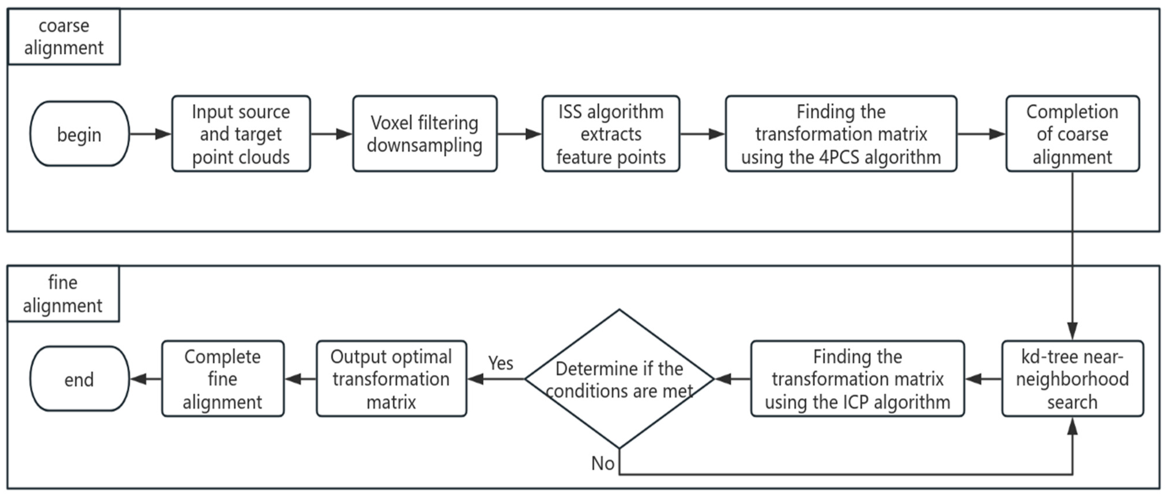
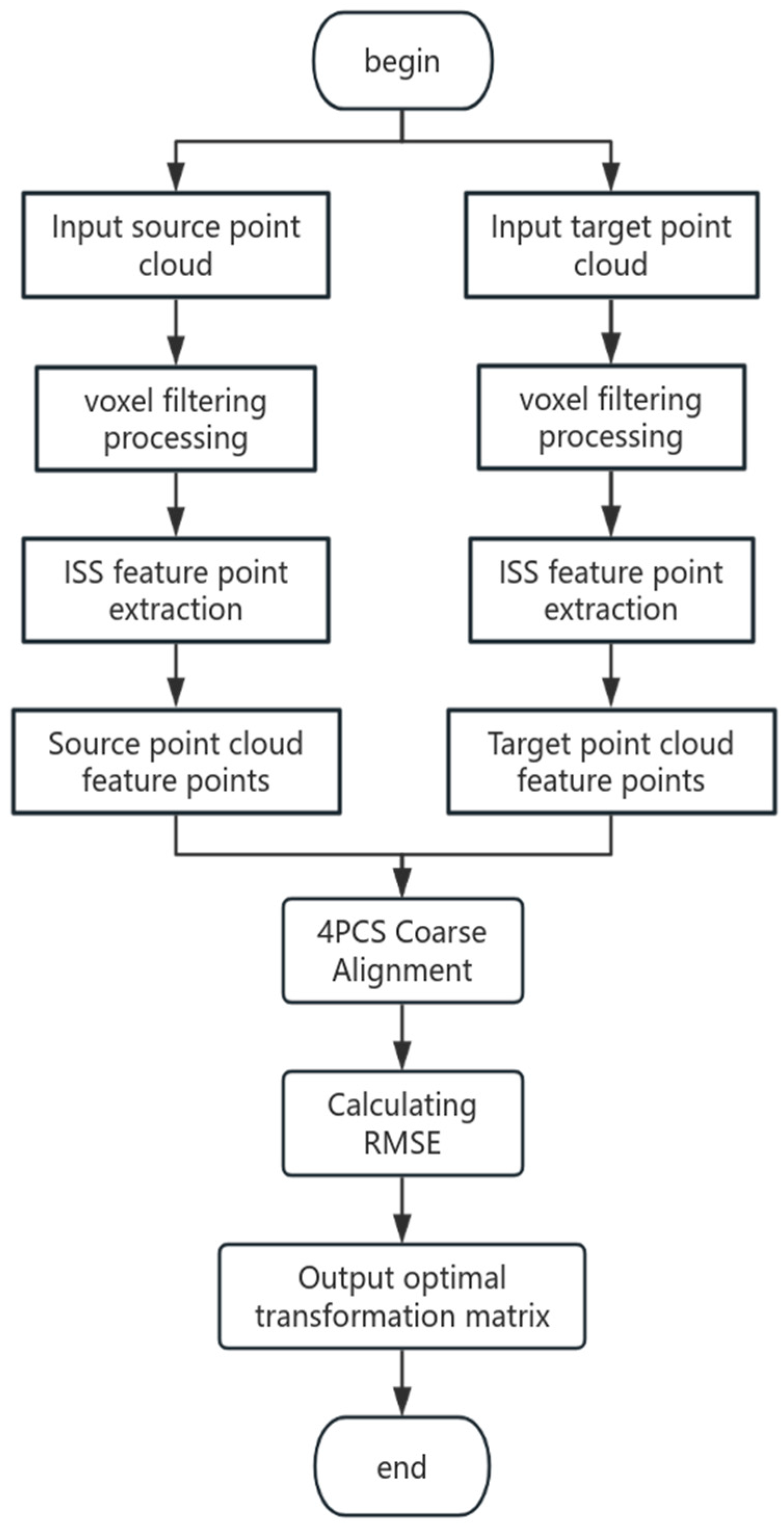
24]. To address the above problems, a point cloud alignment method combining ISS-4PCS and KD-ICP is proposed in this work. That is, ISS feature points are integrated on the basis of the 4PCS algorithm, a 4PCS coarse alignment algorithm based on ISS feature points is proposed, and the KD-ICP algorithm proposed by Shen Chen et al. is applied to rail abrasion detection for fine alignment. The method consists of two stages: ISS-4PCS coarse alignment and KD-ICP fine alignment; the specific realization steps are as follows. In the coarse alignment stage, the voxel filtering is used to downsample the source and target point clouds to be aligned, then the ISS feature point extraction algorithm is used to extract the source and target point cloud feature point sets, and finally the 4PCS algorithm is used to complete the coarse alignment. In the fine alignment stage, the kd-tree near-neighborhood search is used to accelerate the ICP algorithm to complete the fine alignment. This method uses the ISS algorithm to extract the feature points to replace the original data points, which can improve the alignment accuracy of 4PCS algorithm; the use of kd-tree to accelerate the ICP algorithm can improve the alignment efficiency of the ICP algorithm, and the flow of the method used is shown in
Figure 1. Experiments show that the combined algorithm proposed in this paper has better robustness in rail point cloud alignment.
3. Point Cloud Alignment Methods
3.1. ISS Feature Point Extraction
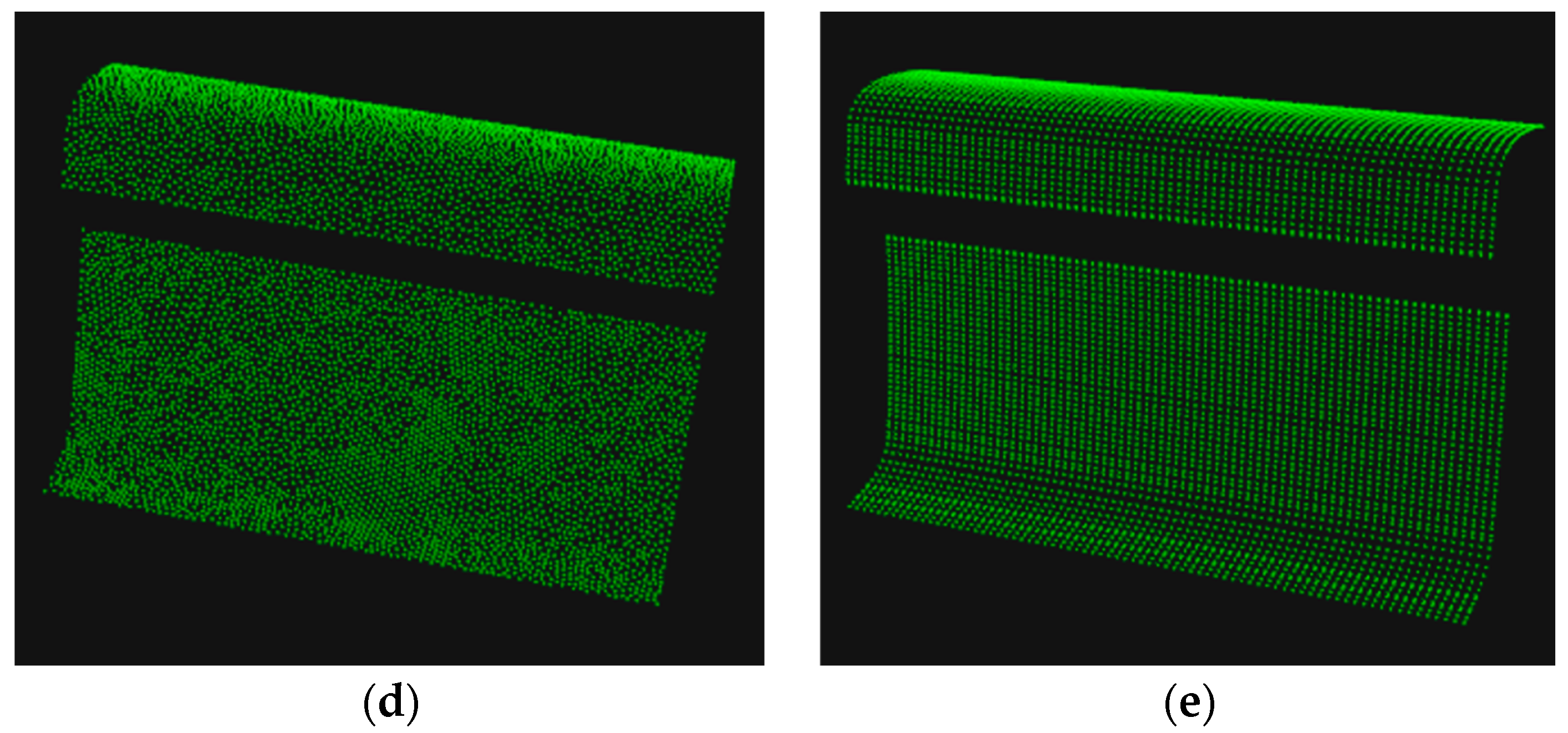
The point cloud data obtained by downsampling the point cloud still has a large amount of data, and direct point cloud calculation is not only complex but also time-consuming, which affects the speed of data processing. Therefore, representative feature points can be extracted from the source and target point clouds before point cloud alignment. This ensures that the spatial structure of the original data features remain unchanged on the premise of the extracted feature points for the later point cloud alignment work. This reduces the amount of data processed in the point cloud and improves the efficiency of point cloud alignment. Considering the geometric characteristics of point cloud data, ISS feature points are selected as the extraction method. If the point cloud set P contains n points, let pi = (xi,yi,zi), the specific process of extracting feature points is as follows:
Step 1: Establish a local coordinate system for each point
pi in the point cloud set and set a search radius
r for these points; determine all the points
pj in the point cloud set each centered on
pi and within the region of radius
r. Calculate the weights
wij of these points with the following expression:
Step 2: Calculate the covariance matrix of each point
pi with all the points in the neighborhood radius
r:
Step 3: Calculate the eigenvalue of covariance matrix
cov(
pi) for each point
pi in the point cloud set. Because the extraction of feature points has a correlation with the size of their eigenvalues, the eigenvalues are arranged in order from the largest to the smallest in order to select the feature points according to the size of the eigenvalues. Then, set the threshold
ε1,
ε2, take the smallest eigenvalue as the significant feature. The one that satisfies the condition of the following equation is the extracted ISS feature point, where the value of
ε1,
ε2 is generally less than 1.
3.2. 4PCS Point Cloud Coarse Alignment
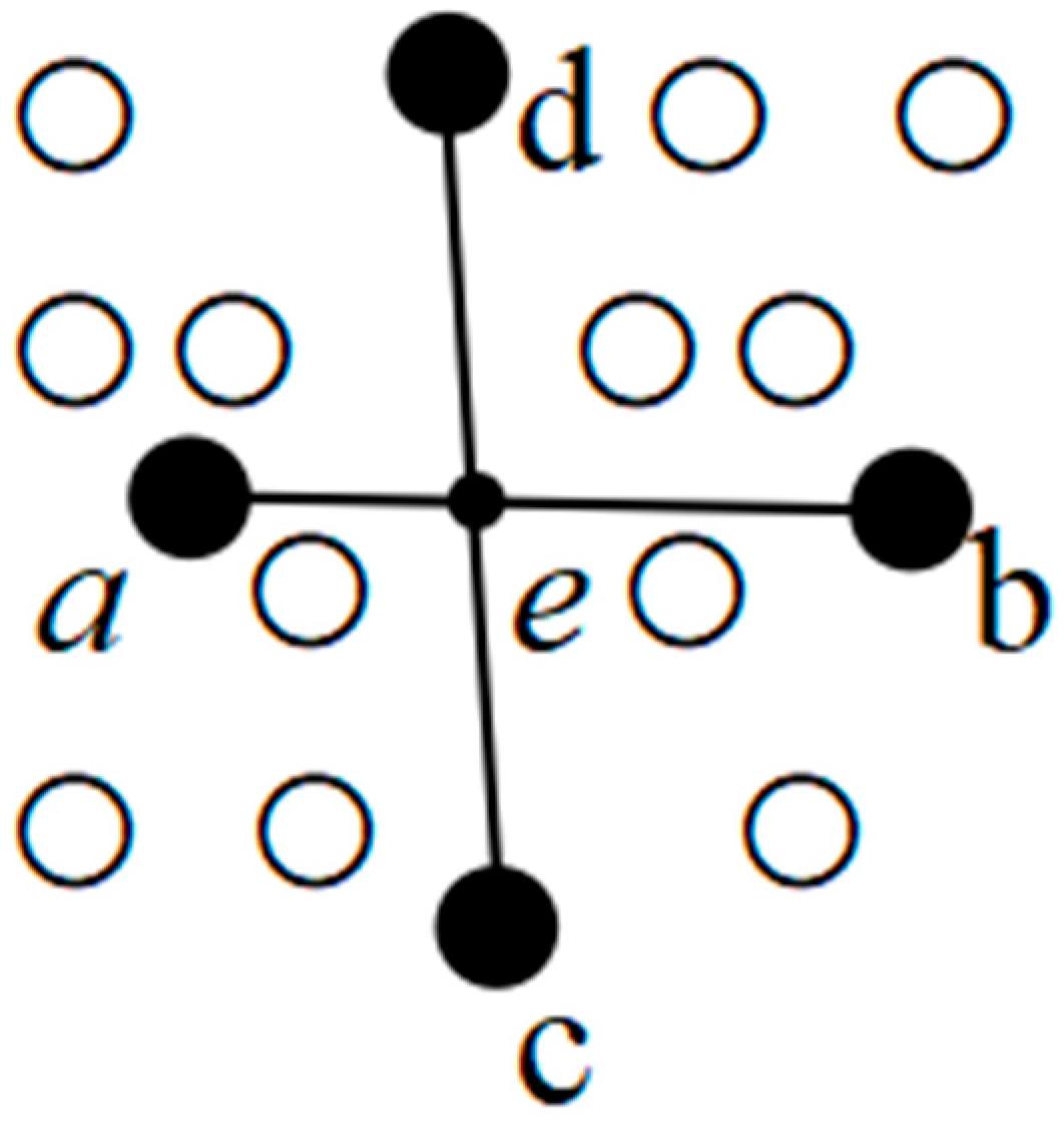
The 4PCS algorithm is a popular point cloud coarse alignment algorithm that performs a full-range search of a point cloud dataset under specified constraints. As shown in
Figure 5, the basic principle of the 4PCS algorithm is as follows: randomly select 4 points (a, b, c, d) that are coplanar but not collinear in the source point cloud set
P to form a point set
B, where the line from ab intersects the line from cd at point e. Then, select 4 pairs of coplanar but not collinear points that are congruent with point set
B from the target point cloud set
Q and compute the optimal transformation matrix
T.
The specific steps to implement the 4PCS algorithm are as follows:
Step 1: Four points that are coplanar and noncollinear are selected from the source point cloud set P to form a 4-point set B = {a, b, c, d}, and two affine invariant scale factors r
1 and r
2 are defined in this point set with the following expressions:
Step 2: Based on the calculated scale factors r1 and r2, all the point sets B’ = {a’, b’, c’, d’} that are consistent with the point set B within the permissible range are traversed from within the target point cloud set Q, and the time complexity of the algorithm is O(n2 + k) (a measure of the complexity of the execution time of the algorithm, n is the number of candidate points and k is the number of 4-point sets). Then, traverse all the point sets B’ to find the rigid body transformation matrix Ti of the point sets B and B’ using the least squares method.
Step 3: Through many iterations, the minimum distance between the source point cloud and the target point cloud after rigid-body transformation is calculated. The sum of the squares of the minimum distances is used as the optimal solution of the rigid-body transformation to realize the coarse alignment of the point cloud.
3.3. 4PCS Coarse Alignment Based on ISS Feature Points
When the 4PCS algorithm is applied to point cloud coarse alignment, due to the need to traverse all the 4-point sets from the target point cloud that have affine invariant consistency features with the source point cloud, which leads to a long time and inefficiency of the coarse alignment. To address the above problems, this paper introduces ISS feature points on the basis of 4PCS algorithm. Although the time complexity
O(
n2 +
k) of searching for point pairs in the target point cloud remains unchanged, the number of points searched by the algorithm is reduced due to the ISS feature points extracted from the source point cloud and the target point cloud, which in turn reduces the time of coarse alignment. The coarse alignment process based on the ISS feature points is shown in
Figure 6. After inputting the source and target point clouds at the same time, voxel filtering is used to downsample the source and target point clouds. Next, the ISS feature points are extracted to form the source and target point cloud feature points, and these feature points are used for 4PCS coarse alignment. Finally, the RMSE is computed and the optimal transformation matrix is output.
Step 1: Due to the large amount of data collected from the source and target point clouds, the two pieces of point clouds are downsampled first, and then the ISS algorithm is utilized to extract the feature points of the downsampled two pieces of point clouds.
Step 2: The feature points of the target point cloud are traversed by determining the coplanar disjoint 4-point set of the source point cloud feature points. The 4PCS coarse alignment is used to align the source point cloud feature points with the feature points of the target point cloud. Then, the least squares method is used to calculate the rigid-body transformation matrix of the two feature points.
Step 3: According to the derived rigid-body transformation matrix, the spatial positional transformation of the source point cloud feature points is performed. After several iterations, the sum of the nearest-point distances between the source and target point cloud feature points after the positional transformation is calculated. The rigid-body transformation matrix of the sum of the nearest-point distances will be used as the final positional transformation matrix outputted by the 4PCS algorithm between the source and target point cloud feature points.
Step 4: To analyze the error of the coarse alignment results, this paper chooses root mean square error (RMSE) as the evaluation index to measure the accuracy of the point cloud alignment. RMSE is used to quantify the size of the error of the alignment by calculating the square root of the ratio of the square sum of the distances of the matched pairs of
pi and
qi to the logarithmic value of
n, and the smaller the value, the better the result of the alignment. The expression is as follows:
3.4. ICP Fine Alignment Based on Kd-Tree
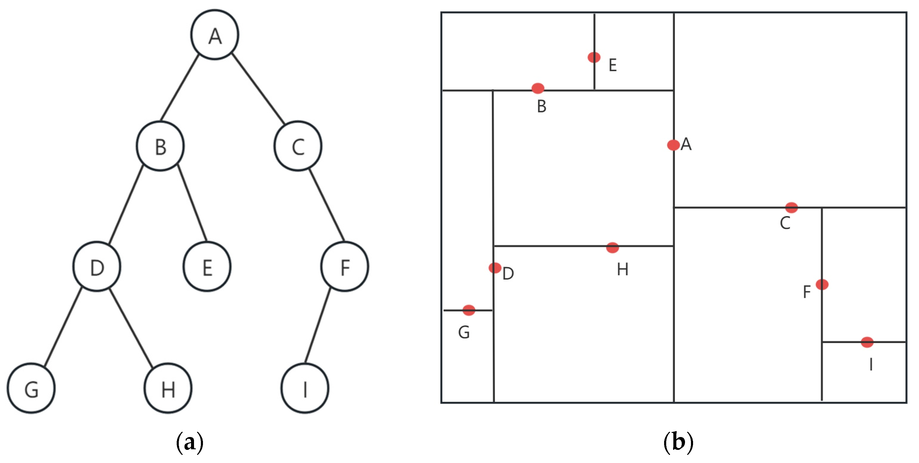
After the 4PCS coarse alignment stage, the contour between the source point cloud attitude transformation and the target point cloud can be basically overlapped. But there still exists a certain contour error, which requires fine alignment to improve the alignment accuracy. ICP is used as a classical point cloud alignment algorithm: through the matching of points to points and iteratively calculating the optimal solution of the transformation matrix of the source point cloud and the target point cloud, the alignment error is minimized. Because the ICP algorithm does not need any feature computation to achieve fast iteration to minimize the function error to get the required spatial transformation matrix, it is widely used in point cloud fine alignment. This paper adds the kd-tree on the basis of ICP to further optimize the computation time of the algorithm. kd-tree is a kind of tree data structure with a number of points in a k-dimensional space. It is widely used in range search and nearest neighbor search, as shown in
Figure 7, and its basic principle is as follows:
In kd-tree, the median value of each dimension is often used as the segmentation hyperplane. The root of the tree is the first dimension, and all child nodes are divided downward by this dimension. The basis for the division is as follows: if this node is smaller than the root node, it will be divided into the left branch of the next dimension; if it is larger than the root node, it will be divided into the right branch of the next dimension. Then, the second dimension after the division is the root node, which is divided according to the above division principle and then divided downward until the end of the leaf nodes.
The traditional point-to-point ICP algorithm uses the distance between the corresponding points of two point clouds as the objective function to calculate the transformation matrix. The point-to-face ICP algorithm adopted in this paper uses the distance from each point in the source point cloud to the plane where the normal vector of the corresponding point in the target point cloud is located as the alignment criterion, and then iterates to find the optimal transformation matrix to find the best solution. The main steps of the kd-tree based point-to-plane ICP algorithm are as follows:
Step 1: In order to solve the normal features of each point in the two point cloud sets, establish a kd-tree for near-neighborhood accelerated search on the source point cloud set P and the target point cloud set Q obtained after coarse alignment. Then, compute the weighting factor and feature descriptor based on the normal features, so as to find the corresponding point of each nearest neighbor of the source point cloud set P and the target point cloud set Q.
Step 2: The optimal transformation matrix
T is solved based on the found nearest neighbors with the objective function:
where
Rf is the rotation matrix;
Tf is the translation matrix;
pi and
qi are the corresponding points of the source point cloud set
P and the target point cloud set
Q; and
ni denotes the normal vector of the point
pi corresponding to
qi.
Step 3: Set the maximum number of iterations Nmax and the minimum threshold ε. Repeat the above steps; if the error of the two iterations is less than ε, i.e., Fn(Rf,Tf)-Fn-1(Rf,Tf) < ε, or the number of iterations is greater than Nmax, then stop iteration and find the final transformation matrix T. Otherwise, continue to iterate until it meets the iteration conditions.
5. Conclusions
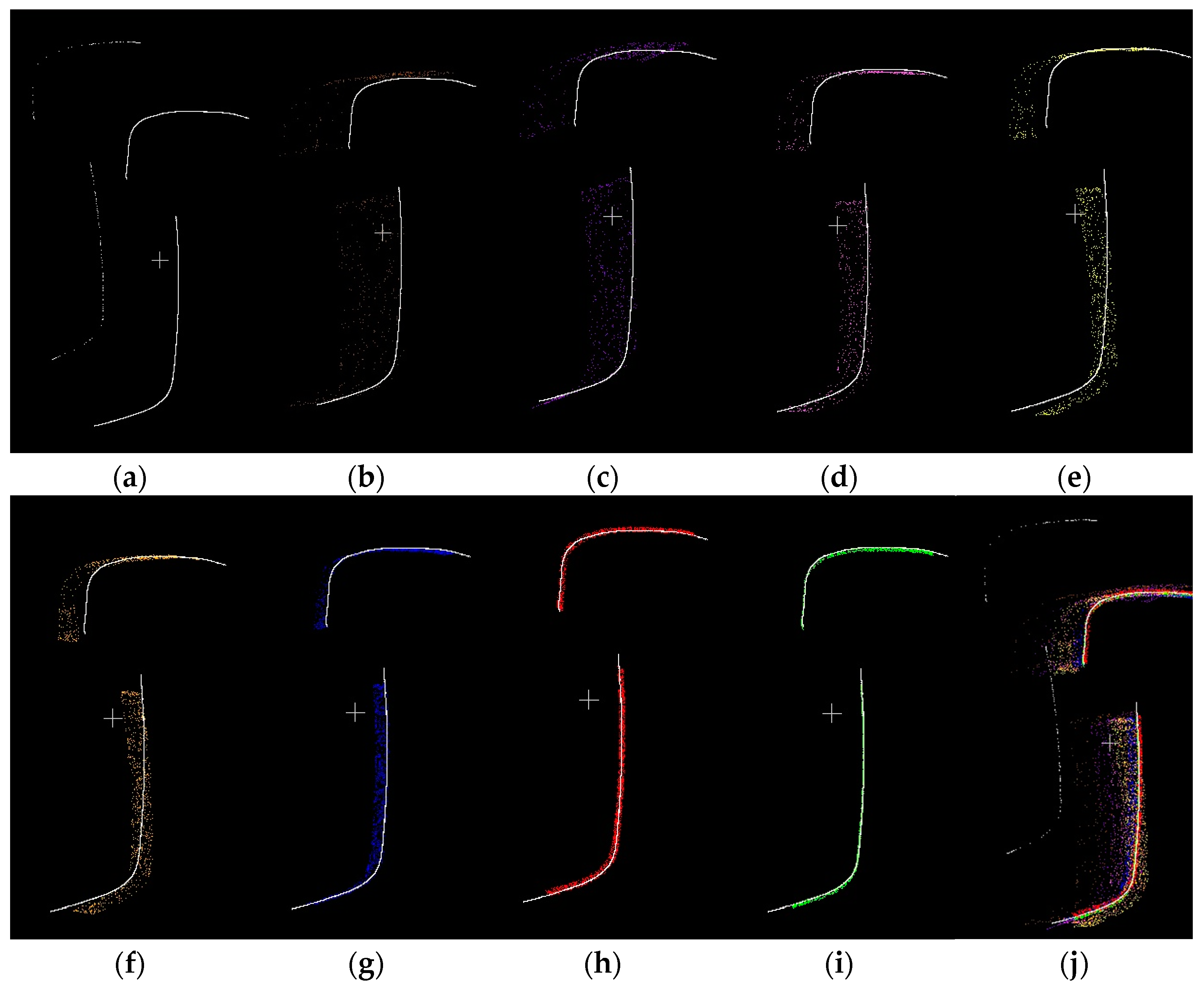
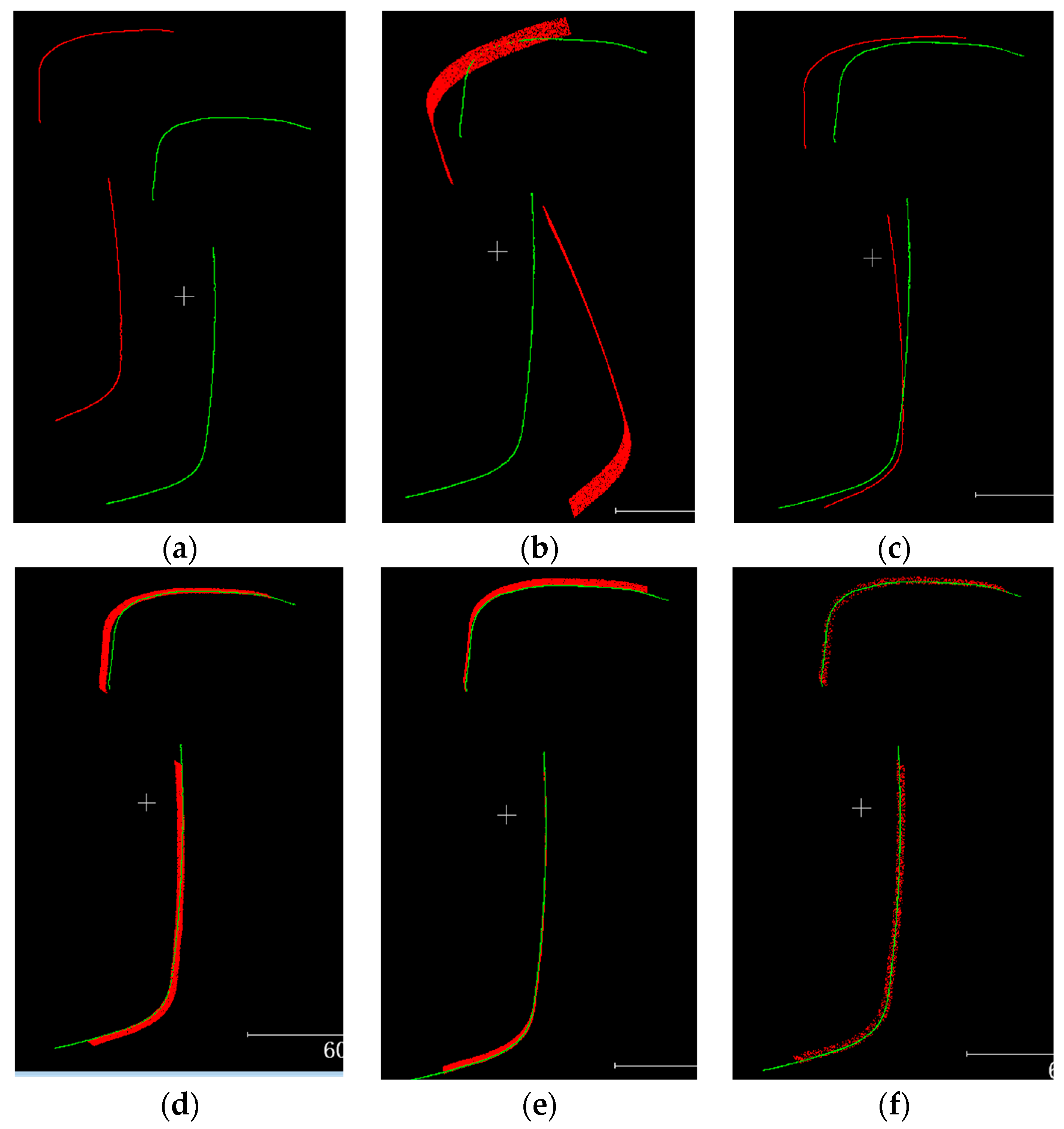
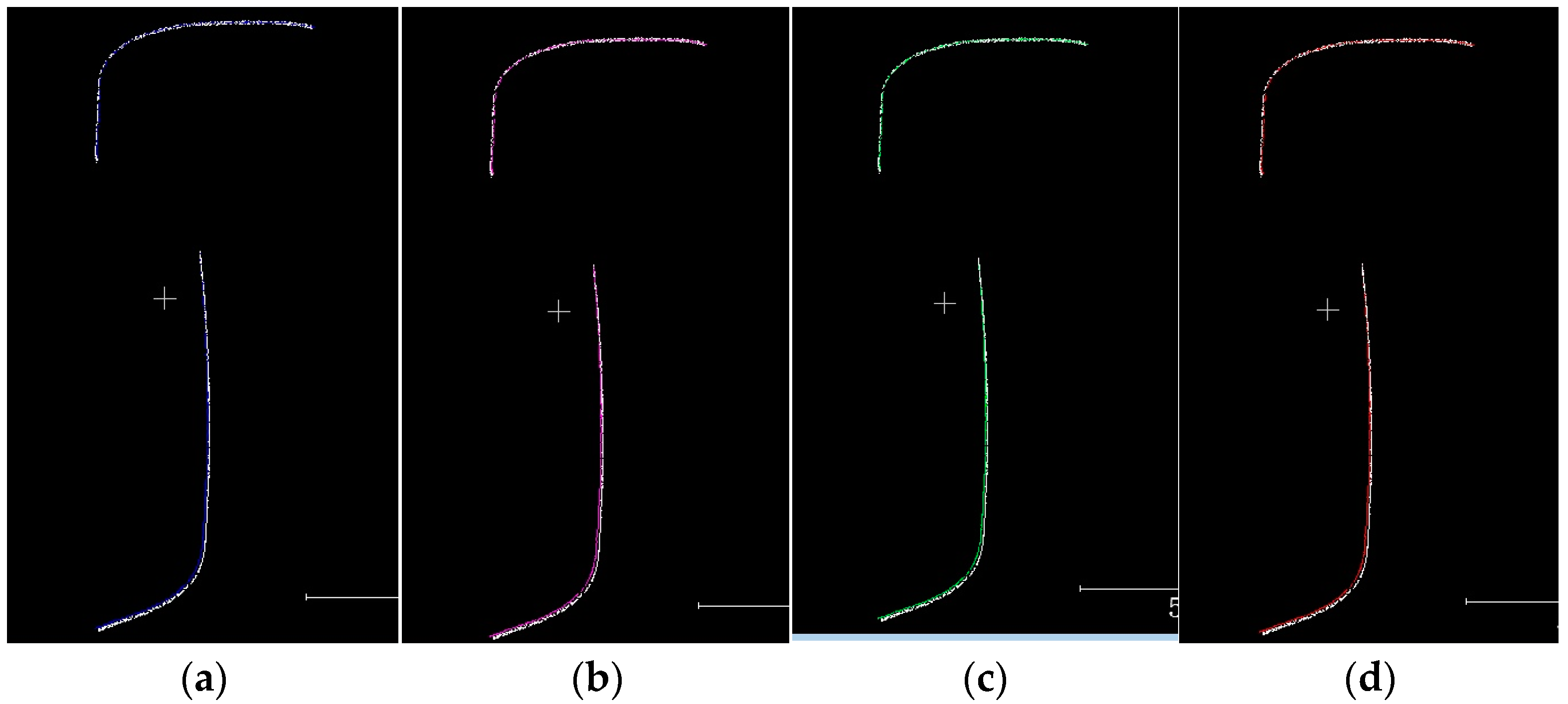
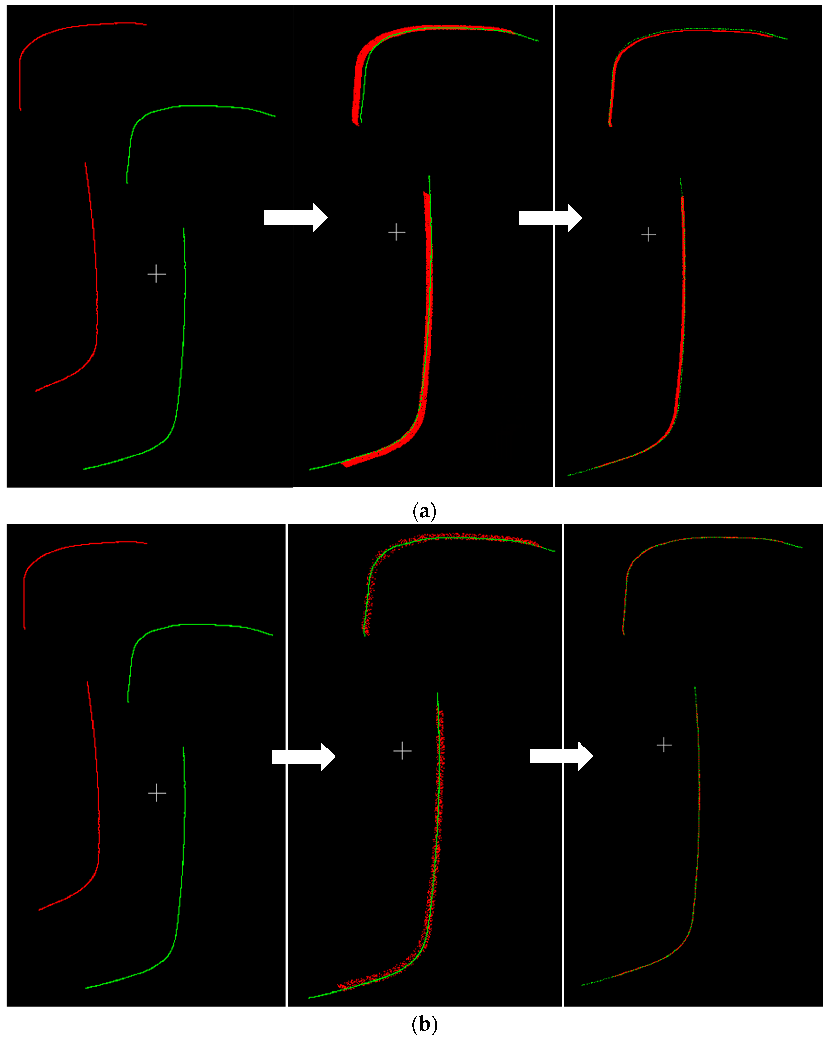
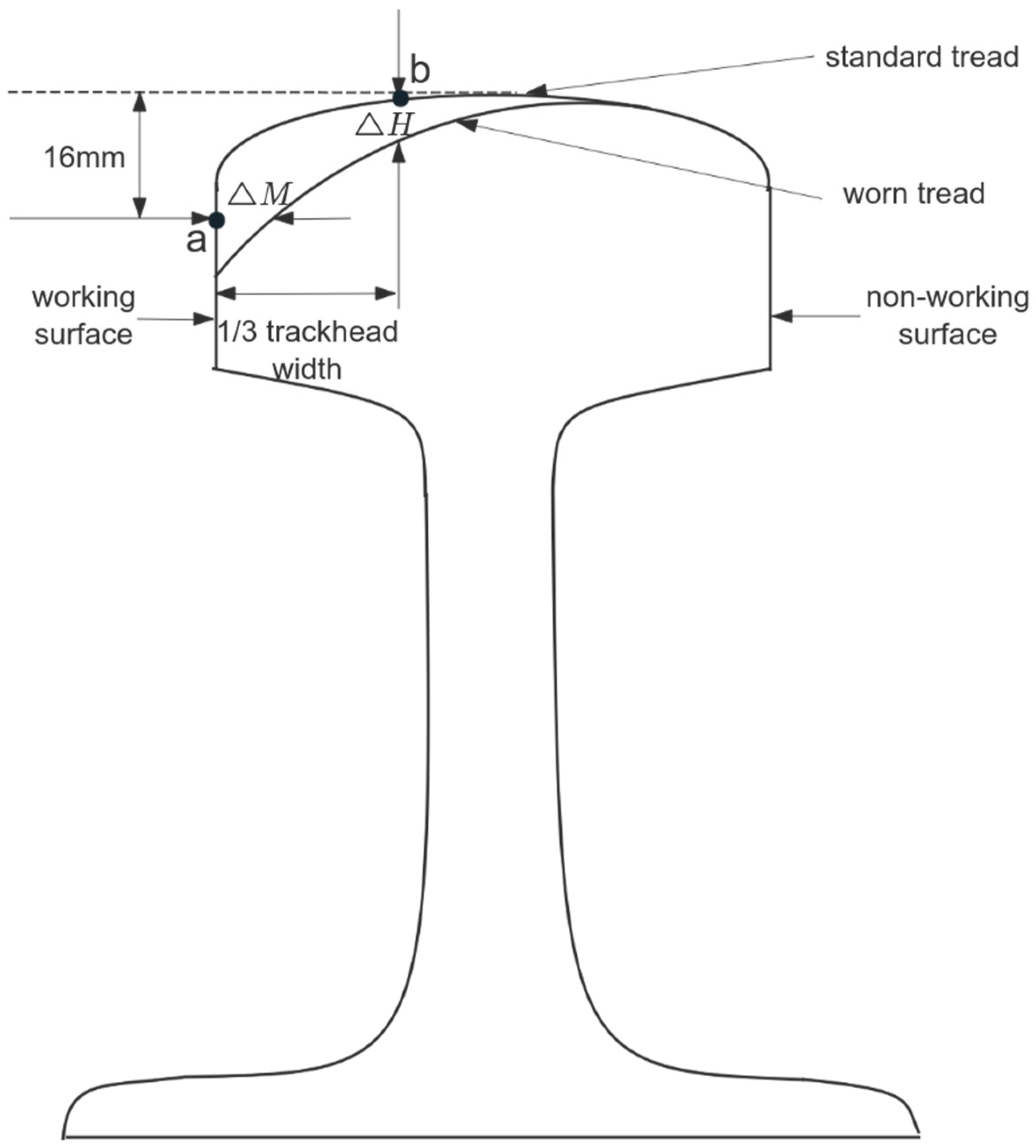
For the application of 3D line laser sensor for rail abrasion detection, a new point cloud alignment combination algorithm is proposed based on the use of voxel filtering downsampling, i.e., the combination algorithm of ISS-4PCS + KD-ICP. The experiment first downsampled the initial collected rail point cloud contour, and finally selected voxel filtering as the downsampling method for the rail point cloud contour by comprehensively considering the running time of the algorithm and the influence on the later point cloud alignment. Next, we quantitatively analyzed the extracted ISS feature points, discussed the influence of the number of extracted feature points on the coarse alignment, and determined the optimal case of the number of feature points. Considering that the proposed coarse alignment algorithm works best when the number of ISS feature points is 4496, the number of feature points of 4496 points was chosen as the number of feature points for the proposed 4PCS coarse alignment algorithm based on ISS feature points. Further, the proposed algorithm was compared and analyzed with other algorithms to verify the superiority of the proposed algorithm in terms of alignment time and accuracy. Finally, the rail vertical wear ΔH and horizontal wear ΔM were derived from the rail wear calculation experiment and then combined with the wear calculation formula to derive the total rail wear W and analyze it. The results show that the wear values measured by the ISS-4PCS + KD-ICP method used in this paper are within the permissible error range and meet the testing requirements. In the coarse alignment stage, the ISS-4PCS algorithm proposed in this paper not only improves the accuracy compared with other algorithms but also shortens the alignment time; in the fine alignment stage, although the KD-ICP algorithm used is similar to the other algorithms in terms of accuracy, it greatly shortens the alignment time and improves the efficiency of the algorithm. In general, the new method adopted in this paper shows great progress compared with the original method both in the alignment accuracy and the alignment time, which can greatly improve the detection efficiency of rail wear and provide a reference for non-contact rail wear detection methods. Although the ISS-4PCS + KD-ICP combination algorithm proposed in this paper presents better results on rail wear detection, it has not been applied on other models. Therefore, the next step is to extend the application of this combined algorithm on other models, especially on rail head geometry, in order to realize the wide range of the algorithm.


