Article

An Experimental Study of the Characteristics of Oxidation Displacement via Air Injection in a Deep, Medium–High-Pressure Reservoir

1
Research Institute of Petroleum Exploration and Development, PetroChina, Beijing 100083, China
2
State Key Laboratory of Enhanced Oil and Gas Recovery, PetroChina, Beijing 100083, China
*
Author to whom correspondence should be addressed.
Appl. Sci. 2025, 15(6), 3301; https://doi.org/10.3390/app15063301
Submission received: 17 January 2025 / Revised: 6 March 2025 / Accepted: 7 March 2025 / Published: 18 March 2025

Abstract

:
A high-temperature and high-pressure experimental device was upgraded to accommodate a maximum pressure of 40 MPa and a maximum temperature of 800 °C. Using this experimental device, one-dimensional oxidation displacement experiments were carried out via air injection in the Hudson original reservoir to change the pressure from low pressure (5 MPa) to high pressure (30 MPa) and via air injection after water injection under 30 MPa high-pressure conditions. A stable medium–high-temperature thermal oxidation front and displacement state could be formed in the experiments under different pressure measurements of 5 MPa, 15 MPa, and 30 MPa and in the air injection experiment after water injection under high pressure, at 30 MPa, which was similar to the oxidation front and displacement characteristics of heavy oil air injection in situ combustion. However, as the pressure increased, the air consumption and fuel consumption became smaller, and the temperature of the oxidation front became lower. And compared with the original reservoir, the air consumption and fuel consumption of air injection after water injection increased, and the temperature of the oxidation front became higher. This was completely different from the law of heavy oil in situ combustion. With the increase in pressure, the pore volume number (PV) of the injected air was smaller, the gas production/injection ratio was smaller, and the oil displacement efficiency was higher. Therefore, the stability of the 30 MPa high-pressure air injection displacement was better. The gas/oil ratio (GOR) produced by 30 MPa air injection after water injection in the experiment was stable, and air injection after water injection could reduce the water cut and greatly improve oil displacement efficiency. Therefore, air-injection-enhanced oil recovery technology was still feasible in the reservoir after water injection.

1. Introduction

As an efficient oil recovery technology, heavy oil air injection in in situ combustion technology has successfully been commercialized. The United States, Romania, India, and other countries have had very successful heavy oil in situ combustion industrialization projects [1,2,3]. China’s heavy oil in situ combustion technology is mainly used in heavy oil reservoirs after steam injection. This technology has successfully been applied in heavy oil reservoirs such as the Hongqian 1 block in the Xinjiang Oilfield and the Du 66 block in the Liaohe Oilfield [4]. Air injection in light oil reservoirs is generally used in deep, low-permeability reservoirs. The air injection pressure is higher, the matching process requirements are more stringent, and the mechanism of enhanced oil recovery (EOR) is more complicated. The Buffalo oilfield in the United States has carried out high-pressure air injection (HPAI) field tests in low-permeability, light oil reservoirs for many years. The coring data after air injection show that core oil displacement efficiency is more than 90%, which is much higher than that of conventional flue gas flooding, proving the great potential of light oil air injection development [2].
Domestic and foreign scholars have performed much research on types of air injection oxidation reactions, low-temperature oxidation characteristics, and flue gas displacement in light oil reservoirs [5,6,7,8,9,10,11,12,13,14,15,16]. International scholars have studied the oxygen consumption rate, displacement efficiency, oxidation heat release, and spontaneous combustion possibility of air injection in light oil. In most experiments, the oxygen consumption rate can essentially reach 100%, and 9% carbon dioxide and 1% carbon monoxide are produced. At the same time, air injection can significantly improve oil recovery [13]. The crude oil involved in this reaction is divided into three parts: C5~C20, C21~C30, and coke. The mutual restriction and mutual transformation of the oxidation reaction of these three parts determine the exothermic oxidation characteristics of air injection, the change in crude oil properties, and the possibility of spontaneous combustion [14,15]. Based on high-temperature and high-pressure experiments in a laboratory, the authors’ team studied the EOR mechanism and production dynamics of air injection in low-permeability, light oil reservoirs. The high-temperature and high-pressure air injection experiments in the laboratory confirmed that light oil could consume oxygen efficiently. During the air injection process, a stable thermal oxidation front of 220~450 °C is formed, which continuously transfers heat and drives energy forward, greatly improving oil displacement efficiency under the action of high-temperature distillation phase transition. Oil displacement efficiency was more than 90%, which could aid in the efficient development of light oil reservoirs. On this basis, the concept of ‘thermal-assisted miscible’ was proposed [6]. In another study, the thermal miscible mechanism and law of flue gas and light oil under thermal-assisted conditions were clarified through a high-temperature and high-pressure, slender-tube miscible experiment, and it was confirmed that the thermal effect was the main mechanism behind the efficient development of air injection in light oil reservoirs [7].
The authors’ team carried out pilot tests of air injection in light oil reservoirs in Jilin, Changqing, and other oilfields, and they achieved preliminary effects. At present, the pilot test of Jilin Moliqing’s ultra-low-permeability, light oil reservoir has been running stably for 2 years, and the injection–production relationship is stable. It achieved stable production, increased oil production, and verified the mechanism of light oil, thermal-assisted, miscible-enhanced oil recovery [17].
A light oil reservoir is generally buried deep, and its pressure is high. Limited by the upper temperature and pressure limits of experimental equipment, the experimental pressure of high-temperature air injection for light oil reservoirs is basically in the range of 5–15 MPa [5,6]. For deep, light oil reservoirs with higher pressure, the research on high-temperature oxidation characteristics and the displacement law of air injection is still lacking. At the same time, there is a lack of research on the feasibility and oxidation characteristics of air injection to enhance oil recovery in old oilfields with a high water cut and high recovery degree.
In this paper, the Hudson reservoir after water injection in Tarim Oilfield serves as the research object. It is a sandstone reservoir, with the sand body’s primary sedimentary microfacies being waterfront, backshore, and foreshore. The Hudson reservoir is characterized by a large depth, high permeability, high temperature, and high salinity. The reservoir is situated at a depth of 5074 m, with a formation pressure of 53.3 MPa and a formation temperature of 105 °C. The average porosity is 15.6%, the average permeability is 234 mD, and the edge and bottom water are well developed. At present, the reservoir pressure after water injection is 40 MPa, the recovery degree of water injection is 39.2%, the recovery degree of the main part of the reservoir exceeds 50%, and the comprehensive water cut is 91.9%, which is in the stage of an ultra-high water cut and ultra-high recovery degree. Under formation pressure conditions, the viscosity of Hudson crude oil is 3–5 cp, the density of oil is 0.84 g/cm3, and the dissolved gas–oil ratio is 18 m3/m3. The viscosity of degassed crude oil at 108 °C is 15–20 cp, and the average content of resin and asphaltene is 10%. In summary, the Hudson reservoir is a typical intermediate reservoir.
Based on the 20 MPa one-dimensional displacement experimental device [6], the authors’ team further upgraded the experimental device to achieve a maximum pressure of 40 MPa and a maximum temperature of 800 °C, enabling the simulation of the one-dimensional oxidation displacement process of air injection in deep high-pressure medium oil reservoirs under conditions closely resembling actual reservoir environments. The air injection one-dimensional oxidation displacement experiments of the original reservoir of Hudson crude oil from low pressure (5 MPa) to high pressure (30 MPa) and 30 MPa water injection reservoir reveal the unique oxidation displacement characteristics of light oil air injection under high-pressure conditions and light oil air injection after water injection.

2. Physical Simulation Experiment of Air Injection Displacement

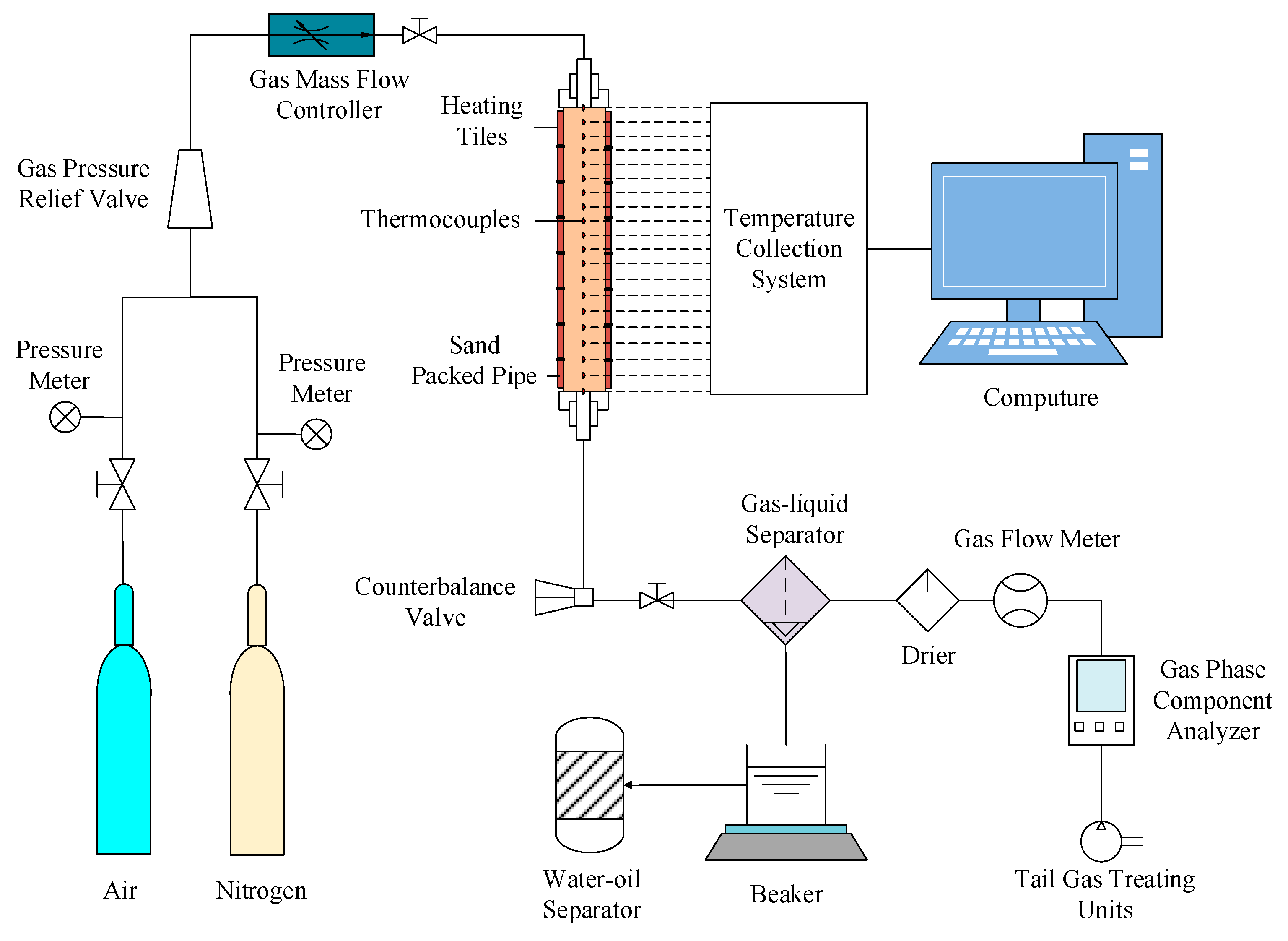
2.1. Experimental Apparatus and Procedures

The experimental device was enhanced based on the high-temperature and high-pressure thermal compensation one-dimensional displacement experimental platform. It has a maximum pressure of 40 MPa and a maximum temperature of 800 °C. The upgraded device takes into account both high-temperature and high-pressure performance and can realize one-dimensional linear thermal drive processes under dynamic near-adiabatic conditions. The upgraded device has a tube length of 1 m, an inner diameter of 5.28 cm, 31 temperature measuring points, and 16 heating tiles.
The experimental device achieves temperature stability by multi-position compensation temperature control and multi-point temperature measurement, and the temperature accuracy is ±1 °C. The full model confining pressure cabin and the high-precision back pressure control system can ensure that the pressure is constant during the experiments. The pressure accuracy is 0.25% FS. The experimental device can be applied to a variety of scenarios, suitable for core displacement and sand-packed tube displacement, enabling precise injection of gases and chemical reagents. The experimental platform uses computer technology to realize full-process automation, full-cycle digital recording and high-precision data acquisition. The experimental apparatus is shown in Figure 1.
(1)
Quartz sand with different mesh ratios was filled into the sand-packed tube and compacted. The output end of the model was connected to the vacuum pump to ensure that the vacuum degree reached below 10 Pa.
(2)
The injection end of the model was connected to the advection pump, and the formation water was injected at a constant speed until the output end continuously produced water, and the saturation with water was completed. At the same time, the porosity of the sand-packed tube was calculated based on the volumes of injected and produced water.
(3)
Initial imbibition of oil into the sands was performed. Subsequently, the advection pump was continuously utilized to displace the already saturated formation water with the crude oil until no more water was produced, and the saturation with oil was completed. The initial oil saturation was calculated based on the volume of injected and produced crude oil and produced water.
(4)
For the experiments of air injection after water injection, it was necessary to inject water according to the designed oil saturation and record the produced water and oil during the water injection process.
(5)
The backpressure data were set, and the ignition equipment was turned on. Once the ignition equipment reached 450 °C, the gas mass flow controller was opened to inject air at the ventilation intensity designed for the experiment. During the experiment, the temperature changes in the model were recorded, the volumes of produced gas and fluids were measured, the production gas components were analyzed, and the experimental results were recorded.
(6)
After the experiment, the experimental equipment was cleaned, and the experiments were repeated by changing the backpressure data.

2.2. Experimental Materials

(1)
Quartz sand: Three types of quartz sand with particle sizes of 100 mesh, 200 mesh, and greater than 1000 mesh were utilized.
(2)
Oil sample: Light oil samples of the Hudson reservoir in Tarim oilfield were used. Crude oil samples were first filtered with a stainless steel mesh with a pore size of 200 mesh at a temperature below 80 °C. After filtration, dehydration was performed at a temperature below 130 °C. Oil samples with water cut below 0.3% were considered qualified.
(3)
Gas sample: The gas used in the experiment included air and nitrogen. The impurity mass content was not higher than 0.5% air, and purity was not less than 99.9% nitrogen.
(4)
Water sample: The water used in the experiment had the same salinity as the formation water (252,000 mg/L), and it was CaCl2-type water.

2.3. Experimental Scheme

The main purpose of this experiment was to explore the mechanism and characteristics of thermal-assisted miscible displacement under different pressure conditions and water injection conditions. All experiments were initiated at an ignition temperature of 450 °C, and the ventilation intensity was 40 m3/(m2 h). The porosity of the one-dimensional oxidation tube model was 43%, and the permeability was 1500 mD. The first three groups were different pressure experiments from low pressure (5 MPa) to high pressure (30 MPa). The fourth group was the 30 MPa air injection experiment after water injection. The recovery degree after water injection was 59.8%. The design scheme is shown in Table 1.

3. Air Injection Displacement Experiment of Different Pressure

Under the same conditions of model physical parameters, ignition temperature, and ventilation intensity, air injection experiments with different pressures of 5 MPa, 15 MPa, and 30 MPa were carried out. The experiments were initiated at an ignition temperature of 450 °C, the ventilation intensity was 40 m3/(m2 h), and the initial temperature of the experiment was 105 °C.

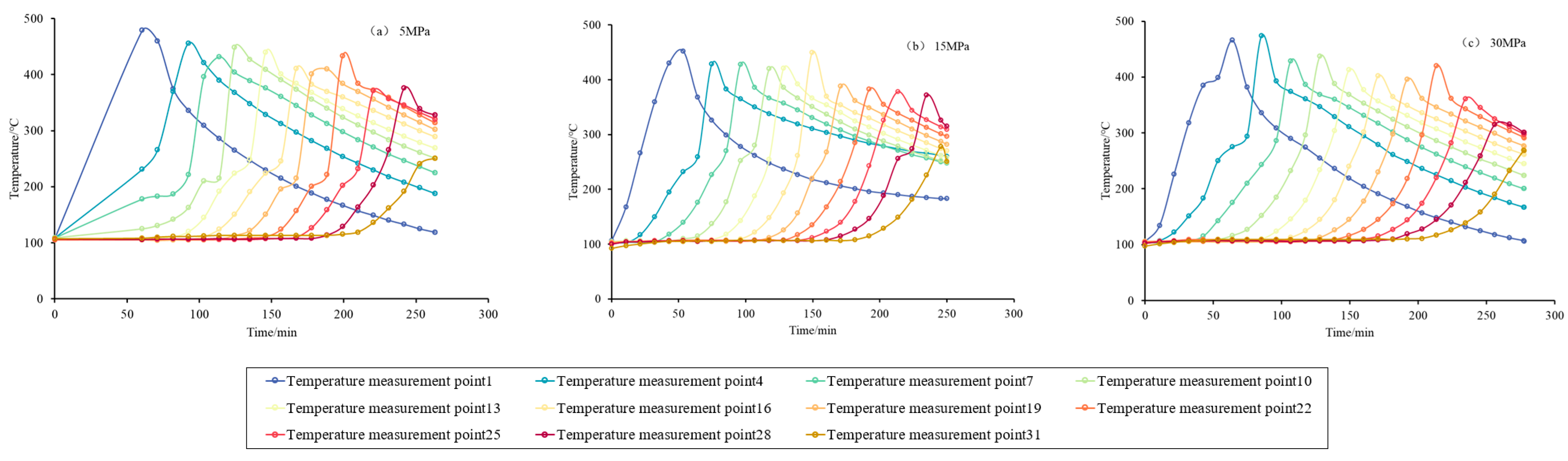
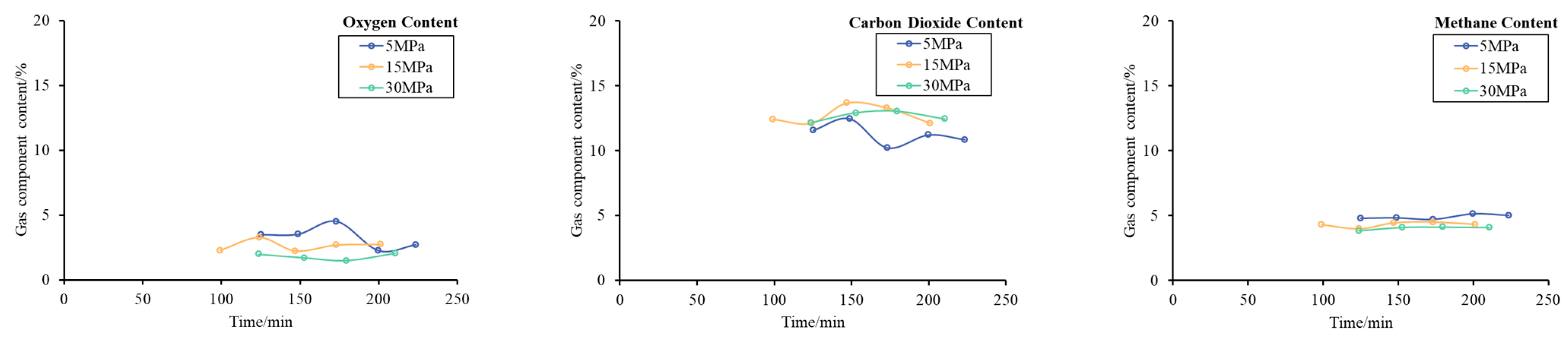
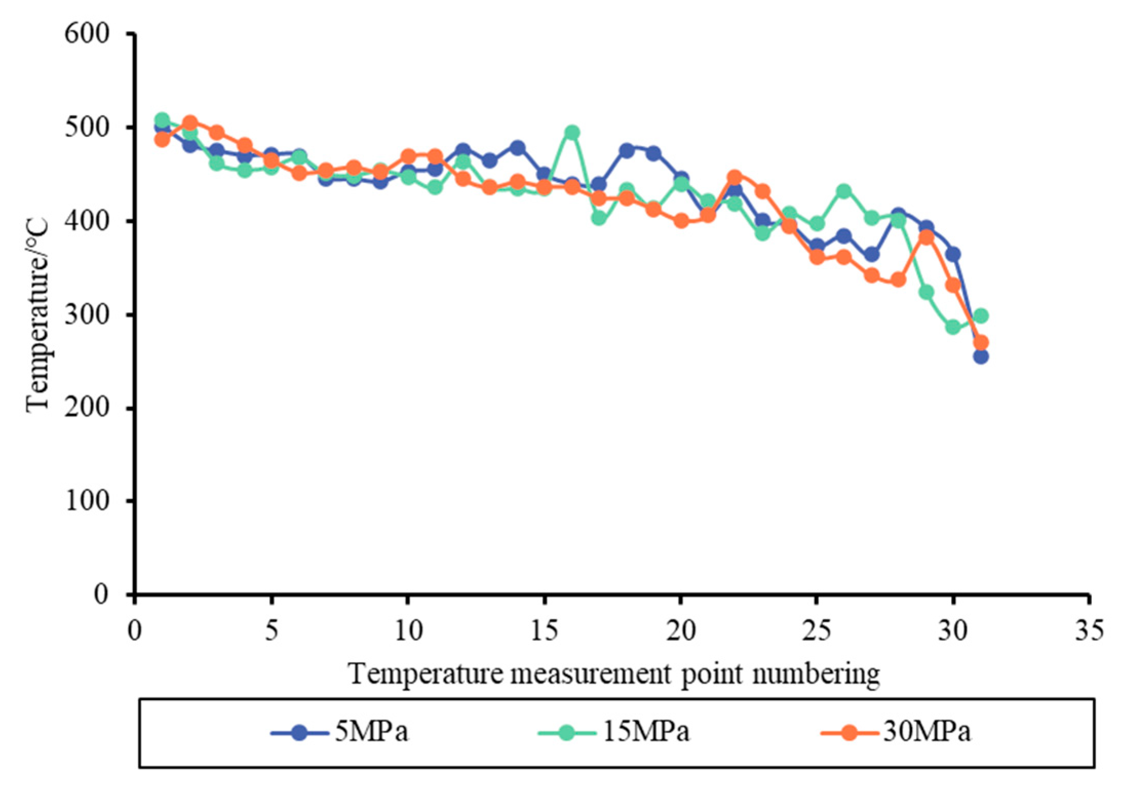
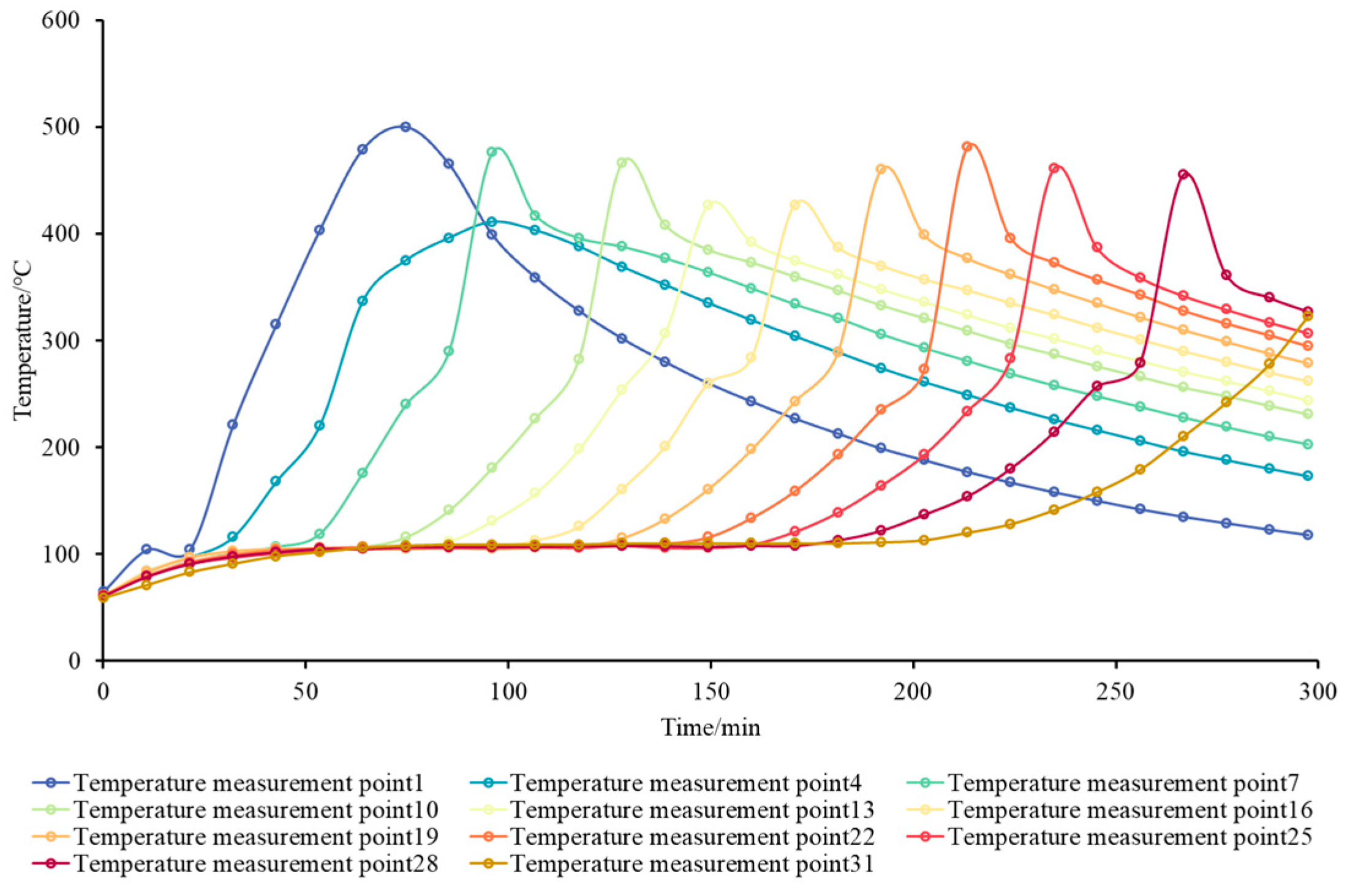
3.1. Oxidation Displacement Characteristics of Different Pressure Experiments

Figure 2 shows the temperature variation curves of different pressure experiments under the same ventilation conditions. It can be seen from the figure that 5 MPa, 15 MPa, and 30 MPa pressure experiments can form a stable thermal oxidation front, and the temperature of the oxidation front is greater than 350 °C, achieving medium–high-temperature oxidation. In the whole process of air injection displacement development, the oxidation front can be steadily pushed forward, and the propulsion characteristics are similar to those of heavy oil in situ combustion.
Table 2 is the gas composition table of different pressure experiments, and Figure 3 is the gas composition chart of different pressure experiments. This study mainly compares the content of oxygen, carbon dioxide, and methane in the production gas. The average oxygen content in the stable stage of 5 MPa, 15 MPa, and 30 MPa experiments is below 3%, the carbon dioxide content is more than 11%, and the methane content is maintained above 4%, indicating that the oxygen consumption of light oil air injection is sufficient, and the safety production can be realized. The effect of oxidation and modification at medium–high temperatures is obvious. The oxidation state of 5 MPa, 15 MPa, and 30 MPa is relatively stable in the process of air injection.
Figure 4 shows the comparison curve of the oxidation front temperature of different pressure experiments. The average oxidation front temperature of 5 MPa, 15 MPa, and 30 MPa experiments is 433.22 °C, 426.45 °C, and 423.06 °C, respectively. It can be seen that the average oxidation front temperature of the 5 MPa experiment is the highest, the average oxidation front temperature of the 15 MPa experiment is the second, and the average oxidation front temperature of the 30 MPa experiment is the lowest. In contrast, under the same ventilation intensity, the temperature of the oxidation front decreases with the increase in the pressure of the air injection experiments. From the previous research results, for heavy oil, under the same ventilation intensity conditions, the pressure of the air injection experiment rises, and the temperature of the oxidation front rises [18,19]. The variation law of the oxidation front temperature of the light oil with pressure is completely different from that of the heavy oil.
The content of resin, asphaltene, and other heavy components in heavy oil is high. The fuel in the process of high-temperature in situ combustion is mainly coke formed by cracking and condensation [20]. Therefore, heavy oil is less affected by the distillation phase transition. The higher the pressure, the faster the oxidation reaction rate, the more the cracking and condensation synthesis of coke, and the more the oxidation reaction fuel produced. Therefore, the fuel consumed in the oxidation reaction increases, and the temperature of the oxidation front increases. In contrast, the content of light components in light oil is high, and the oxidation reaction fuel is mainly the residual heavy components after displacement [6]. The light oil is significantly affected by the distillation phase transition. The higher the pressure, the more obvious the effect of dissolution and distillation phase transition miscibility. The higher the oil displacement efficiency, the less the remaining oil after displacement at the oxidation front. Concurrently, the air consumption and fuel consumption of the oxidation reaction decreased, and the temperature of the oxidation front decreased accordingly. The air consumption in the heavy oil in situ combustion standard is defined as the volume of air consumed by the combustion zone sweeping through the unit volume of oil sands under standard conditions [21]. It is calculated as the ratio of the injected air volume to the volume swept through the oil sand in the stable stage of the heavy oil air injection experiment, and the gas storage in the pore volume is not considered in the calculation process. Using this standard, the air consumption of the 5 MPa experiment is 118.46 m3/m3, the air consumption of the 15 MPa experiment is 129.49 m3/m3, and the air consumption of the 30 MPa experiment is 144.78 m3/m3. The calculation results show that under the same ventilation intensity, the air consumption of the 30 MPa experiment is the largest, and the corresponding oxidation front temperature should also be the highest. However, this result is obviously inconsistent with the experimental results that the front temperature is the highest under the condition of 5 MPa and the lowest under the condition of 30 MPa.
The main reason is that the experimental pressure of heavy oil air injection is generally not more than 8 MPa [18]. The degree of injection gas compression during the experiment is low, and the gas storage is small. Therefore, the gas storage in the pores can be ignored. The calculated oxidation parameters can relatively accurately reflect the oxidation reaction characteristics. However, the formation pressure of light oil reservoir is high, and the degree of injection gas compression is high. In the process of the air injection experiment of light oil, the gas storage in pores is large. Therefore, the key parameters of oxidation in high-pressure light oil cannot be solved by copying the calculation method of heavy oil, and the method of calculating air consumption by heavy oil in situ combustion standard is not suitable for the calculation of oxidation parameters of light oil.
Considering the condition of gas storage, the air consumption of air injection in light oil was calculated, and the air consumption of light oil is defined as the air volume consumed by the oxidation front sweeping through a unit volume of oil sand minus the air volume stored in the pores. Table 3 shows the oxidation reaction parameters of different pressure experiments considering gas storage. It can be seen from the table that the air consumptions of 5 MPa, 15 MPa, and 30 MPa are 106.69, 92.50, and 76.81 m3/m3, respectively. The air consumption and fuel consumption of 5 MPa are the highest, and the air consumption and fuel consumption of 30 MPa are the lowest. This is the same as the law that the temperature of the oxidation front decreases with the increase in pressure. Therefore, the calculation of oxidation parameters of high-pressure air injection needs to consider the influence of gas storage, which can more accurately reflect the oxidation state.

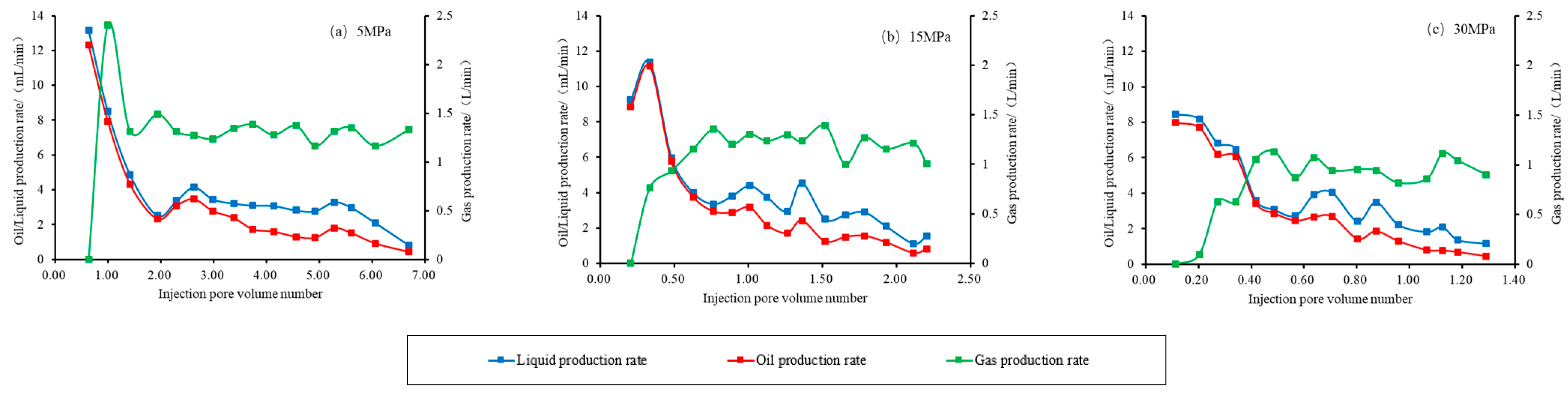
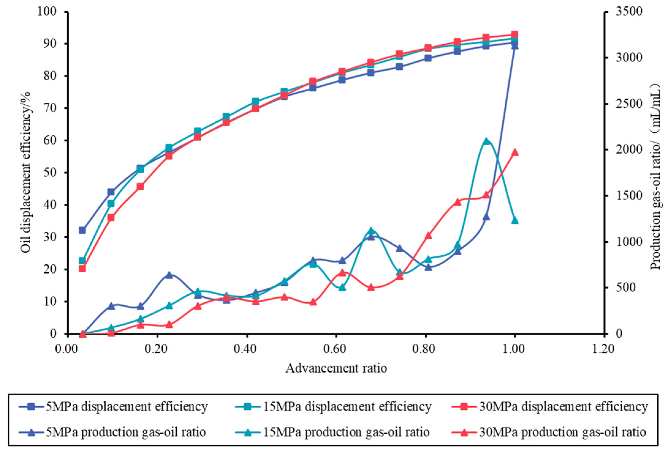
3.2. Production Dynamic Characteristics of Different Pressure Experiments

By analyzing the key production parameters such as liquid production and gas production, the displacement characteristics and development stability can be clarified.
Figure 5 shows the production dynamic curve of different pressure experiments. The characteristics of different pressure experiment production stages are basically the same. The initial production is higher, and then the production gradually decreases to a stable level. The oil production in the stable stage is about 2 mL/min. After a period of stable production, the production decreases.
Table 4 shows the cumulative production dynamic parameters of different pressure experiments. The cumulative gas production–injection ratios of 5 MPa, 15 MPa, and 30 MPa experiments are 0.91, 0.76, and 0.56, respectively. It can be seen from the production gas–oil ratio curve in Figure 6 that the average GOR in the stable production stage of 5 MPa, 15 MPa, and 30 MPa experiments is 675.49 mL/mL, 605.78 mL/mL, and 520.02 mL/mL. Compared with the 5 MPa, 15 MPa, and 30 MPa experimental gas production–injection ratio and GOR, the gas production–injection ratio is small under high-pressure conditions, the gas storage volume is relatively large, the gas production time is late, the GOR is low, the output gas volume is less, the gas channeling does not easily occur, and the stability of the air injection displacement process is enhanced under high pressure.
As shown in Figure 5, during the displacement process at 5 MPa, a total of 6.7 PV of air was injected, resulting in a final oil displacement efficiency of 90.5%. At 15 MPa, 2.2 PV of air was injected, resulting in a final oil displacement efficiency of 91.80%. Under 30 MPa conditions, only 1.3 PV of air was injected, and the final oil displacement efficiency reached 92.93%. By comparison, under 30 MPa, the injected PV number approached 1, with a displacement rate exceeding 90%, indicating the miscible state during the air injection displacement, resulting in a more stable displacement process.
In general, with the increase in pressure, the gas production–injection ratio decreases, the gas production time is delayed, the GOR becomes lower, the injected PV number decreases, and the oil displacement efficiency increases.

4. Air Injection Displacement Experiment of Light Oil Reservoir After Water Injection

In this study, experiments were carried out by simulating air injection after water injection in actual reservoirs. For this experiment, the pressure is 30 MPa, the ventilation intensity is 40 m3/(m2 h), and the experimental temperature is maintained at 105 °C. The initial oil saturation of the model is 84.53%. When the water injection reaches a water cut of 97%, the recovery degree of water flooding is 59.8%, and the average oil saturation is 34% at this point.

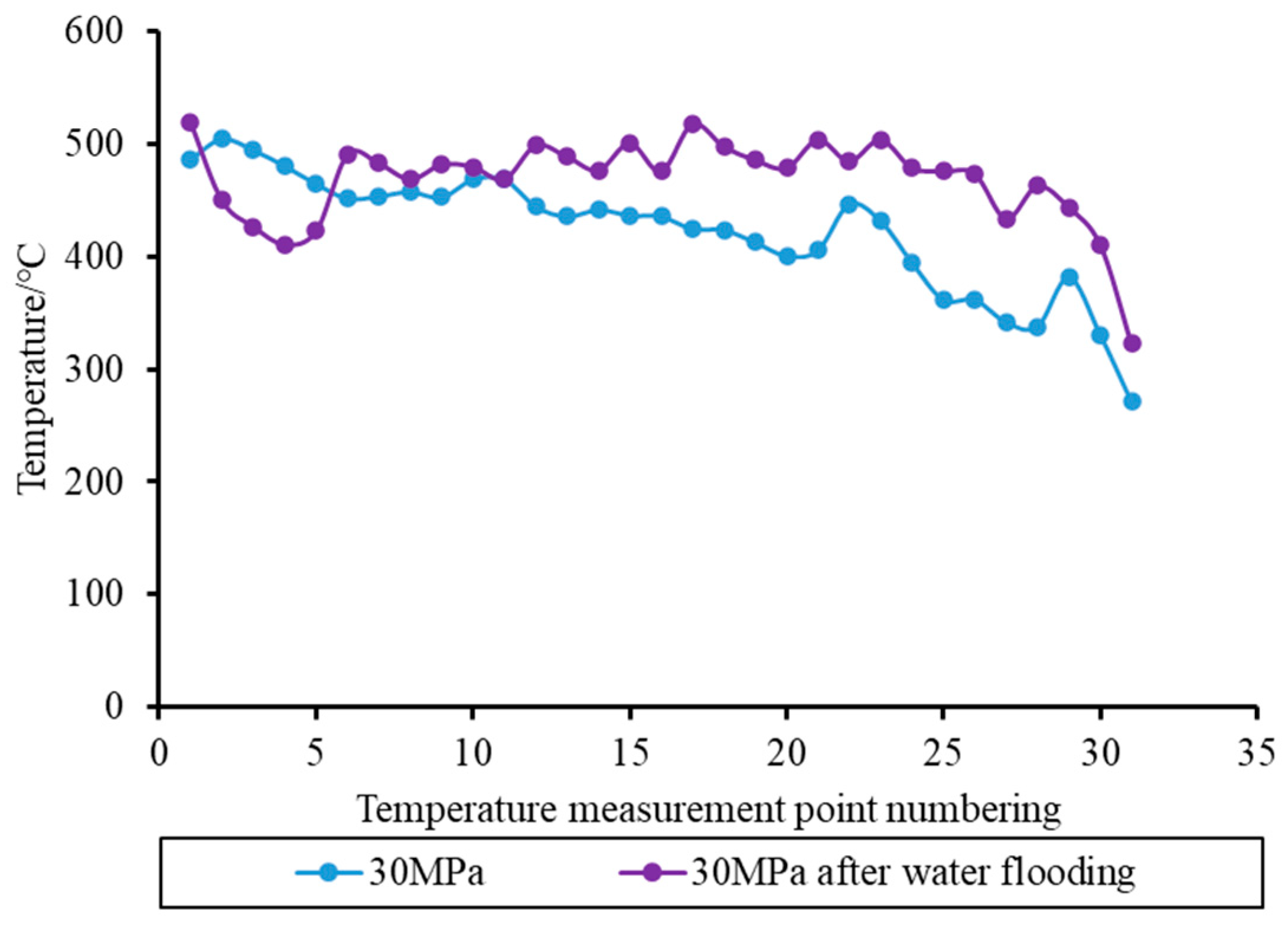
4.1. Oxidation Displacement Characteristics of Experiment After Water Injection

Figure 7 shows the temperature variation curve of the air injection experiment after water flooding. As shown in Figure 7, the temperature of the oxidation front of air injection after water injection is above 350 °C, the oxidation front can be steadily advanced, and the oxidation state of air injection after water injection is stable.
Table 5 is the gas composition table of air injection and air injection after water injection experiments. In terms of the content of the produced gas, the average oxygen content of the produced gas in the air injection experiment after water injection is 2.03%, the average carbon dioxide is 12.49%, and the methane content is 4.71%. This shows that the oxygen consumption of the oxidation reaction is sufficient, and a stable high-temperature oxidation reaction occurs. The high-temperature oxidation modification effect is obvious.
Figure 8 shows the temperature comparison curve of the oxidation front in the experiment of direct air injection and air injection after water injection. The average oxidation front temperature of the direct air injection experiment is 423.06 °C, and the advancing speed of the oxidation front is 268.75 mm/h. The average oxidation front temperature of the air injection experiment after water flooding is 468.51 °C, and the advancing speed of the oxidation front is 239.60 mm/h. As shown in Table 6, the air consumption of the 30 Mpa air injection experiment is 76.81 m3/m3, and the air consumption of the air injection experiment after water injection is 91.34 m3/m3. Compared with the air injection in the original reservoir, the air consumption and fuel consumption of the air injection after the water injection experiment increase, the temperature of the experimental oxidation front becomes higher, and the oxidation front is more stable. The results of air injection in heavy oil reservoirs show that the oil saturation of heavy oil reservoirs decreases after steam injection, and the in situ combustion after steam injection has the characteristics of ‘limited wet burning’. Compared with the original reservoir, the temperature of the oxidation front of the heavy oil reservoir after steam injection becomes lower [22,23]. The variation law of oxidation front temperature in a high-pressure light oil reservoir with low oil saturation after water flooding exhibits a distinct pattern compared to that in a low-pressure heavy oil reservoir.
After the development of water injection, the oil saturation of the formation decreases, but the air consumption and fuel consumption of the oxidation reaction increase, and the temperature of the oxidation front increases. It is speculated that there are two main reasons. One is that oleic acid substances produced by the oxidation reaction promote the formation of water-in-oil emulsions in the reservoir [24,25,26]. The viscosity of water-in-oil emulsions increases greatly, and the oil displacement efficiency becomes low, so there is more remaining oil, and the air consumption and fuel consumption during air injection are larger. The second reason is that the critical temperature of water is 375.15 °C, and the critical pressure is 22.12 MPa. Different from the steam flooding process in low-pressure heavy oil reservoirs, the temperature and pressure around the oxidation front are greater than the critical value of water. Water is in a supercritical state, and the effect of steam flooding is weakened. In addition, high-pressure supercritical water has a catalytic effect on chemical reactions and can accelerate oxidation reactions [27]. From the current experimental results of high-pressure light oil air injection and the characteristics of oxidative displacement, the characteristics and mechanism of deep high-pressure light oil air injection displacement are very complex, and the deep mechanism still needs to be further demonstrated by microscopic displacement experiments and visualization experiments.

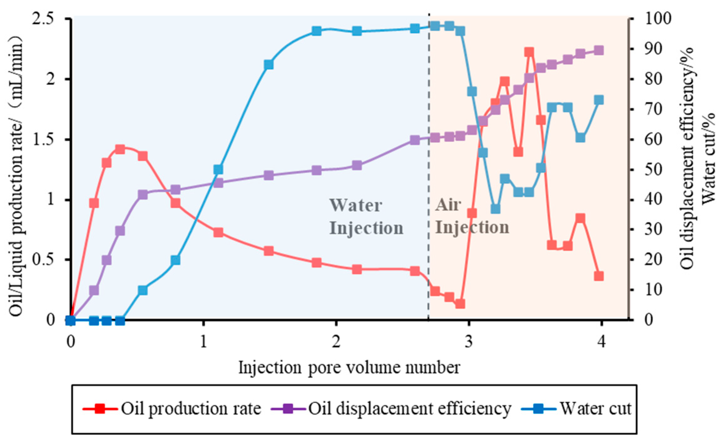
4.2. Production Dynamic Characteristics of Experiment After Water Injection

As can be seen from Figure 9, 2.5 L of water (2.59 PV underground) was injected during the water injection stage. At the end of the water injection stage, the oil displacement efficiency was 59.8%, and the water cut was 97%, entering the high-water-cut stage. During the 0–0.5 PV stage of water injection, no water was seen at the production end, and the oil production rate continued to rise to 1.42 mL/min; when water was seen at the production end, the oil production rate continued to decline, and the oil production rate at the end of the water injection stage was 0.41 mL/min.
After water flooding, the oil saturation is reduced to 34%. In the air injection development stage, a total of 350.42 L air (1.39 PV underground) was injected. In the early stage of air injection, the water cut remained at a high level, which was in the drainage stage. In the stable production stage of air injection, the water cut decreased to 42.52%, and the oil production rate increased to 2.22 mL/min, which was higher than the maximum oil production rate in the water injection stage and 5.4 times of the oil production rate at the end of water injection. According to the oil displacement efficiency and production gas–oil ratio curve of air injection and air injection after water injection experiments as shown in Figure 10, air injection can overcome the problem of oil saturation reduction after water injection, and the GOR is stable. The oil displacement efficiency of the air injection development stage is increased by 30 percentage points, and the final oil displacement efficiency is 89.54%. Air injection development after water injection can significantly improve the oil production rate, reduce the water cut, and greatly improve oil recovery.

5. Conclusions

(1)
In this paper, a calculation method for air injection air consumption considering gas storage in light oil reservoirs is proposed. The air consumption of light oil is defined as the air volume consumed by the oxidation front minus the volume of stored gas in the pores sweeping through the unit volume of oil sand minus the volume of stored gas in the pores, which can more accurately reflect the oxidation state.
(2)
Air injection of 5 MPa, 15 MPa, and 30 MPa experiments can form a stable oxidation state and displacement state. The temperature of the oxidation front is greater than 350 °C, and the oil displacement efficiency is greater than 90%. With the increase in the pressure of the light oil air injection experiments, the oil displacement efficiency improved, resulting in less remaining oil at the oxidation front. Concurrently, the air consumption and fuel consumption of the oxidation reaction decreased, and the temperature of the oxidation front decreased accordingly.
(3)
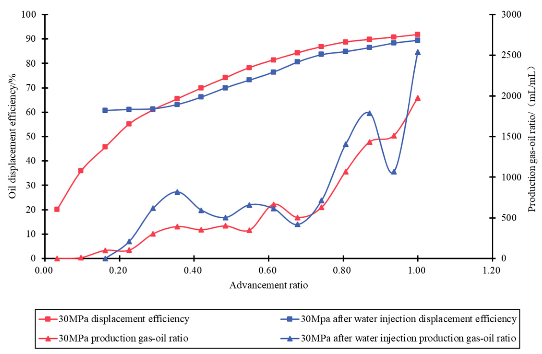
When the experimental pressure is higher, the gas production–injection ratio decreases. The gas production time is late, and the production gas–oil ratio is low, minimizing the risk of gas channeling. Under 30 MPa pressure conditions, the air injection displacement process demonstrates excellent stability.
(4)
Compared with the air injection in the original reservoir, the air consumption and fuel consumption of the air injection after water injection experiments increase, the temperature of the experimental oxidation front becomes higher, and the oxidation front is more stable. The main reason may be the formation of water-in-oil emulsion and supercritical water during the displacement and the promotion effect on the oxidation reaction.
(5)
Overall, after water injection, air injection in high recovery reservoirs can form a stable oxidation state, and the temperature of the oxidation front is greater than 350 °C. The thermal oxidation front is uniformly advanced, which can significantly increase the oil production rate, reduce the water cut, and greatly improve the oil production rate. The oil displacement efficiency in the air injection stage is increased by 30 percentage points.
(6)
Air injection technology is expected to become a strategic development technology with potential for deep reservoirs with high permeability, high temperature, high salinity, and high water saturation.

Author Contributions

Conceptualization, Z.Z. and C.X.; methodology, B.W. and P.L.; software, F.Z.; validation, F.Z. and C.X.; formal analysis, Z.Q.; investigation, T.L.; resources, Z.Q. and B.W.; data curation, T.L.; writing—original draft preparation, Z.Z.; writing—review and editing, C.X.; visualization, D.H. and X.Z.; supervision, F.Z. and C.X. All authors have read and agreed to the published version of the manuscript.

Funding

The authors would like to acknowledge the financial support of the China National Petroleum Corporation Technology Project (2023ZG18).

Institutional Review Board Statement

Ethical review and approval were waived for this study due to the absence of human or animal involvement.

Informed Consent Statement

Written informed consent has been obtained from the patient(s) to publish this paper.

Data Availability Statement

The data that support the findings of this study are available from the authors.

Conflicts of Interest

Authors Zeqi Zhao, Changfeng Xi, Bojun Wang, Peng Liu, Fang Zhao, Zongyao Qi, Tong Liu, Daode Hua and Xiaokun Zhang were employed by the company PetroChina. The authors declare that the research was conducted in the absence of any commercial or financial relationships that could be construed as a potential conflict of interest.

References

  1. Huo, J.; Zhao, R.B.; Sun, X.G.; Yang, F.X. Progress of ISC technology and perspective on the future work of its theoretical research. Xinjiang Oil Gas 2021, 17, 30–36. [Google Scholar] [CrossRef]
  2. Denney, D. 30 years of successful high-pressure air injection: Performance evaluation of Buffalo field, south Dakota. J. Pet. Technol. 2011, 63, 50–53. [Google Scholar] [CrossRef]
  3. Cheih, C. State-of-the-Art Review of Fireflood Field Projects (includes associated papers 10901 and 10918). J. Pet. Technol. 1982, 34, 19–36. [Google Scholar] [CrossRef]
  4. Liao, G.; Wang, Z. High-efficiency, Low-cost and Green Air Injection Development Technology of New Generation. Pet. Sci. Technol. Forum 2020, 39, 59–66. [Google Scholar] [CrossRef]
  5. Barzin, Y.; Moore, R.G.; Mehta, S.A.; Ursenbach, M.G.; Tabasinejad, F. Impact of Distillation on the Combustion Kinetics of High Pressure Air Injection (HPAI); SPE Improved Oil Recovery Symposium: Tulsa, OK, USA, 2010. [Google Scholar] [CrossRef]
  6. Xi, C.; Wang, B.; Zhao, F.; Liu, T.; Qi, Z.; Zhang, X.; Tang, J.; Jiang, Y.; Guan, W.; Wang, H.; et al. Oxidization characteristics and thermal miscible flooding of high pressure air injection in light oil reservoirs. Pet. Explor. Dev. 2022, 49, 760–769. [Google Scholar] [CrossRef]
  7. Xi, C.; Wang, B.; Zhao, F.; Hua, D.; Qi, Z.; Liu, T.; Zhao, Z.; Tang, J.; Zhou, Y.; Wang, H. Miscibility of light oil and flue gas under thermal action. Pet. Explor. Dev. 2024, 51, 147–153. [Google Scholar] [CrossRef]
  8. Jia, H.; Yuan, C.-D.; Zhang, Y.-C.; Peng, H.; Zhong, D.; Zhao, J.-Z. Recent Progress of High Pressure Air Injection Process (HPAI) in Light Oil Reservoir: Laboratory Investigation and Field Application. In Proceedings of the SPE Heavy Oil Conference Canada, Calgary, AB, Canada, 12–14 June 2012. [Google Scholar] [CrossRef]
  9. Li, Y.-B.; Chen, Y.-F.; Pu, W.-F.; Peng, H.; Zhong, D.; Hu, X.-T.; Sun, B.-S. The influence factors analysis of the light crude oil oxidation reaction process. Pet. Sci. Technol. 2016, 34, 609–614. [Google Scholar] [CrossRef]
  10. Chen, Z.; Wang, L.; Duan, Q.; Zhang, L.; Ren, S. High-pressure air injection for improved oil recovery: Low-temperature oxidation models and thermal effect. Energy Fuels 2013, 27, 780–786. [Google Scholar] [CrossRef]
  11. Zhao, J.-Z.; Jia, H.; Pu, W.-F.; Wang, L.-L.; Peng, H. Sensitivity Studies on the Oxidation Behavior of Crude Oil in Porous Media. Energy Fuels 2012, 26, 6815–6823. [Google Scholar] [CrossRef]
  12. Li, Y.-B.; Zhao, J.-Z.; Pu, W.-F.; Peng, H.; Zhong, D.; Hu, Z.-W. A method based on the Harcourt and Esson equation to estimate the catalytic effect of metallic additives on light crude. J. Alloys Compd. 2014, 585, 7–13. [Google Scholar] [CrossRef]
  13. Ren, S.R.; Greaves, M.; Rathbone, R.R. Air injection LTO process: An lOR technique for light-oil reservoirs. SPE J. 2002, 7, 90–99. [Google Scholar] [CrossRef]
  14. Moore, R.G.; Mehta, S.A.; Ursenbach, M.G. A Guide to High Pressure Air Injection (HPAI) Based Oil Recovery. In Proceedings of the SPE/DOE Improved Oil Recovery Symposium, Tulsa, OK, USA, 13–17 April 2002. [Google Scholar] [CrossRef]
  15. Clara, C.; Durandeau, M.; Quenault, G.; Nguyen, T.-H. Laboratory Studies for Light-Oil Air Injection Projects: Potential Application in Handil Field. SPE Reserv. Eval. Eng. 2000, 3, 239–248. [Google Scholar] [CrossRef]
  16. Moore, R.G.; Mehta, S.A.; Ursenbach, M.G.; Gutierrez, D. Potential for In Situ Combustion in Depleted Conventional Oil Reservoirs. In Proceedings of the SPE Improved Oil Recovery Symposium, Tulsa, OK, USA, 14–18 April 2012. [Google Scholar] [CrossRef]
  17. Yuan, S.; Han, H.; Wang, H.; Luo, J.; Wang, Q.; Lei, Z.; Xi, C.; Li, J. Research progress and potential of new enhanced oil recovery methods in oilfield development. Pet. Explor. Dev. 2024, 51, 841–854. [Google Scholar] [CrossRef]
  18. Zhao, J.; Zhang, N.; Jiang, H.; Jiao, P. Experimental study on oxidation characteristics of heavy oil reservoirs by high-pressure in-situ combustion. Pet. Geol. Recovery Effic. 2023, 30, 145–151. [Google Scholar] [CrossRef]
  19. Li, Y.-B.; Chen, Y.-F.; Pu, W.-F.; Jin, F.-Y.; Yuan, C.-D.; Li, D.; Zhao, J.-Y.; Zhou, W. The Kinetic Analysis of Oxidized Oil During the High Pressure Air Injection by Thermal Kinetic Analysis. Liq. Fuels Technol. 2015, 33, 319–326. [Google Scholar] [CrossRef]
  20. Sun, X.; Yang, F.; Li, H.; Zhan, H.; Gao, C.; Yuan, S. Component transformation path in the process of heavy oil fire flooding based on core analysis. Spec. Oil Gas Reserv. 2024, 31, 85–90. [Google Scholar] [CrossRef]
  21. SY/T 6898-2012; Experimental Testing Method of In-Situ Combustion Parameters. National Energy Administration: Beijing, China, 2012.
  22. Xi, C.; Guan, W.; Jiang, Y.; Liang, J.; Zhou, Y.; Wu, J.; Wang, X.; Cheng, H.; Huang, J.; Wang, B. Numerical simulation of fire flooding for heavy oil reservoirs after steam injection: A case study on Block Hl of Xiniiang Oilfield, NW China. Pet. Explor. Dev. 2013, 40, 715–721. [Google Scholar] [CrossRef]
  23. Wang, W. Influence of different oil saturation on fire flooding. Pet. Reserv. Eval. Dev. 2021, 11, 465–468. [Google Scholar] [CrossRef]
  24. He, M. Study on influencing factors of physical properties of water-in-oil emulsion. China Sci. Technol. Inf. 2016, 2, 102–103. [Google Scholar] [CrossRef]
  25. Chen, Q.; Liu, Y.; Hou, J.; Li, X.; Wei, B.; Du, Q. Phase Transition Characteristics of Heavy Oil-Viscosity Reducer-Water Emulsion Systems. J. Mol. Liq. 2023, 379, 121638. [Google Scholar] [CrossRef]
  26. Shi, L.; Tang, W.; Zhou, Y.; Wang, B. Study on Water Flooding with Self⁃Emulsification in Heavy Oil Reservoirs. Xinjiang Pet. Geol. 2024, 45, 228–234. [Google Scholar] [CrossRef]
  27. Liang, J.; Li, F. Supercritical water-a new chemical medium. Chem. Educ. 2001, 22, 7–9. [Google Scholar]
Figure 1. High-temperature and high-pressure tracking thermal compensation one-dimensional displacement experimental apparatus diagram.
Applsci 15 03301 g001
Figure 2. Temperature variation chart of different pressure experiments.
Applsci 15 03301 g002
Figure 3. Gas composition chart of different pressure experiments.
Applsci 15 03301 g003
Figure 4. Oxidation front temperature comparison chart of different pressure experiments.
Applsci 15 03301 g004
Figure 5. Production dynamic chart of different pressure experiments.
Applsci 15 03301 g005
Figure 6. Oil displacement efficiency and production gas–oil ratio chart of different pressure experiments.
Applsci 15 03301 g006
Figure 7. Temperature variation chart of air injection experiment after water injection.
Applsci 15 03301 g007
Figure 8. Oxidation front temperature comparison chart of air injection and air injection after water injection experiments.
Applsci 15 03301 g008
Figure 9. All-lifecycle production dynamic chart of air injection experiment after water injection.
Applsci 15 03301 g009
Figure 10. Oil displacement efficiency and production gas–oil ratio chart of air injection and air injection after water injection experiments.
Applsci 15 03301 g010
Table 1. Tarim oilfield Hudson light oil air injection thermal-assisted miscible experimental design scheme.
NumberingExperiment TypeExperimental Pressure, MPaExperimental
Temperature, °C
Experimental ConditionVentilation Intensity, m3/(m2 h)
1Hudson light oil air injection5105/40
2Hudson light oil air injection15105/40
3Hudson light oil air injection30105/40
4Hudson light oil air injection30105Water flooding40
Table 2. Gas composition table of different pressure experiments.
NumberingExperimental Pressure, MPaAverage Oxygen Content (%)Average Carbon Dioxide Content (%)Average Methane Content (%)
153.2911.264.91
2152.6412.724.31
3301.8112.644.05
Table 3. Oxidation reaction parameters of different pressure experiments considering gas storage.
NumberingExperimental Pressure, MPaAir Injection Volume, LGas Production, LGas Storage Volume, LAir Consumption, m3/m3Fuel Consumption, kg/m3Air Consumption (Considering Gas Storage), m3/m3
15302.7827725.78118.469.93106.69
215313.5823974.58129.499.8192.50
330333.21188145.21144.789.3176.81
Table 4. Cumulative production dynamic parameters of different pressure experiments.
NumberingExperimental Pressure, MPaOil Saturation, %Saturated Oil Volume, mLTotal Liquid Production, mLTotal Oil Production, mLTotal Gas Production, LGas Production–Injection Ratio
1585.45805.00848.61728.542770.91
21584.65818.43955.09760.612390.76
33084.59830.00945.75761.941880.56
Table 5. Gas composition table of air injection and air injection after water injection experiments.
NumberingExperimental Pressure, MPaAverage Oxygen Content (%)Average Carbon Dioxide Content (%)Average Methane Content (%)
3301.8112.644.05
4302.0312.494.71
Table 6. Oxidation reaction parameters of air injection and air injection after water injection experiments.
NumberingExperimental pressure, MPaExperimental ConditionAir Injection Volume, LGas Production, LGas Storage Volume, LFuel Consumption, kg/m3Air Consumption (Considering Gas Storage), m3/m3
330/333.21188145.219.3176.81
430Water injection350.42200150.429.7491.34
Disclaimer/Publisher’s Note: The statements, opinions and data contained in all publications are solely those of the individual author(s) and contributor(s) and not of MDPI and/or the editor(s). MDPI and/or the editor(s) disclaim responsibility for any injury to people or property resulting from any ideas, methods, instructions or products referred to in the content.

